Corrosion Behavior of Fe/Zr Composite Coating on ZK60 Mg Alloy by Ion Implantation and Deposition


1
School of Mechanical Engineering, Hebei University of Technology, Tianjin 300130, China
2
Beijing Key Laboratory for Advanced Functional Materials and Thin Film Technology, Beihang University, Beijing 100191, China
3
School of Materials Science and Engineering, Beihang University, Beijing 100191, China
*
Authors to whom correspondence should be addressed.
Coatings 2018, 8(8), 261; https://doi.org/10.3390/coatings8080261
Submission received: 4 July 2018
/
Revised: 19 July 2018
/
Accepted: 25 July 2018
/
Published: 26 July 2018
(This article belongs to the Special Issue Advanced Coatings for Corrosion Protection in Extreme Environments)
Abstract
:The Fe/Zr composite coating was prepared by duplex Fe/Zr ion implantation and deposition to modify the microstructure and corrosion behavior of Mg-5.5 Zn-0.6 Zr (in wt.%, ZK60) alloy. The surface and interface characteristics were investigated using X-ray diffraction (XRD), atomic force microscope (AFM) and scanning electron microscopy (SEM). The results showed that the Fe/Zr composite coating exhibited a bi-layer microstructure of outer Fe-rich layer and inner Zr-rich layer. Multi-phases of α-Fe, ZrO0.35 and Zr6Fe3O were formed on the modified surface. The electrochemical measurements and immersion tests revealed an improvement of corrosion behavior for the surface-modified sample due to the protective effect of Fe/Zr composite coating.
1. Introduction
In recent years, Mg and its alloys have drawn great attention as temporary implants in the orthopedic and cardiovascular fields [1,2]. Compared with traditional biometals (such as stainless steels, titanium alloys, NiTi alloys and Co-Cr alloys), Mg-based alloys possess lower density, higher specific strength and closer Young’s modulus to human bone. The unique biodegradation behavior in physiological environment avoids the necessity of a secondary removal surgery after tissue healing. Furthermore, their degradation products of Mg hydroxides have been evidenced to exhibit positive effect on the osteoblast activity [3,4,5]. However, Mg-based alloys tend to degrade too fast to provide sufficient mechanical strength during tissue healing process and may cause some other problems of local alkalinity, excessive hydrogen aggregation and detached corrosion products, which remains the main obstacle for their clinical applications [6,7].
Various kinds of biocompatible coatings have been prepared via proper surface modification techniques (including sol-gel, surface oxidation, ion beam modification and chemical conversion etc.) to reduce the corrosion rate of Mg-based alloys [8,9,10,11]. Metallic coatings have been proved to exhibit high corrosion resistance, excellent mechanical property, good biocompatibility and favorable electric conductivity, which can simultaneously enhance the corrosion resistance and surface strength without deteriorating the electric conductivity [12,13,14,15,16]. Jin et al. [13] deposited Ta-containing coating on the ZK60 Mg alloy surface by reactive magnetron sputtering and the corrosion resistance and biocompatibility were improved by the modified surface composed of Ta2O5, Ta suboxide and Ta. Ba et al. [14] introduced Sn into Mg-Gd-Zn-Zr alloy surface by ion implantation and found that the Sn-implanted Mg alloy exhibited enhanced corrosion resistance and better mechanical properties due to the formation of SnO2 and MgO on the surface. In addition, composite metallic coatings have been prepared to further modify Mg alloys to obtain desirable corrosion rate. Fu et al. reported that the corrosion rate of AZ91D Mg alloy was obviously reduced by the Al-Mg intermetallic compound coating fabricated by heat treatment in AlCl3-NaCl molten salts, which was attributed to the gradient microstructure of outer Mg2Al3 and inner Mg17Al12 phases formed on the surface [16].
Ion implantation and deposition (II&D), incorporating two successive processes of ion implantation and plasma deposition, is a non-equilibrium method to prepare metallic coatings with compact morphology and high bonding strength [17,18]. In previous studies, different metallic coatings have been prepared by II&D to modify the corrosion behavior of Mg alloys. For example, Al, Zr and Ti II&D were respectively conducted on the AZ91 Mg alloy and an enhanced corrosion resistance was obtained for all three sets of modified samples as a result of the compact metallic oxides and thick intermixed layers formed on the surface [19]. Mg-1Ca alloy was surface modified by Zn II&D using metal vapor vacuum arc plasma source (MEVVA) to improve the cytocompatibility and the corrosion resistance was not obviously decreased by the Zn-modified layer [20].
It is known that Fe is another kind of biodegradable metals and it degrades much slower than Mg [21]. Zr exhibits high hardness and excellent anti-corrosion ability because of the Zr oxide layer automatically formed in air, and it also has good cytocompatibility and anti-bacterial effects [22]. Considering the low corrosion rate of Fe and Zr, an enhanced corrosion resistance of Mg alloy may be obtained by depositing Fe/Zr composite coating with specific microstructure through surface modification of II&D. To our knowledge, few researchers have studied Mg alloy modified by Fe-based coatings due to the immiscibility between Fe and Mg under equilibrium condition [23]. In this work, duplex Fe/Zr II&D was conducted on the ZK60 Mg alloy and the phase constitution, surface topography, interface characteristics and corrosion behavior were investigated.
2. Materials and Methods
2.1. Substrate Pretreatment
The ZK60 Mg alloy with a nominal composition of Mg-5.5 Zn-0.6 Zr (in wt.%) was selected as the substrate. The samples were cut into 10 mm × 10 mm × 2 mm plates by electro-discharge machining. Prior to coating, the samples were firstly ground with SiC emery papers (500, 800, 1200, 1500, 2000 and 3000 grits in sequence) and then mechanically polished using nylon cloth soaked with absolute ethanol and finally rinsed in distilled water by ultrasonic cleaner to obtain smooth and fresh surfaces.
2.2. Coating Preparation
The Fe/Zr composite coating was prepared by duplex Fe/Zr II&D using the metal vapor vacuum arc (MEVVA) plasma source below the pressure of 5 × 10⁻³ Pa. Pure Fe (99.95%) and pure Zr (99.9%), purchased from General Research Institute for Nonferrous Metals of China (Beijing, China), were used as cathodic targets to produce Fe and Zr metallic ion sources, respectively. Two successive processes were carried out on the ZK60 Mg alloy surface: (1) Zr II&D was firstly conducted to form an intermediate layer; (2) Fe II&D was subsequently performed on the Zr-modified surfaces. The processing parameters of Fe/Zr II&D are listed in Table 1. After coating, the samples were ultrasonically cleaned and dried in air. The original and coated samples were nominated as ZK60 and Fe-Zr-ZK60, respectively.
2.3. Microstructure Characterization
The phase constitution was identified by X-ray diffraction (XRD) using Rigaku D/Max 2500 diffractometer (Rigaku, Tokyo, Japan) with Cu Kα radiation at a scanning rate of 2°/min in the 2θ range of 20°–90°. The 3D topography on the surface was characterized by atomic force microscope (AFM, Veeco Instruments, Plainview, NY, USA) in tapping mode with the analysis area of 5 μm × 5 μm and its corresponding average surface roughness (Ra) value was calculated by the Nanoscope Analysis software (Version v150r3). The cross-sectional morphology of coating was observed using scanning electron microscopy (SEM, Apollo-300, CamScan, Cambs, UK) in the backscattered electrons (BSE) mode and its elemental distributions were determined by the energy dispersive X-ray spectrometer (EDX, Oxford Instruments, Abingdon, UK) in the line-scan mode at the electron energy of 20 kV.
2.4. Electrochemical Measurements
The electrochemical measurements were performed at an electrochemical workstation (CHI-660e, CH Instruments, Inc., Shanghai, China) using the three-electrode system with the sample as the working electrode, the saturated calomel electrode (SCE) as the reference electrode and platinum as the counter electrode. All the measurements were done at 37 °C in simulated body fluid (SBF) with a pH value of 7.4. The composition of SBF included 8.035 g/L NaCl, 0.355 g/L NaHCO3, 0.225 g/L KCl, 0.231 g/L K2HPO4·3H2O, 0.311 g/L MgCl2·6H2O, 1.0 M HCl (39 mL), 0.292 g/L CaCl2, 0.072 g/L Na2SO4 and its pH value was buffered to 7.4 with 6.118 g/L Tris and 1.0 M HCl [24]. An exposed area of 1 cm × 1 cm was reserved for electrochemical measurements with the other surfaces being tightly sealed by chloroprene rubber. The electrochemical tests of open circuit potential (OCP) and potentiodynamic polarization were conducted in sequence. The OCP curves were recorded at a scan rate of 1 mV·s−1 for 10 min. The potentiodynamic polarization curves were measured at a scan rate of 1 mV·s−1. The electrochemical parameters of corrosion potential (Ecorr), corrosion current density (icorr) and cathodic slope (βc) were calculated by CHI-660e software through fitting the potential portion commenced 60 mV from Ecorr in the cathodic branch [14,25,26]. At least three samples for each group were taken for average. The corrosion morphology after potentiodynamic polarization was observed by SEM.
2.5. Immersion Tests
The immersion tests were conducted in SBF at 37 °C according to the ASTM-G31-72 standard [27] to investigate the degradation behavior with different immersion times. After each immersion period (1, 3 and 7 days), the samples were taken out, gently rinsed with distilled water and dried in air. The morphology and composition of corrosion products were analyzed using SEM and EDX at the electron energy of 20 kV, respectively. The morphology of corroded surfaces was observed by SEM after completely removing the corrosion products with 200 g·L−1 CrO3 solution. The pH value of SBF at each immersion time was measured by a PHB-4 pH meter (INESA Scientific Instrument, Co., Ltd., Shanghai, China).
3. Results and Discussion
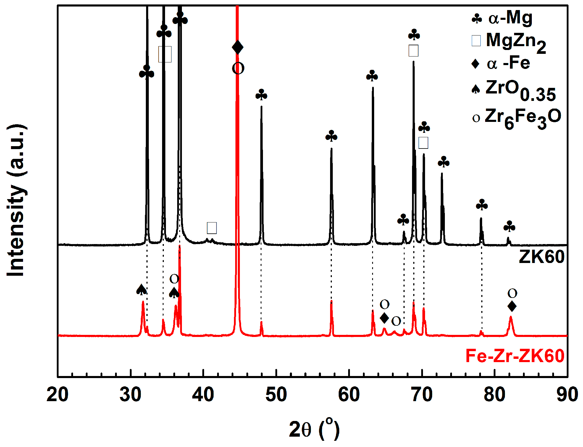
Figure 1 shows the XRD patterns of ZK60 and Fe-Zr-ZK60 samples. The diffraction peaks of ZK60 sample suggest the existence of α-Mg main phase and some MgZn2 second phase [28,29]. For the Fe-Zr-ZK60 sample, there appear some additional peaks and the peak intensity of α-Mg phase is obviously decreased, indicating the formation of new phases. The strong peaks at 44.6°, 64.9° and 82.3° are attributed to the α-Fe phase [30]. The weak peaks are identified as ZrO0.35 (at 31.76°, 36.27°) and Zr6Fe3O (peaks at 36.24°, 44.72°, 64.93°, 66.44°, 82.26°) phases by MDI Jade 6.0, which correspond to the standard PDF #17-0385 and #17-0559, respectively. As a result of the non-ultra-high vacuum condition in the chamber [31], the energetic Zr ions reacted with the residual oxygen to form ZrO0.35 incomplete oxide in the Zr II&D process and the subsequent incident Fe ions bombarded into the Zr-modified surface to produce Zr6Fe3O and α-Fe phases in the Fe II&D process. The Zr6Fe3O phase has a similar crystalline structure (cubic) with α-Fe phase, leading to the overlap of certain diffraction peaks. Furthermore, the amount of Zr6Fe3O phase is rather small due to the low content of residual oxygen, which may be the reason for low intensity peaks of Zr6Fe3O phase.
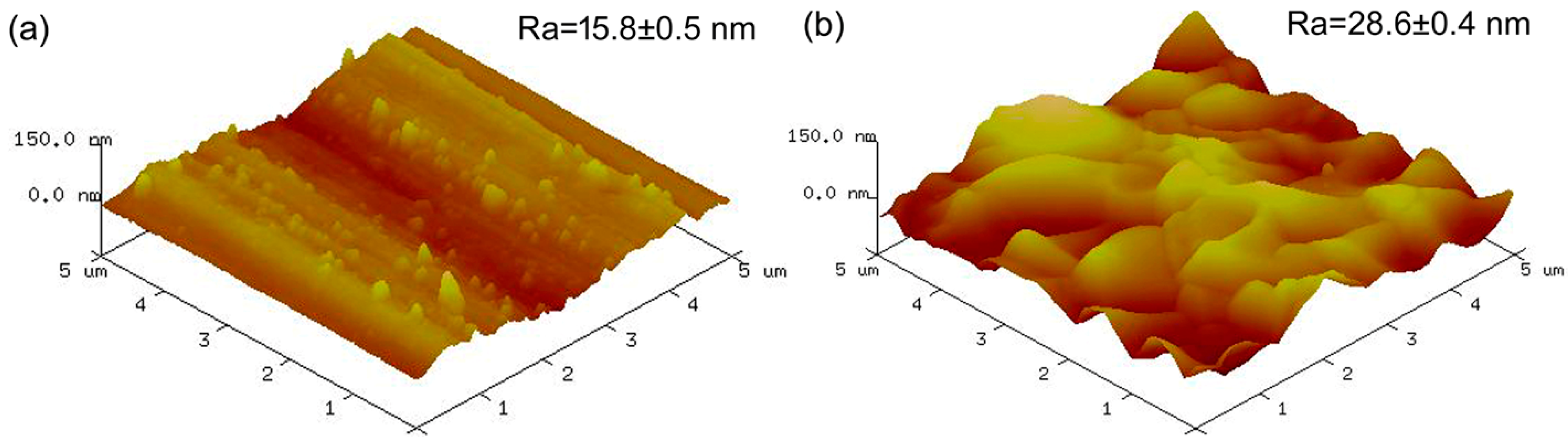
Figure 2 presents the AFM images and corresponding Ra values of ZK60 and Fe-Zr-ZK60 samples. It is seen in Figure 2a that a relatively smooth surface can be found for the ZK60 sample and there are some parallel grooves and metallic scrapings caused by mechanical grinding. For the Fe-Zr-ZK60 sample, as shown in Figure 2b, lots of island-like protuberances are filled on the surface and these protuberances connect with each other to generate a rough and dense microstructure. Furthermore, the Ra value is increased from 15.8 ± 0.5 nm for the ZK60 sample to 28.6 ± 0.4 nm for the Fe-Zr-ZK60 sample. The enhancement in surface fluctuation can be ascribed to two synergetic effects of ion bombardment and protuberances aggregation [32].
The cross-sectional BSE micrograph and corresponding EDX line-scan result of Fe-Zr-ZK60 sample are displayed in Figure 3. It is seen in Figure 3a that a uniform Fe/Zr composite coating with a thickness of 8.4 μm is deposited on the surface of ZK60 sample. At higher magnification shown in Figure 3b, the coating exhibits a bi-layer microstructure which is caused by the two continuous processes of Zr II&D and Fe II&D. The interface between Fe/Zr coating and ZK60 substrate is dense and compact without micro-hole defects. As shown in Figure 3c, the Fe/Zr coating is divided into two parts of outer Fe-modified layer and inner Zr-modified layer based on the elemental distributions of Fe, Zr and Mg. In the Fe-modified layer, lying within the depth of 4.6 μm, the Fe and Mg contents increase linearly with increasing depth and no Zr element is detected. In the Zr-modified layer between 4.6 and 8.4 μm, the Zr exhibits a Gaussian-like distribution. The Fe content firstly increases from 4.6 to 5.2 μm and then sharply decreases to zero at the depth of 8.4 μm. The Mg content shows an opposite trend compared with that of Fe. Similar elemental distribution can also be found in reference [33], where a continuous and smooth transition of Fe and Mg elements is formed across the intermediate layer of Fe II&D modified Mg alloy. It is concluded from Figure 1 and Figure 3 that a bi-layer Fe/Zr composite coating with outer Fe-modified layer and inner Zr-modified layer is generated by duplex Fe/Zr II&D, and the phase constitution of the coating is mainly composed of α-Fe phase and some metallic oxides.
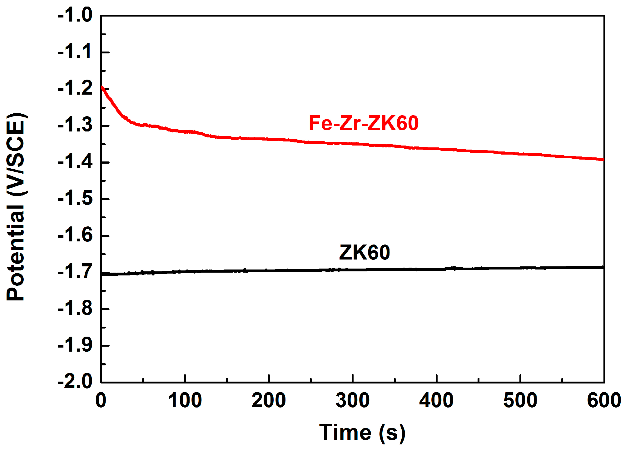
Figure 4 demonstrates the OCP curves of ZK60 and Fe-Zr-ZK60 samples in SBF at 37 °C. The OCP value of ZK60 sample increases slightly from −1.71 to −1.69 V/SCE during the 600 s immersion time (a small rising rate of 0.03 mV/s), meaning the surface has reached a stable state. Different from the ZK60 sample, an opposite trend in OCP curve is found for the Fe-Zr-ZK60 sample. The OCP value of Fe-Zr-ZK60 sample rapidly decreases from −1.19 to −1.29 V/SCE in the initial 35 s and then gradually becomes −1.39 V/SCE at the end of 600 s. In general, the drop and rise in OCP curve represent the breakdown and enhancement of passivation film, respectively. The surface passivation status in corrosive media is related to the phase composition: the passivation film of Mg phase grows slowly with increasing immersion time, while that of Fe phase dissolves in some degree as immersion time increases. Similar results have been reported in references [34,35], where the OCP curve of Mg-Zn-Mn alloy exhibited a positive shift and that of pure Fe showed a negative shift as the immersion time in Hank’s solution extended.
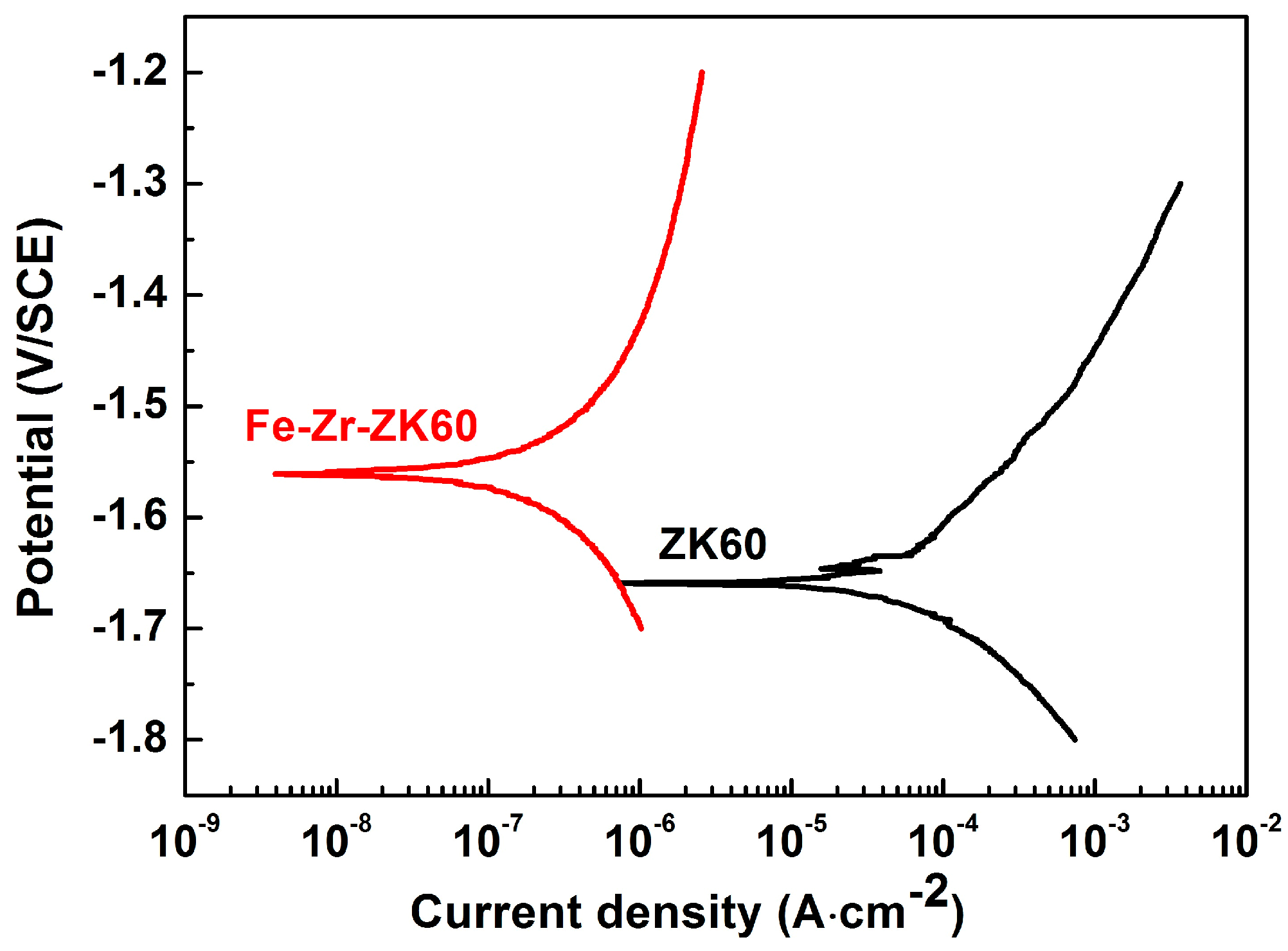
Figure 5 shows the potentiodynamic polarization curves of ZK60 and Fe-Zr-ZK60 samples in SBF at 37 °C and Table 2 summarizes the corresponding electrochemical parameters. The anodic branch represents the dissolution of metal by oxidation and the cathodic branch describes the hydrogen evolution via water reduction. The Ecorr and icorr are fitted by Tafel extrapolation in the cathodic polarization branch because of the negative difference effect of Mg alloys [36]. Usually, Ecorr implies the anti-corrosion ability on the surface and icorr suggests the corrosion rate once the passivation film is breakdown. The combination of larger Ecorr and smaller icorr indicates an enhanced corrosion resistance. The Ecorr and icorr of ZK60 sample are −1.66 ± 0.03 V/SCE and 112.3 ± 12.2 μA·cm−2, respectively. The Ecorr of Fe-Zr-ZK60 sample, being the mixed potential of Fe/Zr coating and ZK60 substrate, exhibits a positive shift of 100 mV to −1.56 ± 0.02 V/SCE. The icorr of Fe-Zr-ZK60 sample is greatly reduced to 0.34 ± 0.02 μA·cm−2, which shows an approximate 330-fold decrease compared with that of ZK60 sample. Furthermore, the βc value of Fe-Zr-ZK60 sample (−0.22 ± 0.01 V·decade−1) is smaller than that of ZK60 sample (−0.17 ± 0.03 V·decade−1), demonstrating a higher polarization resistance is found for the Fe-Zr-ZK60 sample. Jamesh et al. [22] conducted Zr&O plasma ion implantation on the ZK60 Mg alloy and the surface-modified sample possessed similar Ecorr of −1.57 ± 0.03 V/SCE and larger icorr of 11 ± 39 μA·cm−2 in comparison with the Fe-Zr-ZK60 sample under same corrosion conditions, indicating a better corrosion resistance can be obtained by duplex Fe/Zr II&D. The Fe/Zr composite coating with dense and compact morphology can serve as a physical barrier to protect the substrate from exposure to corrosive media, which suppresses the galvanic corrosion between α-Mg phase and MgZn2 secondary phases on the ZK60 sample surface and results in an enhanced corrosion resistance [37].
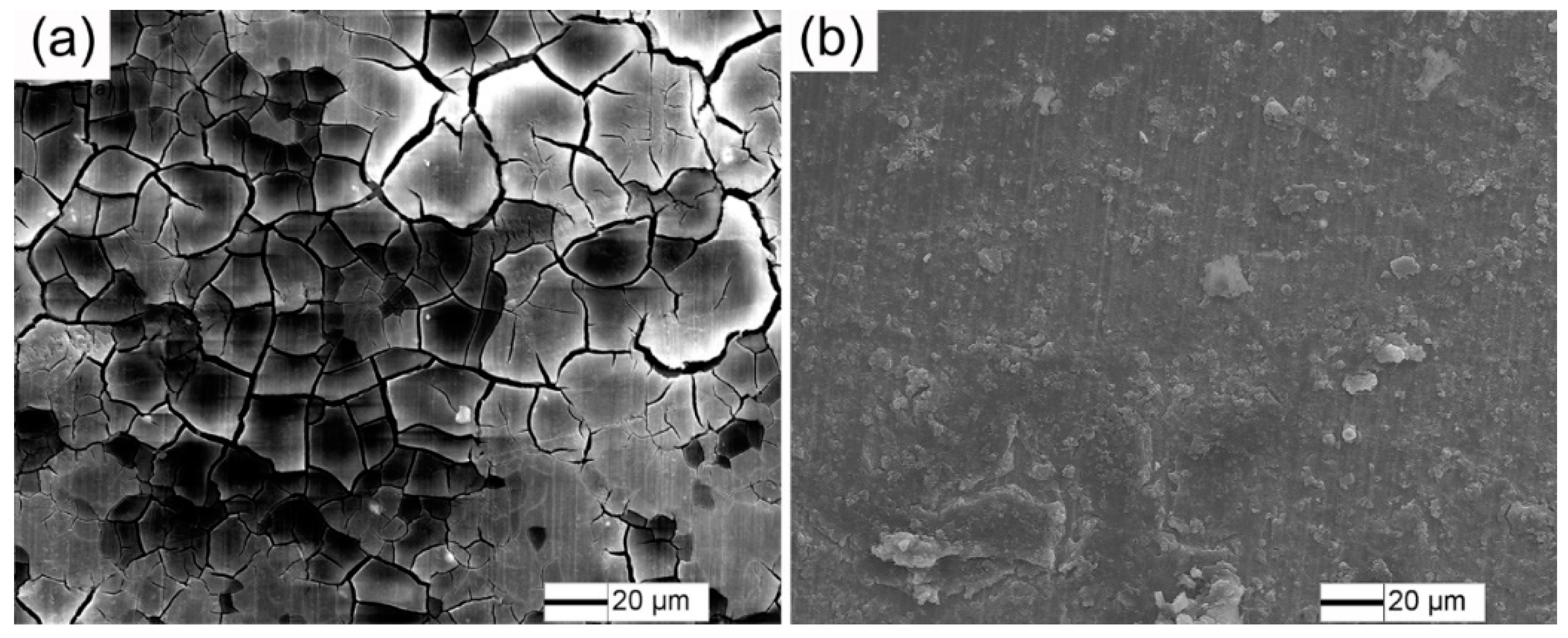
The surface morphology of ZK60 and Fe-Zr-ZK60 samples after potentiodynamic polarization tests in SBF at 37 °C are exhibited in Figure 6. It is seen in Figure 6a that the ZK60 sample is severely corroded to form discrete corrosion morphology and the surface is filled with large amount of web-like corrosion cracks. Figure 6b shows that the surface of Fe-Zr-ZK60 sample remains relatively intact without distinct corrosion area and there only appear some randomly distributed corrosion products. The electrochemical results indicate that the corrosion resistance of ZK60 sample is improved by the Fe/Zr composite coating.
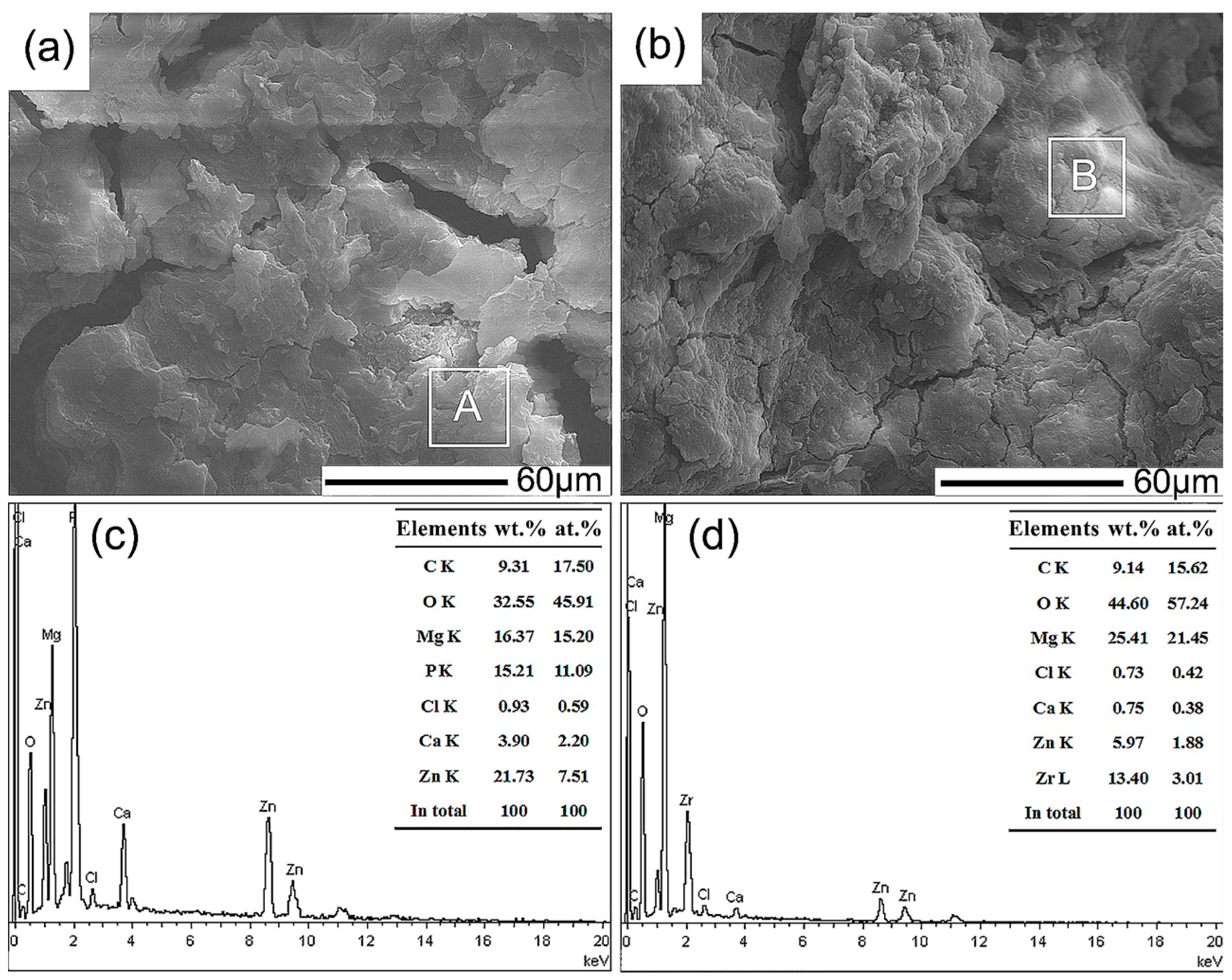
Figure 7 displays the surface micrographs and corresponding EDX results of ZK60 and Fe-Zr-ZK60 samples after immersion in SBF at 37 °C for 1 day. The surface of ZK60 sample, as shown in Figure 7a, is characterized by plate-like corrosion products and large corrosion cracks. The corrosion cracks, formed by water loss of corrosion products and surface shrinkage, can provide penetration channels for corrosive media to further corrode the ZK60 sample substrate [38]. For the Fe-Zr-ZK60 sample shown in Figure 7b, the corrosion degree on the surface is relatively low and the cluster-like corrosion products exhibit a compact microstructure with a few small corrosion cracks. In Figure 7c, the corrosion products marked by zone A of ZK60 sample are composed of 9.31 C, 32.55 O, 16.37 Mg, 15.21 P, 0.93 Cl, 3.90 Ca and 21.73 Zn (in wt.%), which may be inferred as carbon and Ca-P compounds (Ca/P = 0.26). The detection of O element is due to the oxidation process of Mg alloy. In Figure 7d, the corrosion products marked by zone B of Fe-Zr-ZK60 sample consist of 9.14 C, 44.60 O, 25.14 Mg, 0.73 Cl, 0.75 Ca, 5.97 Zn and 13.40 Zr (in wt.%). It is noted that no Fe and high Zr elements are left on the Fe-Zr-ZK60 sample surface, suggesting that the outer Fe-modified layer is dissolved with some inner Zr-modified layer remains after 1 day immersion time.
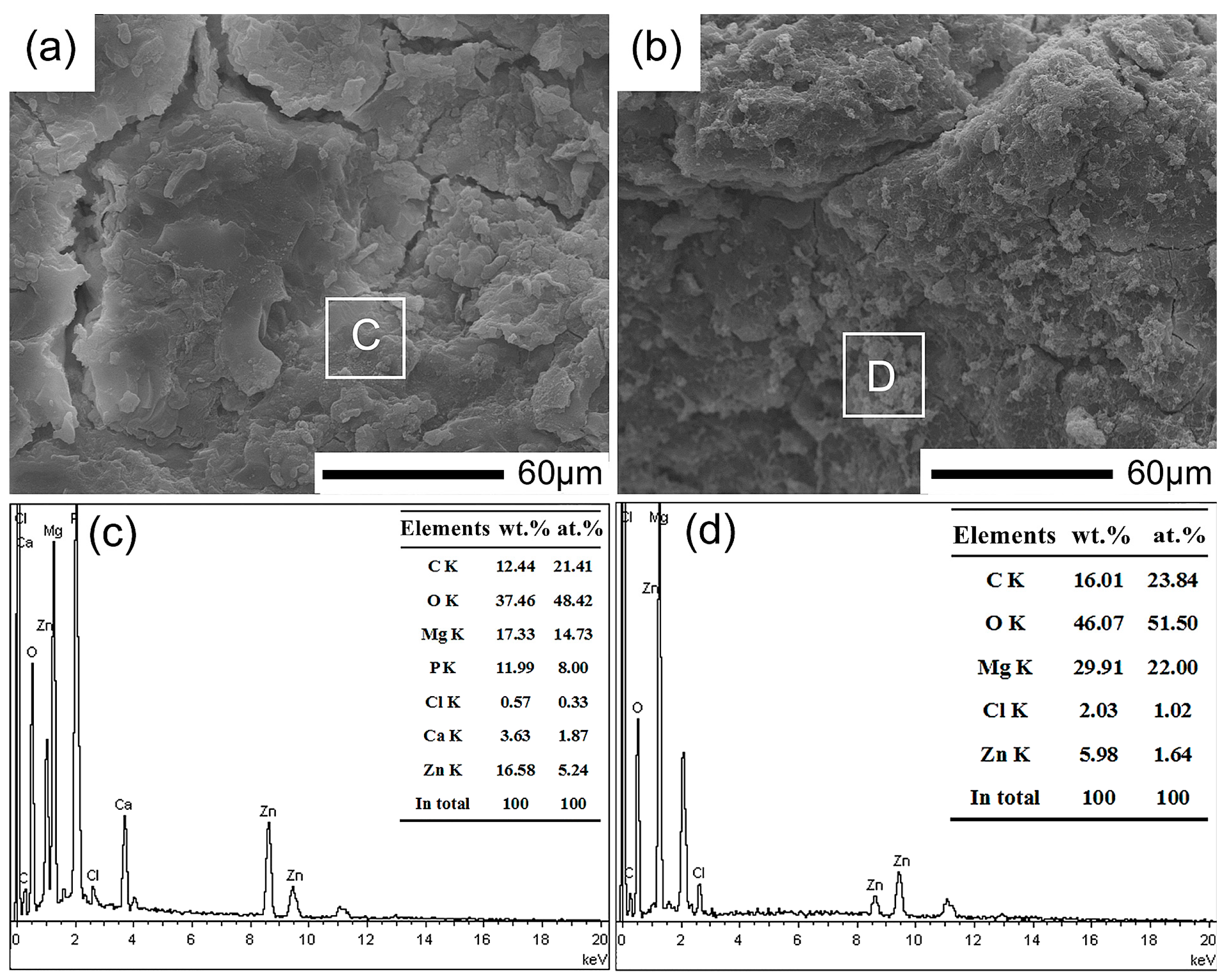
Figure 8 shows the surface micrographs and corresponding EDX results of ZK60 and Fe-Zr-ZK60 samples after immersion in SBF at 37 °C for 3 days. In Figure 8a, higher density corrosion cracks are present on the ZK60 sample surface. The corroded surface of Fe-Zr-ZK60 sample is compactly covered by thick corrosion products with tiny corrosion cracks, as seen in Figure 8b. The corrosion products on ZK60 sample surface, marked by zone C in Figure 8c, contain higher content of C, O, Mg and larger Ca/P ratio (0.30) compared with those formed after 1 day immersion (Figure 7c). In Figure 8d, no Zr element and higher content of C, O and Mg are detected in zone D than those in zone B (Figure 7d), indicating that the inner Zr-modified layer is exfoliated by SBF after 3 days immersion. The corrosion degree of ZK60 and Fe-Zr-ZK60 samples further aggravates as the immersion time increases.
The surface micrographs and corresponding EDX results of ZK60 and Fe-Zr-ZK60 samples after immersion in SBF at 37 °C for 7 days are presented in Figure 9. Figure 9a shows that the corrosion products of ZK60 sample become highly crystallized to form a compact layer on the surface with several small corrosion cracks. The Ca/P ratio of corrosion products marked by zone E (Figure 9c) further increases to 0.43, as is calculated by EDX results. In Figure 9b, the surface of Fe-Zr-ZK60 sample become rough and exhibits needle-like microstructure at higher magnification. The needle-like corrosion products contain relatively high Cl content (3.95 wt.%), which are speculated as MgCl2 phase [39]. The Fe-Zr-ZK60 sample surface (zone F in Figure 9d) has higher Mg content and lower O content compared with zone D in Figure 8d, indicating the corrosion products layer has some blocking effect for corrosive media and thus retards the corrosion rate of substrate. In addition, the pH value of SBF for ZK60 sample increases from 7.40 to 8.23 ± 0.08 (1 day), 8.91 ± 0.05 (3 days) and 9.60 ± 0.06 (7 days); while it increases from 7.40 to 7.82 ± 0.06 (1 day), 8.40 ± 0.12 (3 days) and 9.00 ± 0.09 (7 days) for Fe-Zr-ZK60 sample. The alkalization of SBF can be explained as follows [40]: the magnesium hydroxide (Mg(OH)2) firstly formed in SBF through the reaction of Mg + H2O = Mg(OH)2 + H2 and then was dissolved by Cl− into soluble MgCl2, releasing extra OH− and increasing the pH value. It is noted that a smaller pH value is observed for the Fe-Zr-ZK60 sample than ZK60 sample at each immersion time, which may be attributed to the lower corrosion rate of Fe-Zr-ZK60 sample and less OH− was generated.
For quantitative analysis of corrosion process, the ImageJ 1.52a software is employed to measure the area fraction of corrosion cracks at each immersion time in Figure 7, Figure 8 and Figure 9, as is summarized in Table 3. The area fraction of corrosion cracks for both ZK60 and Fe-Zr-ZK60 samples decreases with increasing immersion time, suggesting the densification process of the corrosion products layer. Furthermore, the Fe-Zr-ZK60 sample exhibits smaller area fractions than those of ZK60 sample for all immersion times, which indicates a less corrosion degree is obtained for the Fe-Zr-ZK60 sample.
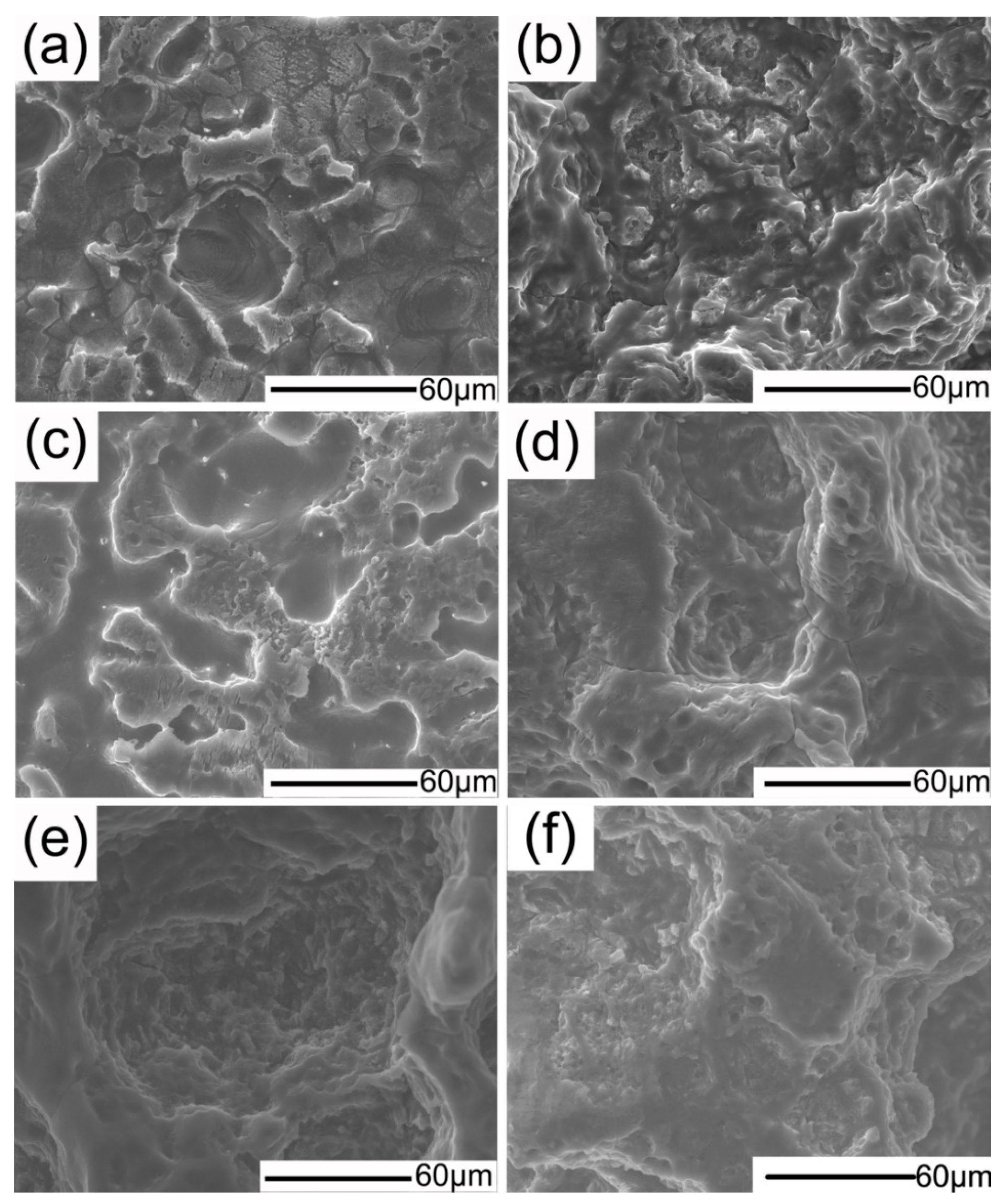
The corroded morphology without corrosion products of ZK60 and Fe-Zr-ZK60 samples at different immersion times in 37 °C SBF are demonstrated in Figure 10. In Figure 10a, lots of inhomogeneous corrosion pits and tiny holes caused by hydrogen evolution are observed on the ZK60 sample surface after 1 day immersion. Corrosion spreads across the entire surface of ZK60 sample and form a discrete morphology when the immersion time increases to 3 days, as seen in Figure 10c. The ZK60 sample surface is badly corroded at the end of 7 days immersion time, as is evidenced by the deep corrosion pits with a large size of around 70 μm in Figure 10e. Mild corrosion morphology is found for the Fe-Zr-ZK60 sample at each immersion time. In Figure 10b, the Fe-Zr-ZK60 sample exhibits a relatively integral surface and the corrosion pits is much smaller than those of ZK60 sample after 1 day immersion time. Figure 10d shows that the corrosion pits become larger and deeper after 3 days immersion time, suggesting that corrosion continues with increasing immersion time. However, the corrosion of Fe-Zr-ZK60 sample seems to be retarded when the immersion time increases to 7 days, as is seen from the similar corroded morphology between Figure 10f and Figure 10d. The suppression of corrosion may be ascribed to the dense corrosion products formed for 7 days immersion time (Figure 9b), which can block the penetration of corrosive media into the substrate and retard further corrosion. Therefore, the immersion tests results (Figure 7, Figure 8, Figure 9 and Figure 10) reveal that the corrosion resistance of ZK60 sample is moderately enhanced by duplex Fe/Zr II&D due to the compact Fe/Zr composite coating, which agrees well with the electrochemical tests (Figure 4, Figure 5 and Figure 6).
4. Conclusions
The corrosion behavior of ZK60 Mg alloy was surface modified by duplex Fe/Zr II&D. The results showed that a bi-layer Fe/Zr composite coating of outer Fe-modified layer (4.6 μm) and inner Zr-modified layer (3.8 μm) was formed. The phase constitution on the modified surface was mainly composed of α-Fe and a small amount of ZrO0.35 and Zr6Fe3O phases. The corrosion resistance of ZK60 Mg alloy was improved by the duplex Fe/Zr II&D due to the compact morphology and multi-phases microstructure on the surface. An approximate 100 mV elevation in Ecorr and 330-fold decrease in icorr were obtained for the surface-modified ZK60 Mg alloy.
Author Contributions
Conceptualization, Y.Z.; Investigation, Y.Z., L.Z. and Y.B.; Writing-Original Draft Preparation, Y.Z.; Writing-Review and Editing, Y.Z., L.Z. and Y.C.; Funding Acquisition, Y.L.; Supervision, Y.L.
Funding
This work is supported by the National Natural Science Foundation of China (NSFC, No. 51431002).
Acknowledgments
The authors thank Prof. Huixing Zhang at Beijing Normal University for the expert technical assistance with the Fe/Zr composite coating procedure.
Conflicts of Interest
The authors declare no conflict of interest.
References
- Kraus, T.; Fischerauer, S.; Treichler, S.; Martinelli, E.; Eichler, J.; Myrissa, A.; Zötsch, S.; Uggowitzer, P.J.; Löffler, J.F.; Weinberg, A.M. The influence of biodegradable magnesium implants on the growth plate. Acta Biomater. 2017, 66, 109–117. [Google Scholar] [CrossRef] [PubMed]
- Im, S.H.; Jung, Y.; Kim, S.H. Current status and future direction of biodegradable metallic and polymeric vascular scaffolds for next-generation stents. Acta Biomater. 2017, 60, 3–22. [Google Scholar] [CrossRef] [PubMed]
- Agarwal, S.; Curtin, J.; Duffy, B.; Jaiswal, S. Biodegradable magnesium alloys for orthopaedic applications: A review on corrosion, biocompatibility and surface modifications. Mater. Sci. Eng. C 2016, 68, 948–963. [Google Scholar] [CrossRef] [PubMed] [Green Version]
- Witte, F.; Hort, N.; Vogt, C.; Cohen, S.; Kainer, K.U.; Willumeit, R.; Feyerabend, F. Degradable biomaterials based on magnesium corrosion. Curr. Opin. Solid State Mater. Sci. 2008, 12, 63–72. [Google Scholar] [CrossRef]
- Janning, C.; Willbold, E.; Vogt, C.; Nellesen, J.; Meyer-Lindenberg, A.; Windhagen, H.; Thorey, F.; Witte, F. Magnesium hydroxide temporarily enhancing osteoblast activity and decreasing the osteoclast number in peri-implant bone remodeling. Acta Biomater. 2010, 6, 1861–1868. [Google Scholar] [CrossRef] [PubMed]
- Staiger, M.P.; Pietak, A.M.; Huadmai, J.; Dias, G. Magnesium and its alloys as orthopedic biomaterials: A review. Biomaterials 2006, 27, 1728–1734. [Google Scholar] [CrossRef] [PubMed]
- Person, M.; Torgersen, J.; Berto, F. Mg and its alloys for biomedical applications: Exploring corrosion and its interplay with mechanical failure. Metals 2017, 7, 252. [Google Scholar] [CrossRef]
- Pezzato, L.; Vranescu, D.; Sinico, M.; Gennari, C.; Settimi, A.G.; Pranovi, P.; Brunelli, K.; Dabalà, M. Tribocorrosion properties of PEO coatings produced on AZ91 magnesium alloy with silicate- or phosphate-based electrolytes. Coatings 2018, 8, 202. [Google Scholar] [CrossRef]
- Upadhyay, V.; Bergseth, Z.; Kelly, B.; Battocchi, D. Silica-based sol-gel coating on magnesium alloy with green inhibitors. Coatings 2017, 7, 86. [Google Scholar] [CrossRef]
- Zhu, B.W.; Wang, S.M.; Wang, L.; Yang, Y.; Liang, J.; Cao, B.C. Preparation of hydroxyapatite/tannic acid coating to enhance the corrosion resistance and cytocompatibility of AZ31 magnesium alloys. Coatings 2017, 7, 105. [Google Scholar] [CrossRef]
- Asri, R.I.M.; Harun, W.S.W.; Samykano, M.; Lah, N.A.C.; Ghani, S.A.C.; Tarlochan, F.; Raza, M.R. Corrosion and surface modification on biocompatible metals: A review. Mater. Sci. Eng. C 2017, 77, 1261–1274. [Google Scholar] [CrossRef] [PubMed]
- Zhang, D.F.; Wei, B.B.; Wu, Z.T.; Qi, Z.B.; Wang, Z.C. A comparative study on the corrosion behavior of Al, Ti, Zr and Hf metallic coatings deposited on AZ91D magnesium alloys. Surf. Coat. Technol. 2016, 303, 94–102. [Google Scholar] [CrossRef]
- Jin, W.H.; Wang, G.M.; Lin, Z.J.; Feng, H.Q.; Li, W.; Peng, X.; Qasim, A.M.; Chu, P.K. Corrosion resistance and cytocompatibility of tantalum-surface-functionalized biomedical ZK60 Mg alloy. Corros. Sci. 2016, 114, 45–56. [Google Scholar] [CrossRef]
- Ba, Z.X.; Dong, Q.S.; Yin, J.H.; Wang, J.X.; Ma, B.; Zhang, X.B.; Wang, Z.Z. Surface properties of Mg-Gd-Zn-Zr alloy modified by Sn ion implantation. Mater. Lett. 2016, 190, 90–94. [Google Scholar] [CrossRef]
- Guo, S.F.; Pan, F.S.; Zhang, H.J.; Zhang, D.F.; Wang, J.F.; Miao, J.; Su, C.; Zhang, C. Fe-based amorphous coating for corrosion protection of magnesium alloy. Mater. Des. 2016, 108, 624–631. [Google Scholar] [CrossRef]
- Fu, Z.X.; Chen, X.; Liu, B.; Liu, J.; Han, X.P.; Deng, Y.D.; Hu, W.B.; Zhong, C. One-step fabrication and localized electrochemical characterization of continuous Al-alloyed intermetallic surface layer on magnesium alloy. Coatings 2018, 8, 148. [Google Scholar] [CrossRef]
- Anders, A. Metal plasma immersion ion implantation and deposition: A review. Surf. Coat. Technol. 1997, 93, 158–167. [Google Scholar] [CrossRef]
- Jabbari, Y.S.A.; Fehrman, J.; Barnes, A.C.; Zapf, A.M.; Zinelis, S.; Berzins, D.W. Titanium nitride and nitrogen ion implanted coated dental materials. Coatings 2012, 2, 160–178. [Google Scholar] [CrossRef]
- Liu, C.L.; Xin, Y.C.; Tian, X.B.; Chu, P.K. Corrosion behavior of AZ91 magnesium alloy treated by plasma immersion ion implantation and deposition in artificial physiological fluids. Thin Solid Films 2007, 516, 422–427. [Google Scholar] [CrossRef] [Green Version]
- Liu, J.; Zheng, Y.; Bi, Y.Z.; Li, Y.; Zheng, Y.F. Improved cytocompatibility of Mg-1Ca alloy modified by Zn ion implantation and deposition. Mater. Lett. 2017, 205, 87–89. [Google Scholar] [CrossRef]
- Schinhammer, M.; Hänzi, A.C.; Löffler, J.F.; Uggowitzer, P.J. Design strategy for biodegradable Fe-based alloys for medical applications. Acta Biomater. 2009, 6, 1705–1713. [Google Scholar] [CrossRef] [PubMed]
- Jamesh, M.I.; Wu, G.S.; Zhao, Y.; McKenzie, D.R.; Bilek, M.M.M.; Chu, P.K. Effects of zirconium and oxygen plasma ion implantation on the corrosion behavior of ZK60 Mg alloy in simulated body fluids. Corros. Sci. 2014, 82, 7–26. [Google Scholar] [CrossRef]
- Liu, L.; Xiao, L.; Feng, J.; Li, L.; Esmaeili, S.; Zhou, Y. Bonding of immiscible Mg and Fe via a nanoscale Fe2Al5 transition layer. Scr. Mater. 2011, 65, 982–985. [Google Scholar] [CrossRef]
- Kokubo, T.; Takadama, H. How useful is SBF in predicting in vivo bone bioactivity? Biomaterials 2006, 27, 2907–2915. [Google Scholar] [CrossRef] [PubMed]
- Xu, R.Z.; Yang, X.B.; Li, P.H.; Suen, K.W.; Wu, G.S.; Chu, P.K. Electrochemical properties and corrosion resistance of carbon-ion-implanted magnesium. Corros. Sci. 2014, 82, 173–179. [Google Scholar] [CrossRef]
- Chen, X.B.; Nisbet, D.R.; Li, R.W.; Smith, P.N.; Abbott, T.B.; Easton, M.A.; Zhang, D.H.; Birbilis, N. Controlling initial biodegradation of magnesium by a biocompatible strontium phosphate conversion coating. Acta Biomater. 2014, 10, 1463–1474. [Google Scholar] [CrossRef] [PubMed]
- ASTM Standard G31-72 Standard Practice for Laboratory Immersion Corrosion Testing of Metals; ASTM International: West Conshohocken, PA, USA, 2004.
- Zheng, Y.; Li, Y.; Chen, J.H.; Zou, Z.Y. Effects of tensile and compressive deformation on corrosion behavior of a Mg-Zn alloy. Corros. Sci. 2015, 90, 445–450. [Google Scholar] [CrossRef]
- Li, C.X.; Yu, Y.D. The effect of solution heat treatments on the microstructure and hardness of ZK60 magnesium alloys prepared under low-frequency alternating magnetic fields. Mater. Sci. Eng. A 2013, 559, 22–28. [Google Scholar] [CrossRef]
- Liu, B.; Zheng, Y.F. Effects of alloying elements (Mn, Co, Al, W, Sn, B, C and S) on biodegradability and in vitro biocompatibility of pure iron. Acta Biomater. 2011, 7, 1407–1420. [Google Scholar] [CrossRef] [PubMed]
- Zhao, T.T.; Li, Y.; Zhao, X.Q.; Chen, H.; Zhang, T. Ni ion release, osteoblasts-materials interactions and hemocompatibility of hafnium implanted NiTi alloy. J. Biomed. Mater. Res. B 2012, 100B, 646–659. [Google Scholar] [CrossRef] [PubMed]
- Zhao, T.T.; Li, Y.; Xiang, Y.; Zhao, X.Q.; Zhang, T. Surface characteristics, nano-indentation and corrosion behavior of Nb implanted NiTi alloy. Surf. Coat. Technol. 2011, 205, 4404–4410. [Google Scholar] [CrossRef]
- Zheng, Y.; Li, Y.; Chen, J.H.; Zou, Z.Y. Surface characteristics and corrosion resistance of ZK60 magnesium alloy modified by Fe ion implantation and deposition. Prog. Nat. Sci. Mater. 2014, 24, 547–553. [Google Scholar] [CrossRef]
- He, W.W.; Zhang, E.L.; Yang, K. Effect of Y on the bio-corrosion behavior of extruded Mg-Zn-Mn alloy in Hank’s solution. Mater. Sci. Eng. C 2010, 30, 167–174. [Google Scholar] [CrossRef]
- Zhang, E.L.; Chen, H.Y.; Shen, F. Biocorrosion properties and blood and cell compatibility of pure iron as a biodegradable biomaterial. J. Mater. Sci. Mater. Med. 2010, 21, 2151–2163. [Google Scholar] [CrossRef] [PubMed]
- McCafferty, E. Validation of corrosion rates measured by the Tafel extrapolation method. Corros. Sci. 2005, 47, 3202–3215. [Google Scholar] [CrossRef]
- Bakhsheshi-Rad, H.R.; Hamzah, E.; Kasiri-Asgarani, M.; Jabbarzare, S.; Iqbal, N.; Abdul-kadir, M.R. Deposition of nanostructured fluorine-doped hydroxyapatite-polycaprolactone duplex coating to enhance the mechanical properties and corrosion resistance of Mg alloy for biomedical applications. Mater. Sci. Eng. C 2016, 60, 526–537. [Google Scholar] [CrossRef] [PubMed]
- Bakhsheshi-Rad, H.R.; Hamzah, E.; Daroonparvar, M.; Saud, S.N.; Abdul-kadir, M.R. Bi-layer nano-TiO2/FHA composite coatings on Mg-Zn-Ce alloy prepared by combined physical vapour deposition and electrochemical deposition methods. Vacuum 2014, 110, 127–135. [Google Scholar] [CrossRef]
- Jang, Y.; Collins, B.; Sankar, J.; Yun, Y. Effect of biologically relevant ions on the corrosion products formed on alloy AZ31B: An improved understanding of magnesium corrosion. Acta Biomater. 2013, 9, 8761–8770. [Google Scholar] [CrossRef] [PubMed]
- Zhang, S.X.; Li, J.N.; Song, Y.; Zhao, C.L.; Zhang, X.N.; Xie, C.Y.; Zhang, Y.; Tao, H.R.; He, Y.H.; Jiang, Y.; et al. In vitro degradation, hemolysis and MC3T3-E1 cell adhesion of biodegradable Mg-Zn alloy. Mater. Sci. Eng. C 2009, 29, 1907–1912. [Google Scholar] [CrossRef]
Figure 1.
XRD patterns of ZK60 and Fe-Zr-ZK60 samples.

Figure 2.
AFM images and corresponding Ra values of (a) ZK60 and (b) Fe-Zr-ZK60 samples.

Figure 3.
Cross-sectional BSE micrograph of the Fe-Zr-ZK60 sample at (a) low, and (b) high magnifications; and (c) corresponding EDX line-scan result.
Figure 3.
Cross-sectional BSE micrograph of the Fe-Zr-ZK60 sample at (a) low, and (b) high magnifications; and (c) corresponding EDX line-scan result.
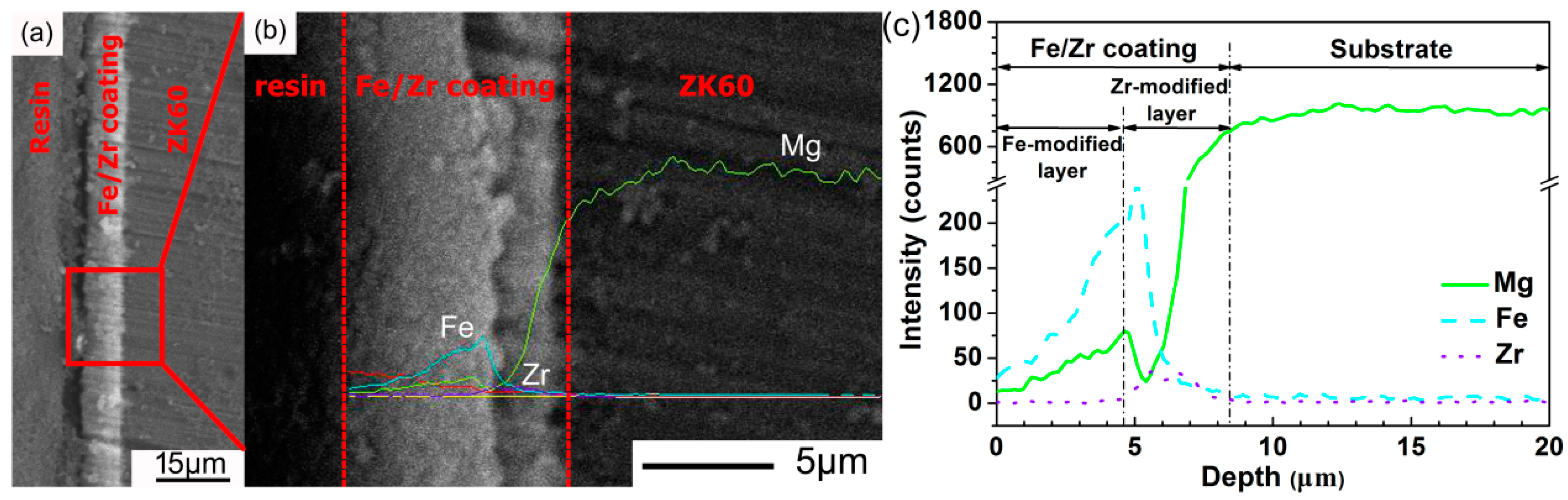
Figure 4.
OCP curves of ZK60 and Fe-Zr-ZK60 samples in SBF at 37 °C.

Figure 5.
Potentiodynamic polarization curves of ZK60 and Fe-Zr-ZK60 samples in SBF at 37 °C.

Figure 6.
Surface morphology of (a) ZK60 and (b) Fe-Zr-ZK60 samples after potentiodynamic polarization tests in SBF at 37 °C.
Figure 6.
Surface morphology of (a) ZK60 and (b) Fe-Zr-ZK60 samples after potentiodynamic polarization tests in SBF at 37 °C.

Figure 7.
Surface micrographs of (a) ZK60 and (b) Fe-Zr-ZK60 samples in SBF at 37 °C for 1 day; the EDX results of zone A and B are shown in (c,d), respectively.
Figure 7.
Surface micrographs of (a) ZK60 and (b) Fe-Zr-ZK60 samples in SBF at 37 °C for 1 day; the EDX results of zone A and B are shown in (c,d), respectively.

Figure 8.
Surface micrographs of (a) ZK60 and (b) Fe-Zr-ZK60 samples in SBF at 37 °C for 3 days; the EDX results of zone C and D are shown in (c,d), respectively.
Figure 8.
Surface micrographs of (a) ZK60 and (b) Fe-Zr-ZK60 samples in SBF at 37 °C for 3 days; the EDX results of zone C and D are shown in (c,d), respectively.

Figure 9.
Surface micrographs of (a) ZK60 and (b) Fe-Zr-ZK60 samples in SBF at 37 °C for 7 days; the EDX results of zone E and F are shown in (c,d), respectively.
Figure 9.
Surface micrographs of (a) ZK60 and (b) Fe-Zr-ZK60 samples in SBF at 37 °C for 7 days; the EDX results of zone E and F are shown in (c,d), respectively.
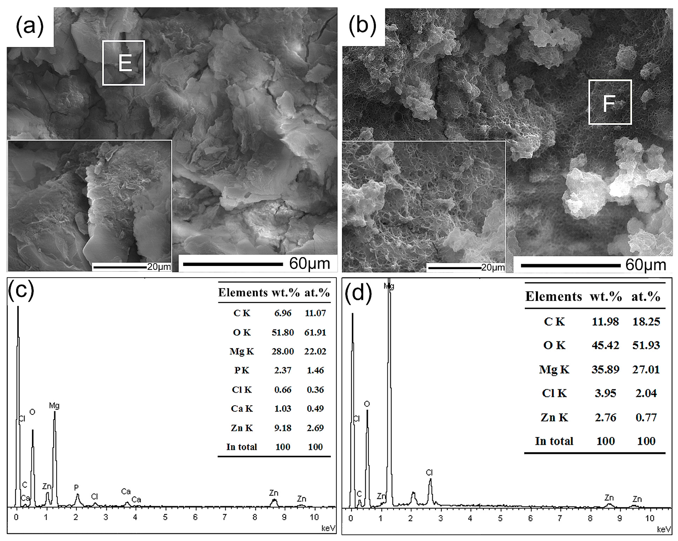
Figure 10.
SEM images of the corroded morphology of (a,c,e) ZK60 and (b,d,f) Fe-Zr-ZK60 samples immersed in SBF at 37 °C for (a,b) 1 day, (c,d) 3 days and (e,f) 7 days, respectively. The corrosion products were removed using 200 g·L−1 CrO3 solution.
Figure 10.
SEM images of the corroded morphology of (a,c,e) ZK60 and (b,d,f) Fe-Zr-ZK60 samples immersed in SBF at 37 °C for (a,b) 1 day, (c,d) 3 days and (e,f) 7 days, respectively. The corrosion products were removed using 200 g·L−1 CrO3 solution.


Table 1.
Processing parameters of duplex Fe/Zr II&D.
| Source | Implantation Process | Deposition Process | |||||||
|---|---|---|---|---|---|---|---|---|---|
| Voltage (kV) | Current (mA) | Dose (Ions/cm2) | Time (s) | Striking Current (A) | Bias Voltage (V) | Current (mA) | Electric Quantity (mC) | Time (s) | |
| Zr | 10 | 6 | 1 × 10¹⁶ | 160 | 150 | −150 | 500 | 6 × 10⁵ | 1200 |
| Fe | 4 | 2 | 2.4 × 10¹⁷ | 6000 | 110 | −100 | 500 | 1.6 × 10⁶ | 3200 |
Table 2.
Electrochemical parameters of ZK60 and Fe-Zr-ZK60 samples fitted from the potentiodynamic polarization curves.
Table 2.
Electrochemical parameters of ZK60 and Fe-Zr-ZK60 samples fitted from the potentiodynamic polarization curves.
| Sample | Ecorr (V/SCE) | icorr (μA·cm−2) | βc (V·decade−1) |
|---|---|---|---|
| ZK60 | −1.66 ± 0.03 | 112.3 ± 12.2 | −0.17 ± 0.03 |
| Fe-Zr-ZK60 | −1.56 ± 0.02 | 0.34 ± 0.02 | −0.22 ± 0.01 |
Table 3.
The area fractions of corrosion cracks on the sample surfaces at each immersion time.
| Samples | Area Fraction (%) | ||
|---|---|---|---|
| 1 Day | 3 Days | 7 Days | |
| ZK60 | 9.74 | 4.97 | 2.55 |
| Fe-Zr-ZK60 | 5.85 | 1.98 | 0.97 |
© 2018 by the authors. Licensee MDPI, Basel, Switzerland. This article is an open access article distributed under the terms and conditions of the Creative Commons Attribution (CC BY) license (http://creativecommons.org/licenses/by/4.0/).
Share and Cite
MDPI and ACS Style
Zheng, Y.; Zang, L.; Bi, Y.; Li, Y.; Chen, Y. Corrosion Behavior of Fe/Zr Composite Coating on ZK60 Mg Alloy by Ion Implantation and Deposition. Coatings 2018, 8, 261. https://doi.org/10.3390/coatings8080261
AMA Style
Zheng Y, Zang L, Bi Y, Li Y, Chen Y. Corrosion Behavior of Fe/Zr Composite Coating on ZK60 Mg Alloy by Ion Implantation and Deposition. Coatings. 2018; 8(8):261. https://doi.org/10.3390/coatings8080261
Chicago/Turabian StyleZheng, Yang, Libin Zang, Yanze Bi, Yan Li, and Yong Chen. 2018. "Corrosion Behavior of Fe/Zr Composite Coating on ZK60 Mg Alloy by Ion Implantation and Deposition" Coatings 8, no. 8: 261. https://doi.org/10.3390/coatings8080261
Note that from the first issue of 2016, this journal uses article numbers instead of page numbers. See further details here.