Thermal Spray Coatings of Al, ZnAl and Inconel 625 Alloys on SS304L for Anti-Saline Corrosion
by
 ,
,
Tung-Yuan Yung
1,*, 
Tai-Cheng Chen
1,
Kun-Cao Tsai
1,
Wen-Feng Lu
1,
Jiunn-Yuan Huang
1 and
Ting-Yu Liu
2,* 
1
Nuclear Fuels and Materials Division, Institute of Nuclear Energy Research, Taoyaun 32546, Taiwan
2
Department of Materials Engineering, Ming Chi University of Technology, New Taipei City 24301, Taiwan
*
Authors to whom correspondence should be addressed.
Coatings 2019, 9(1), 32; https://doi.org/10.3390/coatings9010032
Submission received: 12 September 2018
/
Revised: 26 November 2018
/
Accepted: 27 December 2018
/
Published: 8 January 2019
(This article belongs to the Special Issue Corrosion Characterization and Surface Analysis of Metallic Materials)
Abstract
:Stainless steel 304L (SS304L) has been selected as the material for canisters for spent fuel storage from three nuclear power plants in Taiwan. A crucial issue is extending the spent fuel storage safety standards of the canisters. The anti-saline corrosion abilities of three thermal spray coatings (i.e., Al, ZnAl, and 625 Inconel alloys) on the SS304L were evaluated by immersion in 3.5 wt % aqueous NaCl and with 0.025 g/cm2 NaCl deposition at 80 °C and 80% relative humidity (RH) for 1000 h. The pristine thermal spray coatings were examined using the pull-off adhesion test to understand the adhesion strength, and Vickers hardness was measured for the mechanical properties of the three coatings. Confocal laser scanning microscopy (CLSM) was used to identify the porosities of the coatings. Furthermore, the surfaces of the specimens before and after corrosion were investigated using scanning electron microscopy (SEM), X-ray diffraction (XRD), and energy dispersive spectroscopy (EDS). The composition and distribution of the oxide layers formed on the coating surfaces during corrosion were evaluated. Electrochemical measurement was also performed with the polarization method to quantify the corrosion property of the three thermal spray coatings. The results showed that the corrosion rate of Al coating was lowest from the Tafel analysis after the 1000 h corrosion test in 3.5% aqueous NaCl. In contrast, the corrosion rate of Inconel 625 was lowest after 1000 h of the NaCl deposition corrosion test in a controlled environment. Therefore, the ZnAl thermal spray coating is a potential protection layer, keeping in mind economic considerations, of SS304L for anti-corrosion in saline environments.
1. Introduction
Austenitic stainless steels are extensively used in the nuclear industry because of their good anti-rust performance in corrosive environments, in addition to excellent ductility, formability, toughness, and weldability. These structural steels are being used everywhere in the world for their inherent mechanical properties, but there are problems related to corrosion in aqueous and marine environments. However, the mechanical property and corrosion resistance of AISI 304 austenitic stainless steel (SS304L) has been reported to change with sensitization [1,2,3,4,5,6]. The storage facilities are located in coastal nuclear power plants in the Pacific-rim region, such as in South Korea, Japan, and Taiwan [7,8,9]. The implanted nitrogen ions and chromium-base coatings are reported for enhancing the anti-corrosion abilities in solution and in high temperatures [3]. The thermal spray coatings are used for long-term protection on the metal surfaces of structures such as aircrafts, bridges, and wind turbine towers. Although the canisters are protected with a concrete cask, stainless steels near shores are severely corroded worldwide. Chlorine susceptibility, common in austenitic stainless steels, is an inherent characteristic of SS304L. There are some known cases of stress corrosion cracking in the welding zone and heat-affected zone of the SS304L body near chlorine-containing environments. Chloride-induced stress corrosion cracking is a crucial issue [10,11,12].
Based on cost considerations, the most common method to improve corrosion resistance near shore construction metals is organic coating [13,14]. However, the coatings will degrade when they are exposed to sunlight (UV radiation), humidity, and a chlorine-containing atmosphere. The coating durability is approximately 3–5 years [15,16,17]. To enhance durability, some organic coatings are made to contain ZnAl or Al2O3 powder, which extends the durability to seven years [18,19,20]. Wire arc spray coating is an economical solution to improve the surface anti-corrosion resistance of metal surfaces, which provides various applications by changing the spraying variables, such as the temperature, velocity, and materials [19]. The arc-sprayed aluminum coating layer was reported to decrease the stress corrosion cracking susceptibility of 22% Cr duplex stainless steels by resisting the chemicals or corrosion inhibitors [20]. The electrochemical impedance spectroscopy (EIS) study of the aluminum coating on mild steels shows that the coated specimens had higher impedance values after 1500 h of the salt spray test. Thus, the impedance values can be related to the corrosion products or oxides that form on the coating surface [21]. Zinc coating applied by the pulsed air arc deposition (PAAD) decreases the corrosion rate of the low carbon steel substrate [22]. Alloy Inconel 625 is considered a good candidate for chlorine resistant coatings [23,24].
In this paper, we describe a recent investigation of the chlorine corrosion resistance properties of Al, ZnAl alloy (by arc spray), and Inconel 625 alloy (by high velocity oxygen fuel or HVOF) applied on the 304L stainless steel substrate in a chlorine-containing environment (i.e., 3.5 wt % aqueous NaCl at room temperature and 0.025 g/cm2 NaCl deposition in a controlled environment).
2. Experimental Procedure
The substrate was stainless steel 304L, which contains 0.03 wt % carbon and 18–20 wt % chromium. The alloy Inconel 625, which is rich in nickel and contains 22 wt % chromium, was purchased from PARAX Inc., Anaheim, CA, USA. The arc spray wires were also from PARAX. The element composition of Al is approximately 99.5 wt % aluminum, and the ZnAl alloy is 14–16 wt % aluminum.
2.1. Thermal Spray Process
Three commercially available arc spray wires were applied in this study; they were made of aluminum and 85/15 zinc–aluminum with a diameter of 1.6 mm. The coatings were deposited on a 10 mm thick SS304L plate using the EuTronic EAS-4 wire arc spray system (Castolin Eutectic, Lausanne, Switzerland). The Inconel Alloy 625 coatings were prepared with 30–50 m Inconel Alloy 625 particles at a feeding rate of 98 g/min (PRAXAIR TAFA Inconel 625 powder) at oxygen concentrations of 138 ± 10 psi and kerosene concentrations of 127 ± 10 psi with the PRAXAIR TAFA JP-5000 HVOF system (TAFA Inc., Nashville, TN, USA). To remove the rust and provide better bonding strength of the coatings, dry-sand blasting was used on the surface of the received SS304L substrate, purchased from the China Steel Company (Kaoshiung, Taiwan). The chemical composition of the materials analyzed with ICP-OES (PerkinElmer, Waltham, MA, USA) and thermal spray parameters are listed in Table 1 and Table 2, respectively. After the thermal spray process, the specimens were tested for corrosion by cutting the sprayed material into 20 × 20 mm2 samples on a water jet cutter. The high velocity oxygen-fuel coating was done according to the parameters in Table 2. This procedure was provided from PRAXAIR. Figure 1 shows the cross-sectional optical image to measure the thickness.
2.2. Coating Surface Characterization: Porosity, Bonding Strength, and Hardness
The cross-sectional microstructure of the coating layer was observed using a laser confocal scanning microscope (LCSM, 4000 LCSM, Olympus, Tokyo, Japan). Then, the porosity of the layer was calculated using ImageJ software (1.51v) with the depth profile of the LCSM image. The surface roughness was also measured with LCSM. The bonding strength of the coating layer was evaluated in the pull-off test using the universal testing system (MTS, Huntsville, AL, USA) in accordance with the ASTM C633-13 standard [25]. The Vickers hardness tester (HM-200, Mitutoyo, Kawasaki City, Japan) was used to characterize the hardness distribution from the coating layer to the substrate with 0.1 N of test force and a 15-s dwell time.
2.3. Corrosion Test
The corrosion test was conducted by immersing the sprayed specimens into a 3.5 wt % sodium chloride solution with a pH value of 5.5 at ambient temperature from 0 to 1000 h. After the corrosion test, the specimens were ultrasonically cleaned in acetone and dried in the oven for 12 h. The NaCl 0.025 g/cm2 deposition with corrosion test was executed in the environment control chamber at 80 °C and 80% RH for 1000 h. Five samples were tested for each corrosion condition.
2.4. Scanning Electron Microscopy and Energy Dispersive Spectroscopy (SEM/EDS)
The surface and cross-sectional morphologies of the corrosion specimens were observed using the JEOL JSM-7100F scanning electron microscope (SEM; JEOL, Tokyo, Japan). The variation elements of the corrosion specimens were characterized by Oxford Instrument X-Max energy dispersive spectroscopy (EDS; Oxford Instrument, Thames, UK).
2.5. X-Ray Diffractometer
The surface crystalline structures of the three coatings were examined with Bruker D8 Advanced (Bruker, Billerica, MA, USA) using Cu. The surfaces of the thermal coatings were evaluated before and after the corrosion test. The two scan range was 15°–80° with the locked couple method at the rate of one step per second.
2.6. Electrochemical Analyses
The electrochemical analysis was conducted by linear scan voltammetry (LSV) with 3.5 wt % aqueous NaCl at ambient temperature. The three-electrode test was used with the working electrode, which had a 10 mm2 corrosion surface in the electrolyte and the plate corrosion cell from BSA Inc. (Toyama, Japan). A 1 cm2 platinum foil was the counter electrode, and Ag/AgCl was the reference electrode. The test parameter was controlled by a computerized Autolab PSTAT 30 potentiostat (Metrohm AG, Herisau, Switzerland) with a scan rate of 10 mV/s and scan ranges from −1.0 to 1.0 V (for Al and ZnAl coatings) and from −0.6 to 1.0 V (for 625 coatings). The corrosion potential (Ecorr) and corrosion current density (jcorr) were determined by Tafel equation based on the LSV results. The corrosion rate (mils per year or MPY) was calculated as follows:
where A is the active area and d is the density of the sample.
3. Results and Discussion
3.1. Mechanical Properties and Surface Morphology of Thermal Spray Coatings
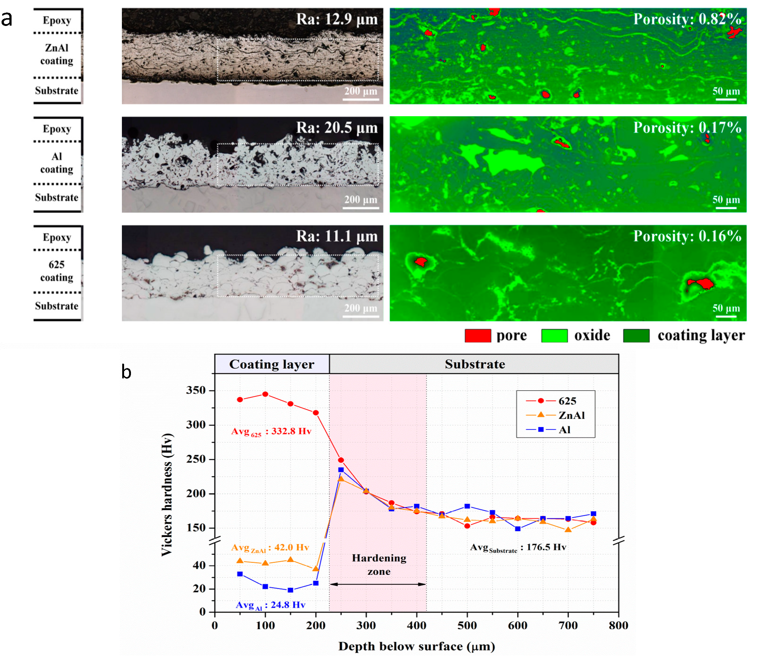
The cross-sectional specimens of three arc spray coatings reveal the porosity of the coating layers. The sprayed specimens mainly exhibit a laminar structure with some oxide and pores inside. Figure 1 shows that the ZnAl layers have the lowest porosity, and the Al alloy layer has the highest porosity. The Al arc spray layer has the lowest hardness among three arc spray coatings, as shown in Figure 1d. The blast process increased the hardness and surface roughness, as shown in Figure 1d. The ZnAl, Al, and Inconel 625 coating layers exhibit the bulk properties of the coating layers with average micro-hardness values of 42.0, 24.8, and 332.8 HV, respectively. The Inconel 625 alloy arc-spray layer has the greatest hardness among the three coatings. In Table 3, the adhesion strengths of the three arc spray coatings are in the order of Inconel 625 > Al > ZnAl, with the values of 36.4 ± 3.5, 10.8 ± 1.5, and 11 ± 2.0 MPa, respectively. After the SS304L surface was blasted, the mechanical properties indicate that the Inconel 625 alloy coating is the best of the three types.
Figure 2a shows the surface of the thermal spray coatings after the two corrosion tests (immersion in 3.5 wt % aqueous NaCl and deposition of 0.1 g NaCl). For the ZnAl arc spray coatings with the immersion time, the surface changed colors from shining metal to dark blue with white spots, which shows that the ZnAl coating is easily corroded in aqueous NaCl. Compared to the other two coatings in the immersing corrosion test, the Al coating had increasing roughness with the increase in immersion time, whereas the Inconel 625 surfaces showed a darker color and some pitting spots.
The deposition of NaCl with the controlled environmental corrosion test shows more severe corrosion behavior than the immersion corrosion. Figure 2b shows the coatings after the corrosion test at 80 °C and 80% RH. The Al coating clearly delaminated after 1000 h of testing. The ZnAl coating became white and covered with delamination. The Inconel 625 coatings became shining spots and brown with an increasing roughness of the surface, but they did not delaminate.
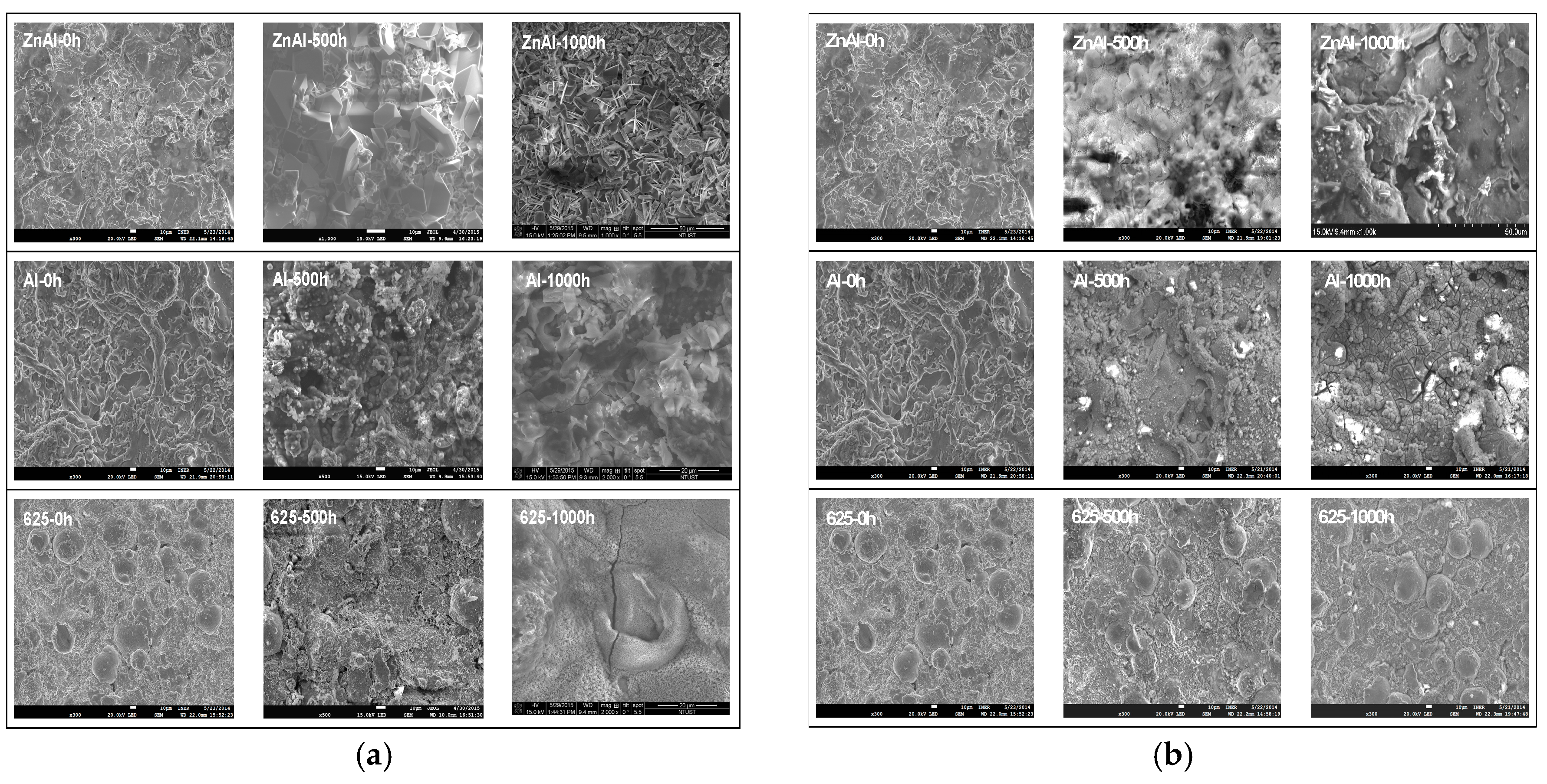
The microstructures of the thermal spray coatings before and after the corrosion tests with NaCl immersion and deposition were examined with SEM and are shown in Figure 3. The surface morphology indicates that the surface textures are strip-like and granular-like for the arc spray and HVOF, respectively. After the immersion corrosion, the surfaces of the ZnAl and Al coatings showed metal oxide and smoothed and flattened areas. However, the Inconel 625 coating showed increasingly less granular-like textures with the increase in immersion time, as shown in Figure 3.
For the NaCl deposition at 80 °C and 80% RH, the surfaces of the ZnAl coatings show an oxide crystal growth at 500 h and needle-snapped iron oxide crystals at 1000 h. The SEM-examined Al coating surfaces with corrosion show that the strip-like structures disappear and oxide crystals appear. The electron-charging effects were obvious in the SEM analysis with ZnAl and Al coating surfaces. The Inconel 625 coating surfaces show that the granular-like structures crumble, and cracks are found with needle-shaped crystals. With the EDS analysis, the needle-shaped oxide was identified to be iron-rich metal oxides. Both 1000 h immersion and deposition corrosion tests show needle-like oxides, which indicates that the coating layers penetrate with the chlorine-containing corrosion, as shown in Figure 4.
3.2. Crystalline Structures of the Thermal Spray Coatings
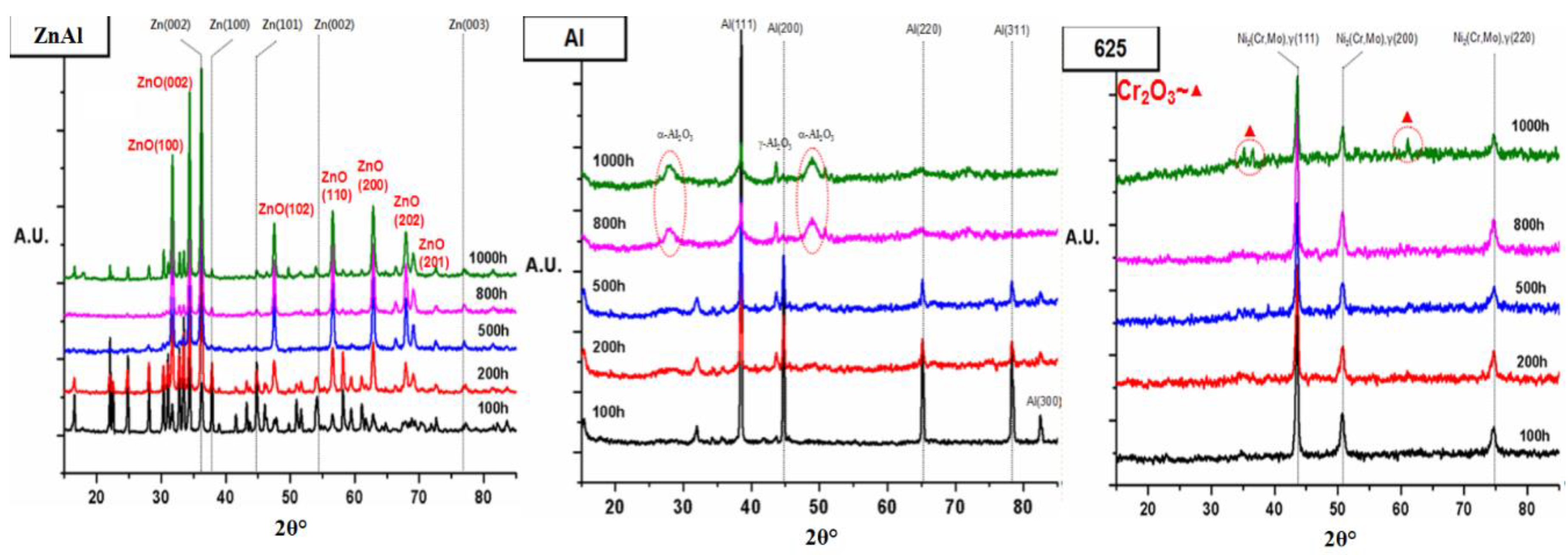
The crystalline structures of the thermal spray surfaces were revealed using XRD. Figure 5 shows the surfaces of three thermal coatings. The Inconel 625 alloy peaks are at 43.5°, 51.0°, and 74.8° for the Ni2(MnCr) facets (111), (200), and (220), respectively. The Al thermal coating layer has the Al metal crystalline phases at 38.1°, 44.7°, 65.3°, and 78.5° for the Al(111), Al(200), Al(220), and Al(311) facets, respectively. The ZnAl coating has Zn(001), Zn(101), Zn(002), Zn(103), Zn(110), and Zn(004) at 36.3°, 43.1°, 54.6°, 70.2°, 71.0°, and 78.2°, respectively. However, Zn(111) at 39.2° is shown in green in Figure 6, and the peak at 38.7° is attributed for the ZnAl alloy crystalline peak, which is shown on the inset of Figure 5. After the corrosion test, the surface produces the oxide layers.
Figure 6a shows the Inconel 625 layers during the corrosion tests at 0–1000 h. The Inconel 625 alloy coatings maintain the best crystalline among the three types. The Al coating experienced the long-term immersion corrosion test, as shown in Figure 6b. After the long-term corrosion in the 3.5 wt % aqueous NaCl, the crystal structures were notably different from the coating surfaces for ZnAl. The ZnAl coating layers indicate the complexity of the oxide phases, as shown in Figure 6c. The ZnO crystalline phases are found at 33.5° (002), 48.0° (102), 56.8° (110), 64.3° (200), 68.0° (202), and 72.3° (230). However, the Al2O3 crystalline is not clearly identified. Furthermore, many unfitted peaks are shown. Thus, there are more chemical reactions on the ZnAl coatings that we do not understand for the ZnAl thermal coating surface.
3.3. Surface Analysis of the Corrosion Specimens
Figure 2 presents the optical surface image of the coating specimens before and after 1000 h of corrosion. For the ZnAl coating, the surface of the specimen has an obvious change in color and becomes flattened compared to the as-sprayed specimen. The Al specimen surface has a rough morphology with white corrosion product. For the Inconel 625 coating, the surface appears unchanged regardless of the corrosion time.
The SEM images of three different types of coating surfaces are shown in Figure 3. All as-sprayed specimens present typical arc spray features, such as the laminar structure and pores on the surface. After 1000 h of corrosion, the surface of the ZnAl specimen was covered with a dense oxide layer, which uniformly formed on the surface and had few pores. The oxide layer was also found on the coating surface of the Al specimen. However, the oxide layer was discontinuous and had small cracks on the surface. The oxide layers of the ZnAl and Al specimens were confirmed by the following cross-sectional EDS analysis. The surface morphology of the Inconel 625 coating has localized pitting corrosion, which shows a small oxide with fine cracks.
3.4. Cross-Sectional Analysis of the Corrosion Specimens
EDS characterized the oxide layers of the corroded ZnAl and Al specimens, and the results are shown in Figure 7. For the ZnAl specimen (Figure 7a), the oxide layer was approximately 120 μm. Chromium was found to penetrate the coating layer to a depth of 140 μm. In contrast, the oxide layer of the Al specimen (Figure 7b) had an average thickness of 50 μm, was inhomogeneous and had fine cracks inside. The Al specimen showed a low chromium concentration in the coating layer, which is consistent with the low porosity level.
3.5. Electrochemical Analysis of the Corrosion Specimens
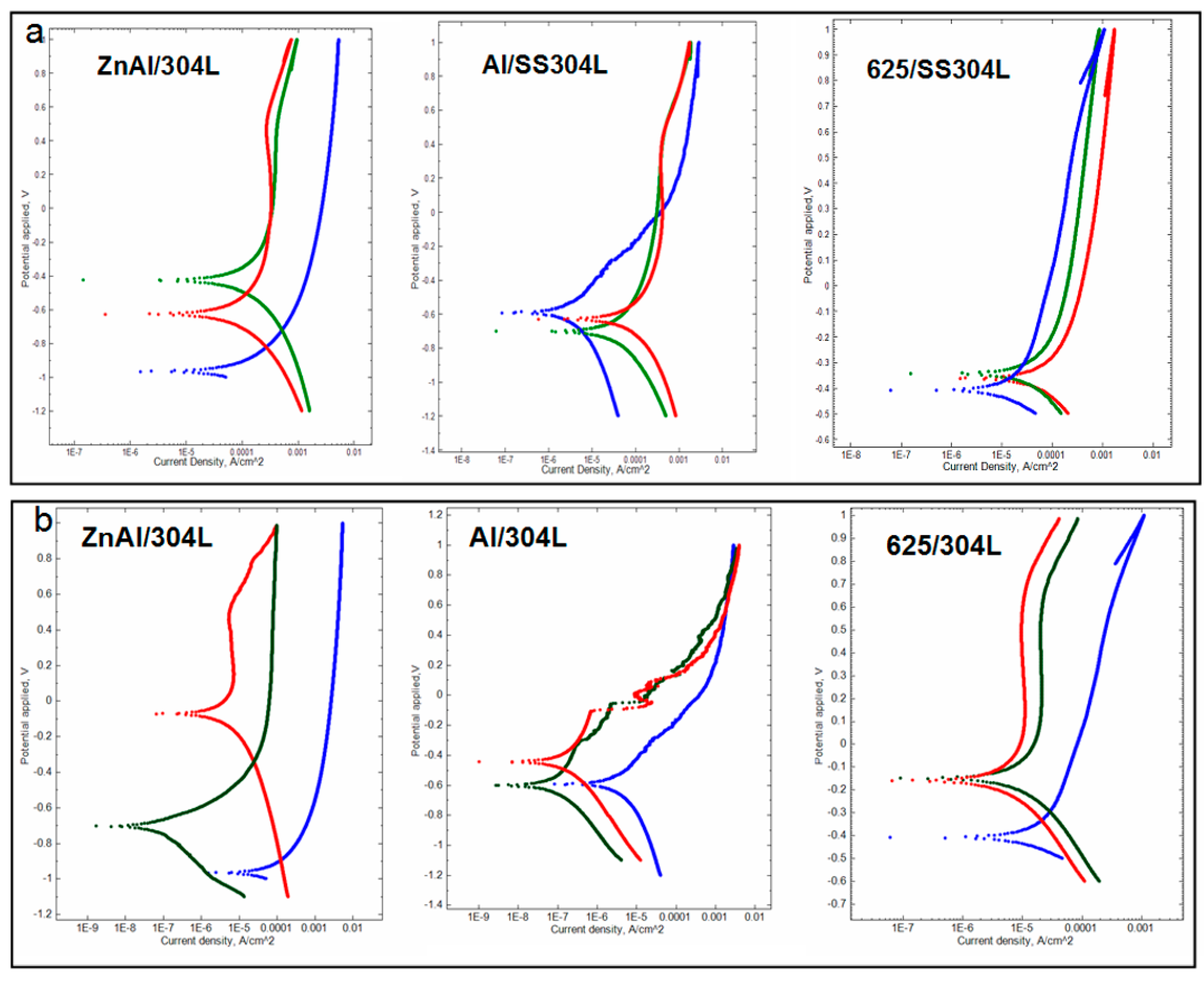
The electrochemical characteristics of various corrosion specimens are listed in Table 4. The linear cyclic voltammetry was measured with three coatings on SS304L for different corrosion times. The data were analyzed with the Tafel equation, and Tafel plots are shown in Figure 8. To understand the Tafel plot, we conducted two indications: the corrosion potential (Ecorr) and the corrosion current density (jcorr). Higher Ecorr and jcorr indicate higher corrosion, as shown in Table 4 and Table 5. The Al specimens have the lowest jcorr among the three thermal coating specimens in 3.5% aqueous NaCl. Thus, the Al coating has the lowest corrosion rate among the three thermal spray coatings in 3.5% aqueous NaCl. Nevertheless, the anti-corrosion mechanism of the Al coatings is an anodic protection layer on SS304L. The Ecorr values at 0, 500, and 1000 h are −0.59, −0.59, and −0.44 V, respectively. Thus, the Al layer corrodes to become the Al2O3 oxide phase during the corrosion test. After 100 h of the corrosion test, Al2O3 may produce an Al layer for protection. Furthermore, the Al2O3 layer becomes thicker with the increase in corrosion time, and Ecorr increases from −0.6 to −0.4 V. In reported literature, the Ecorr occurs at −0.6~−0.7 V. However, the Ecorr decreases to −0.7 V as the corrosion increases. The jcorr increases towards a higher current density with corrosion time increasing, as shown in Figure 8 [26,27,28,29].
The Inconel 625 thermal spray coating for the Tafel analysis shows the most positive Ecorr and jcorr among the three coatings. The Ecorr values are between −0.40 and −0.36 V. The Inconel 625 coating exhibits a stable surface for the 3.5 wt % NaCl corrosion. However, the Inconel 625 alloy has wider active surface areas than the Al coatings, according to the jcorr results. The results of 1000 h of the corrosion test showed that the jcorr of the Inconel 625 alloy and Al coating is 131.76 and 68.64 A/cm2, respectively.
In the Tafel analysis, the ZnAl coating shows the worst anti-corrosion performance among the three thermal coatings, according to the Ecorr and jcorr values. For electrochemical studies, the Al arc spray coating is the best choice against chlorine environment corrosion, and the ZnAl coating is the worst choice. However, the HVOF Inconel 625 alloy coating on SS304L has the best stability performance based on its Ecorr values, with notably small differences.
For the NaCl deposition corrosion under a controlled environment, the Ecorr of Inconel 625 is in the positive voltage, which means the Inconel 625 is the protection layer on the SS441. The degradation with increasing Fe dilution is the corrosion performance of the coatings. Corrosion resistance of the Inconel 625 coating is superior to the wrought 304 stainless steel. In addition, the Tafel analysis of Ecorr is about 0.2 V [24]. Tafel analysis of Ecorr values for Inconel 625 on the deposition corrosion are around −0.2 V too. After 1000 h corrosion, the coatings delaminate and the Ecorr decreases to −0.14 V. However, the jcorr decreases, as shown in Figure 8.
Comparing SS304L and the three thermal coatings, the Tafel analysis shows the following information: (1) SS304L has a more positive open-circuit potential (ocp) than the thermal coatings; (2) The Inconel 625 alloy coating has the most similar ocp to SS304L, and ZnAl has the most negative ocp to SS304L; (3) The parameter ba indicates the oxidization of the coating in the corrosion environments; (4) The parameter bc indicates the reduction of the coating in the corrosion environments; (5) Among the three coatings, only the Al thermal coating has a decreasing trend of oxidization in the two corrosion environments.
4. Conclusions
In 3.5 wt % aqueous NaCl to simulate seawater corrosion, zinc has a lower electrochemical potential than aluminum in the carbon steel substrate. In other words, zinc has a higher galvanic corrosion potential than aluminum, which leads to a higher degree of sacrificial zinc anodes. Although the ZnAl specimen presents the highest level of porosity, the corrosion product sealed the pores after the immersion test. Previous studies have shown that the corrosion product of the zinc coating in a 0.5 M NaCl solution is compact and consists of mainly zinc hydroxide, zinc oxide, and zinc hydroxide carbonate. The average hardness values of the corrosion layers of ZnAl and Al coating were 32.4 and 89.4 HV, respectively. The corrosion product of the Al specimens exhibits a hard/brittle structure and tends to peel off during the cleaning process. Compared to the Al coating, the corrosion product of the ZnAl specimen strongly adheres to the coating layers.
For 0.025 g/cm2 of NaCl deposition on the coating surface in a controlled environment, the Inconel 625 coating shows the lowest corrosion rate after 1000 h corrosion time at 0.1140 mm/year. After the 1000 h corrosion test, the corrosion rate of ZnAl and Al was found to be 0.8389 and 0.6504 mm/year, respectively.
On the coating surface after the corrosion test in both corrosion environments, Inconel 625 coatings show less delamination than the other coatings and the composition of surface oxides are simple in this study. This implies that Inconel 625 is suitable for anti-corrosion coatings in chlorine-containing environments. However, regarding costs, ZnAl costing may be the suitable candidate for this application.
Author Contributions
Conceptualization, T-Y.Y. and T.-Y.L.; Methodology, T.-C.C., K.-C.T. and W.-F.L.; Formal Analysis, T.-Y.Y. and T.-C.C.; Resources, J.-Y.H.; Data Curation, T.-Y.Y., T.-C.C. and T.-Y.L.; Writing–Original Draft Preparation, T.-Y.Y.; Writing–Review and Editing, T.-Y.L.; Supervision, J.-Y.H.
Funding
The research was partially funded by the Institute of Nuclear Energy Research (INER) and the Ministry of Science and Technology (MOST) of Taiwan (No. 103–3111–Y–042A–040).
Conflicts of Interest
The authors declare no conflict of interest.
References
- Kurc–Lisiecka, A.; Kalinowska–Ozgowicz, E. Structure and mechanical properties of austenitic steel after cold rolling. J. Achiev. Mater. Manuf. Eng. 2011, 44, 148–153. [Google Scholar]
- Sharifitabar, M.; Halvaee, A.; Khorshahian, S. Microstructure and mechanical properties of resistance upset butt welded 304 austenitic stainless steel joints. Mater. Des. 2011, 32, 3854–3864. [Google Scholar] [CrossRef]
- Wang, K.; Che, H.; Lei, M. Corrosion-fatigue properties of plasma-based low-energy nitrogen ion implanted AISI 304L austenitic stainless steel in borate buffer solution. Surf. Coat. Technol. 2016, 288, 30–35. [Google Scholar] [CrossRef]
- Drożdż, M.; Kyzio, K.; Grzesik, Z. Chromium-based oxidation-resistant coatings for the protection of engine valves in automotive vehicles. Mater. Technol. 2017, 51, 603–607. [Google Scholar] [CrossRef]
- Song, R.; Xiang, J.; Hou, D. Characteristic of mechanical properties and microstructure for 316L austenitic stainless steel. J. Iron Steel Res. Int. 2011, 18, 53–59. [Google Scholar] [CrossRef]
- Jafarzadegan, M.; Abdollah-Zadeh, A.; Feng, A.H.; Saeid, T.; Shen, J.; Assadi, H. Microstructure and mechanical properties of a dissimiliar friction stir weld between austenitic stainless steel and low carbon steel. J. Mater. Sci. Technol. 2013, 29, 367–372. [Google Scholar] [CrossRef]
- Ewing, R.C. Long-term storage of spent nuclear fuel. Nat. Mater. 2015, 14, 252–257. [Google Scholar] [CrossRef]
- Katayama, H.; Kuroda, S. Long-term atmospheric corrosion properties of thermally sprayed Zn, Al and Zn–Al coatings exposed in a coastal area. Corros. Sci. 2013, 76, 35–41. [Google Scholar] [CrossRef]
- Botsch, W.; Smalian, S.; Hinterding, P.; Völzke, H.; Wolff, D.; Kasparek, E.-M. Safety aspects of dry spent fuel storage and spent fuel management. In Proceedings of the ASEM 2013 15th International Conference on Environmental Remediation and Radioactive Waste Management, Brussels, Belgium, 8–12 September 2013. [Google Scholar]
- Einziger, R.E.; Tsai, H.C.; Billone, M.C.; Hilton, B.A. Examination of spent fuel rods after 15 years in dry storage. In Proceedings of the 10th International Conference on Nuclear Engineering, Arlington, VA, USA, 14–18 April 2002. [Google Scholar]
- NRC Information Notice 2012-20: Potential Chloride-Induced Stress Corrosion Cracking of Austenitic Stainless Steel and Maintenance of Dry Cask Storage System Canisters; NRC: Rockville, MD, USA, 2012.
- Tani, J.-I.; Mayuzumi, M.; Hara, N. Stress corrosion cracking of stainless-steel canister for concrete cask storage of spent fuel. J. Nucl. Mater. 2008, 379, 42–47. [Google Scholar] [CrossRef]
- Xiao, Y.; Jiang, X.; Xiao, Y.; Ma, L. Research on Zn–Al15 thermal spray metal coatings and its organic painting composite system protection performance. Procedia Eng. 2012, 27, 1644–1653. [Google Scholar] [CrossRef]
- Skerry, B.S.; Simpson, C.H. Corrosion and weathering of paints for atmospheric corrosion control. Corrosion 1993, 49, 663–674. [Google Scholar] [CrossRef]
- Zeng, R.; Li, X.; Liu, Z.; Zhang, F.; Li, S.; Cui, H. Corrosion resistance of Zn–Al layered double hydroxide/poly(lactic acid) composite coating on magnesium alloy AZ31. Front. Mater. Sci. 2015, 9, 355–365. [Google Scholar] [CrossRef]
- Marchebois, H.; Savall, C.; Bernard, J.; Touzain, S. Electrochemical behavior of zinc-rich powder coatings in artificial sea water. Electrochem. Acta 2004, 49, 2945–2954. [Google Scholar] [CrossRef]
- Pereira, D.; Scantlebury, J.D.; Ferreira, M.G.S.; Almeida, M.E. The application of electrochemical measurements to the study and behaviour of zinc-rich coatings. Corros. Sci. 1990, 30, 1135–1147. [Google Scholar] [CrossRef]
- Edrisy, A.; Perry, T.; Cheng, Y.T.; Alpas, A.T. Wear of thermal spray deposited low carbon steel coatings on aluminum alloys. Wear 2001, 251, 1023–1033. [Google Scholar] [CrossRef]
- Sokołowski, P.; Pawłowski, L.; Dietrich, D.; Lampke, T.; Jech, D. Advanced microscopic study of suspension plasma-sprayed zirconia coatings with different microstructures. J. Therm. Spray Technol. 2016, 25, 94–104. [Google Scholar] [CrossRef]
- Leonard, A. Review of External Stress Corrosion Cracking of 22%Cr Duplux Stainless Steel Phase 1—Operational Data Acquistion; Health & Safety Executive: Bootle, UK, 2003.
- Gedzevicius, I.; Valiulis, A.V. Influence of the particles velocity on the arc spraying coating adhesion. Mater. Sci. 2003, 9, 334–337. [Google Scholar]
- Steffens, H.-D.; Nassenstein, K. Influence of the spray velocity on arc-sprayed coating structures. J. Therm. Spray Technol. 1999, 8, 454–460. [Google Scholar] [CrossRef]
- Jandin, G.; Liao, H.; Feng, Z.Q.; Coddet, C. Correlations between operating conditions, microstructure and mechanical properties of twin wire arc sprayed steel coatings. Mater. Sci. Eng. A 2003, 349, 298–305. [Google Scholar] [CrossRef] [Green Version]
- Harvey, M.D.F.; Shrestha, S.; Sturgeon, A.J. Coatings for offshore applications by high velocity wire flame spraying. In Proceedings of the NACE 2005, Houston, TX, USA, 3–7 April 2005. [Google Scholar]
- ASTM C633-13(2017) Standard Test Method for Adhesion or Cohesion Strength of Thermal Spray Coatings; ASTM International: West Conshohocken, PA, USA, 2017.
- Carrasquero, E.J.; Lesage, J.; Puchi-Cabrera, E.S.; Staia, M.H. Fretting wear of HVOF Ni–Cr based alloy deposited on SAE 1045 steel. Surf. Coat. Technol. 2008, 202, 4544–4551. [Google Scholar] [CrossRef]
- Chen, T.-C.; Chou, C.-C.; Yung, T.-Y.; Tsai, K.-C.; Huang, J.-Y. Wear behavior of thermally sprayed Zn15Al, Al and Inconel 625 coatings on carbon steel. Surf. Technol. Sci. 2016, 303, 78–85. [Google Scholar]
- Lee, H.-S.; Singh, J.K.; Ismail, M.A.; Bhattacharya, C. Corrosion resistance properties of aluminum coating applied by arc thermal metal spray in SAE J2334 solution with exposure periods. Metals 2016, 6, 55. [Google Scholar] [CrossRef]
- Abioye, T.E.; Mccartney, D.G.; Clare, A.T. Laser cladding of Inconel 625 wire for corrosion protection. J. Mater. Process. Technol. 2015, 217, 232–240. [Google Scholar] [CrossRef] [Green Version]
Figure 1.
(a) Cross-section optical images of the three coatings, Al, ZnAl and Inconel 625 and (b) the cross-sectional hardness test for the three coatings on SS304L.
Figure 1.
(a) Cross-section optical images of the three coatings, Al, ZnAl and Inconel 625 and (b) the cross-sectional hardness test for the three coatings on SS304L.

Figure 2.
Surfaces after the corrosion test by (a) immersion in 3.5 wt % aqueous NaCl and (b) NaCl 0.025 g/cm2 deposition in a controlled environment.
Figure 2.
Surfaces after the corrosion test by (a) immersion in 3.5 wt % aqueous NaCl and (b) NaCl 0.025 g/cm2 deposition in a controlled environment.
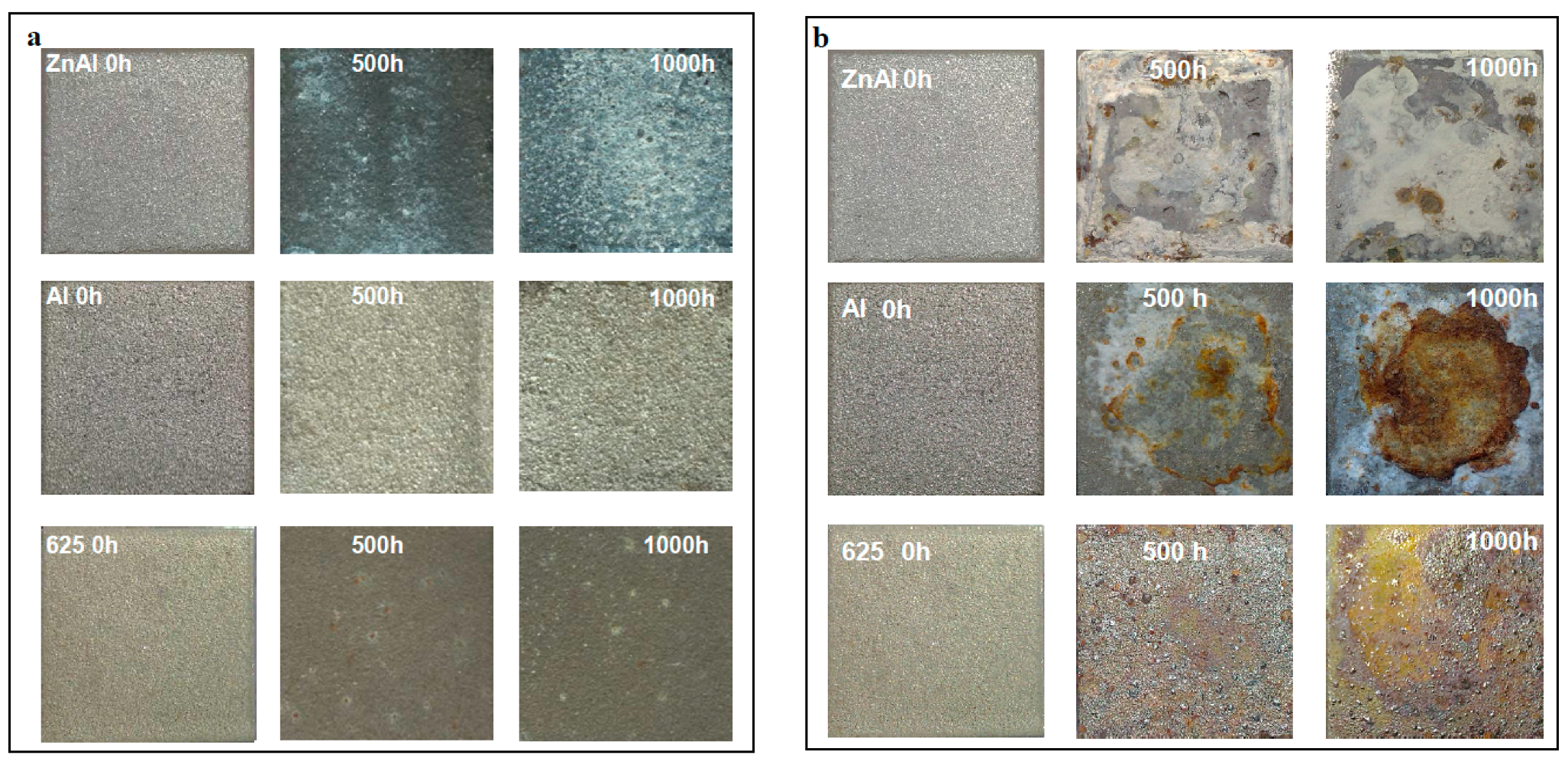
Figure 3.
Surface morphology of the thermal spray coatings after corrosion test: (a) the NaCl deposition in a controlled environmental corrosion test; and (b) the immersion corrosion test in 3.5 wt % NaCl solution (the scale bars indicate 10-μm).
Figure 3.
Surface morphology of the thermal spray coatings after corrosion test: (a) the NaCl deposition in a controlled environmental corrosion test; and (b) the immersion corrosion test in 3.5 wt % NaCl solution (the scale bars indicate 10-μm).

Figure 4.
Cross-sectional EDS image of the (a) ZnAl, (b) Al and (c) Inconel 625 coatings after 1000 h of immersion corrosion.
Figure 4.
Cross-sectional EDS image of the (a) ZnAl, (b) Al and (c) Inconel 625 coatings after 1000 h of immersion corrosion.
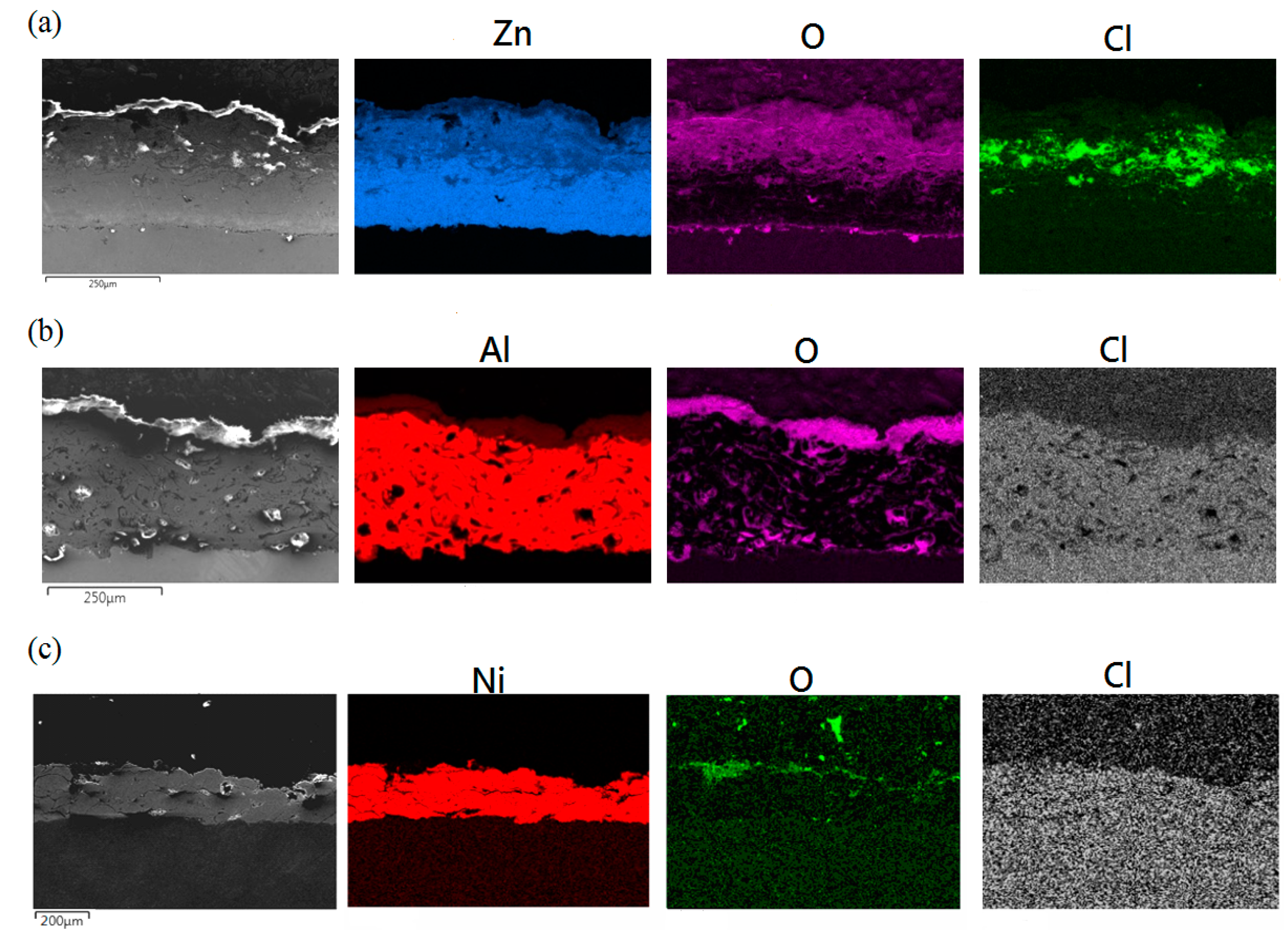
Figure 5.
XRD spectra of the crystalline phases of the Al–Arc, ZnAl–Arc, and Inconel 625 alloy coatings.
Figure 5.
XRD spectra of the crystalline phases of the Al–Arc, ZnAl–Arc, and Inconel 625 alloy coatings.
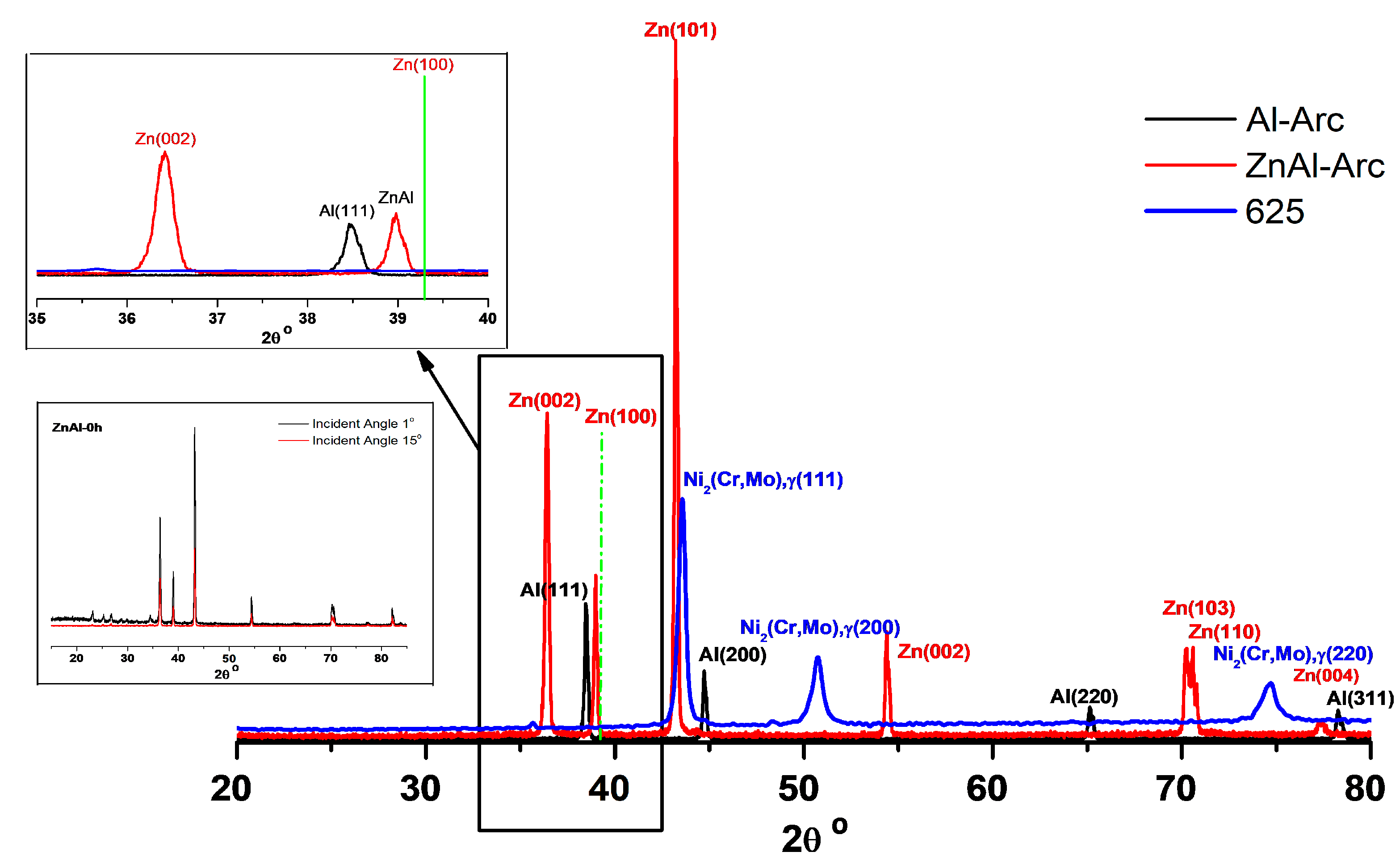
Figure 6.
XRD spectra of three thermal spray coatings after the 3.5 wt % NaCl immersion corrosion test: (a) Inconel 625 alloy; (b) Al; and (c) ZnAl at 0, 500, and 1000 h from left to right.
Figure 6.
XRD spectra of three thermal spray coatings after the 3.5 wt % NaCl immersion corrosion test: (a) Inconel 625 alloy; (b) Al; and (c) ZnAl at 0, 500, and 1000 h from left to right.
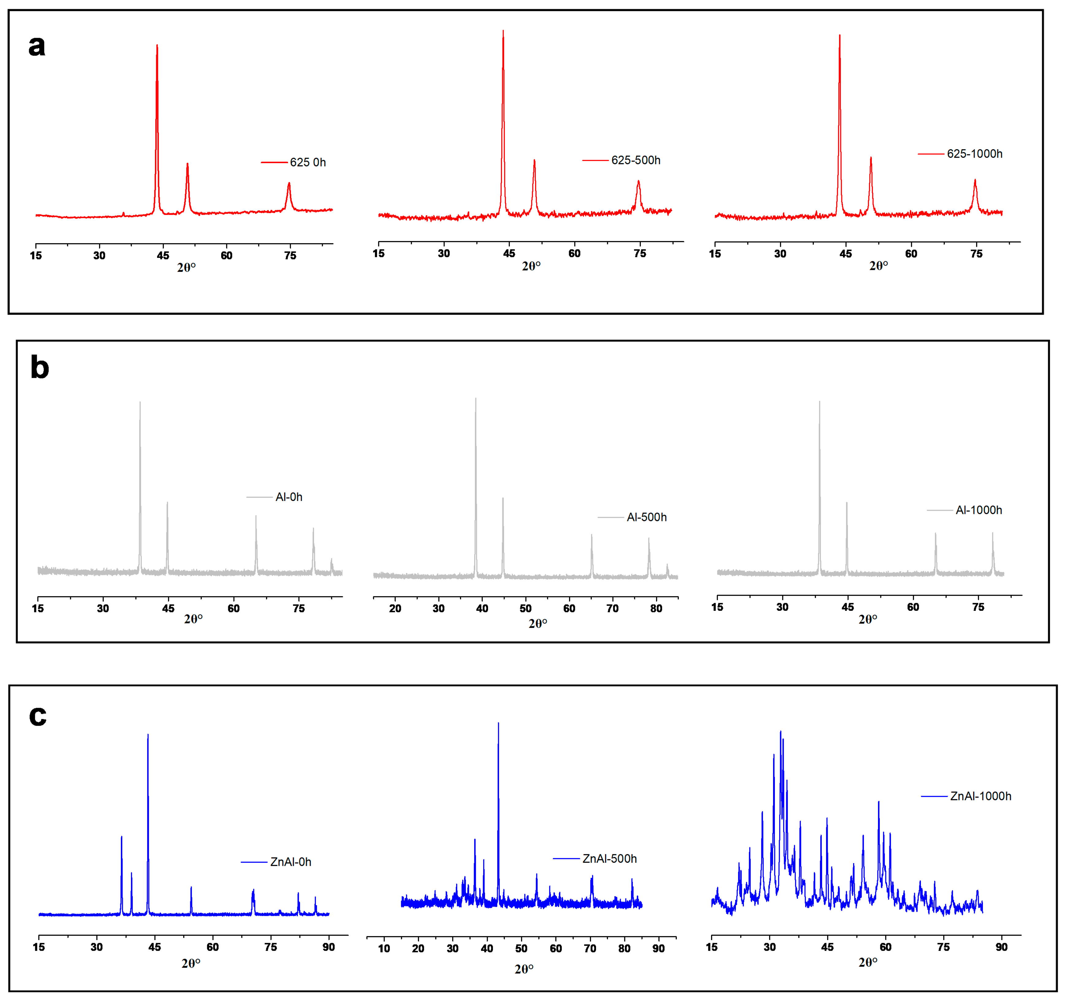
Figure 7.
XRD spectra of the thermal spray coatings with NaCl deposition and controlled environmental corrosion: (a) ZnAl; (b) Al; (c) Inconel 625 alloy.
Figure 7.
XRD spectra of the thermal spray coatings with NaCl deposition and controlled environmental corrosion: (a) ZnAl; (b) Al; (c) Inconel 625 alloy.

Figure 8.
Tafel plots for the thermal spray coatings after: (a) NaCl deposition with controlled environmental corrosion; and (b) the immersion corrosion test in 3.5 wt % aqueous NaCl solution. The blue, green, and red lines are for 0, 500, and 1000 h, respectively.
Figure 8.
Tafel plots for the thermal spray coatings after: (a) NaCl deposition with controlled environmental corrosion; and (b) the immersion corrosion test in 3.5 wt % aqueous NaCl solution. The blue, green, and red lines are for 0, 500, and 1000 h, respectively.

Table 1.
Chemical composition of the substrate and thermal spray materials. Unit: wt %.
| Coating | C | Si | Mn | Zn | Al | Co | Cr | Ni | Fe | Mo | Nb | P |
|---|---|---|---|---|---|---|---|---|---|---|---|---|
| Inconel 625 | – | – | – | – | – | 0.11 | 21.77 | 62.53 | 3.01 | 8.89 | 3.69 | – |
| Al | – | 0.04 | – | – | 99.79 | – | – | – | 0.17 | – | – | – |
| ZnAl | – | – | – | 85.09 | 14.89 | – | – | – | 0.02 | – | – | – |
| SS304L | 0.028 | 0.74 | 1.98 | – | 0.03 | – | 21.18 | 0.03 | 75.335 | – | 0.02 | 0.0045 |
Table 2.
Thermal spray parameters.
| Output Voltage | Current Density | Spray Distance | Deposit Rates | Feed Rate | Thickness |
| 31.0 V | 200 A | 150 mm | 98 g/min | 1 m/min | 200 μm |
| Fuel | Oxygen | Spray Distance | Deposit Rate | Feeder Speed | Thickness |
| 127 ± 10 psi | 138 ± 10 psi | 380 mm | 98 g/min | 375 rpm | 200 μm |
Table 3.
Adhesion test for the thermal spray coatings.
| Coating/Substrate | Binding Strength (MPa) |
|---|---|
| Inconel 625/304L | 36.4 ± 3.5 |
| ZnAl/304L | 11.0 ± 2.0 |
| Al/304L | 10.8 ± 1.5 |
Table 4.
Tafel analysis parameters for TSA in 3.5 wt % NaCl aqueous corrosion.
| Material | Corrosion Time (h) | Ecorr (V) | jcorr (A/cm2) | ba (V/dec) | bc (V/dec) | Corrosion Rate (mm/year) |
|---|---|---|---|---|---|---|
| SS304L | – | −0.3208 | 9.1244 | 0.7735 | 0.1292 | 0.1060 |
| ZnAl | 0 | −0.9624 | 13.194 | 0.0255 | 0.0731 | 0.1533 |
| 500 | −0.4237 | 154.94 | 0.2940 | 0.5989 | 1.6958 | |
| 1000 | −0.6234 | 92.839 | 0.3222 | 0.4952 | 1.0788 | |
| Al | 0 | −0.5888 | 1.4688 | 0.1539 | 0.2185 | 0.0171 |
| 500 | −0.598 | 12.966 | 0.0459 | 0.0626 | 0.0001 | |
| 1000 | −0.440 | 24.727 | 0.0612 | 0.0648 | 0.0002 | |
| Inconel 625 | 0 | −0.4051 | 15.448 | 0.1734 | 0.2739 | 0.1795 |
| 500 | −0.1465 | 0.5087 | 0.0247 | 0.0204 | 0.0059 | |
| 1000 | −0.1573 | 0.4447 | 0.0431 | 0.0169 | 0.0052 |
ba for anodic Tafel slope; bc for cathodic Tafel slope.
Table 5.
Tafel analysis parameters for the NaCl deposition corrosion.
| Material | Corrosion Time (h) | Ecorr (V) | jcorr (A/cm2) | ba (V/dec) | bc (V/dec) | Corrosion Rate (mm/year) |
|---|---|---|---|---|---|---|
| SS304L | – | −0.3208 | 9.1244 | 0.7735 | 0.1292 | 0.1060 |
| ZnAl | 0 | −0.7975 | 8.930 | 0.0255 | 0.0731 | 0.1038 |
| 500 | −0.4237 | 13.464 | 0.2940 | 0.5989 | 0.1564 | |
| 1000 | −0.6234 | 72.839 | 0.3222 | 0.4952 | 0.8389 | |
| Al1 | 0 | −0.4888 | 88.688 | 0.1539 | 0.2185 | 1.0296 |
| 500 | −0.3493 | 43.851 | 0.0993 | 0.2084 | 0.5095 | |
| 1000 | −0.3495 | 55.968 | 0.0455 | 0.6513 | 0.6504 | |
| Inconel 625 | 0 | −0.1963 | 22.225 | 0.1734 | 0.2739 | 0.2851 |
| 500 | −0.2051 | 10.881 | 0.3317 | 0.5076 | 0.1265 | |
| 1000 | −0.1475 | 9.810 | 0.4051 | 0.6067 | 0.1140 |
ba for anodic Tafel slope; bc for cathodic Tafel slope.
© 2019 by the authors. Licensee MDPI, Basel, Switzerland. This article is an open access article distributed under the terms and conditions of the Creative Commons Attribution (CC BY) license (http://creativecommons.org/licenses/by/4.0/).
Share and Cite
MDPI and ACS Style
Yung, T.-Y.; Chen, T.-C.; Tsai, K.-C.; Lu, W.-F.; Huang, J.-Y.; Liu, T.-Y. Thermal Spray Coatings of Al, ZnAl and Inconel 625 Alloys on SS304L for Anti-Saline Corrosion. Coatings 2019, 9, 32. https://doi.org/10.3390/coatings9010032
AMA Style
Yung T-Y, Chen T-C, Tsai K-C, Lu W-F, Huang J-Y, Liu T-Y. Thermal Spray Coatings of Al, ZnAl and Inconel 625 Alloys on SS304L for Anti-Saline Corrosion. Coatings. 2019; 9(1):32. https://doi.org/10.3390/coatings9010032
Chicago/Turabian StyleYung, Tung-Yuan, Tai-Cheng Chen, Kun-Cao Tsai, Wen-Feng Lu, Jiunn-Yuan Huang, and Ting-Yu Liu. 2019. "Thermal Spray Coatings of Al, ZnAl and Inconel 625 Alloys on SS304L for Anti-Saline Corrosion" Coatings 9, no. 1: 32. https://doi.org/10.3390/coatings9010032
Note that from the first issue of 2016, this journal uses article numbers instead of page numbers. See further details here.