Design of Highly Active Electrodes for Hydrogen Evolution Reaction Based on Mo-Rich Alloys Electrodeposited from Ammonium Acetate Bath


Abstract
:1. Introduction
2. Materials and Methods
2.1. Mo-Rich Alloys Electrodeposition
2.2. Morphological and Structural Study
2.3. Electrochemical Measurements
3. Results and Discussion
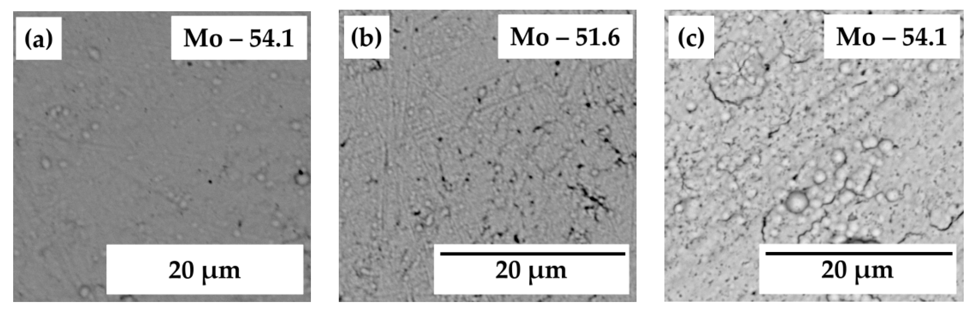
3.1. Design of Mo-Rich Alloys Coatings
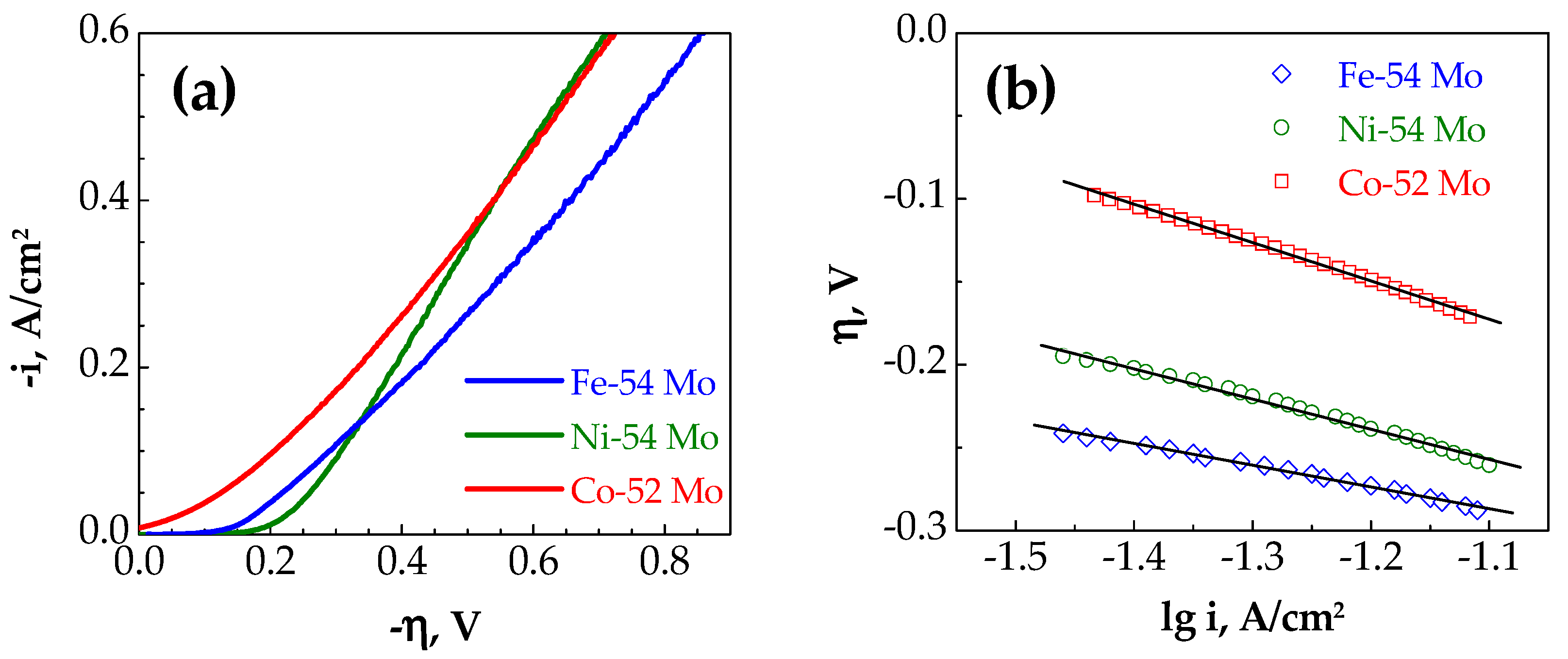
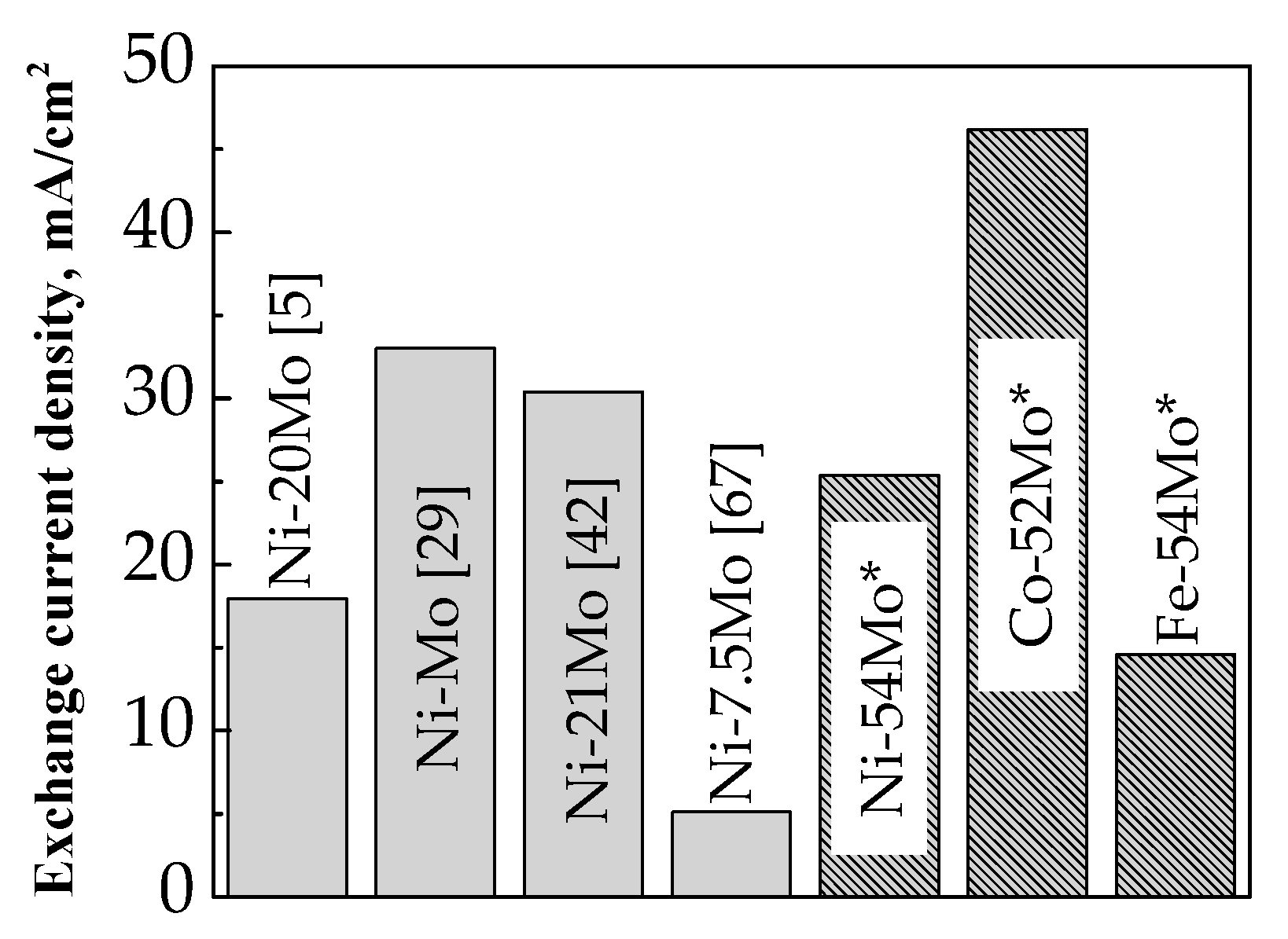
3.2. Catalytic Behavior
4. Conclusions
- The electrodeposition of Mo-rich (36–82 at.%) alloys with iron group metals (Ni, Co, Fe) from highly saturated ammonium acetate aqueous electrolytes is reported. The composition was affected by the [Ni(II)]/[Mo(VI)] ratio in the plating bath and cathodic current density.
- The electro-catalytic activity towards cathodic hydrogen evolution in 30 wt.% NaOH solution in the temperature range of 25–65 °C on the electrodeposited Ni–54 at.% Mo, Co–52 at.% Mo, Fe–54 at.% Mo and Co–52 at.% Mo alloy coatings characterized by amorphous-like structure has been investigated.
- Bimetallic Mo-based alloys are considered as more active for the HER in comparison with the cast Mo and Pt since they demonstrate higher apparent exchange current densities in the tested temperature range. The apparent exchange current density of hydrogen for Co–52 at.% Mo deposits were considerably higher than those for Ni–54 at.% Mo and Fe–54 at.% Mo alloy coatings and this can be attributed to the formation of stable intermetallic Co3Mo phase which ensures optimal Co and Mo distribution over the surface and produces larger active sites for the HER.
- The calculated activation energy values suggest that the Mo alloy coating with iron group metals shows promising electrocatalytic activity for the HER and among all investigated samples, the Co–52 at.% Mo electrode is characterized by a lower activation energy (27.9 kJ/mol) than the Ni–54 at.% Mo (32.5 kJ/mol) and Fe–54 at.% Mo (36.6 kJ/mol) coatings.
Author Contributions
Funding
Conflicts of Interest
References
- Studer, S.; Stucki, S.; Speight, J.D. Hydrogen as a Fuel. In Hydrogen as a Future Energy Carrier; Zttel, A., Borgschulte, A., Schlapbach, L., Eds.; Wiley-VCH Verlag GmbH & Co. KGaA: Weinheim, Germany, 2008; pp. 23–69. [Google Scholar]
- Sheng, W.; Gasteiger, H.A.; Shao-Horn, Y. Hydrogen oxidation and evolution reaction kinetics on platinum: Acid vs alkaline electrolytes. J. Electrochem. Soc. 2010, 157, B1529–B1536. [Google Scholar] [CrossRef]
- Halim, J.; Abdel-Karim, R.; El-Raghy, S.; Nabil, M.; Waheed, A. Electrodeposition and characterization of nanocrystalline Ni–Mo catalysts for hydrogen production. J. Nanomater. 2012, 2012, 845673. [Google Scholar] [CrossRef]
- Aaboubi, O. Hydrogen evolution activity of Ni–Mo coating electrodeposited under magnetic field control. Int. J. Hydrogen Energy 2011, 36, 4702–4709. [Google Scholar] [CrossRef]
- Raj, I.A.; Venkatesan, V.K. Characterization of nickel-molybdenum and nickel-molybdenum-iron alloy coatings as cathodes for alkaline water electrolysers. Int. J. Hydrogen Energy 1988, 13, 215–223. [Google Scholar]
- Kapoor, G.; Huang, Y.; Sarma, V.S.; Langdon, T.G.; Gubicza, J. Influence of Mo alloying on the thermal stability and hardness of ultrafine-grained Ni processed by high-pressure torsion. J. Mater. Res. Technol. 2017, 6, 361–368. [Google Scholar] [CrossRef]
- Feng, C.; Qian, W.; Liu, J.; Han, S.; Fu, N.; Ye, F.; Lin, H.; Jiang, J. Effect of ultrasonication on Ni–Mo coatings produced by DC electroformation. RSC Adv. 2016, 6, 30652–30660. [Google Scholar] [CrossRef]
- Laszczyńska, A.; Tylus, W.; Winiarski, J.; Szczygieł, I. Evolution of corrosion resistance and passive film properties of Ni–Mo alloy coatings during exposure to 0.5 M NaCl solution. Surf. Coat. Technol. 2017, 317, 26–37. [Google Scholar] [CrossRef]
- Chassaing, E.; Portail, N.; Levy, A.-F.; Wang, G. Characterisation of electrodeposited nanocrystalline Ni–Mo alloys. J. Appl. Electrochem. 2004, 34, 1085–1091. [Google Scholar] [CrossRef]
- Huang, P.-C.; Hou, K.-H.; Wang, G.-L.; Chen, M.-L.; Wang, J.-R. Corrosion resistance of the Ni–Mo alloy coatings related to coating’s electroplating parameters. Int. J. Electrochem. Sci. 2015, 10, 4972–4984. [Google Scholar]
- Jakšić, J.M.; Vojnović, M.V.; Krstajić, N.V. Kinetic analysis of hydrogen evolution at Ni–Mo alloy electrodes. Electrochim. Acta 2000, 45, 4151–4158. [Google Scholar] [CrossRef]
- Xu, C.; Zhou, J.; Zeng, M.; Fu, X.; Liu, X.; Li, J. Electrodeposition mechanism and characterization of Ni–Mo alloy and its electrocatalytic performance for hydrogen evolution. Int. J. Hydrogen Energy 2016, 41, 13341–13349. [Google Scholar] [CrossRef]
- Mech, K.; Zabinski, P.; Mucha, M.; Kowalik, R. Electrodeposition of catalytically active Ni–Mo alloys/elektroosadzanie aktywnych katalitycznie stopów Ni–Mo. Arch. Metall. Mater. 2013, 58, 227–229. [Google Scholar] [CrossRef]
- Jeremiasse, A.W.; Bergsma, J.; Kleijn, J.M.; Saakes, M.; Buisman, C.J.N.; Cohen Stuart, M.; Hamelers, H.V.M. Performance of metal alloys as hydrogen evolution reaction catalysts in a microbial electrolysis cell. Int. J. Hydrogen Energy 2011, 36, 10482–10489. [Google Scholar] [CrossRef]
- Navarro-Flores, E.; Chong, Z.; Omanovic, S. Characterization of Ni, NiMo, NiW and NiFe electroactive coatings as electrocatalysts for hydrogen evolution in an acidic medium. J. Mol. Catal. A Chem. 2005, 226, 179–197. [Google Scholar] [CrossRef]
- Manazoğlu, M.; Hapçı, G.; Orhan, G. Electrochemical deposition and characterization of Ni–Mo alloys as cathode for alkaline water electrolysis. J. Mater. Eng. Perform. 2016, 25, 130–137. [Google Scholar] [CrossRef]
- Martinez, S.; Metikoš-Huković, M.; Valek, L. Electrocatalytic properties of electrodeposited Ni–15Mo cathodes for the HER in acid solutions: Synergistic electronic effect. J. Mol. Catal. A Chem. 2006, 245, 114–121. [Google Scholar] [CrossRef]
- Lu, G.; Evans, P.; Zangari, G. Electrocatalytic properties of Ni-based alloys toward hydrogen evolution reaction in acid media. J. Electrochem. Soc. 2003, 150, A551–A557. [Google Scholar] [CrossRef]
- Huang, L.; Yang, F.; Xu, S.; Zhou, S. Studies of structure and electrocatalytic hydrogen evolution on electrodeposited nanocrystalline Ni–Mo alloy electrodes. Trans. IMF 2001, 79, 136–139. [Google Scholar] [CrossRef]
- Kedzierzawski, P.; Oleszak, D.; Janik-Czachor, M. Hydrogen evolution on hot and cold consolidated Ni–Mo alloys produced by mechanical alloying. Mater. Sci. Eng. A 2001, 300, 105–112. [Google Scholar] [CrossRef]
- González, G.; Sagarzazu, A.; Villalba, R.; Ochoa, J. Comparative study of NiW, NiMo and MoW prepared by mechanical alloying. J. Alloys Compd. 2007, 434–435, 525–529. [Google Scholar] [CrossRef]
- Schulz, R.; Huot, J.Y.; Trudeau, M.L.; Dignard-Bailey, L.; Yan, Z.H.; Jin, S.; Lamarre, A.; Ghali, E.; Van Neste, A. Nanocrystalline Ni–Mo alloys and their application in electrocatalysis. J. Mater. Res. 1994, 9, 2998–3008. [Google Scholar] [CrossRef]
- Yang, C.; Muránsky, O.; Zhu, H.; Thorogood, G.J.; Huang, H.; Zhou, X. On the origin of strengthening mechanisms in Ni–Mo alloys prepared via powder metallurgy. Mater. Des. 2017, 113, 223–231. [Google Scholar] [CrossRef]
- Bhattacharjee, P.P.; Ray, R.K.; Upadhyaya, A. Development of cube texture in pure Ni, Ni–W and Ni–Mo alloys prepared by the powder metallurgy route. Scripta Materialia 2005, 53, 1477–1481. [Google Scholar] [CrossRef]
- Tang, X.; Xiao, L.; Yang, C.; Lu, J.; Zhuang, L. Noble fabrication of Ni–Mo cathode for alkaline water electrolysis and alkaline polymer electrolyte water electrolysis. Int. J. Hydrogen Energy 2014, 39, 3055–3060. [Google Scholar] [CrossRef]
- Li, X.; Liu, Z.; Wang, Y. Microstructure and corrosion properties of laser cladding MoNi based alloy coatings. Sci. China Technol. Sci. 2014, 57, 980–989. [Google Scholar] [CrossRef]
- Aaboubi, O.; Chopart, J.-P. Magnetic field effect on molybdenum based alloys electrodeposition. ECS Trans. 2010, 25, 27–34. [Google Scholar]
- Mikolajczyk, T.; Pierozynski, B. Influence of electrodeposited Ni–Mo alloy on hydrogen evolution reaction at nickel foam cathode. Int. J. Electrochem. Sc. 2018, 13, 621–630. [Google Scholar] [CrossRef]
- González-Buch, C.; Herraiz-Cardona, I.; Ortega, E.M.; García-Antón, J.; Pérez-Herranz, V. Development of Ni–Mo, Ni–W and Ni–Co macroporous materials for hydrogen evolution reaction. Chem. Eng. Trans. 2013, 32, 865–870. [Google Scholar]
- Krstajic, N.V.; Jovic, V.D.; Gajic-krstajic, L.; Jovic, B.M.; Antozzi, A.L.; Martelli, G.N. Electrodeposition of Ni–Mo alloy coatings and their characterization as cathodes for hydrogen evolution in sodium hydroxide solution. Int. J. Hydrogen Energy 2008, 33, 3676–3687. [Google Scholar] [CrossRef]
- Donten, M.; Cesiulis, H.; Stojek, Z. Electrodeposition of amorphous/nanocrystalline and polycrystalline Ni–Mo alloys from pyrophosphate baths. Electrochim. Acta 2005, 50, 1405–1412. [Google Scholar] [CrossRef]
- Gennero de Chialvo, M.R.; Chialvo, A.C. Hydrogen evolution reaction on smooth Ni(1−x) + Mo(x) alloys (0 ≤ x ≤ 0.25). J. Electroanal. Chem. 1998, 448, 87–93. [Google Scholar] [CrossRef]
- Kuznetsov, V.V.; Kalinkina, A.A.; Pshenichkina, T.V.; Balabaev, V.V. Electrocatalytic properties of cobalt-molybdenum alloy deposits in the hydrogen evolution reaction. Russ. J. Electrochem. 2008, 44, 1350–1358. [Google Scholar] [CrossRef]
- Podlaha, E.J.; Landolt, D. Induced codeposition: 1. An experimental investigation of Ni–Mo alloys. J. Electrochem. Soc. 1996, 143, 885–892. [Google Scholar] [CrossRef]
- Bigos, A.; Beltowska-Lehman, E.; Kot, M. Studies on electrochemical deposition and physicochemical properties of nanocrystalline Ni–Mo alloys. Surf. Coat. Technol. 2017, 317, 103–109. [Google Scholar] [CrossRef]
- Casciano, P.N.S.; Benevides, R.L.; Santana, R.A.C.; Correia, A.N.; de Lima-Neto, P. Factorial design in the electrodeposition of Co–Mo coatings and their evaluations for hydrogen evolution reaction. J. Alloys Compd. 2017, 723, 164–171. [Google Scholar] [CrossRef]
- Allahyarzadeh, M.H.; Roozbehani, B.; Ashrafi, A.; Shadizadeh, S.R.; Kheradmand, E. Electrochemically deposition of high Mo content amorphous/nanocrystalline Ni–Mo using ionic liquids as additive. ECS Trans. 2012, 41, 11–28. [Google Scholar]
- Elezović, N.; Grgur, N.B.; Krstajić, N.V.; Jović, V.D. Electrodeposition and characterization of Fe–Mo alloys as cathodes for hydrogen evolution in the process of chlorate production. J. Serb. Chem. Soc. 2005, 70, 879–889. [Google Scholar]
- Elezović, N.R.; Jović, V.D.; Krstajić, N.V. Kinetics of the hydrogen evolution reaction on Fe–Mo film deposited on mild steel support in alkaline solution. Electrochim. Acta 2005, 50, 5594–5601. [Google Scholar] [CrossRef]
- Barbano, E.P.; de Carvalho, M.F.; Carlos, I.A. Electrodeposition and characterization of binary Fe–Mo alloys from trisodium nitrilotriacetate bath. J. Electroanal. Chem. 2016, 775, 146–156. [Google Scholar] [CrossRef]
- Niedbała, J. Production of Ni − Mo + Mo composite coatings with increased content of embeded Mo. Arch. Mater. Sci. 2006, 27, 121–127. [Google Scholar]
- Han, Q.; Cui, S.; Pu, N.; Chen, J.; Liu, K.; Wei, X. A study on pulse plating amorphous Ni–Mo alloy coating used as HER cathode in alkaline medium. Int. J. Hydrogen Energy 2010, 35, 5194–5201. [Google Scholar] [CrossRef]
- Sun, S.; Podlaha, E.J. Electrodeposition of Mo-Rich, MoNi alloys from an aqueous electrolyte. J. Electrochem. Soc. 2012, 159, D97–D102. [Google Scholar] [CrossRef]
- Morley, T.J.; Penner, L.; Schaffer, P.; Ruth, T.J.; Bénard, F.; Asselin, E. The deposition of smooth metallic molybdenum from aqueous electrolytes containing molybdate ions. Electrochem. Commun. 2012, 15, 78–80. [Google Scholar] [CrossRef]
- Kahlert, H. Reference electrodes. In Electroanalytical Methods, 2nd ed.; Scholz, F., Ed.; Springer: Berlin/Heidelberg, Germany, 2010; pp. 291–308. [Google Scholar]
- Fosdick, S.E.; Berglund, S.P.; Mullins, C.B.; Crooks, R.M. Evaluating electrocatalysts for the hydrogen evolution reaction using bipolar electrode arrays: Bi- and trimetallic combinations of Co, Fe, Ni, Mo, and W. ACS Catal. 2014, 4, 1332–1339. [Google Scholar] [CrossRef]
- Raj, I.A.; Vasu, K.I. Transition metal-based hydrogen electrodes in alkaline solution? electrocatalysis on nickel based binary alloy coatings. J. Appl. Electrochem. 1990, 20, 32–38. [Google Scholar] [CrossRef]
- Sanches, L.S.; Domingues, S.H.; Marino, C.E.B.; Mascaro, L.H. Characterisation of electrochemically deposited Ni–Mo alloy coatings. Electrochem. Commun. 2004, 6, 543–548. [Google Scholar] [CrossRef]
- Rodríguez-Valdez, L.; Estrada-Guel, I.; Almeraya-Calderon, F.; Neri-Flores, M.A.; Martinez-Villafane, A.; Martinez-Sanchez, R. Electrochemical performance of hydrogen evolution reaction of Ni–Mo electrodes obtained by mechanical alloying. Int. J. Hydrogen Energy 2004, 29, 1141–1145. [Google Scholar] [CrossRef]
- Beltowska-Lehman, E. Kinetics of induced electrodeposition of alloys containing Mo from citrate solutions. Phys. Status Solidi C 2008, 5, 3514–3517. [Google Scholar] [CrossRef]
- Benaicha, M.; Allam, M.; Dakhouche, A.; Hamla, M. Electrodeposition and characterization of W-rich NiW alloys from citrate electrolyte. Int. J. Electrochem. Sci. 2016, 11, 7605–7620. [Google Scholar] [CrossRef]
- Bigos, A.; Bełtowska-Lehman, E.; Kania, B.; Szczerba, M. Ni–Mo alloys electrodeposited under direct current from citrate-ammonia plating bath. Inżynieria Materiałowa. 2013, 34, 135–139. [Google Scholar]
- Costovici, S.; Manea, A.-C.; Visan, T.; Anicai, L. Investigation of Ni–Mo and Co–Mo alloys electrodeposition involving choline chloride based ionic liquids. Electrochim. Acta 2016, 207, 97–111. [Google Scholar] [CrossRef]
- Karolus, M.; Łągiewka, E. Crystallite size and lattice strain in nanocrystalline Ni–Mo alloys studied by Rietveld refinement. J. Alloys Compd. 2004, 367, 235–238. [Google Scholar] [CrossRef]
- Kuznetsov, V.V.; Golyanin, K.E.; Ladygina, Y.S.; Pshenichkina, T.V.; Lyakhov, B.F.; Pokholok, K.V. Electrodeposition of iron–molybdenum alloy from ammonium–citrate solutions and properties of produced materials. Russ. J. Electrochem. 2015, 51, 748–757. [Google Scholar] [CrossRef]
- Nicolenco, A.; Tsyntsaru, N.; Fornell, J.; Pellicer, E.; Reklaitis, J.; Baltrunas, D.; Cesiulis, H.; Sort, J. Mapping of magnetic and mechanical properties of Fe-W alloys electrodeposited from Fe(III)-based glycolate-citrate bath. Mater. Des. 2018, 139, 429–438. [Google Scholar] [CrossRef]
- Kinh, V.Q.; Chassaing, E.; Saurat, M. Electroplating of crack-free corrosion resistant Co–Mo alloy coatings. Electrodepos. Surf. Treat. 1975, 3, 205–212. [Google Scholar] [CrossRef]
- Jakšić, M.M. Advances in electrocatalysis for hydrogen evolution in the light of the Brewer-Engel valence-bond theory. J. Mol. Catal. 1986, 38, 161–202. [Google Scholar] [CrossRef]
- Zhou, Q.F.; Lu, L.Y.; Yu, L.N.; Xu, X.G.; Jiang, Y. Multifunctional Co–Mo films fabricated by electrochemical deposition. Electrochim. Acta 2013, 106, 258–263. [Google Scholar] [CrossRef]
- Lee, C.R.; Kang, S.G. Electrochemical stability of Co–Mo intermetallic compound electrodes for hydrogen oxidation reaction in hot KOH solution. J. Power Sources 2000, 87, 64–68. [Google Scholar] [CrossRef]
- Conway, B.E.; Tessier, D.F.; Wilkinson, D.P. Temperature dependence of the Tafel slope and electrochemical barrier symmetry factor. J. Electrochem. Soc. 1989, 136, 2486–2493. [Google Scholar] [CrossRef]
- Fan, C.; Piron, D.L.; Sleb, A.; Paradis, P. Study of electrodeposited nickel-molybdenum, nickel-tungsten, cobalt-molybdenum, and cobalt-tungsten as hydrogen electrodes in alkaline water electrolysis. J. Electrochem. Soc. 1994, 141, 382–387. [Google Scholar] [CrossRef]
- Lupu, D.; Mǎrginean, P.; Biriş, A.R. Hydrogen in some synergetic electrocatalysts. J. Alloys Compd. 1996, 245, 146–152. [Google Scholar] [CrossRef]
- Domínguez-Crespo, M.A.; Plata-Torres, M.; Torres-Huerta, A.M.; Arce-Estrada, E.M.; Hallen-López, J.M. Kinetic study of hydrogen evolution reaction on Ni30 Mo70, Co30Mo70, Co30Ni70 and Co10Ni20Mo70 alloy electrodes. Mater. Charact. 2005, 55, 83–91. [Google Scholar] [CrossRef]
- Manazoğlu, M.; Hapçı, G.; Orhan, G. Effect of electrolysis parameters of Ni–Mo alloy on the electrocatalytic activity for hydrogen evaluation and their stability in alkali medium. J. Appl. Electrochem. 2016, 46, 191–204. [Google Scholar] [CrossRef]
- Shetty, S.; Mohamed Jaffer Sadiq, M.; Bhat, D.K.; Hegde, A.C. Electrodeposition and characterization of Ni–Mo alloy as an electrocatalyst for alkaline water electrolysis. J. Electroanal. Chem. 2017, 796, 57–65. [Google Scholar] [CrossRef]
- Tasic, G.S.; Maslovara, S.P.; Zugic, D.L.; Maksic, A.D.; Marceta Kaninski, M.P. Characterization of the Ni–Mo catalyst formed in situ during hydrogen generation from alkaline water electrolysis. Int. J. Hydrogen Energy 2011, 36, 11588–11595. [Google Scholar] [CrossRef]
- Panek, J.; Budniok, A. Ni + Mo composite coatings for hydrogen evolution reaction. Surf. Interface Anal. 2008, 40, 237–241. [Google Scholar] [CrossRef] [Green Version]
- Shetty, S.; Sadiq, M.M.J.; Bhat, D.K.; Hegde, A.C. Electrodeposition of Ni–Mo–rGO composite electrodes for efficient hydrogen production in an alkaline medium. New J. Chem. 2018, 42, 4661–4669. [Google Scholar] [CrossRef]
- Kublanovsky, V.S.; Yapontseva, Y.S. Electrocatalytic properties of Co–Mo alloys electrodeposited from a citrate-pyrophosphate electrolyte. Electrocatalysis 2014, 5, 372–378. [Google Scholar] [CrossRef]
- Subramania, A.; Sathiyapriya, A.; Muralidharan, V. Electrocatalytic cobalt–molybdenum alloy deposits. Int. J. Hydrogen Energy 2007, 32, 2843–2847. [Google Scholar] [CrossRef]


| Bath | CH3CO2K | CH3CO2NH4 | (NH4)2MoO4 | NiSO4∙7H2O | CoSO4∙7H2O | FeSO4∙7H2O | pH |
|---|---|---|---|---|---|---|---|
| 1 | 10.2 M | 10.4 M | 0.004 M | 0.001 M | – | – | 8.2 |
| 2 | 0.002 M | ||||||
| 3 | 0.004 M | ||||||
| 4 | – | 0.002 M | 8.3 | ||||
| 5 | – | 0.002 M |
| [Ni(II)]: [Mo(VI)] Ratio | Applied Cathodic j, 30 mA/cm2 | Applied Cathodic j, 100 mA/cm2 | ||
|---|---|---|---|---|
| SEM | Partial Cathodic j, mA/cm2 | SEM | Partial Cathodic j, mA/cm2 | |
| 1 | 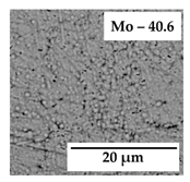 | jNi = 0.6 |  | jNi = 1.3 |
| jMo = 1.3 | jMo = 2.2 | |||
| jH₂ = 28.1 | jH₂ = 96.5 | |||
| 0.5 | 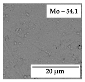 | jNi = 0.3 | 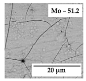 | jNi = 0.6 |
| jMo = 1.2 | jMo = 2.1 | |||
| jH₂ = 28.5 | jH₂ = 97.3 | |||
| 0.25 | 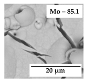 | jNi = 0.02 |  | jNi = 0.2 |
| jMo = 0.27 | jMo = 2.3 | |||
| jH₂ = 29.71 | jH₂ = 97.5 | |||
| Parameter | Electrode | ||||
|---|---|---|---|---|---|
| Ni–54 Mo | Co–52 Mo | Fe–54 Mo | Mo | Pt | |
| io (mA/cm2) | 0.62 | 1.90 | 0.23 | 2.90 × 10⁻⁵ | 2.63 |
| bc (mV/dec) | 128 | 132 | 152 | 231 | 122 |
| ηi (V) | 0.46 | 0.43 | 0.54 | 0.67 | 0.48 |
| iη (A/cm2) | 9.1 × 10⁻² | 1.8 × 10⁻¹ | 9.3 × 10⁻² | 5.4 × 10⁻⁴ | 8.2 × 10⁻² |
| Sample | Measurement temperature (°C) | |||||||||
|---|---|---|---|---|---|---|---|---|---|---|
| 25 | 35 | 45 | 55 | 65 | ||||||
| i0 | bc | i0 | bc | i0 | bc | i0 | bc | i0 | bc | |
| Ni–54 Mo | 0.62 | 128 | 3.21 | 128 | 7.32 | 119 | 1.47 | 116 | 25.4 | 123 |
| Fe–54 Mo | 0.23 | 152 | 0.99 | 148 | 4.33 | 142 | 5.83 | 139 | 14.6 | 145 |
| Co–52 Mo | 1.90 | 132 | 9.53 | 130 | 17.1 | 128 | 32.0 | 121 | 46.2 | 119 |
| Mo | 2.9∙× 10−2 | 231 | 8.3∙× 10−2 | 220 | 1.9∙× 10−1 | 220 | 2.1∙× 10−1 | 215 | 2.3∙× 10−1 | 221 |
| Pt | 2.63 | 122 | 3.68 | 129 | 6.51 | 120 | 2.63 | 125 | 11.5 | 125 |
| Sample | Mo content (at.%) | Media | i0 (mA/cm2) | Reference |
|---|---|---|---|---|
| Ni–Mo | 26 | 8.25 M NaOH, 85 °C | 44.4 | [4] |
| 20 | 6 M KOH; 80 °C | 18.62 | [5] | |
| 33.8 | 7 M KOH, 25 °C | 2.8 | [19] | |
| – | 7 M KOH, 80 °C | 55.24 | [29] | |
| 25 | 2 M NaOH, 30 °C | 3.1 × 10⁻² | [32] | |
| 20.8 | 11 M NaOH; 80 °C | 42.4 | [42] | |
| 29.8 | 1 M NaOH, 30 °C | 11.1 | [65] | |
| 27.5 | 1 M KOH | 3.18 × 10⁻³ | [66] | |
| 7.5 | 6 M KOH; 70 °C | 7.3 | [67] | |
| NiMo-modified Ni foam | 2.5 | 0.1 M NaOH, 25 °C | 4.1 × 10⁻² | [28] |
| Ni + Mo composite | 44 | 5 M KOH; 25 °C | 1.0 | [68] |
| Ni–Mo–rGO | 30.8 | 1 M KOH; 25 °C | 4.31 × 10⁻³ | [69] |
| Ni–Mo | 10.4 | 7 M KOH, 25 °C | 2.6 × 10⁻² | [62] |
| Co–Mo | 21.4 | 2.3 × 10⁻² | ||
| Co–Mo | 40.9 | 1 M NaOH | 1.5 | [33] |
| 32 | 0.5 M NaOH; 60 °C | 6.9 × 10⁻³ | [36] | |
| 25 | 1 M NaOH, 25 °C | 0.13 | [59] | |
| 19 | 1 M KOH, 25 °C | 0.36 | [70] | |
| 33 | 1 M NaOH, 30 °C | 5.0 × 10⁻² | [71] | |
| Fe–Mo | 59.3 | 1 M NaOH, 25 °C | 2.4 × 10⁻³ | [39] |
© 2019 by the authors. Licensee MDPI, Basel, Switzerland. This article is an open access article distributed under the terms and conditions of the Creative Commons Attribution (CC BY) license (http://creativecommons.org/licenses/by/4.0/).
Share and Cite
Vernickaitė, E.; Bersirova, O.; Cesiulis, H.; Tsyntsaru, N. Design of Highly Active Electrodes for Hydrogen Evolution Reaction Based on Mo-Rich Alloys Electrodeposited from Ammonium Acetate Bath. Coatings 2019, 9, 85. https://doi.org/10.3390/coatings9020085
Vernickaitė E, Bersirova O, Cesiulis H, Tsyntsaru N. Design of Highly Active Electrodes for Hydrogen Evolution Reaction Based on Mo-Rich Alloys Electrodeposited from Ammonium Acetate Bath. Coatings. 2019; 9(2):85. https://doi.org/10.3390/coatings9020085
Chicago/Turabian StyleVernickaitė, Edita, Oksana Bersirova, Henrikas Cesiulis, and Natalia Tsyntsaru. 2019. "Design of Highly Active Electrodes for Hydrogen Evolution Reaction Based on Mo-Rich Alloys Electrodeposited from Ammonium Acetate Bath" Coatings 9, no. 2: 85. https://doi.org/10.3390/coatings9020085