Aluminum Coated Micro Glass Spheres to Increase the Infrared Reflectance
by
Laura Schwinger
1,*, 
Sebastian Lehmann
1,
Lukas Zielbauer
1,
Benedikt Scharfe
2 and
Thorsten Gerdes
1 1
Ceramic Materials Engineering-Keylab Glastechnology, University of Bayreuth, 95440 Bayreuth, Germany
2
Deggendorf Institute of Technology, TAZ Spiegelau, 94518 Spiegelau, Germany
*
Author to whom correspondence should be addressed.
Coatings 2019, 9(3), 187; https://doi.org/10.3390/coatings9030187
Submission received: 4 February 2019
/
Revised: 1 March 2019
/
Accepted: 8 March 2019
/
Published: 12 March 2019
(This article belongs to the Special Issue Current Research in Thin Film Deposition: Applications, Theory, Processing, and Characterisation)
Abstract
:The reflective properties of micro glass spheres (MGS) such as Solid Micro Glass Spheres (SMGS, “glass beads”) and Micro Hollow Glass Spheres (MHGS, “glass bubbles”) are utilized in various applications, for example, as retro-reflector for traffic road stripe paints or facade paints. The reflection behavior of the spheres can be further adapted by coating the surfaces of the spheres, e.g., by titanium dioxide or a metallic coating. Such coated spheres can be employed as, e.g., mid infrared (MIR)-reflective additives in wall paints to increase the thermal comfort in rooms. As a result, the demand of heating energy can be reduced. In this paper, the increase of the MIR-reflectance by applying an aluminum coating on MGS is discussed. Aluminum coatings are normally produced via the well-known Physical Vapor Deposition (PVD) or Chemical Vapor Deposition (CVD). In our work, the Liquid Phase Deposition (LPD) method, as a new, non-vacuum method for aluminum coating on spherical spheres, is investigated as an alternative, scalable, and simple coating process. The LPD-coating is characterized by X-ray diffraction (XRD), energy dispersive X-ray spectroscopy (EDX), scanning electron microscopy (SEM), and reflection measurements. The results are compared to a reference PVD-coating. It is shown that both sphere types, SMGS and MHGS, can be homogeneously coated with metallic aluminum using the LPD method but the surface morphology plays an important role concerning the reflection properties. With the SMGS, a smooth surface morphology and a reflectance increase to a value of 30% can be obtained. Due to a structured surface morphology, a reflection of only 5% could be achieved with the MHGS. However, post-treatments showed that a further increase is possible.
1. Introduction
Micro glass spheres (MGS), such as micro solid glass spheres and micro hollow glass spheres, are utilized in various technical fields due to their excellent physical and chemical properties. Solid Micro Glass Spheres (SMGS) exhibit high strength, as well as smooth surfaces, and are excellently suited as grinding and dispersing balls [1]. They are also utilized as fillers in thermoplastics and thermosets to enhance the physical properties of the matrix, like increasing the Young Modulus and hardness [2,3,4]. Micro Hollow Glass Spheres (MHGS) are characterized by a low density, as well as by low thermal conductivity. Applied as fillers, e.g., in polymers or building materials, a decrease in weight and minimization of thermal conductivity is possible and could lead to energy savings, especially in the automotive and building industry [5,6,7,8,9,10,11].
Possible applications of MGS as additives in the building industry are exterior and interior paints or plasters. MHGS, for example, are processed in facade paints and plasters. SMGS, on the other hand, are used as reflection pigments in marking strips on motorways for improved night visibility in rain and fog as a result of their reflective properties [10,12]. The application as reflection pigment can also be advantageous for wall paints. In the exterior area, reflectance in the visual and near infrared wavelength range (VIS/NIR, 0.4–2.5 µm) plays an important role due to solar radiation, whereas in the interior area, reflection in the mid infrared wavelength range (MIR, 3–50 µm) is important. An increased MIR-reflectance in the range of human black body thermal radiation (~5–30 µm), for example, can increase the thermal comfort in rooms, and thus contribute to saving thermal energy. A beneficial aspect is that the reflection behavior of the spheres can be further modified, e.g., by coating the spheres. For increasing the reflectance behavior in the VIS/NIR range, titanium dioxide coatings are applicable. To improve the reflectance in the MIR-range, metallic coatings, like silver coatings can be applied [13,14,15,16].
Due to its properties as a noble metal, silver coatings can be applied rather easily on many materials via electroless deposition [17,18]. Yet there are disadvantages, especially in the application as reflective coating for fillers in paints. First, silver is one of the more expensive precious metals, which would lead to high costs when large amounts of materials are required. Secondly, the high oxidation potential of silver makes silver coatings prone to chemical degradation, which gradually causes an intolerable visible change in the color of the spheres and so of the paint. This also may influence the reflectance [19]. Additionally, silver has a poor recyclability as a color pigment.
In the given case, aluminum is a suitable alternative coating material. It also exhibits a high reflectance in the mid-wave infrared range but is better recyclable and also cheaper than silver. In addition to a low oxidation potential, aluminum films have a good thermal stability and a good adherence to substrates [20]. Thus, none or less influence on the reflection behavior by degradation of aluminum is expected. However, the coating process with aluminum is much more complex than the process with silver. Because of its properties as not noble metal, aluminum cannot simply be deposited by means of electroless deposition. Instead, thin films of aluminum on surfaces are mainly applied via Physical Vapor Deposition (PVD) or Chemical Vapor Deposition (CVD) methods [21,22,23]. PVD advantageously produces high quality coatings, but is limited in batch size and materials to be coated. For an application as filler on the painting industry, large amounts of coated material are required. However, an upscaling of the PVD process quickly becomes expensive and very complex, not only because of the necessary vacuum process. With the CVD method a wide variety of materials can be deposited with a very high purity and without high vacuum conditions. A disadvantage is that high temperatures (200–1600 °C) are necessary, which results in higher process and energy costs and a limitation of processable substrates. In addition, to generate metallic coatings, metallic-organic precursors are necessary, most of which are highly toxic, explosive, or corrosive, as well as quite costly [23].
A possible alternative to achieve a scalable, more cost-effective process is provided by a chemical coating method, where a precursor is applied in a solvent and deposited on a substrate by means of a decay reaction. Lee at al. [24] have already shown that this Liquid Phase Deposition (LPD) method can be used to produce thin, highly conductive aluminum layers on soda-lime glass and polyethylene terephtalate.
In this paper, the practicability of the LPD method to coat MGS is examined. Applied to hollow glass spheres (MHGS, made of borosilicate glass) and micro solid glass spheres (SMGS, made of soda-lime glass), the achieved coatings are compared to coatings resulting from a PVD process concerning coating quality and homogeneity. Furthermore, the reflection behavior of the LPD-coated spheres is compared with uncoated and PVD-coated spheres in the wavelength range of 7.5 to 18 µm, which in part corresponds to the wavelength range of thermal radiation of a human, as well as to the MIR atmospheric window [25]. The modification of reflection as well as the influence of the different coating techniques and layer qualities on the reflective properties are discussed.
2. Experimental
2.1. Materials
2.1.1. Micro Glass Spheres
Three types of spheres were investigated: Micro Hollow Glass Spheres (MHGS) iM16K-ZF and S38HS from 3M/Dyneon Germany and Micro Solid Glass Spheres (SMGS) Type S from Sigmund Lindner GmbH (SiLi). Relevant properties of these glass spheres are listed in Table 1. The MHGS possess low density and high compressive strength, which can guarantee processability and applicability, e.g., as light filler in wall paints. MHGS type S38HS bear an additional anti-agglomeration agent on their surfaces. To ensure a good comparability between spheres of different consistence, hollow, and solid spheres with a similar reference value D 50 (median of particle size, 50 % of the particles are smaller than the declared value) were chosen.
2.1.2. PVD-Coated Reference Spheres
PVD-coated spheres are used as a reference material with regard to layer morphology and reflectance. As listed in Table 2, batches of all types of the investigated spheres were coated with different layer thicknesses of aluminum at the University of Vienna. For this purpose, a PVD process especially designed for spherical particles was utilized [21,22]. During the coating process, a strong agglomeration behavior especially for sphere type iM16K-ZF, without anti-agglomeration agent on the surface, was observed. However, these agglomerates could easily be broken up by vibratory plate and sieving without damaging the MHGS.
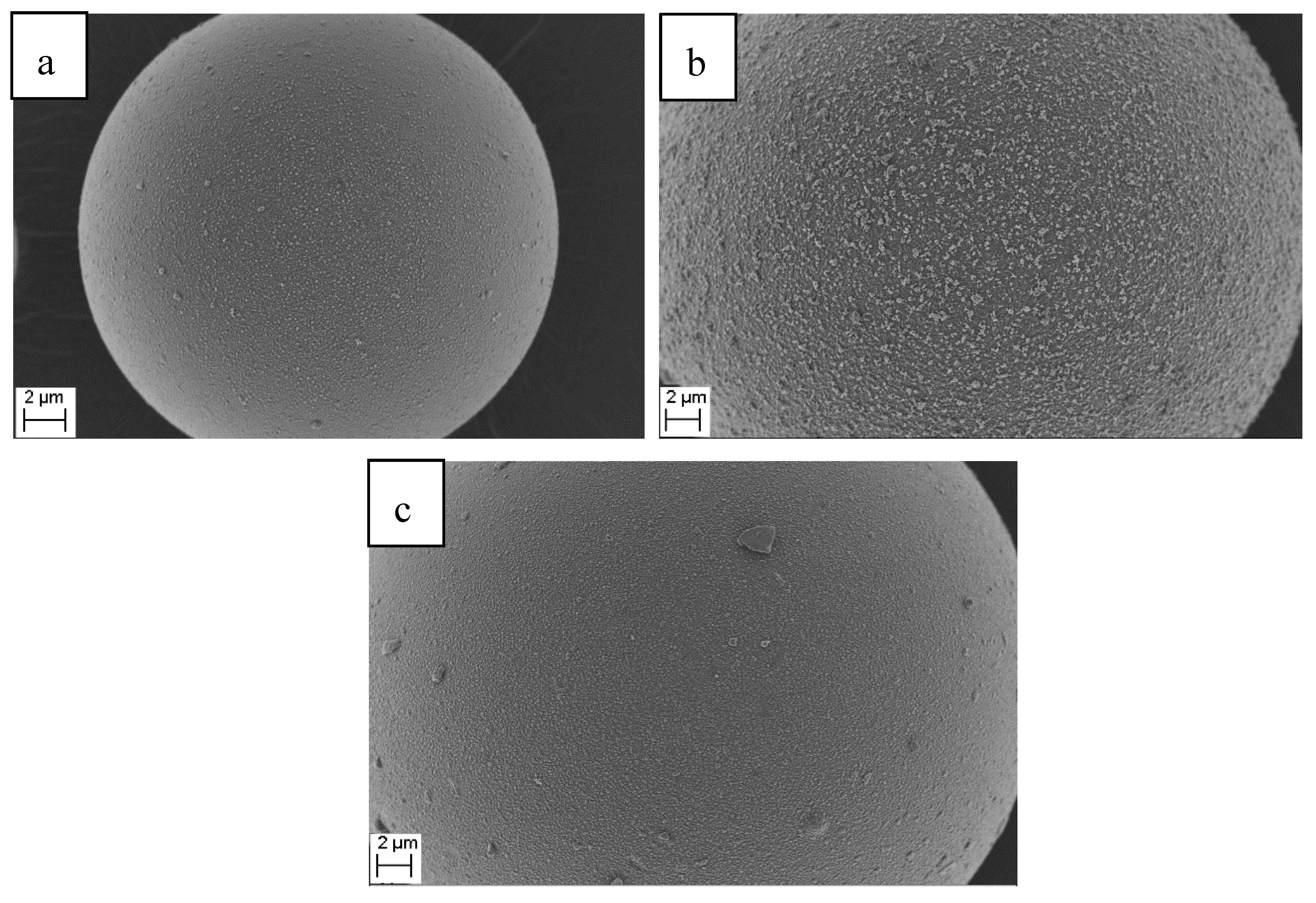
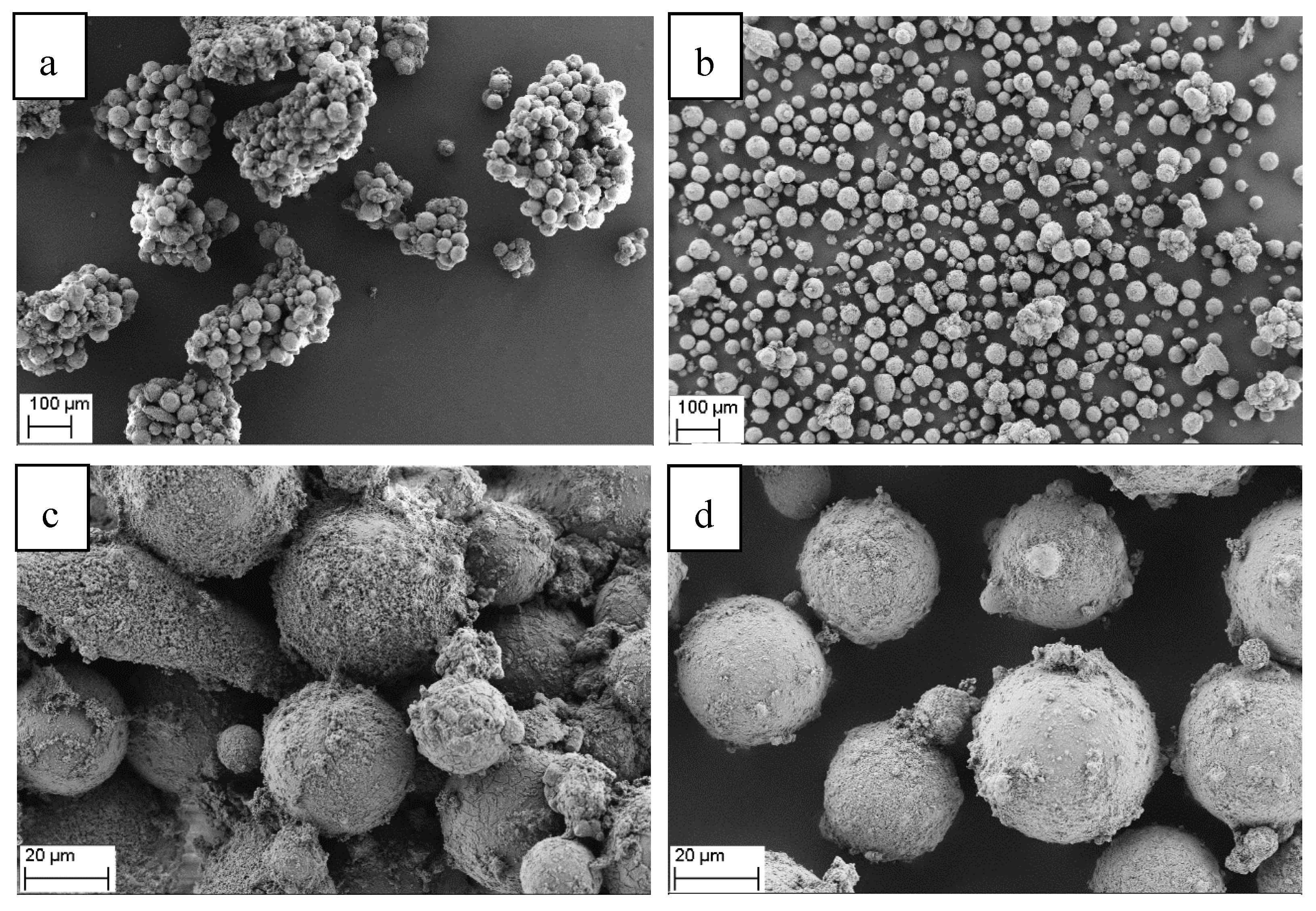
Figure 1 exemplarily shows SEM images of PVD-coated spheres with the highest layer thickness for each type. The entire surface of the spheres is uniformly coated with aluminum and no free spots are present. The surface morphology of the PVD-coated spheres is almost homogeneous with only small imperfections that may be caused either by impurities or by the anti-agglomeration-agent on the surface of the commercial spheres.
2.2. Liquid Phase Deposition (LPD)
2.2.1. Pre-Conditioning
In contrast to the PVD-coating process, the anti-agglomeration agent as well as possible impurities on the surface of the spheres may act as single seed particles during the LPD-coating process, which favor growth on single spots and thus lead to inhomogeneous layers. To create equal starting conditions for the LPD process and obtain preferably homogeneous aluminum layers, a two-step pre-conditioning of the spheres was performed. First, the MGS were washed three times with ethanol and distilled water, and then dried in a drying cabinet for 24 h at 80 °C to clean the surface of the spheres from impurities. To further support a homogenous coating with aluminum, a calcium silicate nanoparticle layer was created. Following Jin et al. [13], 10 g of the cleaned MGS were then dispersed into a saturated calcium hydroxide solution (Ca(OH)2, Sigma Aldrich) for 4 h at 90 °C. Afterwards, the spheres were filtered and again stored in the drying cabinet for 24 h at 80 °C before coating.
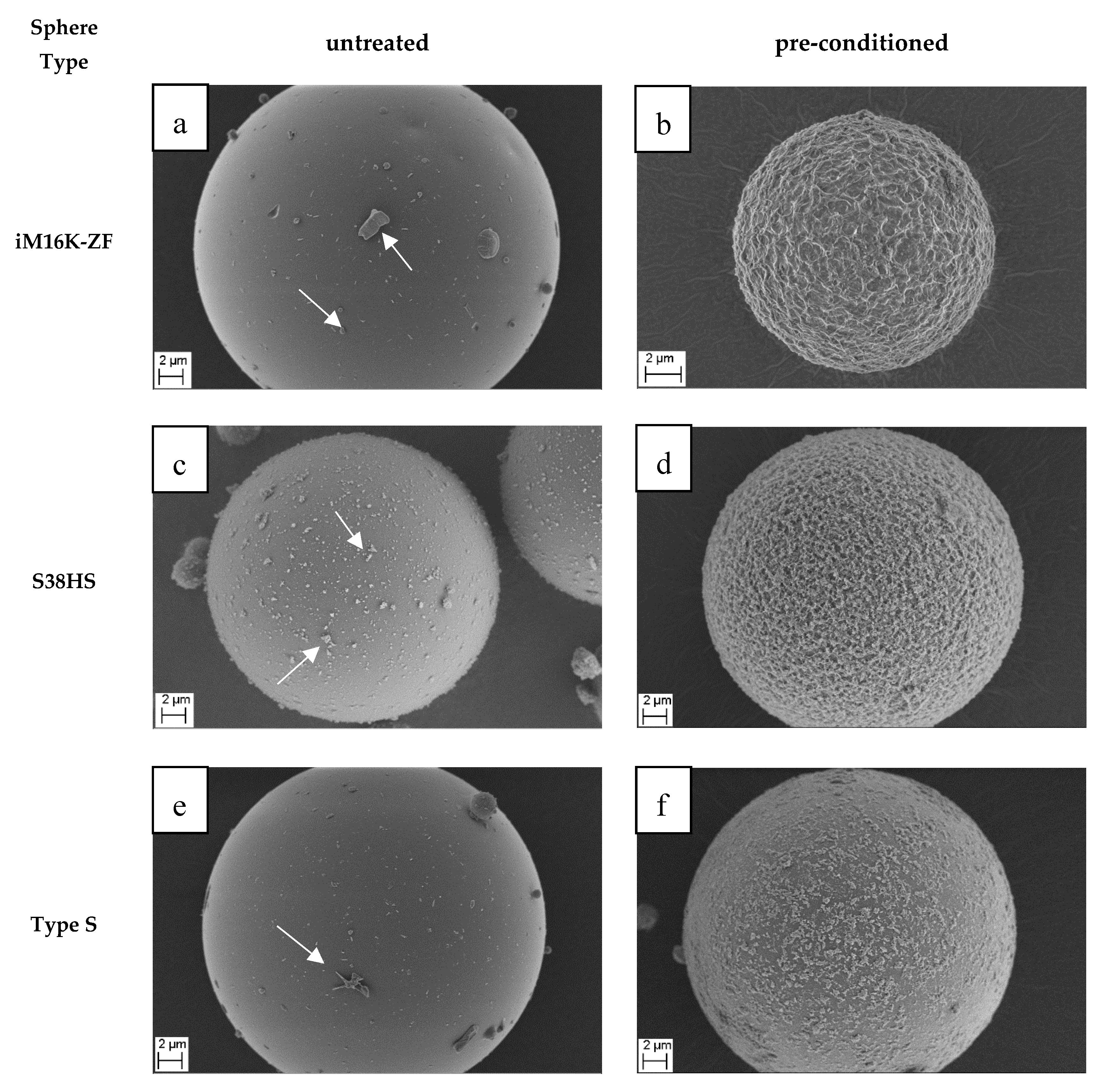
A comparison of untreated MGS to the pre-conditioned MGS is shown in SEM pictures in Figure 2. The untreated surface of the MGS is nearly smooth. The visible small agglomerates (indicated by the white arrows) are either impurities resulting of the manufacturing process, or in the case of the sphere type S38HS, the additional anti-agglomeration agent. After pre-conditioning, calcium silicate nanoparticles are deposited on the surface of the three sphere types. Nevertheless, it appears that more calcium silicate nanoparticles are deposited on the MHGS than on the surface of Type S. This may be due to the different glass types. It was additionally noticed that, for sphere type iM16K-ZF, it agglomerates with sizes of 10–20 spheres that occur after the pre-conditioning. This is explained by the absence of the anti-agglomeration agent. It is presumed that these small clusters are broken up by mechanical means in the later coating process, similar to the reference spheres.
2.2.2. LPD of Aluminum
The theoretical reaction step for the LPD of aluminum, as proposed by Lee et al [24] and Brower et al. [26], is shown in Equation (1), the individual reaction steps in Equations (2)–(4).
First the precursor aluminum trihydride dibutyl etherate is produced by reacting 3 M lithium aluminum hydride (LiAlH4, Sigma Aldrich) with 1 M aluminum chloride (AlCl3, Sigma Aldrich) in 2 × 50 mL of anhydrous dibutyl ether (Sigma Aldrich) for 120 min at room temperature (2) [21,22]. The generated precursor is then separated from the byproduct lithium chloride (LiCl) by filtration and subsequently mixed with the Micro Glass Spheres (MGS). Afterwards the precursor is decomposed at a reaction temperature of 130 °C (3,4), where, according to Equation (4), the aluminum supply is related to reaction time as well as the amount of the precursor.
The coating process itself was carried out with two different standard laboratory setups, which also seem appropriate for a technical scaling. In Setup 1, a round flask with magnetic stir bar and reflux condenser under nitrogen atmosphere was employed. Setup 2 comprises a rotating round flask also under a nitrogen atmosphere. For testing and optimizing the coating process of the MGS, several experiments were carried out (Table 3). First, SMGS were coated with different reaction times (120, 240, and 300 min) in both setups to determine a reasonable coating time. Due to the preprocessing step, 10 g of SMGS are employed in each attempt. By transferring this amount of spheres in a graduated cylinder, a bulk volume of 6.5 mL was determined, which has to be taken into account due to the different bulk densities of the investigated sphere types. In addition, experiments with the MHGS were also carried out in both setups.
2.2.3. Post-Treatment
As for the PVD-coated spheres, agglomerations were also observed in the PVD process. As mentioned before, the agglomerated spheres can be broken up by mechanical means. Therefore, different post-treatments were applied to the LPD-coated spheres to further investigate the disaggregation of clustered spheres. Simultaneously, a possible influence on the surface morphology and the stability of the aluminum coating on the sphere surface can be tested.
Turbula® Mixer:
Agglomerates of the PVD-coated spheres could be broken up by vibrational movement, so the LPD-coated spheres were first treated with a Turbula® Mixer (Willy A. Bachofen AG, Muttenz, Switzerland). Different mixing times (2, 4, 6, 8, 12, and 24 h) were investigated.
Magnetic Stir Bar Treatment:
To further examine the mechanical influence of the magnetic stir bar utilized in Setup 1, the coated spheres were placed in water and stirred for 12 h. Water was chosen as solvent as it allowed the simultaneous investigation of how the coated spheres behave in a slightly alkaline milieu. This behavior is interesting for a later possible use as additive in water-based wall paints.
Furnace Treatment:
In addition to the mechanical influences, a thermal influence on the coated spheres was also investigated.
A possible homogenization or smoothing of the coating layer by sintering or melting is pursued by heating up coated spheres in a furnace to different temperatures with a gradient of 10 °C/min in a forming gas (Ar/H2 95/5) atmosphere. Two temperatures below (400 and 500 °C) and one temperature above (750 °C) the melting temperature Tm of aluminum (approx. 660 °C) were chosen. The holding time was set to 2.5 h.
2.3. Experimental Characterization Methods
To determine coating quality and reflective properties, each batch of spheres was subjected to a detailed experimental investigation by the following characterization methods.
2.3.1. Qualitative Phase composition
The coating was analyzed by X-Ray structure analysis (XRD) to determine if pure aluminum was deposited on the surfaces of the spheres. It was carried out with an X’-Pert MPD PW 3040 X-ray diffractometer from Philips (Philips Co., Netherlands). The individual samples were measured using Cu Kα radiation in a range from 10–90° 2Θ. The step speed was 0.03° with a holding time of 30 sec. The obtained spectra were analyzed with the software X’ Pert High Score Plus 4.1 (Malvern Panalytical, Malvern, UK).
To analyze the elemental phase composition of the coating, an Energy Dispersive X-Ray analysis (EDX) was conducted. The measurements were carried out with a Thermo Fisher Ultra Dry SDD Silicium Drift Detector (Thermo Fisher, Darmstadt, Germany) with an excitation voltage of 20 kV.
2.3.2. Morphology Characterization
The morphology of the coated spheres was observed using a Zeiss LEO 1530 FESEM scanning electron microscope (SEM) (Zeiss, Oberkochen, Germany) at the Bavarian Polymer Institute (BPI) of the University of Bayreuth. The excitation voltage was set to 3 kV. In advance, the samples were sputtered with a 1.3 nm thick platinum layer by a 208HR sputter coater (Cressington Scientific Instruments, Dortmund, Germany).
2.3.3. Reflection Measurement
MIR-range reflection measurements were performed with a FTIR instrument (Vertex70 from Bruker Optic GmbH, Ettlingen, Germany) and an integrating sphere (U-Cricket TM-BR4 from Harrick Scientific Products, Darmstadt, Germany) under a nitrogen atmosphere against a gold standard. The measuring range of the Vertex 70 is approx. 600 to 7000 cm−1, which corresponds to a wavelength range of approx. 1.5 to 18 µm. The samples were applied as a monolayer to an adhesive strip and then placed on the opening of the integrating sphere. The reproducibility was confirmed by repeated preparation and measurements of the powder samples. An error of less than 0.01% was determined.
3. Results and Discussion
3.1. Morphological Examination
3.1.1. Setup 1—Round Flask with Magnetic Stir Bar
Experiment 1 was carried out in a round flask with a magnetic stir bar and reflux condenser under a nitrogen atmosphere. The color change from white to gray after each coating test qualitatively demonstrates the metallization of the spheres (Figure 3)
In Experiment 1 A coating tests with 10 g of spheres of Type S and coating times of 120, 240, and 300 min were performed. As indicated in Figure 4, a coating is achieved for all investigated times. However, an increased coating time leads to smoother surfaces. The interaction of the friction of the magnetic stir bar, which is used for mixing of the coating solution during the coating process, and the necessary reaction time for a complete decomposition are identified as possible reasons.
After 120 min, the reaction does not seem to be completed, and therefore, additional aluminum was deposited on the surface of the spheres despite the friction of the stir bar. Between 120 and 240 min, however, the reaction was completed and the friction of the stir bar smoothed the surface. It also becomes clear that the aluminum must be firmly fixed to the sphere surface, since no abrasion of the coating takes place. This will be examined more closely in the section of the post-treatment (3.1.3). As only little differences are obtained between coating times of 240 and 300 min, the coating time of 240 min was chosen for further experiments.
Compared to the PVD-coated spheres, coating times of 240 and 300 min results in a homogeneous coating and smooth surface morphology. The uniform application of the aluminum coating is also confirmed by the EDX mapping. The results of X-Ray diffraction analysis are plotted in Figure 5. The uncoated spheres show an amorphous halo in the range of 20–40 Θ, which is characteristic for amorphous materials like glass. Besides the halo, the aluminum coated samples deliver characteristic peaks of metallic aluminum at 38° (111), 45° (200), 65° (220), 78° (211), and 82°(222). Thus, it can be verified that pure metallic aluminum is deposited on the sphere surfaces with the liquid phase deposition (LPD) method.
Exemplary EDX-Mapping-Measurements (d) of a coated sphere of Type S (Experiment 1) shows a uniform aluminum coating (red) on the surface of the spheres after a coating time of 240 min.
While for the spheres of Type S a rather homogenous and smooth coating was possible, attempts to coat the MHGS spheres type S38HS with Setup 1 was not successful. Contrary to the SMGS, the MHGS are floating on top of the reaction solution due to their significant lower density. To enforce a complete mixing, the speed of the magnetic stir bar had to be increased. The higher shear forces caused an increased breakage of the spheres, especially for type S38HS. This is justified by the low compressive strength of this sphere type (Table 1). Due to the higher compressive strength, type iM16K-ZF did not show an increased sphere breakage under these conditions, but a strong agglomeration and a very inhomogeneous coating were observed.
3.1.2. Setup 2—Rotating Flask
To eliminate the damage of the spheres by the magnetic stir bar and the influence of floating, especially for the MHGS, Experiment 2 A and 2 B were carried out in a rotating flask under nitrogen atmosphere. Again, 10 g or 6.5 mL of spheres of Type S were coated to obtain a comparison to the results attained with round flask and magnetic stir bar. Figure 6 left exemplarily shows a SEM image of a coated sphere of Type S. Compared to Setup 1 partly bigger agglomerations stick on the surface (indicated by white arrows). In addition, clumping of the spheres take place. This is explained with the absence of the magnetic stir bar, which smooths the surfaces of the spheres by friction and probably is breaking up agglomerates. This will be examined in more detail in Chapter 3.1.3. Nevertheless, also uniform coated spheres could be obtained with Setup 2, which is confirmed by the EDX mapping (Figure 6b).
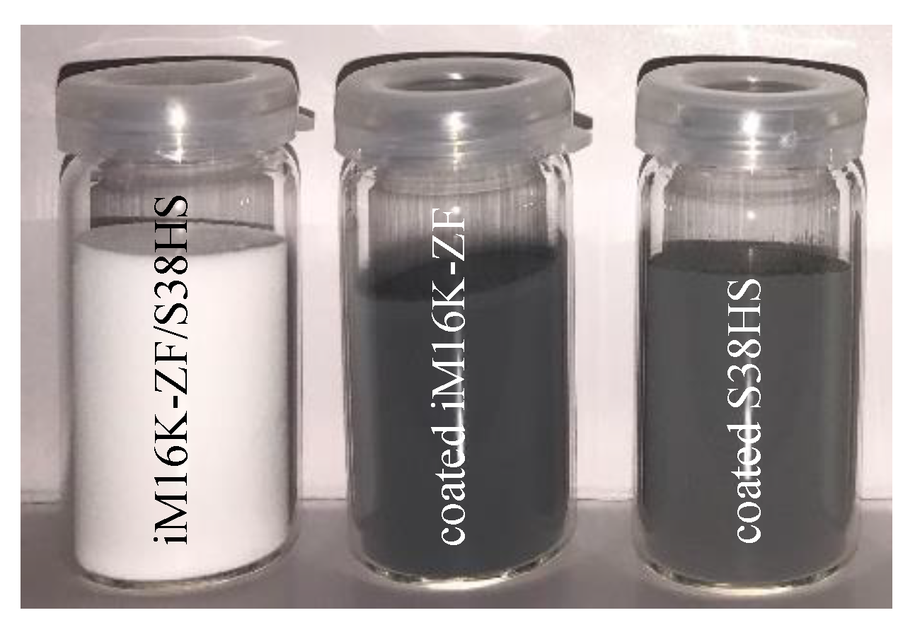
In Experiment 2 B a defined volume of 6.5 mL of each type of MHGS was coated. The color change of the spheres from white to gray after each coating test once again also indicates a successful metallization of the spheres (Figure 7).
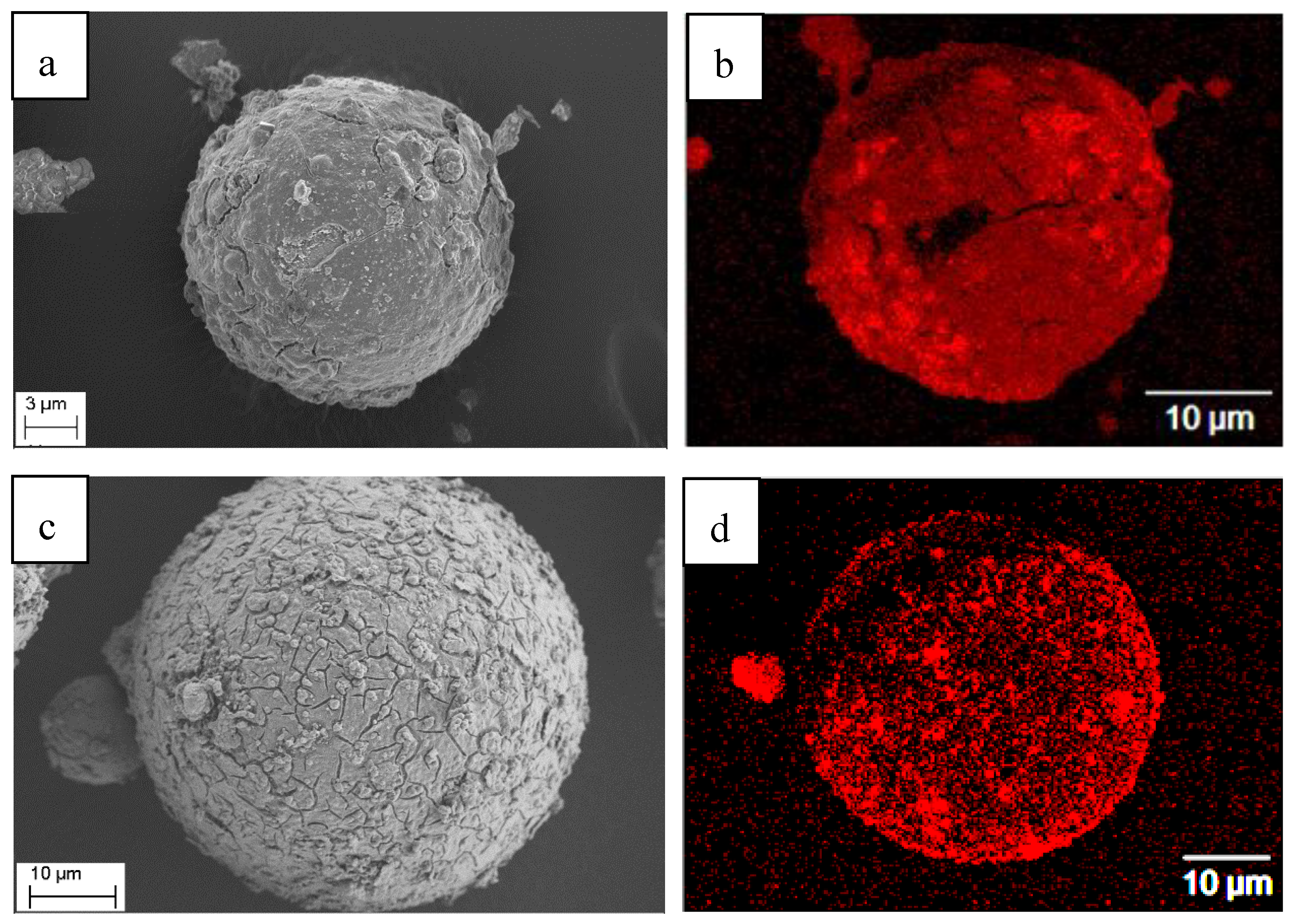
SEM images and EDX mappings in Figure 8 confirm that a homogenous coating on both types of MHGS can be reached in Experiment 2B. No ball breakage occurs. The XRD results again indicate a metallic aluminum coating (Figure 9).
In comparison with the reference spheres and the coated spheres of Type S of Experiment 1 A, however, a more structured morphology results. This is explained by the reduced friction in the rotary flask compared to the stirring, which led to a smoother surface structure in Experiment 1. In addition, both types of MHGS now show a partly agglomeration (10–20 spheres). This, nonetheless, is not a problematic result as the post-treatment is intended to break up these agglomerates.
3.1.3. Post-Treatment
In the previous chapters, it was shown that, with the LPD-method, it is possible to metallize a rather uniform aluminum layer on micro hollow and micro solid glass spheres. Different results regarding layer morphology were achieved and partly agglomeration was observed. As agglomerates of PVD-coated spheres could be broken up by mechanical means, additional post-treatments were carried out to investigate whether the small agglomerates of the LPD-coated spheres can also be broken up by mechanical means. In addition, the stability of the coating as well as the surface morphology after the treatments were examined. Coated sphere types iM16K-ZF and Type S of Experiment 2 were used for the post-treatments.
As already investigated, friction by the magnetic stir bar effects a smoothing of the aluminum coating of the SMGS, whereas MHGS show increased ball breakage. Friction in the rotating flask caused no breakage of the MHGS but is not sufficient to smooth the aluminum coating. Therefore, the rotating friction, simulated in a Turbula® Mixer, is increased by raising the time in order to achieve a smoothing effect. In addition, agglomerated spheres could be broken up. Hence, the coated spheres were first treated in a Turbula® Mixer for different times (2, 4, 6, 8, 12, and 24 h).
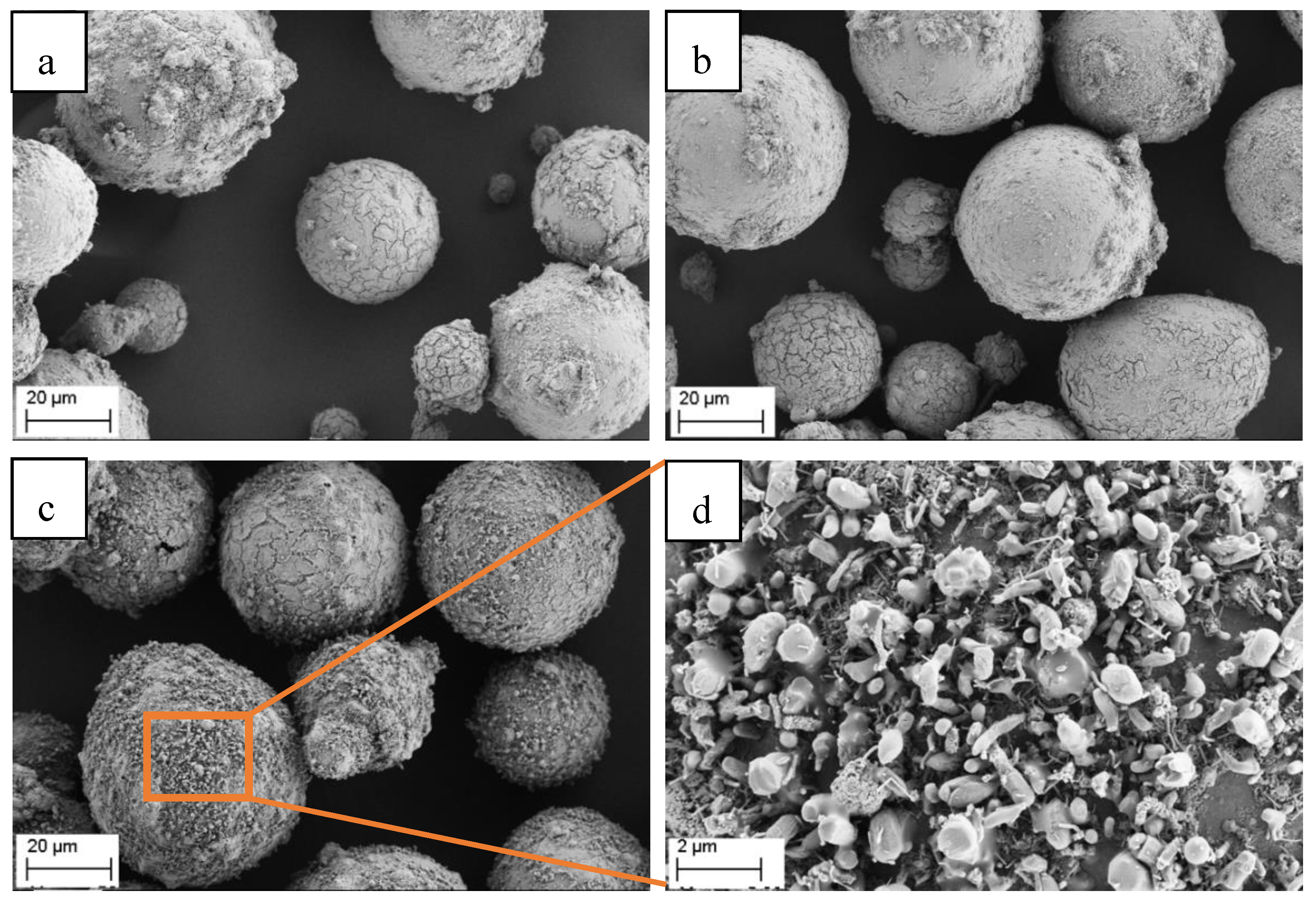
Figure 10 exemplarily shows SEM-images of spheres of Type S treated for 24 h. The agglomerates present in the untreated sample are almost completely broken up by the treatment. This can also be seen with sphere type iM16K-ZF. Thus, with Setup 1 and Setup 2, single coated spheres can be obtained. This is advantageous, because single coated MGS can be processed more easily. Further, the overall surface is increased, which is positive for the reflective behavior. In addition, there is also a small change in the surface morphology. The previously structured surface can be smoothed slightly, which in turn again can have a positive effect on the reflective behavior. The aluminum coating is firmly bonded to the surface of both spheres, and no break off of the coating results by friction. This can have a positive influence on the potential use in wall paints, where fillers are also included in paints by mixing.
A second post-treatment method was carried out to investigate the influence of the magnetic stir bar in Setup 1. It was already shown that the magnetic stir bar breaks up the agglomerates during the coating process and smooths the surface of the spheres. It was tested whether this is also possible afterwards for coated spheres of Setup 2. Therefore, coated spheres of Type S (Experiment 2A) were transferred into distilled water and stirred for 12 h. As explained above, distilled water was used to equally test the influence of a slightly basic milieu. No color change of the post-treated spheres occurs, which means that no influence on the aluminum layer results from the slightly basic milieu. Again, the agglomerates could be broken up by the post-treatment with magnetic stir bar. Additionally, it can be recognized in Figure 11 that there is a partially significant change of the surface structure. On some spheres, a very smooth surface, like in Experiment 1, results. The fact that it only occurs partially may be due to different sphere-solvent ratios (2 g/100 mL) compared to the coating test (10 g/100 ml). Thus, it is possible that not all spheres get the same level of friction. This treatment, however, could only be carried out with the spheres of Type S, as the problem of floatation occurred with the sphere type iM16K-ZF.
Considering the stability of the coating, no flaking or destruction of the aluminum layer took place even after 12 h. Thus, the aluminum coating sticks firmly on the surface of the spheres of Type S and can also be smoothed by a post-treatment with a magnetic stir bar.
Since the agglomerates can be broken up and the surface morphology can be changed by friction, a third treatment was carried out to investigate whether a thermal treatment has an influence on the morphology of the coating, too. As already shown in Experiment 2 the coated spheres showed a more structured surface morphology. The furnace treatment is intended to show whether smoothing the coating is possible by sintering or melting. Therefore, the post-treatment method consists of heating up the coated spheres to different temperatures (400, 500 and 750 °C, 10 °C/min, no holding time, Ar/H2 95/5 atmosphere) in a furnace.
Exemplarily SEM images of coated Type S spheres are shown in Figure 12. For furnace temperatures of 400 and 500 °C no significant change of the aluminum layer occurs. Agglomerates of single spheres were formed, indicating that a sintering of the layer took place. The sticking together could possibly be prevented by a rotating chamber. However, the temperature is not sufficient to completely smooth the aluminum layer on the surface of the spheres. For a furnace temperature of 750 °C, in contrast, a noticeable change in the aluminum layer can be detected. Smaller crystal-like and worm-like structures were formed, which makes the sphere surface much more inhomogeneous than it was before. This structural change is caused by the recrystallization of aluminum, as was also described from K. D. Vanyukhin et al. [27]. A melting and thus a smoothing of the coating does not take place.
Since neither friction nor heat causes a break off or flaking of the aluminum layer, it can be assumed that a stable aluminum coating results from the LPD method. A positive effect of the post-treatment with the Turbula® Mixer and the magnetic stir bar, that agglomerates can be broken, which makes the spheres more easily processable and increases in reflective surface. Additionally, a partially significantly change in surface morphology occurred for the coated SMGS. Thus, through sufficient friction, a smooth coating morphology, similar to that of the reference spheres, can be achieved on solid glass spheres.
3.2. Reflection Measurements
In Chapter 3.1, it was shown that it is possible to get a rather homogeneous aluminum coating on micro hollow and solid glass spheres with the LPD method. Since the aim of the work is not only to investigate the possibility to metallize the MGS, but also to explore the increase of the reflection in the MIR wavelength range, reflection measurements were carried out in addition to the optical and morphological evaluation using SEM images and as well as XRD and EDX. The question whether the reflection can be increased due to the properties of aluminum in contrast to the uncoated MGS was investigated. Further, the reflectance of the LPD-coated spheres and PVD-coated spheres was compared to examine the influence of different surface morphologies.
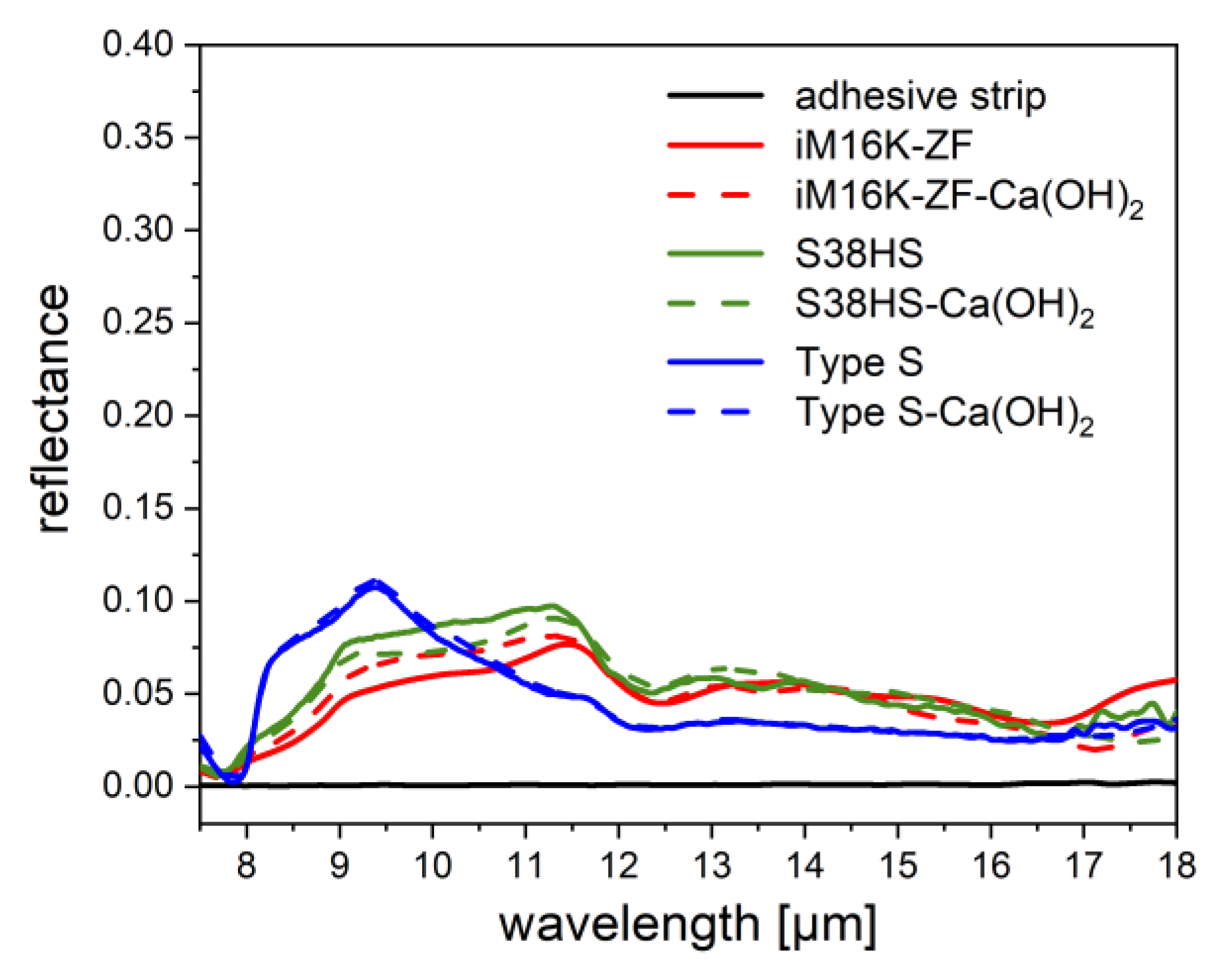
As an adhesive strip is utilized to apply the powdery samples to the opening of the integrating sphere of the measurement device, a possible influence of the strip was first examined. As can be seen in Figure 13 (black curve), the adhesive strip has a nearly 0% reflectance in the chosen measurement range between 7.5 and 18 µm and thus can be neglected. The samples were sieved beforehand to ensure that only coated spheres and no Al dust were measured. Furthermore, the influence of the pre-conditioning with Ca(OH)2 was investigated by comparing the reflectance of pre-conditioned MHGS and SMGS with untreated spheres in the same range (Figure 13). Below 10 µm, soda-lime and borosilicate glasses have absorptions bands, above reflectance values between 3% and 10% arise.
The influence of the pre-conditioning can be neglected for the sphere type Type S, since the pre-conditioned micro spheres exhibit nearly the same reflectance in the wavelength range of interest as the original spheres (Figure 13, blue curves). For the sphere types iM16K-ZF (Figure 13, red curves) and S38HS (Figure 13, green curves), a slight difference in the reflection can be observed between 9 and 11 µm and for wavelengths greater than 17 µm. The latter one is explained by the resolution limit of the device, the differences in the smaller wavelength range may be due to an inhomogeneous coating.
3.2.1. PVD-Coated Spheres
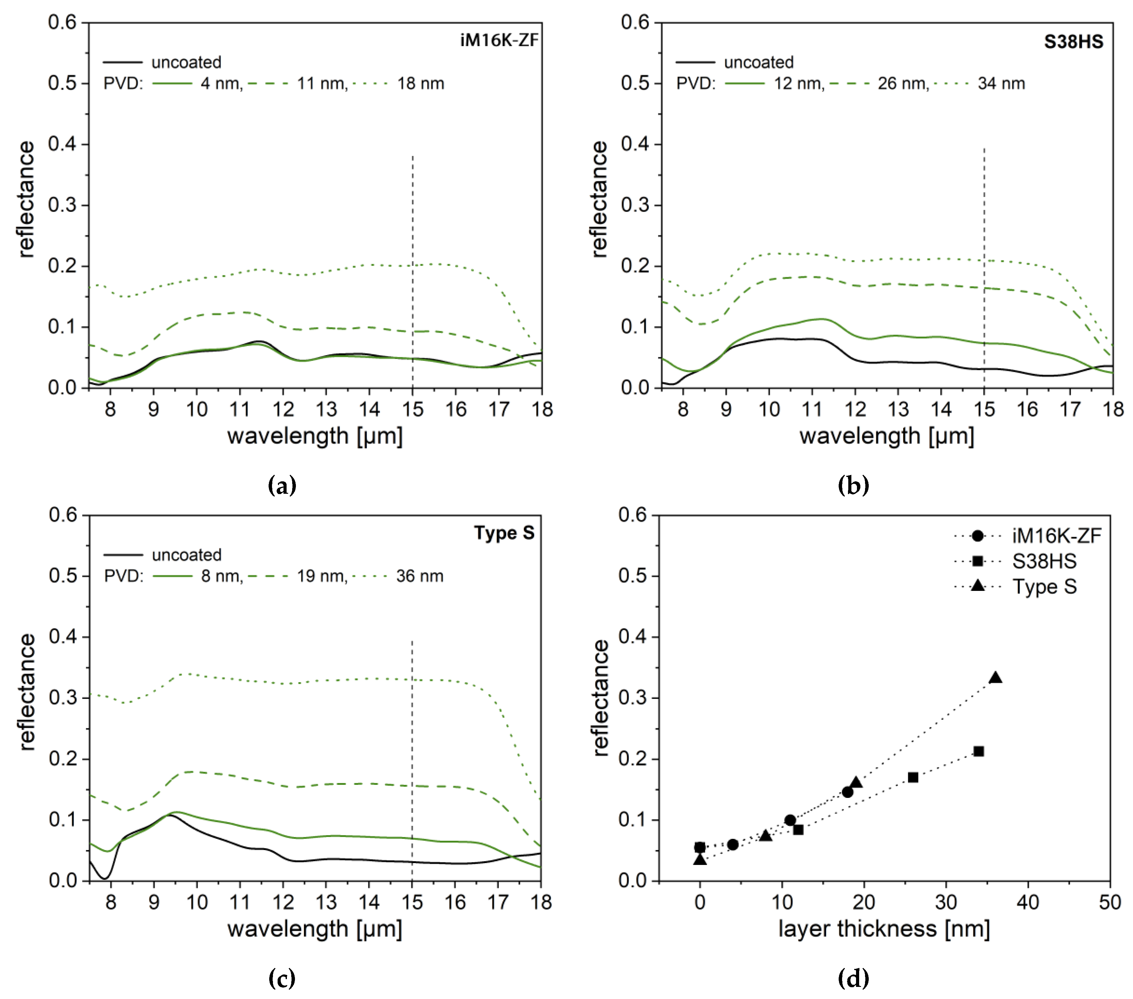
First, the reflectance values of the PVD-coated reference spheres were determined with the described setup and a correlation between different layer thicknesses and reflection was evaluated. At lower layer thicknesses, the curve still resembles the reflection curve progression of uncoated spheres. With increasing layer thickness, almost constant reflection values emerge, which is typical for aluminum (Figure 14a–c). Thus, the almost constant curve-shape indicates a sufficient deposition of aluminum on the surface of the spheres, as no features of glass reflection are observed any more [23]. The decrease in reflectance observed for wavelength values greater than 17 µm is again related to the resolution limit of the measurement device.
It becomes apparent that, with the increasing layer thickness, an increase in reflection also takes place for all three sphere types. To show this more clearly, in Figure 14d the reflectance values of each sphere type at a wavelength of 15 µm is plotted against the layer thickness. A similar behavior was observed by Lugolole et al. [20]. Interestingly, a similar layer thicknesses of approx. 36 nm lead to different reflectance values. A higher reflection degree of the SMGS in comparison to the MHGS is achieved.
3.2.2. LPD-Coated spheres—Setup 1
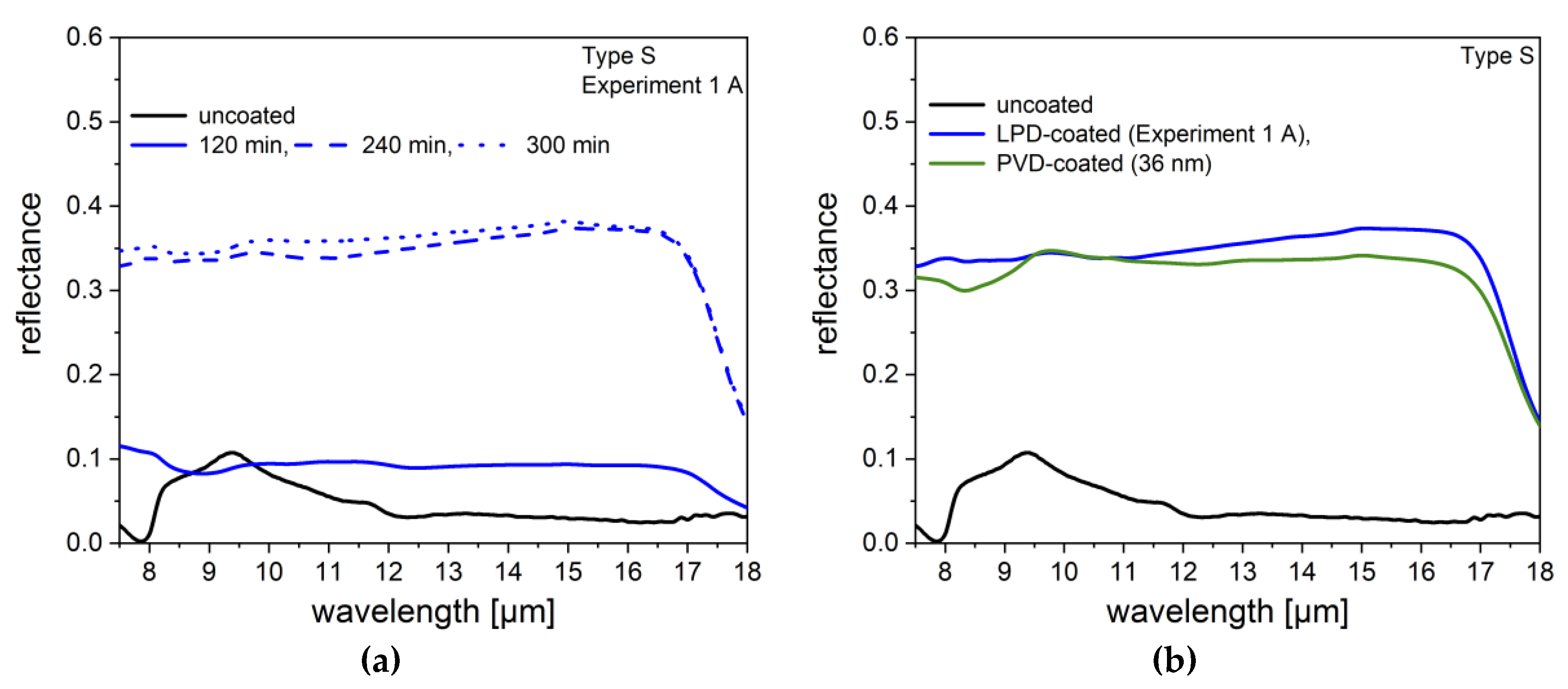
In Figure 4, it was already shown that a very homogeneous, smooth aluminum coating can be achieved with Setup 1 and a coating time of 240 min for the spheres of Type S. The results of the reflection measurements of these LPD-coated spheres and the comparison with the PVD-coated spheres are represented in Figure 15.
Considering the reflectance measurements, it can be seen that a significant increase in reflectance is observed as a function of the coating time from approx. 5% to 35%. However, after a coating time of 300 min, no more increase of the reflectance occurs in comparison to a coating time of 240 min. It was already examined in Chapter 3.1.1, how this is in the line with no change in surface morphology of the two samples, as the available aluminum has already been completely deposited.
Compared to the reflectance of the reference spheres (layer thickness 36 nm) similar values are achieved for the LPD-coated spheres. Thus, using the LPD method for Type S, both a similar surface morphology and reflectance in comparison to the PVD-coated Type S can be obtained.
3.2.3. LPD-Coated spheres—Setup 2
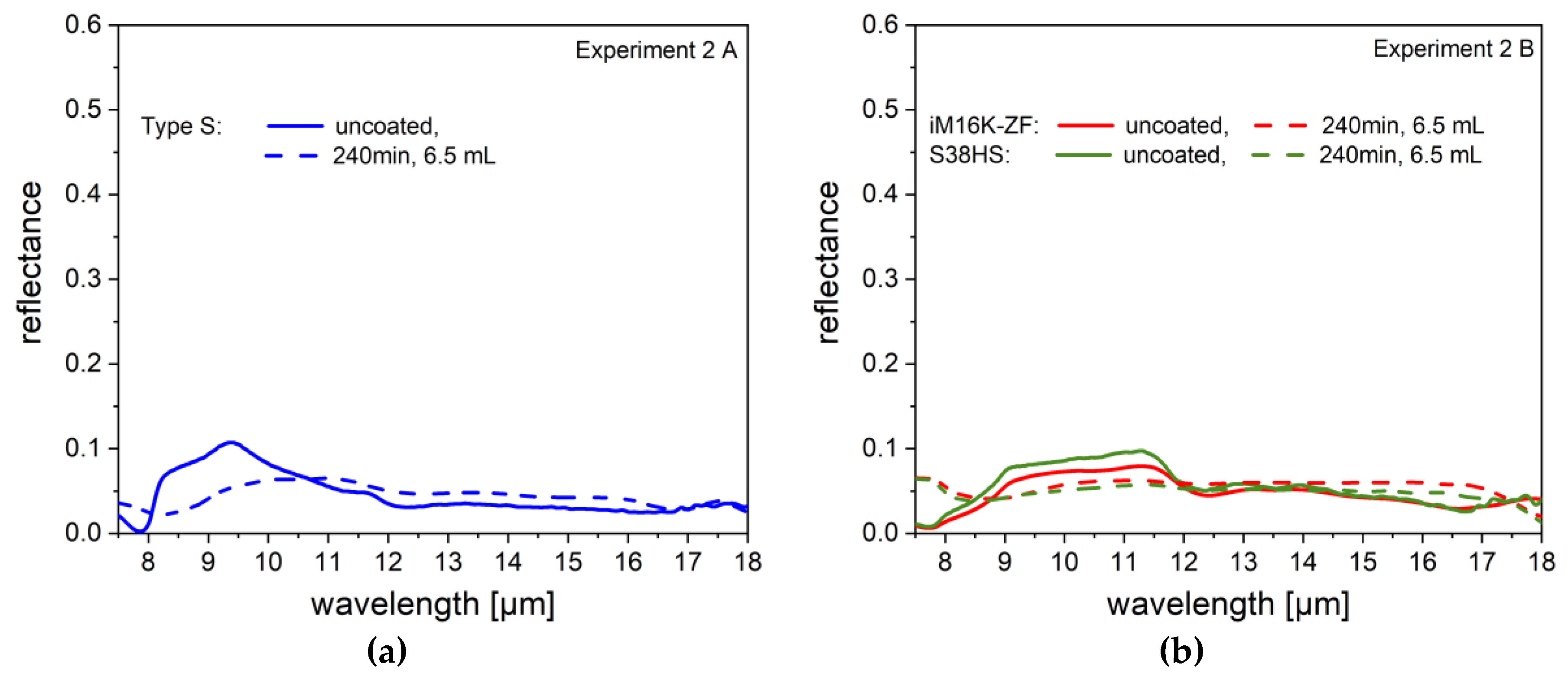
The results of the reflectance measurements of the coated spheres from Experiment 2 are shown in Figure 16. It was already established by SEM images Figure 6 and Figure 8 that all three types of spheres could be coated with aluminum, but in comparison to the reference spheres, a partly rougher surface morphology occurs. Despite the coated layer, for both types of spheres, no or less reflectance increase can be observed. This behavior was already established by Lugolole et al. [20], where the lowest reflectance was achieved with the sample, which has a rough surface. Das et al. [28], Moushumy et al [29], and Sharma et al [30] also show numerical simulations of different nano-structured gratings on GaAs substrates, that the surface structure has a significant influence on the reflection behavior. With a flat substrate, a reflection of about 28% can be achieved, whereas a structured surface shows only a reflection of about 2% [28].
Nevertheless, the reflectance curves of the coated spheres show an almost constant progress over the wavelength range and compensate at least partially the reflectance curve of the uncoated glass. This indicates that at least a sufficient amount of aluminum is coated on the spheres. Therefore, the uneven layer structure of the aluminum coating must be the determining factor.
3.2.4. Post-Treated Spheres
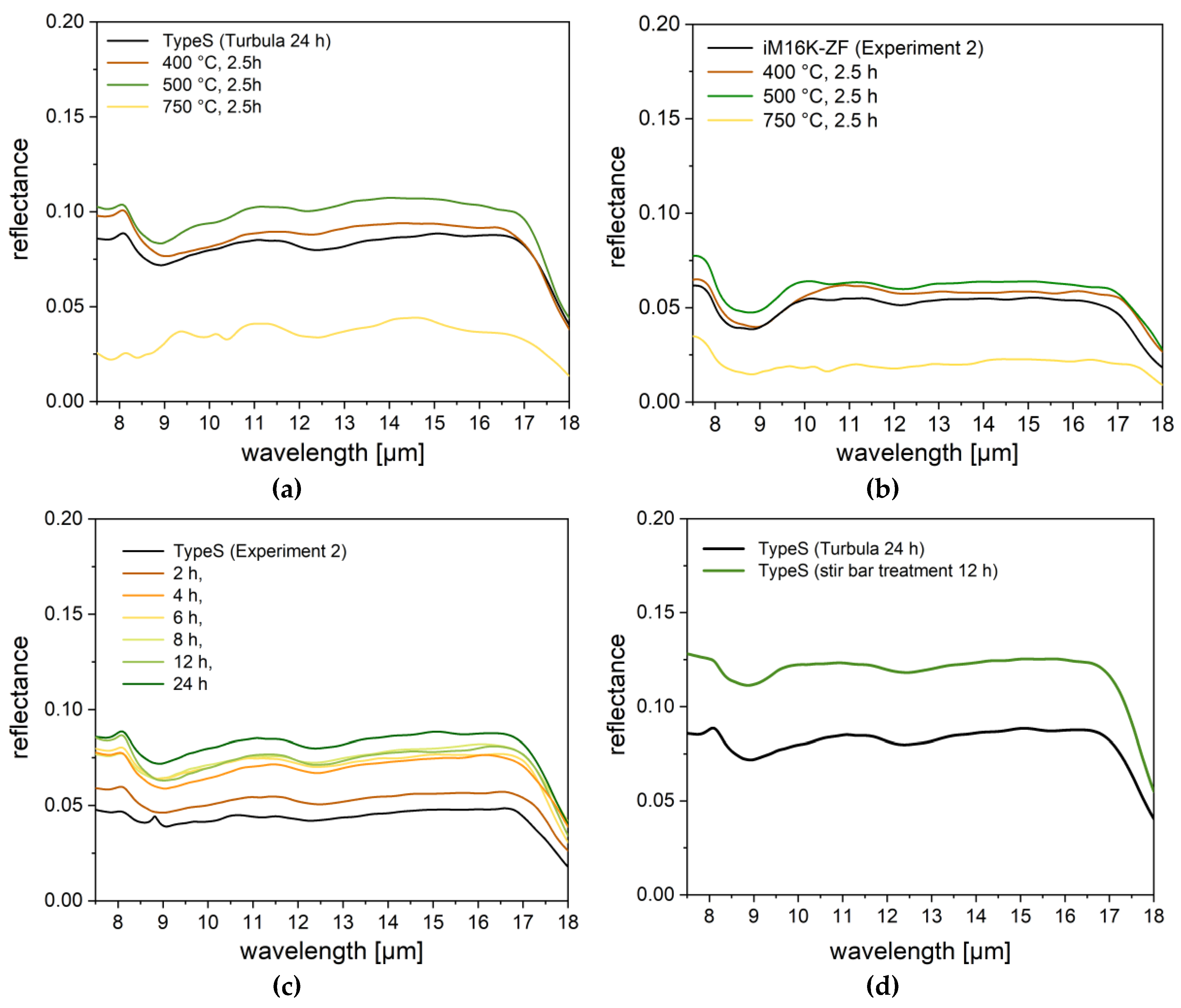
As can be seen in Figure 17, the reflectance can generally be increased by all three post-treatments. They led to a partial change in surface morphology towards smoother surfaces. Only in the case of the furnace treatment over the melting temperature of aluminum, a surface deterioration was observed. Here the dependence of reflectivity surface can again be clearly determined. The very inhomogeneous surface structure (Figure 12a,b) which is reflected in a clear decrease in reflectance to almost 1%. On the contrary, the furnace treatment below the melting point is associated with a reflection increase of approx. 3% (Type S) and approx. 2% (iM16K-ZF), despite no change in the SEM images was observed. The partially smoothed surfaces after magnetic stir bar treatment lead to a slightly better increase of 5% (Figure 17c). Besides surface smoothening, agglomerates of spheres could be broken up by mixing. This also should increase the reflection of the spheres due to the enlargement of the total surface. After 24 h in the Turbula® Mixer, an actual increase in reflection of approx. 3% occurred for the spheres of Type S (Figure 17d). For type iM16K-ZF a similar increase of 2% could be achieved. Thus, the dissembling of the agglomerates not only facilitates the processability, but also leads to an increase in reflectance.
In conclusion, the reflection measurements show that a change in morphology and thus an increase in reflection can be achieved through post-treatments. Despite the post-treatments, however, the result from Experiment 1 could not be tied up. Therefore, further works will be required to find a post-treatment that adapts the surface morphology for the coated MGS from Setup 2.
4. Summary
In this paper, the Liquid Phase Deposition (LPD) method was examined as an additional coating method to the Physical Vapour Deposition (PVD) and the Chemical Vapor Deposition (CVD) method for metallization of micro glass spheres. Two different micro hollow glass sphere types (MHGS, iM16K-ZF and S38HS) and one micro solid glass sphere type (SMGS, Type S) were coated with aluminum by the hydridolyse of AlCl3. Measurements of X-Ray Diffraction (XRD), Energy Dispersive X-Ray Spectroscopy (EDX) and Scanning Electron Microscope (SEM) show, that both sphere types (MHGS and SMGS) can be coated with metallic aluminum using the Liquid Phase Deposition (LPD) method. In comparison to reference spheres, coated via the Physical Vapor Deposition (PVD) method, a similar surface can be achieved for the SMGS, whereas a more structured morphology occurred for the MHGS. Post-treatments with Turbula® Mixer, magnetic stir bar and furnace exhibit that the aluminum layer is stable and firmly bonded to the sphere surface. In addition, the post-treatments were able to break up agglomerates, as well as slightly smooth the surface morphology.
The influence of the coating and the post-treatments on the reflective properties in the MIR-range of the spheres was examined by additional reflection measurements in a wavelength range of 7.5 to 18 µm. It was found that in addition to a sufficient amount of aluminum, surface properties play an important role. With a rather rough surface morphology, only an increase in reflectance of approx. 5% was observed for SMGS. In contrast, a very homogenous smooth surface resulted in an increase in reflectance of approx. 30 % compared to the uncoated spheres, which corresponds to the reflectance of the PVD-coated spheres. However, this cannot be obtained with the MHGS. However, the post-treatments showed that an adaptation of the surface morphology is possible, leading to double the reflectance compared to the untreated coated spheres.
The paper showed that the LPD method, as a non-vacuum process, is suitable for an aluminum coating of spherical particles. It was even possible to achieve coating results comparable to the PVD process, which was shown by the similar reflection values of the LPD-coated spheres and PVD-coated spheres. Besides reflection, aluminum coated (hollow) glass spheres can also be interesting for further application, e.g., the modification of thermal conductivity or dielectric properties, where, unlike in our case, the surface condition will have less influence.
Author Contributions
L.S. performed the experiments and wrote the paper. L.Z. and B.S. helped with the experiments. S.L. und T.G. provided guidance and helped in manuscript preparation.
Funding
Financial support by the BMBF project EcoSphere (BMBF: 13N13188) is gratefully acknowledged.
Acknowledgments
The presented work is dedicated to Monika Willert-Porada, who passed away on 11 December 2016. She initiated the above-mentioned project. In addition, the authors would like to thank Angelika Kreis and Ingrid Otto for laboratory support. The authors also want to thank Andreas Eder from the University of Vienna for producing the PVD-coated spheres. This publication was funded by the German Research Foundation (DFG) and the University of Bayreuth in the funding program Open Access Publishing.
Conflicts of Interest
The authors declare no conflict of interest.
References
- Wypch, G. Handbook of Fillers; Chem Tec Publishing: Toronto, ON, Canada, 2016; p. 4. ISBN 9781895198911. [Google Scholar]
- Kulshreshtha, A.K.; Vasile, C. Handbook of Polymer Blends and Composites; Rapra Tehnology Ltd.: Shrewsbury, UK, 2003; p. 4B. ISBN 9781859573044. [Google Scholar]
- He, D.; Jiang, B. The elastic modulus of filled polymer composites. J. Appl. Polym. Sci. 1993, 49, 617. [Google Scholar] [CrossRef]
- Lee, J.; Yee, A.F. Fracture of glass bead/epoxy composites: On micro-mechanical deformations. Polymer 2000, 41, 8363–8373. [Google Scholar] [CrossRef]
- Yung, K.C.; Zhu, B.L.; Yue, T.M.; Xie, C.S. Preparation and properties of hollow glass microsphere-filled epoxy-matrix composites. Compos. Sci. Technolol. 2009, 69, 260–264. [Google Scholar] [CrossRef]
- Xu, N.; Dai, J.; Zhu, Z.; Huang, X.; Wu, P. Synthesis and characterization of hollow glass–ceramics microspheres. Ceram. Int. 2011, 37, 2663–2667. [Google Scholar] [CrossRef]
- Li, B.; Yuan, J.; An, Z.; Zhang, J. Effect of microstructure and physical parameters of hollow glass microsphere on insulation performance. Mater. Lett. 2011, 65, 1992–1994. [Google Scholar] [CrossRef]
- Drobny, J.G. Handbook of Thermoplastic Elastomers; Elsevier: Amsterdam, The Netherlands, 2014; Volume 1, p. 25. ISBN 9780323221368. [Google Scholar]
- Weatherhead, R.G. FRP Technology Fibre Reinforced Resin Systems; Springer: Berlin/Heidelberg, Germany, 2012; Volume 1, p. 381. [Google Scholar] [CrossRef]
- Budov, V.V. Hollow Glass Microspheres. Use, Properties and Technology (Review). Glass Ceram. 1994, 51, 230–235. [Google Scholar] [CrossRef]
- Lehmann, S.; Schwinger, L.; Scharfe, B.; Gerdes, T.; Erhardt, M.; Riechert, C.; Fischer, H.-B.; Schmidt-Rodenkirchen, A.; Scharfe, F.; Wolff, F. Mikro-Hohlglaskugeln als Basis Energieeffizienter Dämmung von Gebäuden. In Proceedings of the HighTechMatbau Conference, Berlin, Germany, 4–5 December 2018; p. 21. [Google Scholar]
- Kemsley, J.N. What’s that stuff? Road Markings-Pigments, polymers, and reflective spheres help keep you safe on the road. Chem. Eng. News 2010, 88(36), 67. [Google Scholar]
- Jin, H.; Xu, D.; Li, J.; Wang, K.; Bi, Z.; Xu, G.; Xu, X. Highly Solar-Reflective Litchis-Like Core-Shell HGM/TiO2 Microspheres Synthesized by Controllable Heterogeneous Precipitation Method. NANO Brief Rep. Rev. 2017, 12, 1750080. [Google Scholar] [CrossRef]
- Willert-Porada, M. (Ed.) Second Progress Report Forglas; Subproject I.2; Universität Bayreuth: Bayreuth, Germany, 2011; pp. 51–74. [Google Scholar]
- Mohelnikova, J. Materials for reflective coatings of window glass applications. Constr. Build. Mater. 2009, 23, 1993–1998. [Google Scholar] [CrossRef]
- Cozza, E.S.; Alloisio, M.; Comite, A.; di Tanna, G.; Vicini, S. NIR-reflecting properties of new paints for energy-efficient buildings. Sol. Energy 2015, 116, 108–116. [Google Scholar] [CrossRef]
- Zhang, H. Silver plating on hollow glass microsphere and coating finishing of PET/cotton fabric. J. Ind. Text. 2012, 42, 283–296. [Google Scholar] [CrossRef]
- Xu, X.; Luo, X.; Zhuang, H.; Li, W.; Zhang, B. Electroless silver coating on fine copper powder and its effects on oxidation resistance. Mater. Lett. 2003, 57, 3987–3991. [Google Scholar] [CrossRef]
- Morales, A.; Durán, A. Sol-Gel Protection of Front Surface Silver and Aluminum Mirrors. J. Sol-Gel Sci. Technol. 1997, 8, 451–457. [Google Scholar] [CrossRef]
- Lugolole, R.; Obwoya, S.K. The Effect of Thickness of Aluminium Films on Optical Reflectance. J. Ceram. 2015, 2015, 1–6. [Google Scholar] [CrossRef] [Green Version]
- Eder, A.; Schmid, G.H.S.; Mahr, H.; Eisenmenger-Sittner, C. Aspects of thin film deposition on granulates by physical vapor deposition. Eur. Phys. J. 2016, 70, 247. [Google Scholar] [CrossRef]
- Schmid, G.H.S.; Eisenmenger-Sittner, C. A method for uniformly coating powdery substrates by magnetron sputtering. Surf. Coat. Technol. 2013, 236, 353–360. [Google Scholar] [CrossRef]
- Park, J.-H. Chemical Vapor Deposition. In Surface Engineering Series Volume 2; ASM International: Almere, The Netherlands, 2001; pp. 1–3. ISBN 0-87170-731-4. [Google Scholar]
- Lee, H.M.; Choi, S.-Y.; Kim, K.T.; Yun, J.-Y.; Jung, D.S.; Park, S.B.; Park, J. A Novel Solution-Stamping Process for Preparation of a Highly Conductive Aluminum Thin Film. Adv. Mater. 2011, 23, 5524–5528. [Google Scholar] [CrossRef] [PubMed]
- Houghton, J. The Physical of Atmopsheres, 3rd ed.; Cambridge University Press: Cambridge, UK, 2002; xv +320p, ISBN 0-521-80456-6. [Google Scholar]
- Brower, F.M.; Matzek, N.E.; Reigler, P.F.; Rinn, H.W.; Roberts, C.B.; Schmidt, D.L.; Snover, J.A.; Terada, K. Preparation and Properties of Aluminum Hydride. J. Am. Chem. Soc. 1976, 98, 2450. [Google Scholar] [CrossRef]
- Vanyukhin, K.D.; Zakharchenko, R.V.; Kargin, N.I.; Pashkov, M.V. Study of structure and surface morphology of two-layer contact Ti/Al metallization. Mod. Electron. Mater. 2016, 2, 54–59. [Google Scholar] [CrossRef]
- Das, N.; Islam, S. Design and Analysis of Nano-Structures Gratings for Conversion Efficiency Improvement in GaAs Solar Cells. Energies 2016, 9, 690. [Google Scholar] [CrossRef]
- Moushumy, N.; Das, N.; Alameh, K.; Lee, Y.T. Design and development of silver nanoparticles to reduce the reflection loss of solar cells. In Proceedings of the 8th International Conference on High-capacity Optical Networks and Emerging Technologies, Riyadh, Saudi Arabia, 19–21 December 2011. [Google Scholar] [CrossRef]
- Sharma, M.; Das, N.; Helwig, A.; Ahfock, T. Impact of Incident Light angle on the Conversion Efficiency of Nano-structured GaAs Solar Cells. In Proceedings of the Australasian Universities Power Engineering Conference (AUPEC), Melbourne, Australia, 19–22 November 2017. [Google Scholar] [CrossRef]
Figure 1.
Exemplary SEM-images of the reference micro glass spheres coated via PVD ((a): iM16K-ZF: 19 nm; (b): S38HS: 34 nm; and (c): Type S: 36 nm). An almost homogeneous aluminum coating with some small imperfections on all three types of spheres is achieved on all three types of spheres.
Figure 1.
Exemplary SEM-images of the reference micro glass spheres coated via PVD ((a): iM16K-ZF: 19 nm; (b): S38HS: 34 nm; and (c): Type S: 36 nm). An almost homogeneous aluminum coating with some small imperfections on all three types of spheres is achieved on all three types of spheres.

Figure 2.
Comparison of untreated Micro Glass Spheres (MGS) and pre-conditioned MGS with Ca(OH)2. The white arrows indicate either impurities resulting from the manufacturing process, or in the case of the sphere type S38HS, the additional anti-agglomeration agent. After pre-conditioning, calcium silicate nanoparticles are deposited on the surface of each sphere type. In contrast to the PVD-coating, the spheres were pre-conditioned to reduce the amount of single seed particles, which would lead to an inhomogeneous aluminum growth. Untreated MGS: (a) iM16K-ZF, (c) S38HS, (e) Type S; pre-conditioned MGS: (b) iM16K-ZF, (d) S38HS, (f) Type S.

Figure 3.
Coating of Type S spheres after a coating time of 240 min: The original spheres have a white color, the Al-coated spheres show a gray coloration.
Figure 3.
Coating of Type S spheres after a coating time of 240 min: The original spheres have a white color, the Al-coated spheres show a gray coloration.

Figure 4.
SEM images of Type S spheres coated via LPD-process (Experiment 1, 10 g) at different coating times: (a): 120 min; (b): 240 min; and (c): 300 min. As the coating time increase, the aluminum coating morphology becomes smoother due to the reaction process and the influence of the magnetic stir bar; (d) EDX-Mapping of a coated sphere Type S.

Figure 5.
Qualitative comparison of X-Ray Diffraction of uncoated and LPD-coated Type S spheres. Besides the characteristic halo of amorphous materials, all characteristic peaks of metallic aluminum are detected on the coated spheres.
Figure 5.
Qualitative comparison of X-Ray Diffraction of uncoated and LPD-coated Type S spheres. Besides the characteristic halo of amorphous materials, all characteristic peaks of metallic aluminum are detected on the coated spheres.

Figure 6.
(a): SEM image of Type S coated via LPD-process in a rotating flask (Experiment 2 A). A complete aluminum coating with bigger agglomerates was achieved; and (b): EDX-Mapping of a coated sphere Type S (Experiment 2 A). A homogenous aluminum coating (red) could be proven on the surface of the sphere.

Figure 7.
Qualitative verification of the coating of the MHGS with Setup 2: The original spheres have a white color, the coated spheres show a gray coloration.
Figure 7.
Qualitative verification of the coating of the MHGS with Setup 2: The original spheres have a white color, the coated spheres show a gray coloration.

Figure 8.
SEM images and EDX-Measurements of MHGS ((a,b): iM16K-ZF and (c,d): S38HS) coated via LPD-process in a rotating flask (defined volume: 6.5 mL, Experiment 2 B). In comparison to the reference spheres, a more structured aluminum coating could be obtained on both types of spheres.
Figure 8.
SEM images and EDX-Measurements of MHGS ((a,b): iM16K-ZF and (c,d): S38HS) coated via LPD-process in a rotating flask (defined volume: 6.5 mL, Experiment 2 B). In comparison to the reference spheres, a more structured aluminum coating could be obtained on both types of spheres.

Figure 9.
Qualitative comparison of X-Ray Diffraction of uncoated and LPD-coated MHGS. Besides the characteristic halo of amorphous materials, all characteristic peaks of metallic aluminum are detected on the coated spheres.
Figure 9.
Qualitative comparison of X-Ray Diffraction of uncoated and LPD-coated MHGS. Besides the characteristic halo of amorphous materials, all characteristic peaks of metallic aluminum are detected on the coated spheres.
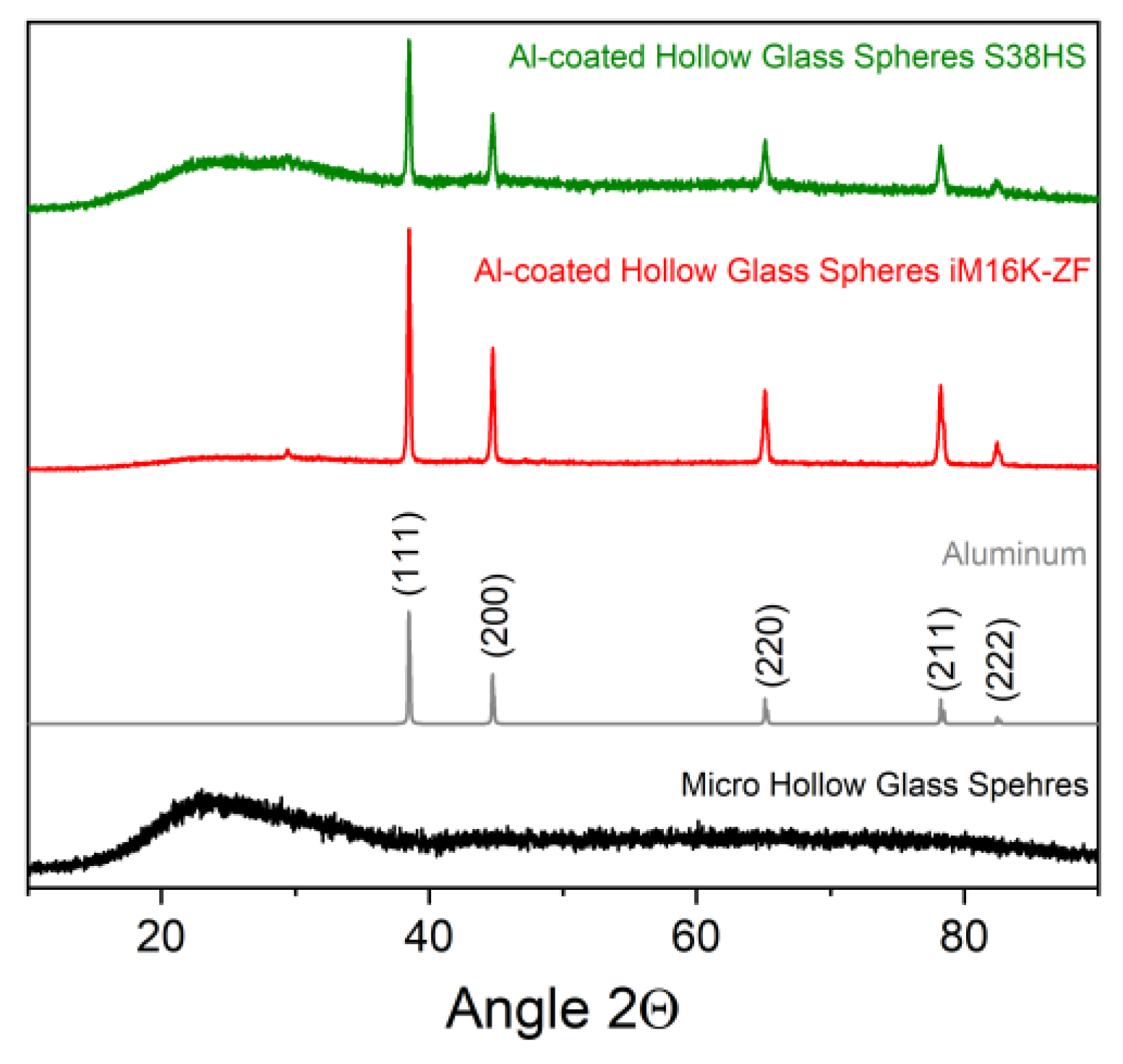
Figure 10.
SEM images of the untreated ((a,c) and post-treated (Turbula® Mixer; (b,d)) SMGS Type S (Experiment 2 A). Breaking off of the agglomerates and no change in surface morphology is evident.
Figure 10.
SEM images of the untreated ((a,c) and post-treated (Turbula® Mixer; (b,d)) SMGS Type S (Experiment 2 A). Breaking off of the agglomerates and no change in surface morphology is evident.

Figure 11.
SEM images of the post-treated (with magnetic stir bar, after 12 h) SMGS Type S (Experiment 2 A). Partially, a significant change in morphology takes place.
Figure 11.
SEM images of the post-treated (with magnetic stir bar, after 12 h) SMGS Type S (Experiment 2 A). Partially, a significant change in morphology takes place.
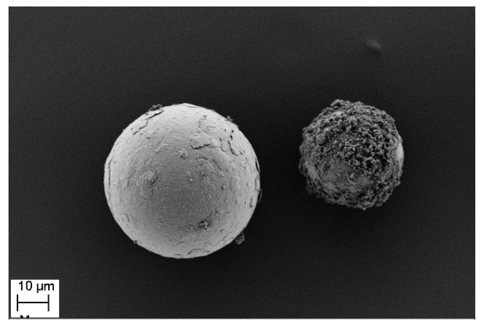
Figure 12.
SEM images of the post-treated (furnace) SMGS Type S (Experiment 2 A). No significant change in surface morphology at a temperature of 400 °C (a) and 500 °C (b) is apparent. For a temperature of 750 °C (c,d) a more inhomogeneous surface occurs due to the recrystallization of aluminum.
Figure 12.
SEM images of the post-treated (furnace) SMGS Type S (Experiment 2 A). No significant change in surface morphology at a temperature of 400 °C (a) and 500 °C (b) is apparent. For a temperature of 750 °C (c,d) a more inhomogeneous surface occurs due to the recrystallization of aluminum.

Figure 13.
Reflectance behavior of the adhesive strip, the original spheres and the pre-conditioned spheres in the wavelength range of 1.6 to 25 µm. Less or no influence of the adhesive strip and pre-conditioning in the wavelength range of interest (10 to 18 µm) is assumed.
Figure 13.
Reflectance behavior of the adhesive strip, the original spheres and the pre-conditioned spheres in the wavelength range of 1.6 to 25 µm. Less or no influence of the adhesive strip and pre-conditioning in the wavelength range of interest (10 to 18 µm) is assumed.

Figure 14.
Results of the reflection measurements of the PVD-coated MGS (reference spheres, (a): iM16K-ZF, (b): S38HS, (c): Type S) as well as the reflection at a wavelength of 15 µm of each sphere types plotted over the layer thickness (d). An increased reflection with increasing layer thickness can be observed.

Figure 15.
(a): Results of the reflection measurements of the LPD-coated Type S spheres (Experiment 1) with different coating times. Reflection increases with increasing coating time. (b): Comparison of the reflectance of LPD-coated (Experiment 1 A, 240 min) and PVD-coated (36 nm) spheres of Type S.

Figure 16.
(a): Results of the reflection measurements of the LPD-coated SMGS (Experiment 2 A) with an amount of 10 g. No increase in reflectance occurs. (b): Results of the reflection measurements of the LPD-coated MHGS (Experiment 2 B) with a volume of 6.5 mL. Further, no increase in reflection occurs.

Figure 17.
Measured reflectance of the post treated MGS from Experiment 2 A and 2 B, (a,b): Furnace treatment; (c): Turbula® Mixer, and (d): Stir bar treatment, an increase in reflection can be determined for all three post-treatments.
Figure 17.
Measured reflectance of the post treated MGS from Experiment 2 A and 2 B, (a,b): Furnace treatment; (c): Turbula® Mixer, and (d): Stir bar treatment, an increase in reflection can be determined for all three post-treatments.


Table 1.
Relevant properties of the examined Micro Solid Glass Spheres (SMGS) and Micro Hollow Glass Spheres (MHGS).
Table 1.
Relevant properties of the examined Micro Solid Glass Spheres (SMGS) and Micro Hollow Glass Spheres (MHGS).
| iM16K-ZF * | S38HS | Type S | |
|---|---|---|---|
| Supplier | 3M/Dyneon | SiLi | |
| Composition | soda-lime-borosilicate glass | soda lime glass | |
| Sphere type | hollow | solid | |
| Density [g/cm3] | 0.46 | 0.38 | 2.50 |
| D 50 [µm] ** | 20 | 45 | 40–70 |
| Compressive strength [MPa] | 110 | 38.5 | 250–300 *** |
| Anti-agglomeration agent | No | Yes | unspecified |
* laboratory product, not commercially available; ** median of particle size, 50 % of the particles are smaller than the declared value; *** according to the supplier.
Table 2.
Coating parameters of the aluminum coated glass spheres via Physical Vapor Deposition (PVD) at the University of Vienna.
Table 2.
Coating parameters of the aluminum coated glass spheres via Physical Vapor Deposition (PVD) at the University of Vienna.
| iM16K-ZF | S38HS | Type S | |
|---|---|---|---|
| Coating volume [l] | 1 | 1 | 0.1 |
| Coating time [h] | 4, 8, 12 | 8, 16, 21 | 1, 2, 4 |
| Corresponding layer thickness [nm] | 4, 12, 19 | 12, 29, 34 | 8, 19, 36 |
Table 3.
Parameters of the individual coating experiments.
| Setup | Experiment | Type of Spheres | Amount of MGS | Reaction Time [min] | Pre-Conditioning | Post-Treatment |
|---|---|---|---|---|---|---|
| 1 (with stir bar) | 1 A | SMGS | 10 g | 120 240 300 | yes | no |
| 1B | MHGS | 6.5 mL | 240 | yes | no | |
| 2 (rotating flask) | 2 A | SMGS | 6.5 mL | 240 | yes | yes |
| 2 B | MHGS | 6.5 mL | yes |
© 2019 by the authors. Licensee MDPI, Basel, Switzerland. This article is an open access article distributed under the terms and conditions of the Creative Commons Attribution (CC BY) license (http://creativecommons.org/licenses/by/4.0/).
Share and Cite
MDPI and ACS Style
Schwinger, L.; Lehmann, S.; Zielbauer, L.; Scharfe, B.; Gerdes, T. Aluminum Coated Micro Glass Spheres to Increase the Infrared Reflectance. Coatings 2019, 9, 187. https://doi.org/10.3390/coatings9030187
AMA Style
Schwinger L, Lehmann S, Zielbauer L, Scharfe B, Gerdes T. Aluminum Coated Micro Glass Spheres to Increase the Infrared Reflectance. Coatings. 2019; 9(3):187. https://doi.org/10.3390/coatings9030187
Chicago/Turabian StyleSchwinger, Laura, Sebastian Lehmann, Lukas Zielbauer, Benedikt Scharfe, and Thorsten Gerdes. 2019. "Aluminum Coated Micro Glass Spheres to Increase the Infrared Reflectance" Coatings 9, no. 3: 187. https://doi.org/10.3390/coatings9030187
Note that from the first issue of 2016, this journal uses article numbers instead of page numbers. See further details here.