Improved Adhesion of TiAlSiN Nanocomposite Coatings on Cemented Carbide Substrate by Pre-Implantation

Department of Material Processing and Control Engineering, School of Mechanical Engineering and Automation, Beihang University, Beijing 100083, China
*
Author to whom correspondence should be addressed.
Coatings 2019, 9(3), 209; https://doi.org/10.3390/coatings9030209
Submission received: 17 February 2019
/
Revised: 13 March 2019
/
Accepted: 22 March 2019
/
Published: 25 March 2019
(This article belongs to the Special Issue Advanced Thin Films Deposited by Magnetron Sputtering)
Abstract
:TiAlSiN coatings were deposited on YT 15 cemented carbide substrate by reactive direct current magnetron sputtering (DCMS) in a Plasma Immersion Ion Implantation and Deposition (PIII&D) system. The pre-implantation step and the coating deposition were carried out in the same experimental facility. In this article the effects of pre-implantation of several different elements (N, C, and O) were investigated. The adhesion strength, hardness, micro-structure, element concentration, depth profile, and the formation of coatings after the PIII experiments were characterized by a wide variety of techniques such as Rockwell indentation, scratch test, nano-indentation measurement, X-ray diffraction, energy dispersive spectroscopy, and Auger electron spectroscopy. The results showed that the adhesive strength of TiAlSiN coatings was significantly improved on samples pre-implanted with N and O whereas only slightly improved with pre-implantation of C. Additionally, the microstructure and mechanical properties of the TiAlSiN coatings were also altered through pre-implantation. The improved adhesion could be explained by the grain refinement and surface energy enhancement of the substrate by pre-implantation.
1. Introduction
During the past decades, transition-metal nitride coatings, TiN, TiAlN, TiSiN, TiAlSiN, TiAlSiYN, and (TiZrNbTaHf)N in particular, have attracted increasing critical attention and become a research focus in the modern manufacturing industry due to their unique properties including exceeding hardness, resistance against high-temperature oxidation, low friction, and outstanding thermal stability [1,2,3]. However stronger adhesion of TiAlSiN coating on the cemented carbide surface is preferred so as to accomplish a more desirable performance in high speed cutting and dry machining. As is putatively known, the adhesive strength between film and substrate determines the applicability of the coating, and good adhesion can effectively be conducive to its performance and prolong the lifetime of the cutting tools.
The adhesion of films to the substrate has fundamental influences upon the applications of nano-composite coatings, and much effort has been devoted to improving the cohesion between coatings and substrate materials. Of the numerous methods, the employment of a transition layer or multilayer structure is quite common to increase the adhesive strength. For instance, through making use of cathodic arc evaporation Chen et al. [4] optimized TiAlSiN coated inserts by turning the coating structure into a TiAlN–TiAlSiN bilayer or TiAlN/TiAlSiN multilayer, which exceedingly enhanced the adhesive strength and toughness. Accordingly during the process of milling, the lifetime for TiAlSiN coated inserts increased by 156% and 172% respectively. Çalışkan’s experiments [5] indicated that the nanocomposite (nc)-TiAlSiN/TiSiN/TiAlN multilayered hard coating had almost 44% higher LC3 (LC3: the first exposure of the substrate in the scratch track resulting from wear) and longer lifetime than single layer TiN and TiAlN coatings. Sui et al. [6] synthesized TiAlN, TiAlSiN monolayer and TiAlN/TiAlSiN composite multilayer by magnetron sputtering, the experimental results pointed to the conclusion that TiAlN/TiAlSiN composite coating, with its relatively low hardness and columnar structure, could enhance the adhesion strength compared with TiAlSiN single layer. Although the application of transition layer and multilayer structure to TiAlSiN coating is effective in terms of deposit adhesion improvement, these methods call for further process adjustment or necessitate additional hardware, which consequently raises the manufacturing cost. Ion pretreatment by Plasma Immersion Ion Implantation (PIII) is found to be an alternative approach to improve film–substrate cohesion without transferring primary properties (e.g., high hardness, outstanding oxidation, and wear resistance) of the films or involving new equipment and processes. Numerous experiments have been carried out to pre-implant into various coatings noble gas ions (Ar+, Kr+, Xe+), metal ions (titanium, yttrium, molybdenum, tungsten) [7,8,9] and nonmetallic ions (carbon, nitrogen, oxygen) [10,11], which markedly ameliorate the mechanical properties and tribological behavior. According to Weng’s experiments [8], the pre-implantation of C+ and Ti2+ ions occasioned the critical load of TiN coating to increase from 60 to 70 and 78 N respectively. Flege et al. [11] explored the effects of several different gases (N2, O2, Ar, CO2, C2H4, and air) under various bias voltages and found that most of the pre-implantations could strengthen immensely the adhesion of diamond-like coatings (DLC) on copper substrates. The improvement of coating-substrate adhesion can mainly be attributed to surface cleaning and roughening, grain refinement, the changes in film structure, and the generation of chemical bonds between the coating atoms and their corresponding substrate [8,11].
In conclusion, the ions pre-implantation proves to be effective for adhesive strength improvement. Unfortunately, so far, related studies and academic resources concerning its influence upon adhesion of TiAlSiN coatings have been quite limited. Therefore, in this paper nanocomposite TiAlSiN coatings pre-implanted with diverse ions were deposited through a multi-functional deposition apparatus which included a plasma base ion implantation (PBII) system. The adhesive strength, microstructure, crystallinity, and the nano-hardness of these coatings were investigated in order to examine the effects of different pre-implanted elements.
2. Experimental Details
2.1. Pre-Implantation and Deposition
Cemented carbide (YT 15, chemical composition: WC-79 wt.%, TiC-15 wt.%, Co-6 wt.%) of 16 × 16 mm2 was used as substrate. All substrates were firstly mechanically polished to a mirror surface (surface roughness: Ra 200 nm), then ultrasonically cleaned in acetone and ethanol for 10 min at room temperature respectively. After flushing with ultrapure water and drying with clean air, the samples were cleaned by glow sputtering with Ar+ ions at 2.0 Pa pressure and −1000 V substrate bias voltage for 30 min to remove surface contaminants and native oxide.
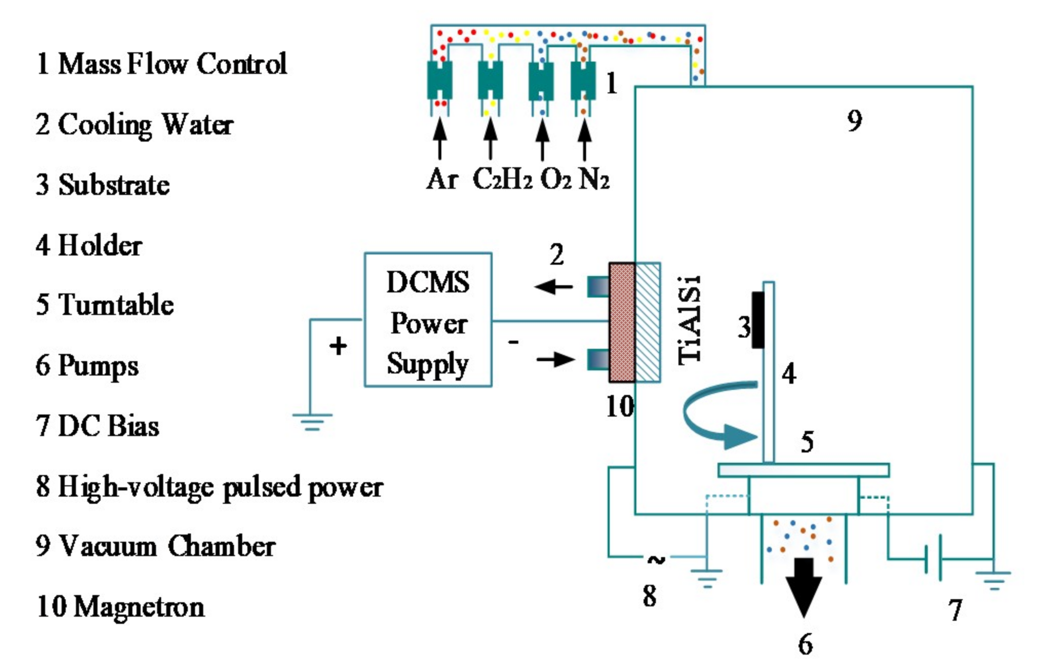
The processes of pre-implantation and deposition were accomplished with a base pressure of 5 × 10⁻³ Pa or lower in a multi-purpose plasma immersion ion implantation and deposition facility shown in Figure 1. These gases with a purity of 99.999%, namely, nitrogen (N2), ethyne (C2H2), and oxygen (O2) were fed into the chamber as implantation sources through several independent mass flow controls. The rectangular alloy targets Ti0.64Al0.3Si0.06 (12 × 10 cm2) were installed vertically on the vacuum chamber. The deposition of the TiAlSiN coatings was carried out in an atmosphere mixed with nitrogen and argon under a DC power of 900 W at a working pressure of 0.8 Pa. The deposition time was adjusted so as to have a coating thickness of around 2.0 μm. Four samples were used in this experiment: Sample 1 as the reference substrate was coated by TiAlSiN coating without pre-implantation, while Sample 2, 3, and 4 were pre-implanted with nitrogen ions (N+), carbon ions (C+), and oxygen ions (O+). Plasma Immersion Ion Implantation (PIII) was employed as the pre-treatment method, and the plasma was generated by glow discharge of the magnetron. Moreover, a substrate bias voltage was applied to the samples in order to extract the ions from the discharge and accelerate them toward the samples for implantation. During the sputtering the target-to-substrate distance was kept at 90 mm. Parameter details for pre-implantation and the deposition of TiAlSiN are respectively listed in Table 1 and Table 2.
2.2. Characterization
The adhesion of TiAlSiN coatings to cemented carbide substrate was evaluated qualitatively by the Rockwell indentation test and quantitatively by a scratch test [12,13,14]. The phase and crystalline structure were analyzed by X-ray diffraction (XRD, D/Max 2500, Rigaku, Tokyo, Japan) using Cu Kα radiation (Kγ = 1.5406 Å) in grazing-incidence mode (Grazing incidence angle: 1°) and the diffraction angles were scanned from 30° to 70°. The measurements of hardness (H) and elastic modulus (E) of the composite coatings were carried out by nano-indentation tester (Nano-Indentor G200, Agilent, Santa Clara, CA, USA) equipped with a Berkovich diamond indenter tip in the continuous stiffness measurement (CSM) mode. The load precision was 50 nN and the harmonic displacement was 2 nm. To acquire accurate hardness data, five independent indentation tests were conducted at random sites of each sample and in the calculation the maximum indentation depth was kept at no more than 10% of the thickness of the film [15]. The element contents were examined by an energy dispersive spectroscopy (EDS) detector (SEM-ZEISS-Gemini SEM 500, Oberkochen, Germany). The composition of TiAlSiN coatings and the implanted layer determined by Auger electron spectroscopy (AES, Perkin Elmer PHI 710, Perkin Elmer, Waltham, MA, USA) served as a function of time in order to evaluate the distribution range of the pre-implantation ions. AES operates under an ultra-high vacuum (4.3 × 10⁻⁶ Pa) during depth profiling, and the energy of the ions of the electron gun was 2 keV and of the ions of the argon sputtering 4 keV.
3. Results and Discussion
3.1. Microstructure of As-Deposited Coatings
Deposited under the same condition, the TiAlSiN coatings were uniformly 2 μm thick and the proportions of their elementary composition based on depth remained unchanged. The average element concentrations of coatings of all samples are listed in Table 3 while the element content of Samples 2–4 changed a little in comparison with Sample 1. The cause of this phenomenon is that after pre-implantation there are still some residual implanted elements in the deposited coatings [16,17]. Figure 2 depicts the XRD patterns of TiAlSiN coatings deposited by reactive direct current magnetron sputtering (DCMS) with N/C/O pre-implantation (Samples 2–4) and without pre-implantation (Sample 1). From Figure 2 it can be seen clearly that from each XRD spectrum there are three predominant diffraction peaks (111), (200), (220) corresponding to the B1 (NaCl-type) structure, the same as those observed in TiN or TiAlN. Another discovery equally claimed our attention in that there was no crystal diffraction peak corresponding to Si element. The reason for this phenomenon may be that Si can substitute Al/Ti at cation lattice sites of the B1-NaCl lattice when the concentration of Si is less than 5 at.%–6 at.% in TiSiN and TiAlSiN coatings, which was verified by other previous studies [18,19]. The XRD peak (200) of TiAlSiN coatings pre-implanted with N and O shifted slightly towards a higher angle, implying a decrease in the lattice parameter because of incorporation of other atoms whose radii were smaller than those of the existing atoms [20]; or possibly this shift may be attributed to lattice distortion caused by high energy particle (N+, O+, Ar+) bombardment. However, the glancing angle of the coating implanted with C displayed little change in comparison with that of the conventional TiAlSiN. As a result the incorporation of C atoms probably had little effect on the alternating grain size and lattice distortion. The reason lies in that C atoms already existed as WC in the cemented carbide. Meanwhile, there was a transformation from the preferred orientation of (111) peak to (200) orientation observed on XRD patterns. In previous research by Zheng et al. [21] the (111) preferred orientation was positively related to the intrinsic stress in the deposited coatings, so the decrease tendency of the (111) peak due to the pre-implantation of N/C/O atoms represented the decrease of residual stress in the coatings [22]. According to Shum’s investigation, the damage of TiN (111) lattice and the aggravation of disorder or the increase of amorphous phases [23], which were caused by the incorporation of N/C/O atoms, contributed to the weakening of the intensity of the (111) peak. In addition, the intensity sequence of the (200) peak was Sample 2, Sample 4, Sample 3, and Sample 1. According to Tsai’s survey [24], the intensity of the (200) peak is positively related with surface energy; as a result samples with pre-implantation have a different surface energy. Moreover, the change of the preferential orientation can be explained in terms of surface reactivity change after the implantation of different ions, which can also influence the surface energy. In this study, the increase of surface energy could be ascribed to the increase of the lattice dislocations and distortions in the cemented carbide substrate caused by the implantation of energetic particles [25], which subsequently refined the surface, raised the hardness, and provided more nucleation sites [8].
To assess the characteristics of nanocomposite TiAlSiN coatings the full width at half maximum (FWHM) values of the peak (111) and the grain size were estimated by the Debye–Scherrer formula [26]. The grain sizes of Samples 1–4 are 15.6, 13.5, 15.2, and 12.7 nm respectively, suggesting that the role played by pre-treatment of PBII in the crystal lattice size of the deposited coatings is quite insignificant. During the pre-implantation both the atoms merging into grain boundaries and the lattice distortion and dislocation caused by the bombardment of energetic particles could affect the grain size [27,28]. In this research, the defects resulting from bombardment of high-energy ions in the PBII process preventing grain boundary movement may constituted the chief factor in the decrease of the crystallite dimension.
3.2. Adhesion and Mechanical Properties of the Coatings
To evaluate the pre-implantation of N/C/O atoms on the film adhesion, the Rockwell (HRC) indentation test [29] with a 1470 N load was performed on the coatings and Figure 3 shows the optical micrographs of the indentations of Samples 1–4. In Figure 3a (S1) and Figure 3c (S3), a number of delaminations and spalls of the coating can be found around the margin of the indentations whereas little difference can be seen between the indentations of S1 and S4, indicating that the pre-implantation of C atoms has little influence on film-substrate adhesion. However, the amount of peeling and spalls of Sample 4 was much smaller. For Sample 2, there were few peelings or detachments except some slight cracks around the indentation margin, which showed that the pre-implantation of N or O atoms could greatly improve the adhesion of TiAlSiN, while the TiAlSiN coating with N per-implantation has the best adhesive strength.
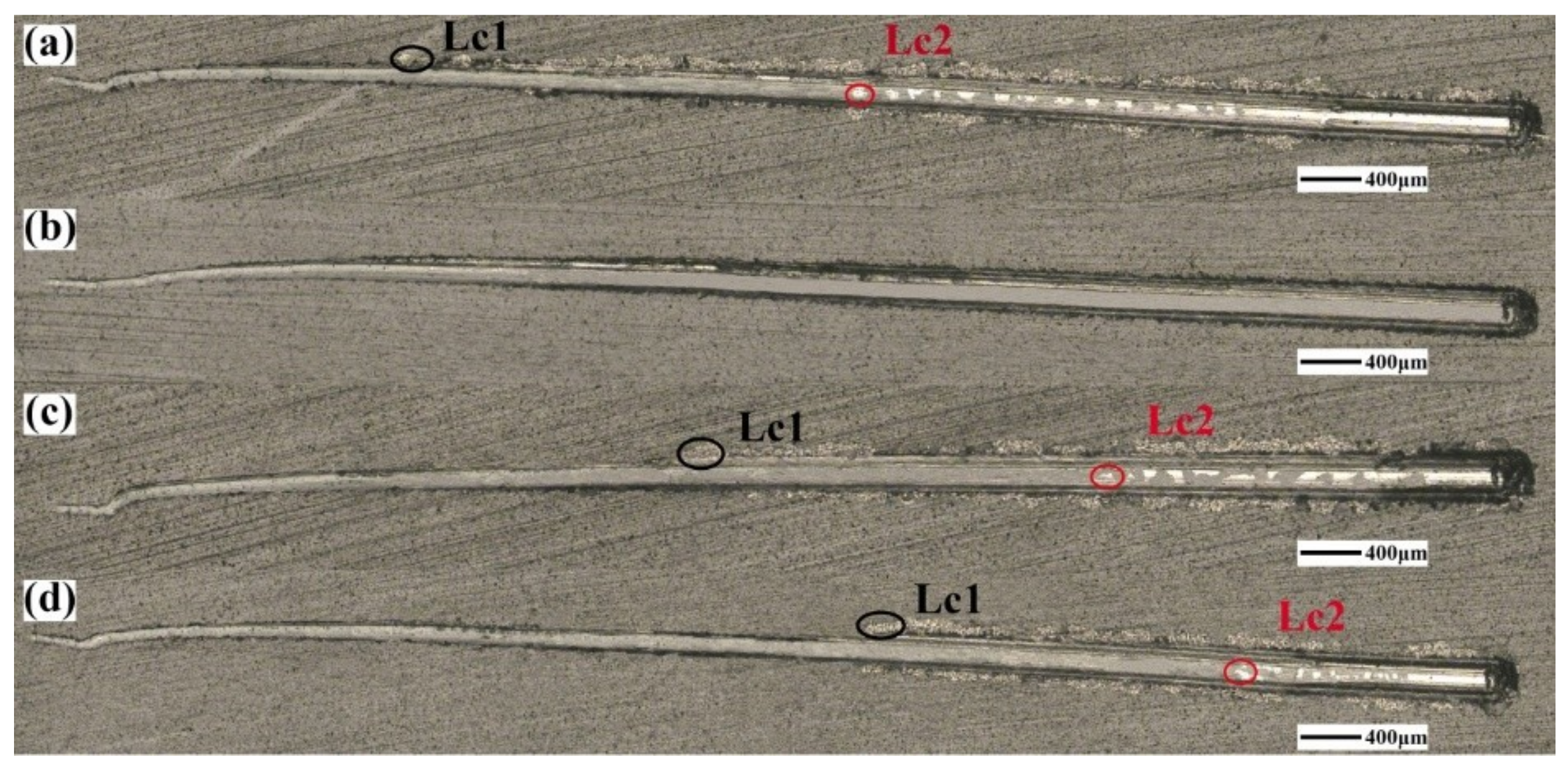
The scratch test was performed on samples to investigate more accurately the influences of pre-implantation of different elements upon adhesion. This test is usually applied to quantitatively evaluate the adhesion of hard coatings by means of obtainingthe critical loads of adhesion failure [30]. In terms of the adhesion in Table 4, LC1 is the critical load for the first cracks on the edge; as the critical load of the emergence of spalling, LC2 represents the actual adhesion [22]. Also, the maximum applied force in this test is 100 N. As is shown in Table 4, LC1 and LC2 of TiAlSiN coatings with pre-implantation increased to a varied extent compared with those without pre-treatment under the same deposition conditions. LC1 results of Samples 1–4 are 26, 100, 47, and 55 N and LC2 results of these samples are 56, 100, 69, and 78 N. Evidently TiAlSiN coating with N pre-implantation shows the best adhesion. Additionally, the optical images of the scratch tracks are presented in Figure 4, in which the detachment region of the pretreated samples is smaller than the none pretreated sample. The reason is that the pre-implantation process improves the load capacity of the films. Meanwhile the pre-implantation process prevents coatings from both fracture and plastic deformation, resulting in different microstructures with different preferential orientation. The change of fracture and plastic deformation of TiAlSiN coatings after N, C, and O ions implantation can be explained by this proposal: the difference in microstructure (preferential orientation, grain sizes), elemental composition, and the modification of the substrate/coating interface after pre-implantation [16]. This consequence convincingly substantiates the experimental results of the Rockwell indentation tests.
Table 4 also presents the hardness and E-modulus of Samples 1–4, in which the hardness values of Samples 1–4 are 22.56, 28.45, 23.18, and 26.72 GPa respectively. Values of elastic strain to failure (H/E) are also listed in Table 4 to determine the toughness and the wear resistance of the deposited coatings [31,32]. As can be seen, the coatings with pre-implantation show relatively higher nanohardness in comparison with those without pre-implantation coating, and the coating with pre-implantation of N displays the maximum hardness. This may be attributed to various factors, such as lattice constant, film structure, residual stress etc. [31]. In this targeted study, the reason for the increased hardness can be summarized as follows: (1).The decrease in grain size as computed by the well-known Debye–Scherrer formula [33] is in accordance with that of XRD. (2). The increased concentration of N/C/O atoms may cause the formation of Ti–N, Ti–C, and Ti–O bonds, which subsequently enhances the hardness of the substrate and forms an interface with better suitability to TiAlSiN coating of high hardness.
3.3. Auger Electron Spectroscopy Analysis
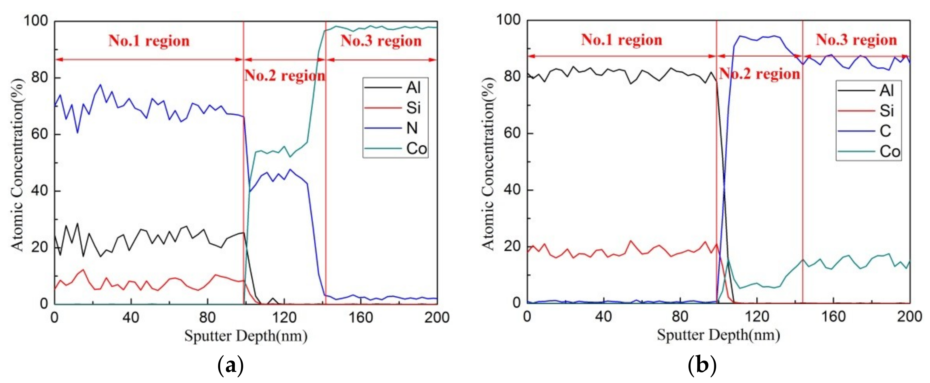
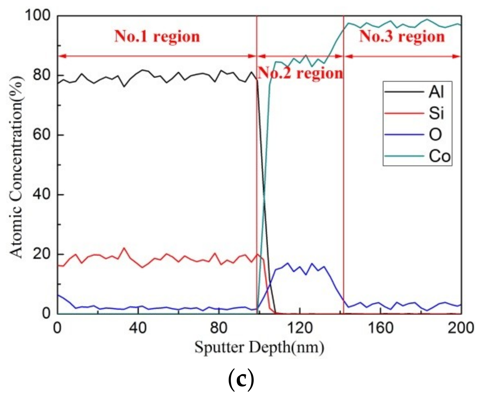
In order to analyze the influence of implantation upon elements composition in substrate and coating, the depth profiles of N, C and O concentration in the pre-implanted samples obtained by the Auger electron spectroscopy (AES) with 4 keV Ar+ ions are shown in Figure 5a–c in the form of atomic percentage. The depth profiles range from about 100 nm thickness of coatings to 200 nm depth of underlying substrates. The sputtering velocity of the measurement was 6 nm/min and the data were collected every half a minute. Take the coating with N pre-implanted in Figure 5a as an example. As is shown the coating is constituted of three regions. As the outmost layer, No.1 region is the deposited coating. In this region, the proportions of N, Al, Si and Co are about 70%, 25%, 5%, and approximately 0%, which coincide with our previous research [34]. In No.2 region located at the depth of about 100 nm, the proportions of N, Al, and Si are reduced rapidly to 45%, 0%, and 0% respectively while the proportion of Co increased to 55%, and the transition point where Co is detected can be assigned to the underlying cemented carbide substrate. No.3 region starts at a depth of about 140 nm, in which the evolution of the nitrogen element fell to a near zero value equivalent with the percentage of aluminum and silicon as in No.2 region while the proportion of cobalt increased to nearly 100%, reflecting the elements composition in the substrate. As a matter of fact the depth of No.3 region mirrors the maximum depth that the pre-implanted atoms could ever reach because its elemental composition is consistent with that in the cemented carbide substrate (YT 15). Likewise, the depth profiles of the samples with pre-implantation of carbon and oxygen also consist of three regions, namely, the region of deposited coating of which the depth ranges from 0 to 100 nm, the ion implantation area which is situated at a depth of 100–144 nm, and the substrate beyond the reach of implanted ions whose depth is more than 140 nm. Based on the concentration profiles of AES, it can be inferred that the implantation area is of a depth of approximately 0–35 nm from the surface of the substrate.
4. Conclusions
The experiments introduced in this paper indicate that the pre-implantation of N, C, O atoms enhances the adhesion and changes the microstructures of the TiAlSiN coatings as well as on the cemented carbide substrate (YT 15) in comparison with a non-implanted sample, while the degree of improvement for the adhesive strength depends heavily on the types of implanted ions. The pre-implantation of N or O atoms could greatly improve the adhesion of TiAlSiN coatings while the pre-implantation of C atoms has little influence on the coating–substrate adhesion. The laboratory examination tests such as Rockwell indentation and scratch test were carried out to present the adhesion of the coatings. At the same time the microstructure, hardness, depth profiles of films, and substrate were investigated. As was discovered, the improved adhesion on TiAlSiN films is primarily caused by the increased concentration of nitrogen, carbon, and oxygen in the substrate pre-implanted by N, C, and O ions, surface energy variations, as well as microstructure differences thanks to pre-implantation. Consequently, those variations lead to the changes of hardness and elastic modulus. These conclusions might provide better techniques for the protection of cutting tools in further investigations.
Author Contributions
Conceptualization, L.W. and Q.M.; Methodology, L.W. and L.L.; Software, L.W.; Validation, L.W., G.L. and Q.M.; Formal analysis, L.W.; Investigation, L.W.; Resources, L.W. and L.L.; Data Curation, L.W.; Writing—original draft preparation, L.W.; Writing—review and editing, L.W.; Visualization, L.W.; Supervision, L.W.; Project administration, L.W.; Funding acquisition, L.W.
Funding
This research was funded by National Nature Science Foundation of China, No. NSFC 11275020; National Science and Technology Major Project, No. 04: 2014ZX04012012; AVIC Technological Innovation Project, No. 2012E01138 and Fundamental Research Funds for the Central Universities, No. YWF-16-RSC-007.
Conflicts of Interest
The authors declare no conflict of interest.
References
- Bagdasaryan, A.A.; Pshyk, A.V.; Coy, L.E.; Konarski, P.; Misnik, M.; Ivashchenko, V.I.; Kempiński, M.; Mediukh, N.R.; Pogrebnjak, A.D.; Beresnev, V.M. A new type of (TiZrNbTaHf)N/MoN nanocomposite coating: Microstructure and properties depending on energy of incident ions. Compos. Part B Eng. 2018, 146, 132–144. [Google Scholar] [CrossRef]
- Pshyk, A.V.; Kravchenko, Y.; Coy, E.; Kempiński, M.; Iatsunskyi, I.; Załęski, K.; Pogrebnjak, A.D.; Jurga, S. Microstructure, phase composition and mechanical properties of novel nanocomposite (TiAlSiY)N and nano-scale (TiAlSiY)N/MoN multifunctional heterostructures. Surf. Coat. Technol. 2018, 350, 376–390. [Google Scholar] [CrossRef]
- Shypylenko, A.; Pshyk, A.V.; Medjanik, K.; Peplinska, B.; Oyoshid, K.; Jurga, S.; Coya, E. Influence of ion implantation on the physical and mechanical properties of multifunctional coatings based on Ti-Si-N. In Proceedings of the International Conference on Nanomaterials: Application & Properties, Atalanta, GA, USA, 15–20 September 2016. [Google Scholar]
- Chen, L.; Wang, S.Q.; Du, Y.; Zhou, S.Z.; Gang, T.; Fen, J.C.; Chang, K.K.; Li, Y.W.; Xiong, X.A. Machining performance of Ti-Al-Si-N coated inserts. Surf. Coat. Technol. 2010, 205, 582–586. [Google Scholar] [CrossRef]
- Çalışkan, H.; Kurbanoğlu, C.; Panjan, P.; Čekada, M.; Kramar, D. Wear behavior and cutting performance of nanostructured hard coatings on cemented carbide cutting tools in hard milling. Tribol. Int. 2013, 62, 215–222. [Google Scholar] [CrossRef]
- Sui, X.D.; Li, G.J.; Qin, X.S.; Yu, H.D.; Zhou, X.K.; Wang, K.; Wang, Q. Relationship of microstructure, mechanical properties and titanium cutting performance of TiAlN/TiAlSiN composite coated tool. Ceram. Int. 2016, 42, 7524–7532. [Google Scholar] [CrossRef]
- Rafaja, D. XRD characterization of ion-implanted TiN coatings. Surf. Coat. Technol. 1996, 86, 302–308. [Google Scholar] [CrossRef]
- Weng, K.W.; Chen, Y.C.; Lin, T.N.; Wang, D.Y. Characterization of titanium nitride coatings deposited by metal plasma ion pre-implantation and cathodic arc evaporation. J. Nanosci. Nanotechnol. 2009, 9, 1127–1132. [Google Scholar] [CrossRef]
- Narojczyk, J.; Werner, Z.; Barlak, M.; Morozow, D. The effect of Ti preimplantation on the properties of TiN coatings on HS 6-5-2 high-speed steel. Vacuum 2008, 83 (Suppl. 1), S228–S230. [Google Scholar] [CrossRef]
- Shum, P.W.; Xu, Y.F.; Zhou, Z.F.; Li, K.Y. Effects of carbon and nitrogen ion implantations on surface and tribological properties of Ti–Al–Si–N coatings. Surf. Eng. 2012, 28, 149–154. [Google Scholar] [CrossRef]
- Flege, S.; Hatada, R.; Ensinger, W.; Baba, K. Improved adhesion of DLC films on copper substrates by preimplantation. Surf. Coat. Technol. 2014, 256, 37–40. [Google Scholar] [CrossRef]
- Sekler, J.; Steinmann, P.A.; Hintermann, H.E. The scratch test: Different critical load determination techniques. Surf. Coat. Technol. 1988, 36, 519–529. [Google Scholar] [CrossRef]
- Valli, J.; Mäkelä, U. Applications of the scratch test method for coating adhesion assessment. Wear 1987, 115, 215–221. [Google Scholar] [CrossRef]
- Paschke, H.; Weber, M.; Kaestner, P.; Braeuer, G. Influence of different plasma nitriding treatments on the wear and crack behavior of forging tools evaluated by Rockwell indentation and scratch tests. Surf. Coat. Technol. 2010, 205, 1465–1469. [Google Scholar] [CrossRef]
- Roudet, F.; Chicot, D.; Decoopman, X.; Iost, A.; Bürgi, J.; Garcia-Molleja, J.; Nosei, L.; Feugeas, J. Modeling of very thin aluminum nitride film mechanical properties from nanoindentation measurements. Thin Solid Films 2015, 594, 129–137. [Google Scholar] [CrossRef]
- Shypylenko, A.; Pshyk, A.V.; Grześkowiak, B.; Medjanik, K.; Peplinska, B.; Oyoshi, K.; Pogrebnjak, A.; Jurga, S.; Coy, E. Effect of ion implantation on the physical and mechanical properties of Ti-Si-N multifunctional coatings for biomedical applications. Mater. Des. 2016, 110, 821–829. [Google Scholar] [CrossRef]
- Flege, S.; Hatada, R.; Vogel, T.; Bruder, E.; Major, M.; Ensinger, W.; Baba, K. Tightly adhering diamond-like carbon films on copper substrates by oxygen pre-implantation. Surf. Coat. Technol. 2018, 335, 134–139. [Google Scholar] [CrossRef]
- Pshyk, A.V.; Coy, L.E.; Nowaczyk, G.; Kempiński, M.; Peplińska, B.; Pogrebnjak, A.D.; Beresnev, V.M.; Jurga, S. High temperature behavior of functional TiAlBSiN nanocomposite coatings. Surf. Coat. Technol. 2016, 305, 49–61. [Google Scholar] [CrossRef] [Green Version]
- Wu, W.Y.; Su, A.; Liu, Y.; Yeh, C.M.; Chen, W.C.; Chang, C.L. Effect of DC input power and nitrogen ratio on the deposition of Ti1−xAlxN thin films using high power impulse magnetron sputtering technique. Surf. Coat. Technol. 2016, 303, 48–53. [Google Scholar] [CrossRef]
- Zhu, L.H.; Song, C.; Ni, W.Y.; Liu, Y.X. Effect of 10% Si addition on cathodic arc evaporated TiAlSiN coatings. Trans. Nonferrous Met. Soc. China 2016, 26, 1638–1646. [Google Scholar] [CrossRef]
- Zheng, Z.; Yu, Z. Characteristics and machining applications of Ti(Y)N coatings. Surf. Coat. Technol. 2010, 204, 4107–4113. [Google Scholar] [CrossRef]
- Du, H.; Xiong, J.; Zhao, H.; Wu, Y.; Wan, W.; Wang, L. Structure and properties of TiAlLaN films deposited at various bias voltages. Appl. Surf. Sci. 2014, 292, 688–694. [Google Scholar] [CrossRef]
- Shum, P.W.; Zhou, Z.F.; Li, K.Y. Friction and wear reduction of hard TiAlSiN coatings by an integrated approach of laser surface texturing and high-energy ion implantation. Surf. Coat. Technol. 2014, 259, 136–140. [Google Scholar] [CrossRef]
- Tsai, D.C.; Huang, Y.L.; Lin, S.R.; Liang, S.C.; Shieu, F.S. Effect of nitrogen flow ratios on the structure and mechanical properties of (TiVCrZrY)N coatings prepared by reactive magnetron sputtering. Appl. Surf. Sci. 2010, 257, 1361–1367. [Google Scholar] [CrossRef]
- Chen, J.S.; Sun, Z.; Guo, P.S.; Zhang, Z.B.; Xu, H.J. Effect of ion implantation on surface energy of ultrahigh molecular weight polyethylene. J. Appl. Phys. 2003, 93, 5103–5108. [Google Scholar] [CrossRef]
- Kumar, S.S.; Sharma, A.; Rao, G.M.; Suwas, S. Investigations on the effect of substrate temperature on the properties of reactively sputtered zirconium carbide thin films. J. Alloy. Compd. 2017, 695, 1020–1028. [Google Scholar] [CrossRef]
- Shum, P.W.; Xu, Y.F.; Zhou, Z.F.; Cheng, W.L.; Li, K.Y. Study of TiAlSiN coatings post-treated with N and C + N ion implantations. Part 2: The tribological analysis. Wear 2012, 274–275, 274–280. [Google Scholar] [CrossRef]
- Lee, J.W.; Tien, S.K.; Kuo, Y.C. The effects of pulse frequency and substrate bias to the mechanical properties of CrN coatings deposited by pulsed DC magnetron sputtering. Thin Solid Films 2006, 494, 161–167. [Google Scholar] [CrossRef]
- Ma, Q.; Li, L.; Ye, X.; Gu, J.; Lei, W.; Yi, X. Effect of bias voltage on TiAlSiN nanocomposite coatings deposited by HiPIMS. Appl. Surf. Sci. 2016, 392, 826–833. [Google Scholar] [CrossRef]
- Gerth, J.; Wiklund, U. The influence of metallic interlayers on the adhesion of PVD TiN coatings on high-speed steel. Wear 2008, 264, 885–892. [Google Scholar] [CrossRef]
- Lv, Y.; Li, J.; Liu, X.; Li, H.; Zhou, H.; Chen, J. Influence of substrate bias voltage on structure and properties of the CrAlN films deposited by unbalanced magnetron sputtering. Appl. Surf. Sci. 2012, 258, 3864–3870. [Google Scholar] [CrossRef]
- Wang, L.; Li, L.; Kuang, X. Effect of substrate bias on microstructure and mechanical properties of WC-DLC coatings deposited by HiPIMS. Surf. Coat. Technol. 2018, 352, 33–41. [Google Scholar] [CrossRef]
- Holzwarth, U.; Gibson, N. The Scherrer equation versus the ‘Debye-Scherrer equation’. Nat. Nanotechnol. 2011, 6, 534. [Google Scholar] [CrossRef] [PubMed]
- Ma, Q.S.; Li, L.H.; Xu, Y.; Ma, X.; Xu, Y.; Liu, H.T. Effect of Ti content on the microstructure and mechanical properties of TiAlSiN nanocomposite coatings. Int. J. Refract. Met. Hard Mater. 2016, 59, 114–120. [Google Scholar] [CrossRef]
Figure 1.
Schematic diagram of the multi-purpose plasma immersion ion implantation and deposition facility.
Figure 1.
Schematic diagram of the multi-purpose plasma immersion ion implantation and deposition facility.

Figure 2.
XRD patterns of TiAlSiN coatings with N/C/O pre-implantation and without pre-implantation.
Figure 2.
XRD patterns of TiAlSiN coatings with N/C/O pre-implantation and without pre-implantation.
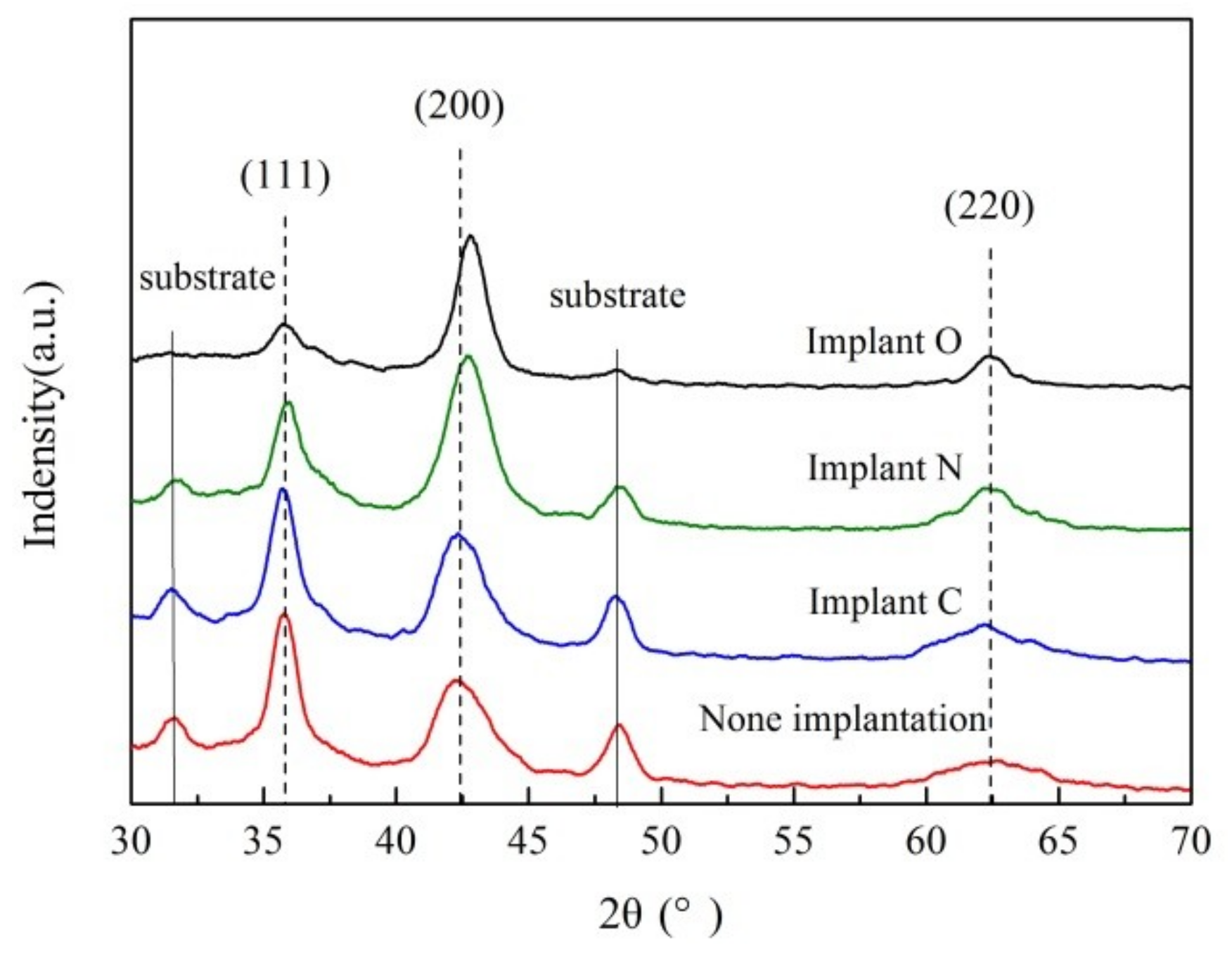
Figure 3.
Rockwell indentation tests with a load of 1470 N of TiAlSiN coatings deposited on YT 15 cemented carbide substrate. (a) without pre-implantation (b) pre-implantation of N (c) pre-implantation of C (d) pre-implantation of O.
Figure 3.
Rockwell indentation tests with a load of 1470 N of TiAlSiN coatings deposited on YT 15 cemented carbide substrate. (a) without pre-implantation (b) pre-implantation of N (c) pre-implantation of C (d) pre-implantation of O.
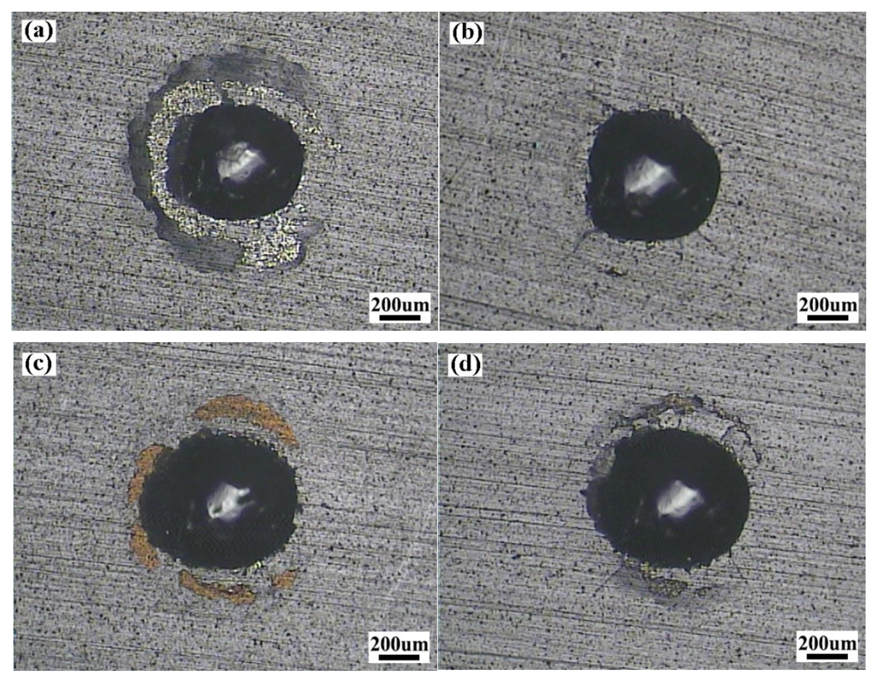
Figure 4.
Optical images of scratch tests of TiAlSiN coatings (a) without pre-implantation (b–d) pre-implantation of N/C/O.
Figure 4.
Optical images of scratch tests of TiAlSiN coatings (a) without pre-implantation (b–d) pre-implantation of N/C/O.

Figure 5.
AES depth profiles of TiAlSiN coatings deposited on the pretreated cemented carbide substrate (a) pre-implantation of N (b) pre-implantation of C (c) pre-implantation of O.
Figure 5.
AES depth profiles of TiAlSiN coatings deposited on the pretreated cemented carbide substrate (a) pre-implantation of N (b) pre-implantation of C (c) pre-implantation of O.

Table 1.
Details of pre-implantation parameters.
| Implantation Stage | Substrate Bias (V) | Temperature (°C) | Pressure (Pa) | Implantation Time (min) |
|---|---|---|---|---|
| Stage I | −10,000 (pulse) | 150 | 1 | 8 |
| Stage II | −8000 (pulse) | 150 | 1 | 5 |
| Stage III | −1600 (DC) | 150 | 1 | 5 |
| Stage IV | −1200 (DC) | 150 | 1 | 5 |
Table 2.
Details of coating deposition parameters.
| Target-Substrate Distance (cm) | Substrate Bias (V) | Temperature (°C) | PN2/PAr | Working Pressure (Pa) | Target Current (A) | Sputtering Power (W) |
|---|---|---|---|---|---|---|
| 9 | −100 | 150 | 1/3 | 0.8 | 2 | 900 |
Table 3.
Element concentration of TiAlSiN coatings.
| Sample Number | Sample 1 | Sample 2 | Sample 3 | Sample 4 | |
|---|---|---|---|---|---|
| Element of Pre-Implantation | None | Nitrogen (N) | Carbon (C) | Oxygen (O) | |
| Element Concentration (at.%) | Ti | 33.48 ± 0.35 | 32.89 ± 0.28 | 33.97 ± 0.40 | 33.16 ± 0.38 |
| Al | 16.32 ± 0.25 | 15.94 ± 0.33 | 16.04 ± 0.18 | 16.49 ± 0.22 | |
| Si | 3.60 ± 0.05 | 3.54 ± 0.08 | 3.78 ± 0.11 | 3.39 ± 0.06 | |
| N | 46.60 ± 0.43 | 47.63 ± 0.52 | 45.57 ± 0.62 | 46.11 ± 0.36 | |
| C | 0 | 0 | 0.64 ± 0.05 | 0 | |
| O | 0 | 0 | 0 | 0.85 ± 0.03 | |
Table 4.
Results of the adhesion experiments corresponding to the hardness and elastic modulus.
| Samples | Pre-Implantation | Adhesion | Hardness (GPa) | Elastic Modulus (GPa) | H/E | ||
|---|---|---|---|---|---|---|---|
| Rockwell | LC1 (N) | LC2 (N) | |||||
| Sample 1 | None | HF3 | 26 | 56 | 22.6 ± 2.3 | 402.8 ± 8.5 | 0.056 |
| Sample 2 | Nitrogen (N) | HF1 | 100 | 100 | 28.5 ± 3.1 | 466.4 ± 9.2 | 0.061 |
| Sample 3 | Carbon (C) | HF3 | 47 | 69 | 23.2 ± 2.1 | 399.7 ± 8.7 | 0.058 |
| Sample 4 | Oxygen (O) | HF2 | 55 | 78 | 26.7 ± 2.9 | 468.8 ± 9.1 | 0.057 |
© 2019 by the authors. Licensee MDPI, Basel, Switzerland. This article is an open access article distributed under the terms and conditions of the Creative Commons Attribution (CC BY) license (http://creativecommons.org/licenses/by/4.0/).
Share and Cite
MDPI and ACS Style
Wang, L.; Li, L.; Li, G.; Ma, Q. Improved Adhesion of TiAlSiN Nanocomposite Coatings on Cemented Carbide Substrate by Pre-Implantation. Coatings 2019, 9, 209. https://doi.org/10.3390/coatings9030209
AMA Style
Wang L, Li L, Li G, Ma Q. Improved Adhesion of TiAlSiN Nanocomposite Coatings on Cemented Carbide Substrate by Pre-Implantation. Coatings. 2019; 9(3):209. https://doi.org/10.3390/coatings9030209
Chicago/Turabian StyleWang, Lei, Liuhe Li, Guodong Li, and Quansheng Ma. 2019. "Improved Adhesion of TiAlSiN Nanocomposite Coatings on Cemented Carbide Substrate by Pre-Implantation" Coatings 9, no. 3: 209. https://doi.org/10.3390/coatings9030209
Note that from the first issue of 2016, this journal uses article numbers instead of page numbers. See further details here.