The Evaluation of Durability of Plasma-Sprayed Thermal Barrier Coatings with Double-layer Bond Coat

School of Materials Science and Engineering, Xi’an Shiyou University, Xi’an 710065, China
*
Author to whom correspondence should be addressed.
Coatings 2019, 9(4), 241; https://doi.org/10.3390/coatings9040241
Submission received: 15 March 2019
/
Revised: 8 April 2019
/
Accepted: 9 April 2019
/
Published: 9 April 2019
(This article belongs to the Special Issue From Metallic Coatings to Additive Manufacturing)
Abstract
:The durability of atmospheric plasma-sprayed thermal barrier coatings (APS TBCs) with a double-layer bond coat was evaluated via isothermal cycling tests under 1120 °C. The bond coat consisted of a porosity layer deposited on the substrate and an oxidation layer deposited on the porosity layer. Two types of double-layer bond coats with different thickness ratios of the porosity layer to the oxidation layer (type A: 1:2 and type B: 2:1, respectively) were prepared. The results show that the porosity layer was oxidation free, the oxidation layer included a fraction of well-distributed α-Al2O3. The coefficient of thermal expansion of the oxidation layer was about 11.2 × 10⁻⁶ K−1, which was rather lower than that of the porosity layer. Thus, the oxidation layer can be regards as a secondary bond coat between ceramic topcoat and traditional bond coat. The thermal cyclic lifetime of type A TBCs was about 60 cycles, which exceeded 1.2 times the durability of type B TBCs. The delamination cracks in both TBCs all propagated in the ceramic topcoat, which were all identical to those in traditional TBCs. Therefore, the design of the double-layer bond coat affected the stress level rather than the stress distribution in TBCs.
1. Introduction
Thermal barrier coatings (TBCs) are normally used in aircraft engines and power generation gas turbines to protect the turbine components from high-temperature erosion and to improve the efficiency of facilities [1,2,3]. Thermal barrier coatings are typically composed of a ceramic topcoat, alloy bond coat (BC), thermally grown oxide (TGO), and superalloy substrate, individually [4].
The spallation of the ceramic topcoat, typically made of yttria-stabilized zirconia (YSZ), is one of the factors that hinders the service of TBCs. The failure of atmospheric plasma-sprayed (APS) TBCs can be affected by many factors, such as TGO growth [1,2,4,5,6,7,8], thermal expansion mismatch [1,8,9,10], YSZ sintering [11,12,13,14,15], the temperature gradient across YSZ coating [16,17,18,19] and the profile of the bond coat surface [7,20,21,22,23], etc. Thermal expansion mismatch between the YSZ coating and the substrate is one of the most critical factors that presently affects the durability of TBCs [9,10,19,24,25]. It has been well documented that the in-plane stress induced by thermal expansion mismatch, σ, is directly proportional to the difference in the coefficient of thermal expansion (Δα) between the YSZ coating and the substrate, and the energy release rate of TBCs is proportional to (Δα)2. In addition, our previous report indicated that the energy release rate is roughly linear to the durability of TBCs [19]. Therefore, the durability of TBCs increase if the difference in the coefficient of thermal expansion between the substrate and the YSZ coating decreases. The methods for alleviating the thermal expansion mismatch can be summarized into two types in the term of the microstructure of TBCs: changing the composition or microstructure of the ceramic layer and changing the composition or microstructure of the bond coat. It has been reported that improving strain tolerance of the ceramic topcoat via the microstructure and composition can dramatically improve the durability of TBCs. Presently, the typical microstructure of the YSZ coating that experts focus on are quasi-columnar YSZ coatings prepared by plasma-sprayed physical-vapor deposition (PS-PVD) [26,27,28,29,30] or suspension plasma spraying (SPS) [31,32]; columnar YSZ coating deposited by electron-beam physical-vapor deposition (EB-PVD) [33,34,35]; segmentation cracks in ceramic topcoat [36,37], the double-layer structure of ceramic coatings [38], and self-enhancing ceramic coating [39].
The antioxidant capacity of the bond coat can be improved via the composition or microstructure of the bond coat [40,41,42,43], such as controlling the interface between the splats in the coating [43], a double-layer structure [44], and a column-like microstructure [45]. Gong [44] indicated that a double-layer MCrAlY (M = Ni, Co or Ni + Co) bond coat can provide excellent functions for both oxidation resistance and diffusion resistance, hence improves the durability of TBCs. Cao [46] pointed out that the scale adherence strength in double-layer bond coat system is higher than that in traditional bond coat systems. These reports deposited double-layer bond coat are all focused on improving the oxidation resistance of bond coat, yet in absence of consideration about thermal expansion mismatch of these two layers. However, it has been well documented that the thermal expansion behavior of the material is strongly related to its microstructure [47,48]. Therefore, the mismatch of the thermal expansion may be alleviated via controlling the microstructure of the bond coat. Jiang [24] designed a double-layer bond coat with different porosities: a dense layer deposited on the substrate and a porosity layer with macro voids neighboring the YSZ coating. It indicated that the porosity layer seriously internally oxidizes and rapidly swells after isothermal exposure, and the thermal expansion mismatch between the topcoat and substrate alleviates much limitedly. This layer swelling accelerates the failure of the TBCs due to the enormous residual stress induced by the roughness change at the interface. Therefore, the macro voids in the bond coat which closes to the ceramic topcoat deteriorates its oxidation resistance and has no positive role on the durability of TBCs in terms of alleviation of thermal expansion mismatch.
On the other hand, the thermal expansion mismatch can be alleviated if the dimensions of the voids decrease and are replaced by fine α-Al2O3. Therefore, a double-layer bond coat with gradient thermal expansion coefficients is fabricated. Indeed, this double-layer bond coat is benefit form relieving the stress induced by the thermal expansion mismatch in TBCs. However, how the double-layer bond coat with gradient thermal expansion coefficients affects the durability and the cracking mode of TBCs is still not clear. Therefore, in the present paper, the double-layer bond coat with gradient thermal expansion coefficients were developed. Furthermore, the durability and cracking mode of this type of TBC were evaluated via thermal cycling tests. The bond coats in this case included a porosity layer deposited on the substrate and an oxidation layer, with well-distributed α-Al2O3 neighboring the YSZ coating.
2. Experimental
2.1. Materials and Coating Deposition Methods
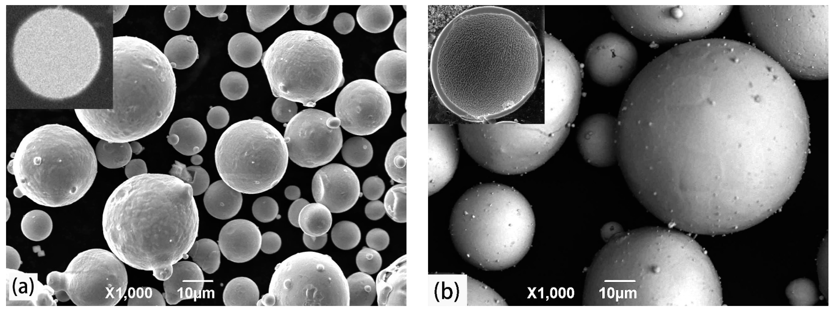
Inconel 738 (Φ 25.4 mm × 3 mm, Beijing Cisri-Gaona Materials & Technology Co., Ltd., Beijing, China) was used as a substrate. The commercial powder Co–32Ni–21Cr–8Al–0.5Y (wt.%) (Amdry 9951, Metco, Westbury, NY, USA) with a solid spherical shape for a bond coat was used, as shown in Figure 1a. Hollow spherical 8 wt.% yttria-stabilized zirconia powder (8YSZ) (204B-NS, −75, +45 μm, Metco, Westbury, NY, USA) was selected to deposit the ceramic topcoat, as shown in Figure 1b.
The structure of the TBC in this case is identical to traditional APS TBCs, including four layers, while the bond coat in this case consists of two layers: a porosity layer deposited on the substrate and an oxidation layer with dispersedly distributed α-Al2O3 neighboring the YSZ coating. To keep the oxidation degree of particles, shrouded plasma spraying (GP-80, Jiujiang Plasma Spraying Factory, Jiujiang, Jiangxi, China) was employed to deposit the porosity layer on the substrate. The plasma parameters are shown in Table 1. The argon included <10 ppm of oxygen used as the shielding gas atmosphere during the shrouded plasma spraying. The oxidation layer was deposited on the porosity layer via high-velocity oxygen fuel spraying (HVOF, JP-8000, Praxair, Danbury, CT, USA); the spray conditions are shown in Table 2. The whole thickness of the bond coat was about 180 μm. Two types of bond coats with different thickness ratios of the porosity layer to oxidation layer were prepared. The thickness ratios of the porosity layer to oxidation layer were 1:2 (type A) and 2:1 (type B), respectively. Atmospheric plasma spraying (APS) was employed to deposit an approximately 200 μm YSZ topcoat using an Ar–H2 plasma jet. The power of APS was 39 kW, other parameters were as same as the shrouded plasma-spraying parameters, as shown in Table 1.
2.2. Pretreatment and Thermal Cycling Tests for TBCs
The previous study indicated that α-Al2O3 can form easily at 1000 °C and the Al element located in the bottom can diffuse to the YSZ/TGO interface effectively at 1080 °C [49]. Thus, to remedy the discontinuity of α-Al2O3 generated during thermal spraying, the heat treatment of the specimens was carried out in an argon atmosphere at 1000 °C for 4 h and then 1080 °C for 4 h. After that, a continuous and fully covered α-Al2O3 formed on the surface of the oxidation layer. To examine the oxidation resistance of the oxidation layer, the samples were further isothermal-oxidized at 1000 °C for 200 h.
The durability of the TBCs was evaluated via isothermal shock test after pre-treating in an argon atmosphere. The temperature of the thermal cycling tests was 1120 °C. One whole thermal cycling test was 30 min, including 26 min of holding time, and 4 min of cooling time. The temperature can be cooled down to about 100 °C through an air blower in 4 min. The failure of the TBCs was defined as 50% of the YSZ coating delaminated and/or spalled. The durability of TBCs was an average of the five specimens.
The cross-sections for the scanning electron microscope (SEM) were prepared following the procedure in American Society for Testing Materials (ASTM) B748 [50]. To avoid damage to the microstructures of the samples, the samples were mounted with epoxy adhesive by vacuum infiltration. Then abrasive papers of different types were employed to grind the samples successively. After that, polishing was finished with a 0.5 μm diamond on micro-cloth. Scanning electron microscopy (SEM, JSM-6390A, JEOL, Tokyo, Japan) equipped with an energy dispersive spectrometer (EDS) was employed to characterize the microstructure of the TBCs. All images were photographed in the backscattered electron image mode.
3. Results and Discussion
3.1. Microstructure of As-Sprayed TBCs
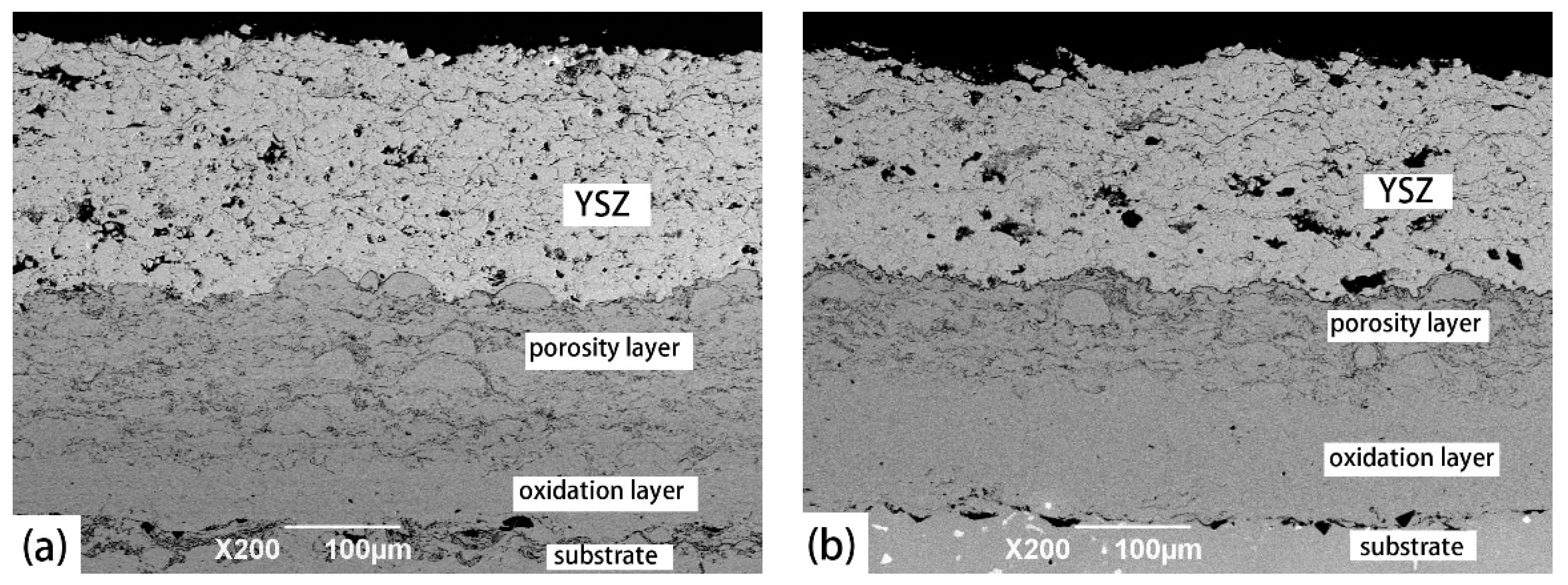
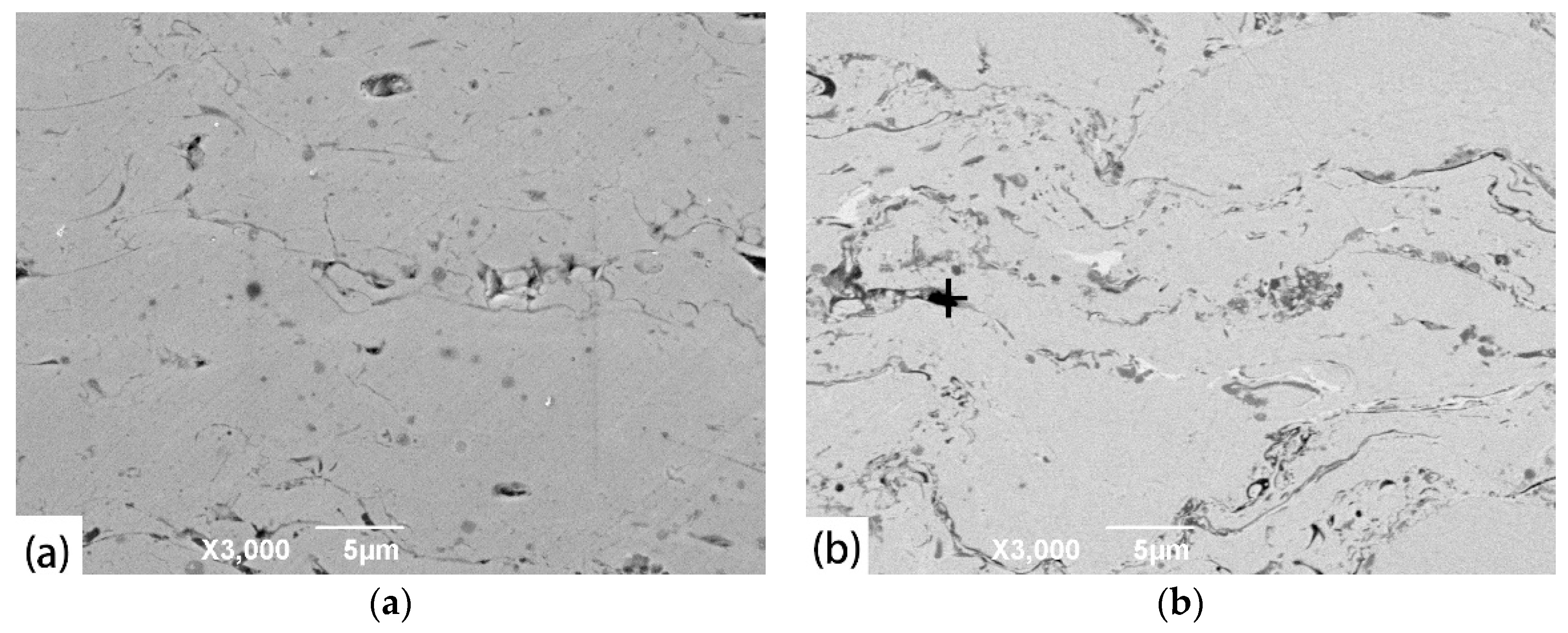
Figure 2 shows the microstructures of the as-deposited TBCs with the different thickness ratios of the porosity layer to oxidation layer. Two types of samples were produced in this case: the thicknesses of the porosity layer and oxidation layer in the type A sample were 60 and 120 μm, and those in the type B sample were 120 and 60 μm, respectively. Figure 3 shows the cross-sections of the porosity layer and oxidation layer in the type A samples. The spray parameters of each layer in this study were the same in sample A and sample B. The microstructures of the porosity layer and oxidation layer in sample B were considered to be identical to those of sample A. Thus, the microstructural characteristics of only sample A is represented in Figure 3, avoiding the repeated description. The porosity layers in both sample types presented typical lamellar structures and also included some un-melted particles, which is similar to that of APS YSZ coating [51], as shown in Figure 3a. This layer may provide a higher capacity that alleviates to a greater degree the thermal expansion misfit between YSZ coating and the substrate than a dense bond coat because the particles in this layer can expand and contract rather freely, and expansion and contraction from the substrate to the YSZ coating can be more efficiently alleviated. Additionally, the porosity layer was nearly oxidation free because of the shielding argon atmosphere. In comparison, oxides are inevitable in traditional APS bond coats. [51,52]. Thus, in this case, compared with traditional APS bond coats, the depletion period of Al in the porosity layers was extended.
The oxidation layer exhibited a dense microstructure with some oxides, as shown in Figure 3b. The oxides were rather dispersedly distributed in the oxidation layer. EDS results showed that internal oxides were principally composed of α-Al2O3, as shown in Figure 3c. This means that a fraction of the particles was oxidized during the deposition of the oxidation layer. The α-Al2O3 generated on the surface of the bond coat are generally an expected oxide [53,54]. The generation of Al2O3 on the inside of the bond coat indicated that a fraction of the Al element in the spray powder was consumed. It may lead to the Al shortage in the oxidation layer during the thermal cycling tests. Thus, the high-temperature oxidation behavior of TBCs in this case was examined in a furnace for 200 h at a temperature of 1000 °C. The morphologies in the oxidation layer are shown in Figure 4. The results show that the Al-rich phase (NiAl) existed in these two oxidation layers. Thus, compared with traditional bond coat, the premature depletion of Al in this bond coat can be neglected. Compared with previous report [24], the internal oxides of α-Al2O3 particles in this case were fairly fine and uniform and there were no significant microflaws in the bond coat. The coefficient of thermal expansion of α-Al2O3 was much lower than other three layers in the TBCs. Correspondingly, this well-distributed α-Al2O3 can decrease the coefficient of thermal expansion of as-sprayed oxidation layers. The thermal expansion coefficient of these two layers can be calculated via the following equation, respectively [55].
where α is the coefficient of thermal expansion of the porosity layer and oxidation layer/10−6 K−1, αm and αp are the thermal expansion coefficient of the matrix and particles/10−6 K−1; Km and Kp are the bulk modulus of the matrix and particles/GPa; Vm and Vp are the volume fraction of the matrix and particles/%. The coefficient of thermal expansion of the oxidation layer was calculated with consideration of the α-Al2O3. The coefficient of thermal expansion of the porosity layer was calculated in the absence of the consideration of α-Al2O3 because of the much more limited oxidation. The results show that the thermal expansion coefficient of the porosity layer was approximately 11.8 × 10⁻⁶ K−1 and that of oxidation layer was about 11.2 × 10⁻⁶ K−1. Therefore, the double-layer bond coat designed in this case had a gradient thermal expansion coefficient. The oxidation layer can be considered as a second bond coat between the YSZ coating and the traditional bond coat. This layer can further alleviate stress induced by the thermal expansion mismatch in TBCs as expected.
3.2. Thermal Cyclic Lifetime of TBCs
The thermal cycling lifetimes of these two types of TBCs were evaluated. Five samples in each group were tested, and the lifetime was the average of five samples. The thermal cyclic lifetimes of these two types of TBCs were 60 cycles (type A) and 48 cycles (type B). The thermal cyclic lifetimes of type B sample was comparable to that of TBCs with cold-sprayed bond coats [56]. In comparison, the lifetime of the type A sample was higher than that of TBCs with cold-sprayed bond coats, by approximately 20%. The thickness of the TGO plays a dominant role in the lifetime of TBCs [1,4,5,8,19,57]. Thus, the TGO thicknesses in the failed samples were examined. The TGO thickness in type A TBCs was 4.0 ± 0.2 μm, which was comparable to that in the type B TBCs of 4.1 ± 0.3 μm. Therefore, the difference between the durability of the two types of TBCs depended on other factors in the absence of TGO thickness. It has been well documented that the sintering [11,12,13,14,15,58,59,60,61], gradient thermal cycling temperature [16,17,18,19], and roughness of bond coat/topcoat interface [7,20,21,22,23] also affect the durability of samples. In this case, these other factors were all identical in these two types of TBCs, except for the microstructures of the bond coats. Thus, the dominant factor that made a difference in the durability between the two TBCs and improved the durability of the TBCs was the microstructures of the bond coat and the associated in-plane stress. The double-layer bond coat where the upper layer included macro voids was proven to have no positive effect on alleviating the thermal expansion misfit in the TBCs [24], while the double-layer bond coat in this case indeed affected the thermal expansion misfit. Therefore, the double-layer bond coat can improve the durability of TBCs in terms of alleviating the thermal expansion misfit.
In addition, the durability of type A TBCs was higher than that of type B TBCs by approximately 20%. This indicated that the thickness ratio of the oxidation layer to porosity layer dramatically affects the stress level in TBCs, and thus the durability of TBCs. Compared with the porosity layer, the coefficient of thermal expansion of as-sprayed oxidation layers in this case was dramatic less, decreasing by about 0.6 × 10⁻⁶ K−1. Therefore, the thicker oxidation layer of type A can prominently promote the ability of the bond coat to alleviate the thermal expansion misfit than the thinner oxidation layer of type B. This result indicates that the thermal expansion misfit is reduced with increasing thickness of the oxidation layer. In addition, α-Al2O3 may carburize when the temperature exceeds 1000 °C [62], and it may change not only the thermal expansion coefficient mismatch, but the adhesive strength as well. Then, the durability of the TBCs may be affected.
3.3. Failure Modes of TBCs with Double-Layer Bond Coats
The macroscopic morphologies of failed TBCs are shown in Figure 5. The bond coat was observed below the YSZ coating in blue contrast and some flaking YSZ coatings were still bonded on the surface of the bond coat. Thus, the delamination cracks may propagate in the YSZ coating or at the YSZ/bond coat interface. The macroscopic morphologies do not in detail identify the failure mode, and thus the microstructural morphologies of the cross-sections and failure surfaces were examined.
The cross-sections of TBCs after YSZ spallation are shown in Figure 6. The results show that the delamination cracks in both TBCs all propagated in the YSZ coating. It reveals that the delamination cracks in TBCs with double-layer bond coat mainly initiated and propagated in the YSZ coating when TGO thickness did not exceed 4.0 μm. The critical TGO thickness corresponding to the change of failure mode in traditional APS TBCs is approximately 5–6 μm [1,57,58]. Thus, the cracking path in TBCs with double-layer bond coats, in this case, may be identical to the that in traditional APS TBCs. Based on the results of durability tests and cracking mode, the TBCs with the design of a double-layer bond coat can dramatically lower the driving force of cracking, while it has no effect on the stress distribution in TBCs. Therefore, the durability of APS TBCs with the design of a double-layer bond coat can be improved in the absence of stress distribution change. This means that the design of a double-layer bond coat in APS TBCs can be simply separated from other factors, in the term of improving the durability of APS TBCs.
In different types of TGO, α-Al2O3-based oxide is an advisable TGO [4,5,6,7,8]. In comparison, mixed oxides such as chromia (Cr2O3), spinel ((Ni, Co) (Cr, Al) 2O4), and nickel oxide (NiO) [7,8,49,51], dramatically deteriorates the durability of TBCs. The results show that mixed oxides generated in TBCs during tests are quite limited, and thus the influence of mixed oxides on the lifetime of TBCs in this case can be ignored, as the TBCs failure mode is mainly related to TGO thickness [10,20,24,57].
In order to further determine the mechanism of the coating fracture, the surface morphologies of TBC samples after YSZ spallation were examined, as shown in Figure 7. The visible regions consisted of YSZ coating (white contrast) and α-Al2O3 (black contrast). The smooth-flattened particles were observed in YSZ delamination regions (as marked by arrows in Figure 7). This smooth morphology is a typical characteristic of non-bonded interfaces between YSZ lamellas. This fact indicates that fracture cracks propagated along the non-bonded interface between YSZ lamellas. The emergence of α-Al2O3 on the images indicates that a fraction of the fracture cracks propagated at the bond coat/ YSZ interface. Compared with areas of α-Al2O3, the acreage of YSZ dominated, which further proves that cracks in these two types of TBCs initiated and propagated in the YSZ coating.
4. Conclusions
- The porosity layer presented a typical lamellar structure and was nearly oxidation free. In comparison, the oxidation layer exhibited a denser microstructure with some well-distributed oxides. The thicknesses of both bond coats in this case were all approximately 180 μm. The thickness ratios of the porosity layer to oxidation layer in these two kinds of bond coats were 1:2 (type A) and 2:1 (type B), respectively. The coefficient of thermal expansion of the porosity layer was approximately 11.8 × 10⁻⁶ K−1, and that of the oxidation layer was about 11.2 × 10⁻⁶ K−1. Therefore, the double-layer bond coat in this case had a characteristic of gradient coefficient of thermal expansion. The oxidation layer can be considered as the second bond coat between the traditional bond coat and the YSZ coating, which can further reduce the thermal expansion misfit in TBCs.
- The thermal cyclic lifetimes of these two types of TBCs were 60 cycles (type A) and 48 cycles (type B), respectively. The thermal cyclic lifetime of the type B sample was comparable to that of traditional TBCs. In comparison, the lifetime of the type A sample was higher than that of traditional TBCs by about 20%.
- The delamination cracks in both TBCs all propagated in the YSZ coating. Therefore, the double-layer bond coat has no effect on the stress distribution in TBCs. The durability of APS TBCs with double-layer bond coats can be improved in the absence of stress distribution change. On the basis of these results, the thermal expansion misfit can be addressed without considering other factors.
Author Contributions
Conceptualization, X.L. and X.-Y.P.; Data curation, X.-Y.P.; Formal analysis, T.W. and K.R.; Investigation, X.-Y.P. and H.D.; Methodology, Y.Z.; Resources, X.L.; Software, H.D. and L.S.; Validation, Y.Z.; Writing–original draft, X.L.; Writing-review and editing, H.D.
Funding
The present project was financially supported by the Natural Science Foundation Research Project of Shaanxi Province (No. 2017JQ5042), Materials Science and Engineering of Provincial Advantage Disciplines in Xi’an Shiyou University (No. YS37020203), State Key Laboratory of Materials Processing and Die & Mold Technology, Huazhong University of Science and Technology (No. P2018-17), and the Graduate Innovation and Practice Ability Development Project in Xi’an Shiyou University (No. YCS17211033).
Acknowledgments
The guidance and help of Xue-Nan Feng and Yue Wang from Xi’an Shiyou University.
Conflicts of Interest
The authors declare no conflict of interest.
References
- Rabiei, A.; Evans, A.G. Failure mechanisms associated with the thermally grown oxide in plasma-sprayed thermal barrier coatings. Acta Mater. 2000, 48, 3963–3976. [Google Scholar] [CrossRef]
- Zhang, B.Y.; Meng, G.H.; Yang, G.J.; Li, C.X.; Li, C.J. Dependence of scale thickness on the breaking behavior of the initial oxide on plasma spray bond coat surface during vacuum pre-treatment. Appl. Surf. Sci. 2016, 397, 125–132. [Google Scholar] [CrossRef]
- Li, G.R.; Yang, G.J. Understanding of degradation-resistant behavior of nanostructured thermal barrier coatings with bimodal structure. J. Mater. Sci. Tech. 2019, 35, 231–238. [Google Scholar] [CrossRef]
- Padture, N.P.; Gell, M.; Jordan, E.H. Thermal barrier coatings for gas-turbine engine applications. Science 2002, 296, 280–284. [Google Scholar] [CrossRef] [PubMed]
- Hsueh, C.H.; Fuller, E.R. Analytical modeling of oxide thickness effects on residual stresses in thermal barrier. Scr. Mater. 2000, 42, 781–787. [Google Scholar] [CrossRef]
- Tang, F.; Schoenung, J.M. Local accumulation of thermally grown oxide in plasma-sprayed thermal barrier coatings with rough top-coat/bond-coat interfaces. Scr. Mater. 2005, 52, 905–909. [Google Scholar] [CrossRef]
- Liu, Y.Z.; Zheng, S.J.; Zhu, Y.L.; Wei, H.; Ma, X.L. Microstructural evolution at interfaces of thermal barrier coatings during isothermal oxidation. J. Eur. Ceram. Soc. 2016, 36, 1765–1774. [Google Scholar] [CrossRef]
- Evans, H.E. Oxidation failure of TBC systems: An assessment of mechanisms. Surf. Coat. Technol. 2011, 206, 1512–1521. [Google Scholar] [CrossRef]
- Li, G.R.; Yang, G.J.; Chen, X.F.; Li, C.X.; Li, C.J. Strain/sintering co-induced multiscale structural changes in plasma-sprayed thermal barrier coatings. Ceram. Int. 2018, 44, 14408–14416. [Google Scholar] [CrossRef]
- Evans, A.G.; He, M.Y.; Hutchinson, J.W. Mechanics-based scaling laws for the durability of thermal barrier coatings. Prog. Mater. Sci. 2001, 46, 249–271. [Google Scholar] [CrossRef]
- Dong, H.; Yao, J.T.; Li, X.; Zhou, Y.; Li, Y.B. The sintering behavior of plasma-sprayed YSZ coating over the delamination crack in low temperature environment. Ceram. Int. 2018, 44, 3326–3332. [Google Scholar] [CrossRef]
- Li, G.R.; Xie, H.; Yang, G.J.; Liu, G.; Li, C.J. A comprehensive sintering mechanism for TBC-Part I: An overall evolution with two-stage kinetics. J. Am. Ceram. Soc. 2017, 100, 2176–2189. [Google Scholar] [CrossRef]
- Li, G.R.; Yang, G.J.; Li, C.X.; Li, C.J. A comprehensive sintering mechanism for TBCs-Part III: Substrate constraint effect on healing of 2D pores. J. Am. Ceram. Soc. 2018, 101, 3636–3648. [Google Scholar] [CrossRef]
- Li, G.R.; Wang, L.S.; Yang, G.J.; Li, C.X.; Li, C.J. Combined effect of internal and external factors on sintering kinetics of plasma-sprayed thermal barrier coatings. J. Eur. Ceram. Soc. 2019, 39, 1860–1868. [Google Scholar] [CrossRef]
- Dong, H.; Han, Y.; Zhou, Y.; Li, X.; Yao, J.T.; Li, Y. The temperature distribution in plasma-sprayed thermal-barrier coatings during crack propagation and coalescence. Coatings 2018, 8, 311. [Google Scholar] [CrossRef]
- Cheng, B.; Zhang, Y.M.; Yang, N.; Zhang, M.; Chen, L.; Yang, G.J.; Li, C.X.; Li, C.J. Sintering-induced delamination of thermal barrier coatings by gradient thermal cyclic test. J. Am. Ceram. Soc. 2017, 100, 1820–1830. [Google Scholar] [CrossRef]
- Cheng, B.; Yang, G.J.; Zhang, Q.; Yang, N.; Zhang, M.; Zhang, Y.M.; Li, C.X.; Li, C.J. Gradient thermal cyclic behaviour of La2Zr2O7/YSZ DCL-TBCs with equivalent thermal insulation performance. J. Eur. Ceram. Soc. 2018, 38, 1888–1896. [Google Scholar] [CrossRef]
- Song, J.; Li, S.; Yang, X.; Qi, H.; Shi, D. Numerical investigation on the cracking behaviors of thermal barrier coating system under different thermal cycle loading waveforms. Surf. Coat. Technol. 2018, 349, 166–176. [Google Scholar] [CrossRef]
- Dong, H.; Yang, G.J.; Cai, H.N.; Ding, H.; Li, C.X.; Li, C.J. The influence of temperature gradient across YSZ on thermal cyclic lifetime of plasma-sprayed thermal barrier coatings. Ceram. Int. 2015, 41, 11046–11056. [Google Scholar] [CrossRef]
- Kaveh, T.; Esmaeil, P.; Maryam, M. Effect of TGO thickness on the thermal barrier coatings life under thermal shock and thermal cycle loading. Ceram. Int. 2018, 44, 9283–9293. [Google Scholar] [CrossRef]
- Dwivedi, G.; Viswanathan, V.; Sampath, S.; Shyam, A.; Curzio, E.L. Fracture toughness of plasma-sprayed thermal barrier ceramics: Influence of processing, microstructure, and thermal aging. J. Am. Ceram. Soc. 2014, 97, 2736–2744. [Google Scholar] [CrossRef]
- Mauer, G.; Sebold, D.; Vaßen, R.; Hejrani, E.; Naumenko, D.; Quadakkers, W.J. Impact of processing conditions and feedstock characteristics on thermally sprayed MCrAlY bondcoat properties. Surf. Coat. Technol. 2017, 318, 114–121. [Google Scholar] [CrossRef]
- Gupta, M.; Markocsan, N.; Li, X.H.; Kjellman, B. Development of bondcoats for high lifetime suspension plasma sprayed thermal barrier coatings. Surf. Coat. Technol. 2018, 27, 84–97. [Google Scholar] [CrossRef]
- Jiang, J.S.; Zou, Z.H.; Wang, W.Z.; Zhao, X.F.; Liu, Y.Z.; Cao, Z.M. Effect of internal oxidation on the interfacial morphology and residual stress in air plasma sprayed thermal barrier coatings. Surf. Coat. Technol. 2018, 334, 215–226. [Google Scholar] [CrossRef]
- Abedi, H.R.; Salehi, M.; Shafyei, A. Microstructural, mechanical and thermal shock properties of triple-layer TBCs with different thicknesses of bond coat and ceramic top coat deposited onto polyimide matrix composite. Ceram. Int. 2018, 44, 6212–6222. [Google Scholar] [CrossRef]
- Chen, Q.Y.; Li, C.J.; Li, C.X.; Yang, G.J. A preliminary microstructure investigation of YSZ coatings deposited by plasma spray-physical vapor deposition using a shrouded plasma torch. In Proceedings of the International Thermal Spray Conference, Barcelona, Spain, 21–23 May 2014. [Google Scholar]
- Liu, M.J.; Zhang, K.J.; Zhang, Q.; Zhang, M.; Yang, G.J.; Li, C.X.; Li, C.J. Thermodynamic conditions for cluster formation in supersaturated boundary layer during plasma spray-physical vapor deposition. Appl. Surf. Sci. 2019, 471, 950–959. [Google Scholar] [CrossRef]
- Liu, M.J.; Zhang, M.; Zhang, Q.; Yang, G.J.; Li, C.X.; Li, C.J. Gaseous material capacity of open plasma jet in plasma spray-physical vapor deposition process. Appl. Surf. Sci. 2018, 428, 877–884. [Google Scholar] [CrossRef]
- Liu, M.J.; Zhang, M.; Zhang, Q.; Yang, G.J.; Li, C.X.; Li, C.J. Evaporation of droplets in plasma spray–physical vapor deposition based on energy compensation between self-cooling and plasma heat transfer. J. Therm. Spray Technol. 2017, 26, 1641–1650. [Google Scholar] [CrossRef]
- Chen, Q.Y.; Peng, X.Z.; Yang, G.J.; Li, C.X.; Li, C.J. Characterization of plasma jet in plasma spray-physical vapor deposition of YSZ using a <80 kW shrouded torch based on optical emission spectroscopy. J. Therm. Spray Technol. 2015, 24, 1038–1045. [Google Scholar] [CrossRef]
- Zhou, D.; Guillon, O.; Vaßen, R. Development of YSZ thermal barrier coatings using axial suspension plasma spraying. Coatings 2017, 7, 120. [Google Scholar] [CrossRef]
- Ganvir, A.; Calinas, R.F.; Markocsan, N.; Nicholas, C.; Shrikant, J. Experimental visualization of microstructure evolution during suspension plasma spraying of thermal barrier coatings. J. Eur. Ceram. Soc. 2019, 39, 470–481. [Google Scholar] [CrossRef]
- Shen, Z.Y.; He, L.M.; Xu, Z.H.; Mu, R.D.; Huang, G.H. Morphological evolution and failure of LZC/YSZ DCL TBCs by electron beam-physical vapor deposition. Materialia 2018, 4, 340–347. [Google Scholar] [CrossRef]
- Liu, D.; Rinaldi, C.; Flewitt, P.E.J. Effect of substrate curvature on the evolution of microstructure and residual stresses in EBPVD-TBC. J. Eur. Ceram. Soc. 2015, 35, 2563–2575. [Google Scholar] [CrossRef]
- Yang, L.; Li, H.L.; Zhou, Y.C.; Zhu, W.; Wei, Y.G.; Zhang, J.P. Erosion failure mechanism of EB-PVD thermal barrier coatings with real morphology. Wear 2017, 392, 99–108. [Google Scholar] [CrossRef]
- Tailor, S.; Upadhyaya, R.; Manjunath, S.Y.; Dub, A.V.; Modi, A.; Modi, S.C. Atmospheric plasma sprayed 7%-YSZ thick thermal barrier coatings with controlled segmentation crack densities and its thermal cycling behavior. Ceram. Int. 2018, 44, 2691–2699. [Google Scholar] [CrossRef]
- Huang, J.B.; Wang, W.Z.; Lu, X.; Liu, S.W.; Li, Q.X. Influence of lamellar interface morphology on cracking resistance of plasma-sprayed YSZ coatings. Coatings 2018, 8, 187. [Google Scholar] [CrossRef]
- Cheng, B.; Wei, Z.Y.; Chen, L.; Yang, G.J.; Li, C.X.; Li, C.J. Prolong the durability of La2Zr2O7/YSZ TBCs by decreasing the cracking driving force in ceramic coatings. J. Eur. Ceram. Soc. 2018, 38, 5482–5488. [Google Scholar] [CrossRef]
- Li, G.R.; Wang, L.S.; Yang, G.J. A novel composite-layered coating enabling self-enhancing thermal barrier performance. Scr. Mater. 2019, 163, 142–147. [Google Scholar] [CrossRef]
- Myoung, S.W.; Lu, Z.; Jung, Y.G.; Jang, B.K.; Paikc, U. Control of bond coat microstructure in HVOF process for thermal barrier coatings. Surf. Coat. Technol. 2014, 260, 63–67. [Google Scholar] [CrossRef]
- Muñoz Saldaña, J.; Schulz, U.; Mondragón Rodríguez, G.C.; Caceres-Diaz, L.A.; Laua, H. Microstructure and lifetime of Hf or Zr doped sputtered NiAlCr bond coat/7YSZ EB-PVD TBC systems. Surf. Coat. Technol. 2018, 335, 41–51. [Google Scholar] [CrossRef]
- Deng, S.J.; Wang, P.; He, Y.D.; Zhang, J. Surface microstructure and high temperature oxidation resistance of thermal sprayed NiCoCrAlY bond-coat modified by cathode plasma electrolysis. J. Mater. Sci. Technol. 2017, 33, 1055–1060. [Google Scholar] [CrossRef]
- Meng, G.H.; Zhang, B.Y.; Liu, H.; Yang, G.J.; Xu, T.; Li, C.X.; Li, C.J. Highly oxidation resistant and cost effective MCrAlY bond coats prepared by controlled atmosphere heat treatment. Surf. Coat. Technol. 2018, 347, 54–65. [Google Scholar] [CrossRef]
- Peng, H.; Guo, H.B.; He, J.; Gong, S.K. Oxidation and diffusion barrier behaviors of double-layer NiCoCrAlY coatings produced by plasma activated EB-PVD. Surf. Coat. Technol. 2011, 205, 4658–4664. [Google Scholar] [CrossRef]
- Yin, Y.Y.; Qi, R.; Zhang, H.Y.; Xi, S.B.; Zhu, Y.B.; Liu, Z.W. Microstructure design to improve the efficiency of thermal barrier coatings. Theor. Appl. Mech. Lett. 2018, 8, 18–23. [Google Scholar] [CrossRef]
- Zhou, X.; Xu, Z.H.; Mu, R.D.; He, L.M.; Huang, G.H.; Cao, X.Q. Thermal barrier coatings with a double-layer bond coat on Ni3Al based single-crystal superalloy. J. Alloy. Compd. 2014, 591, 41–51. [Google Scholar] [CrossRef]
- Yao, J.T.; Li, C.J.; Li, Y.; Chen, B.; Huo, H.B. Relationships between the properties and microstructure of Mo–Cu composites prepared by infiltrating copper into flame-sprayed porous Mo skeleton. Mater. Des. 2015, 88, 774–780. [Google Scholar] [CrossRef]
- Chen, G.Q.; Jiang, L.T.; Wu, G.H.; Zhu, D.Z.; Xiu, Z.Y. Fabrication and characterization of high dense Mo/Cu composites for electronic packaging applications. Trans. Nonferr. Met. Soc. 2007, 17, 580–583. [Google Scholar] [CrossRef]
- Li, Y.; Li, C.J.; Zhang, Q.; Yang, G.J.; Li, C.X. Influence of TGO composition on the thermal shock lifetime of thermal barrier coatings with cold-sprayed MCrAlY bond coat. J. Therm. Spray. Technol. 2010, 19, 168–177. [Google Scholar] [CrossRef]
- ASTM B748 Standard Test Method for Measurement of Thickness of Metallic Coatings by Measurement of Cross Section with a Scanning Electron Microscope; ASTM International: West Conshohocken, PA, USA, 1990.
- Hu, Y.; Cai, C.Y.; Wang, Y.G.; Yu, H.C.; Zhou, Y.C.; Zhou, G.W. YSZ/NiCrAlY interface oxidation of APS thermal barrier coatings. Corros. Sci. 2018, 142, 22–30. [Google Scholar] [CrossRef]
- Zhang, W.F.; Zhang, J.Y.; Wang, H.X.; Lou, W.T.; Liu, X.P. Influences of Cr and Co on the growth of thermally grown oxide in thermal barrier coating during high-temperature exposure. Coatings 2018, 8, 195. [Google Scholar] [CrossRef]
- Yang, G.J.; Xiang, X.D.; Xing, L.K.; Li, D.J.; Li, C.J. Isothermal oxidation behavior of NiCoCrAlTaY coating deposited by high velocity air-fuel spraying. J. Therm. Spray Technol. 2012, 21, 391–399. [Google Scholar] [CrossRef]
- Zhang, B.Y.; Shi, J.; Yang, G.J.; Li, C.X.; Li, C.J. Healing of the interface between splashed particles and underlying bulk coating and its influence on isothermal oxidation behavior of LPPS MCrAlY bond coat. J. Therm. Spray Technol. 2015, 24, 611–621. [Google Scholar] [CrossRef]
- Lotfy, A.; Pozdniakov, A.V.; Zolotorevskiy, V.S.; Abou El-khair, M.T.; Daoud, A.; Mochugovskiya, A.G. Novel preparation of Al–5%Cu / BN and Si3N4 composites with analyzing microstructure, thermal and mechanical properties. Mater. Charact. 2018, 136, 144–151. [Google Scholar] [CrossRef]
- Li, Y.; Li, C.J.; Yang, G.J.; Xing, L.K. Thermal fatigue behavior of thermal barrier coatings with the MCrAlY bond coats by cold spraying and low-pressure plasma spraying. Surf. Coat. Technol. 2010, 205, 2225–2233. [Google Scholar] [CrossRef]
- Dong, H.; Yang, G.J.; Li, C.X.; Luo, X.T.; Li, C.J. Effect of TGO thickness on thermal cyclic lifetime and failure mode of plasma-sprayed TBCs. J. Am. Ceram. Soc. 2014, 97, 1226–1232. [Google Scholar] [CrossRef]
- Li, C.J.; Dong, H.; Ding, H.; Yang, G.J.; Li, C.X. The correlation of the TBC lifetimes in burner cycling test with thermal gradient and furnace isothermal cycling test by TGO effects. J. Therm. Spray Technol. 2017, 26, 378–387. [Google Scholar] [CrossRef]
- Li, G.R.; Yang, G.J.; Li, C.X.; Li, C.J. Sintering characteristics of plasma-sprayed TBCs: Experimental analysis and an overall modelling. Ceram. Int. 2018, 44, 2982–2990. [Google Scholar] [CrossRef]
- Cheng, B.; Yang, N.; Zhang, Q.; Zhang, M.; Zhang, Y.M.; Chen, L.; Yang, G.J.; Li, C.X.; Li, C.J. Sintering induced the failure behavior of dense vertically crack and lamellar structured TBCs with equivalent thermal insulation performance. Ceram. Int. 2017, 43, 15459–15465. [Google Scholar] [CrossRef]
- Li, G.R.; Xie, H.; Yang, G.J. Scale-progressive healing mechanism dominating the ultrafast initial sintering kinetics of plasma-sprayed thermal barrier coatings. Ceram. Int. 2018, 44, 16732–16738. [Google Scholar] [CrossRef]
- Aramesh, M.; Tran, P.A.; Ostrikov, K.; Prawer, S. Conformal nanocarbon coating of alumina nanocrystals for biosensing and bioimaging. Carbon. 2017, 122, 422–427. [Google Scholar] [CrossRef]
Figure 1.
SEM images of powders: (a) CoNiCrAlY powder for the bond coat; (b) yttria-stabilized zirconia (YSZ) powder for the ceramic topcoat. The inset in (b) exhibits the hollow feature of the YSZ powder by the cross-section.
Figure 1.
SEM images of powders: (a) CoNiCrAlY powder for the bond coat; (b) yttria-stabilized zirconia (YSZ) powder for the ceramic topcoat. The inset in (b) exhibits the hollow feature of the YSZ powder by the cross-section.

Figure 2.
The typical microstructure of the as-deposited TBC: (a) type A and (b) type B.

Figure 3.
The microstructure of the as-deposited TBCs (Sample A) with the bond coats deposited by (a) shrouded plasma spraying and (b) high-velocity oxygen fuel spraying (HVOF); (c) energy dispersive spectrometer (EDS) analysis of the HVOF bond coat.
Figure 3.
The microstructure of the as-deposited TBCs (Sample A) with the bond coats deposited by (a) shrouded plasma spraying and (b) high-velocity oxygen fuel spraying (HVOF); (c) energy dispersive spectrometer (EDS) analysis of the HVOF bond coat.


Figure 4.
The internal morphology of the oxidation layer after being isothermal-oxidized for 200 h: (a) type A and (b) type B.
Figure 4.
The internal morphology of the oxidation layer after being isothermal-oxidized for 200 h: (a) type A and (b) type B.

Figure 5.
The macroscopic morphologies of failed TBCs: (a) type A and (b) type B.

Figure 6.
The section morphologies of the cracking modes of TBCs: (a) type A and (b) type B.

Figure 7.
Surface morphologies of TBCs after sample failure: (a) type A and (b) type B.


Table 1.
Shrouded plasma-spray parameters.
| Parameters | Values |
|---|---|
| Power/kW | 24 |
| Pressure of primary plasma gas/Ar/L·min−1 | 46 |
| Pressure of secondary gas/H2/L·min−1 | 4 |
| Powders carrier gas pressure/N2/L·min−1 | 5 |
| Speed of powder feed/r·min−1 | 3.5 |
| Standoff distance/mm | 80 |
Table 2.
High-velocity oxygen fuel parameters.
| Parameters | Values |
|---|---|
| Kerosene flow rate/GPH * | 6.5 |
| Oxygen flow rate/SCFH # | 1925 |
| Powder feed rate/g·min−1 | 65 |
| Gun traverse speed/mm·s−1 | 1000 |
| Step size/mm | 5 |
| Standoff distance/mm | 381 |
* GPH: gallons per hour. # SCFH: standard cubic foot per hour.
© 2019 by the authors. Licensee MDPI, Basel, Switzerland. This article is an open access article distributed under the terms and conditions of the Creative Commons Attribution (CC BY) license (http://creativecommons.org/licenses/by/4.0/).
Share and Cite
MDPI and ACS Style
Li, X.; Peng, X.-Y.; Dong, H.; Zhou, Y.; Wang, T.; Ren, K.; Sun, L. The Evaluation of Durability of Plasma-Sprayed Thermal Barrier Coatings with Double-layer Bond Coat. Coatings 2019, 9, 241. https://doi.org/10.3390/coatings9040241
AMA Style
Li X, Peng X-Y, Dong H, Zhou Y, Wang T, Ren K, Sun L. The Evaluation of Durability of Plasma-Sprayed Thermal Barrier Coatings with Double-layer Bond Coat. Coatings. 2019; 9(4):241. https://doi.org/10.3390/coatings9040241
Chicago/Turabian StyleLi, Xiao, Xin-Yu Peng, Hui Dong, Yong Zhou, Tao Wang, Kang Ren, and Liang Sun. 2019. "The Evaluation of Durability of Plasma-Sprayed Thermal Barrier Coatings with Double-layer Bond Coat" Coatings 9, no. 4: 241. https://doi.org/10.3390/coatings9040241
Note that from the first issue of 2016, this journal uses article numbers instead of page numbers. See further details here.