Erosion Resistance and Damage Mechanism of TiN/ZrN Nanoscale Multilayer Coating

1
State Key Laboratory for Manufacturing Systems Engineering, Xi’an Jiaotong University, Xi’an 710049, China
2
Science and Technology on Plasma Dynamics Laboratory, Air Force Engineering University, Xi’an 710038, China
*
Author to whom correspondence should be addressed.
Coatings 2019, 9(2), 64; https://doi.org/10.3390/coatings9020064
Submission received: 10 December 2018
/
Revised: 25 December 2018
/
Accepted: 14 January 2019
/
Published: 22 January 2019
(This article belongs to the Special Issue From Metallic Coatings to Additive Manufacturing)
Abstract
:Ceramic coating is an effective method for improving the erosion resistance of a material, particularly for titanium alloys. In this study, a TiN/ZrN (ceramic/ceramic) nanoscale multilayer coating is designed and prepared on the Ti6Al4V titanium alloy surface by the physical vapor deposition (PVD) process. The cross-sectional microstructure and phase composition are measured using SEM and XRD, respectively. The hardness, elastic modulus, and adhesion of the coating are measured by the nano-indentation and scratch method. The erosion test is conducted at a 45° angle with 100 m/s velocity using self-developed erosion equipment. The erosion resistance mechanisms of both the substrate and the coating are revealed more intuitively through a single sand particle impact test. The results show that the erosion resistance rate of the coating is 15.5 times higher than that of the titanium alloy substrate. The damage mechanisms of material removal of the coating include crack deflection, crack branching, and succeeding interaction between them when suffering an impacting load. These cracks are started from the droplets and the stress concentrations on the coating surface during the preparation of coating. They are the primary reasons for the decrease in the erosion resistance of the coating. This research is important for the optimization of the erosion-resistant coating structure.
1. Introduction
Sand erosion is a very common and severe wear phenomenon in industry, especially for helicopters or aero-transports serving in the desert [1,2,3,4]. Titanium alloys are used in the aviation industry because of their low density, high specific strength, and corrosion resistance; however, the damage problem of sand erosion is prominent on titanium alloy blades [5]. In initial studies, transition metal nitrides exhibited great application potential in solid particle erosion resistance [2,6,7,8]. In recent studies, single-layer nitride coatings with high hardness were commonly used to resist solid particle erosion [9,10,11,12]. With further research, single-layer coatings were observed to be easily detachable with an increase in thickness, especially at the edge of samples. Meanwhile, vertical cracks are frequently observed in single-layer coatings under solid particle erosion [13,14]. Most importantly, the thickness is limited for single-layer nitride coatings, while the total thickness of the coating can almost linearly contribute to the lifetime of coatings against erosion particles. Therefore, it is difficult for single-layer coatings to meet the requirements of severe sand erosion conditions.
A thick and hard ceramic coating of up to >1 mm can be deposited by plasma spraying with a lamellar structure [15,16]. However, the plasma-sprayed coatings possess a relatively lower erosion resistance than the bulk material due to its inter-splat pores [17,18,19]. This implies that a dense coating with a lamellar structure might be effective for further design optimization of erosion-resistant coatings [20]. To realize thick, superhard coatings with a lamellar structure, a nitride multilayer coating is proposed and deposited by physical vapor deposition (PVD) techniques. There are many interfaces in the multilayer coating which can dissipate energy, inhibit columnar crystal growth, hinder crack growth, and provide dislocation resistance, thereby improving the mechanical performance of the coatings [21]. Recently, nanoscale multilayer coatings have gained considerable attention from industry and scientific circles. Most researchers focus on the structure and nanoscale mechanical properties [22,23,24]. However, there are very few studies on the erosion resistance and mechanism of multilayer coatings.
In this study, we prepared a TiN/ZrN nanoscale multilayer coating to improve the erosion resistance of a titanium alloy using the PVD process. The mechanical performance of the coating was tested by nanoindentation and the scratch method. We conducted the erosion testing of TiN/ZrN and titanium alloys at a 45° angle with 100 m/s velocity based on self-developed equipment. The erosion resistance and damage mechanism of the coating were mainly investigated and revealed by observing the erosion area and performing single particle impact tests. The research in this study is of great significance for innovating the structure of anti-erosion multilayer coatings in the aircraft industry.
2. Experimental Details
2.1. Coating Design and Deposition
The chemical composition of the Ti6Al4V alloy is illustrated in Table 1. In this study, the annealed Ti6Al4V alloy, with roughness lower than 0.02 Ra, was used as the substrate. These polished substrates were cleaned ultrasonically with 5% metal cleaning agent, deionized water, and dehydration in sequence.
The TiN/ZrN nanoscale multilayer coating was prepared on the surface of the Ti alloy using PVD equipment (Pro China Limited AS700DTX, Beijing, China). The TiN/ZrN multilayer coating consists of 100 alternate consecutive 100 nm layers of TiN and ZrN, for a total thickness of 10 μm. The titanium (99.9%) and zirconium (99.9%) targets were used. A mixture of highly pure Ar and N2 gas (99.999%) was introduced into the chamber at a 1:10 ratio during the deposition process. The TiN/ZrN multilayer coatings were obtained by tuning the gas flow and by alternately launching titanium and zirconium targets. Before deposition, substrates were cleaned by plasma with a high bias voltage of –1000 V for 30 min. During deposition, the temperature was in the range of 300–350 °C, the working pressure was 0.5–1.0 Pa, and the N2 pressure was 1.0 Pa. The negative bias voltage was –100 V, and the current applied to the targets was 100 A.
2.2. Coating Structure Characterisation
The phase structure of the coating was investigated using a Philips X’pert diffractometer (Holland Panalytical X’Pert Pro, Almelo, The Netherlands) using a Cu Kα radiation source with a step size of 0.06° and a total acquisition time of 1s in the 2θ range of 20°–90°. The voltage and current were 40 kV and 40 mA, respectively. We examined the thickness and cross-sectional morphology of the coating by scanning electron microscopy (TESCAN MIRA 3, Brno, Czech Republic).
2.3. Coating Mechanical Characterisation
The hardness and Young’s modulus of the uncoated Ti alloy substrate sample and the coated TiN/ZrN multilayer coating sample were measured using a G200 nanoindenter (Keysight Technologies, Santa Rosa, CA, USA) using Oliver and Pharr’s method [25]. To remove the influence of droplets on the surface of the coating for testing, the sample was polished using 0.05 μm colloidal. The surface approach velocity was 10 nm/s, and the indentation depth was maintained in range of 600–700 nm, which is approximately one-tenth of the total thickness, thereby reducing the effect of the substrate on the resultant hardness and modulus. The loading and unloading were recorded continuously at a minimum of ten places on the sample to avoid erroneous hardness and modulus values of the sample. The cohesion adhesion of the coating was examined using a commercial scratch tester (WS-2005). A loading rate of 100 N/min, a horizontal velocity of 5 mm/min, a maximum load of 100 N, and a Rockwell C diamond stylus (Rockwell Automation, Milwaukee, WI, USA) with a radius of 200 μm were used.
2.4. Coating Erosion Resistance Testing
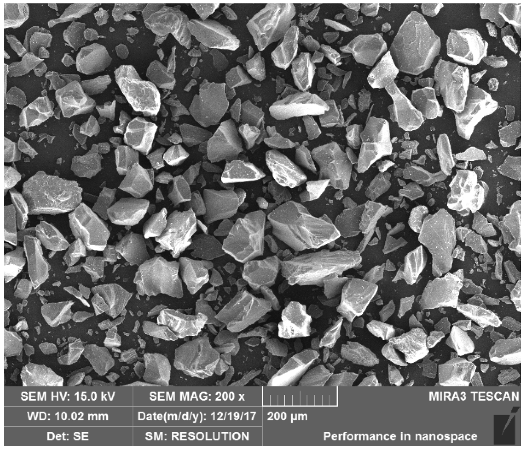
Erosion tests were performed using quartz sand (SiO2) at room temperature on air jet spray erosion experimental equipment developed by us and equipped with an air compressor, a gas tank, air dryer, air filter, powder feeder, acceleration nozzle, and test chamber. The sand had thickness below 200 μm along with sharp angles, as shown in Figure 1. The sand particles were supplied by the compressed air in the air–particle mixer and gained high kinetic energy along the acceleration nozzle. According to the erosion conditions, the sample is aligned to a certain angle (45°) with respect to the acceleration nozzle. As different sizes of sand have different motion laws under the acceleration of air pressure, the erosion speeds of sand in different grain size ranges under different air pressures were calibrated by using a double-disk speed-measuring device [26].
The particle–air gas stream was directed towards the testing coupon at an impingement angle of 45° with a velocity of 100 m/s, and the 60 g sand particles were employed on both the coated TiN/ZrN multilayer coating samples and the uncoated Ti alloy substrates at room temperature. To intuitively exhibit the erosion resistance mechanism of the coating at high velocity, the single sand particle impact test was conducted on the uncoated substrate and the coated samples with impact angles of 45° and velocity of 100 m/s. To obtain stable erosion data, the uncoated substrate and the coated samples were preflushed with 60 g of sand at the beginning of the erosion test. In this study, the extent of erosion wear was the distinct erosion mass loss calculated using an electronic scale. The reported mass loss was based on five independent measurements. The value of erosion resistance was calculated using Equation (1).
where R is the value of erosion resistance, which represents the ability of the samples to resist erosion of the particles and is the ratio of the quantity of sand supplied to the quality of the sample; mi is the mass loss of the sample; m0 is the mass loss after the uncoated substrate and the coated samples were preflushed; and ms is the total weight of the erosion sand.
We used SEM to observe the eroded regions in order to understand the behavior and mechanism of the erosion damage. The effects of hardness on erosion wear include solid particle hardness (Hp) and impact material hardness (Ht). Therefore, the hardness of the sand particle and the uncoated sample were detected using a Vickers microscope sclerometer (Shanghai Taiming, HXD-1000TMC/LCD, Shanghai, China), and the results are presented in Table 2. Meanwhile, sand rebound tests were also performed at room temperature using air gun equipment equipped with an air chamber, valve, cartridge case, speedometer, separator, and shield. High-speed video (Olympus i-speed 7, Tokyo, Japan) measurements were employed on the sand rebound tests to capture sand behaviors including velocity, route, and fragmentation degrees.
3. Results and Discussion
3.1. Microstructure of the Coating
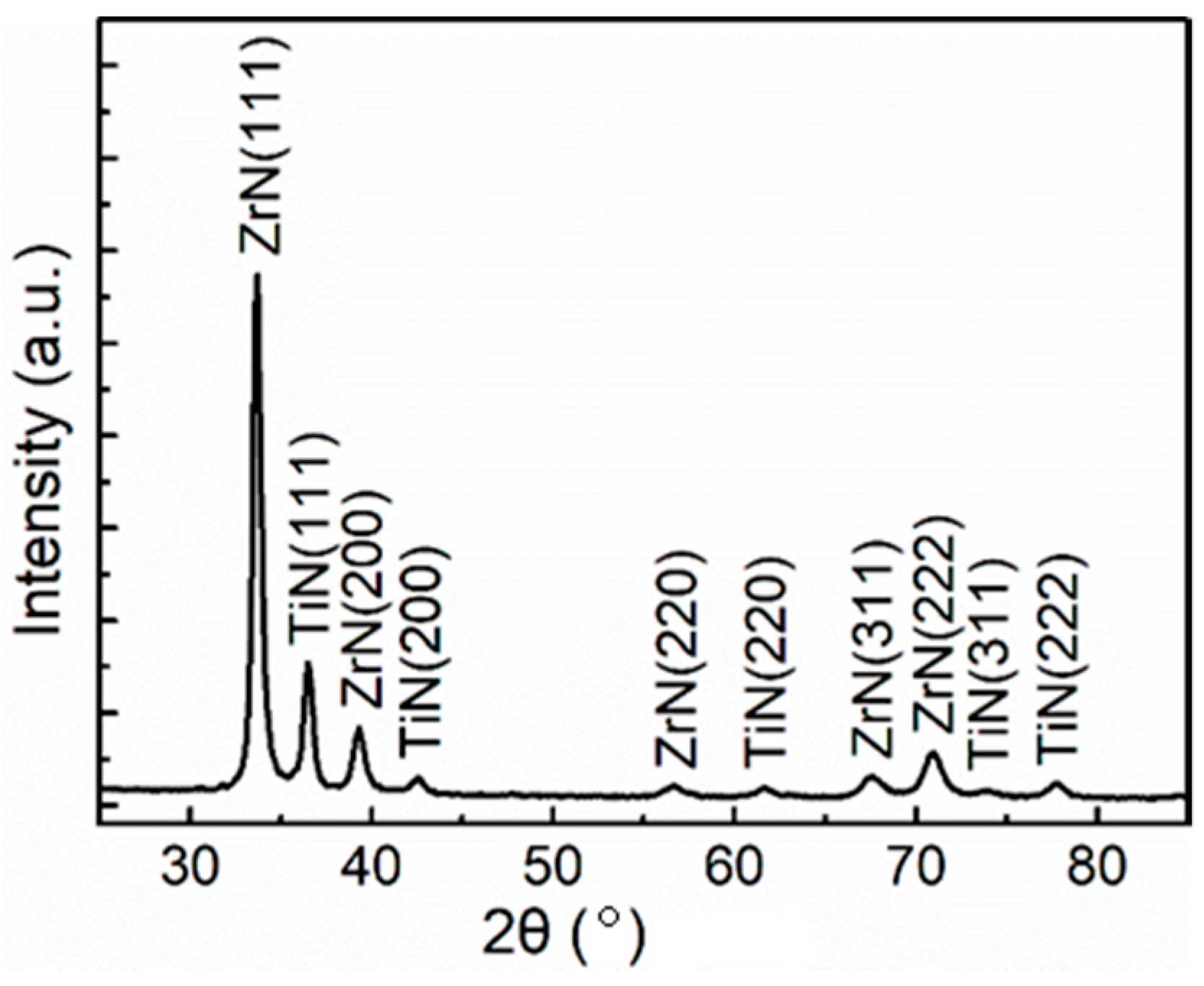
XRD was conducted to assess the structure of the TiN/ZrN multilayer coating deposited on the Ti alloy substrate (Figure 2). The diffraction peaks were indexed as cubic TiN and ZrN according to the JCPDD PDF (02-0956 and 38-1420). The diffraction information is dominated by cubic ZrN and TiN phases. The strongest peak corresponds to the (111) plane of the ZrN phase with a face-centered cubic (FCC) structure.
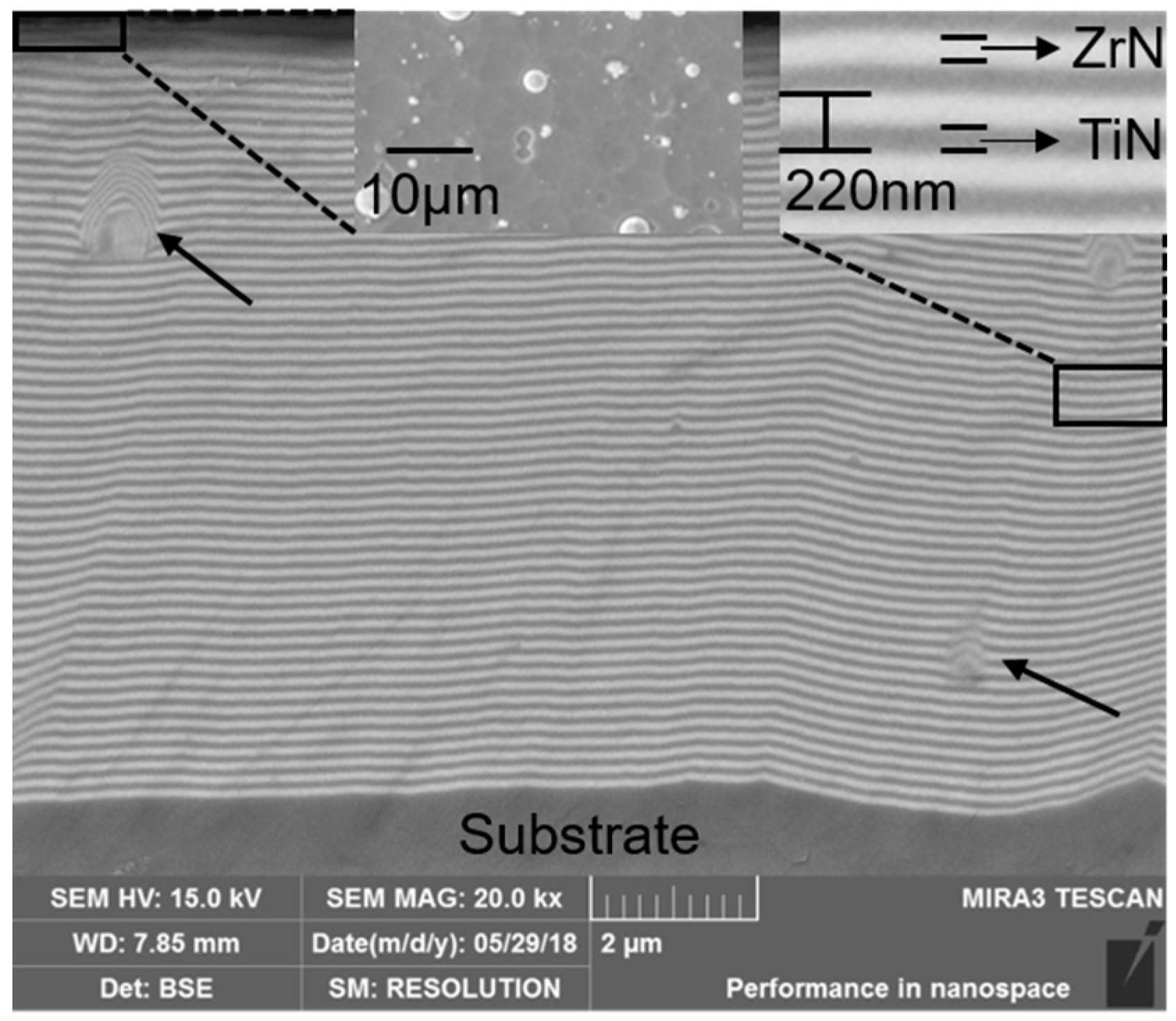
To aid us in understanding the distribution of the two components—TiN and ZrN—in the multilayer coatings, the sectional morphology results of the TiN/ZrN multilayer coatings are shown in Figure 3. The dark layers are TiN and the bright ones are ZrN. The thickness of an individual TiN/ZrN cycle period for coatings with 50 periods is about 200 nm. In the surface morphology of coatings, droplets in the size range of 3–5 μm can be observed. Rare droplets embedded in the multilayer coating were also observed. This is caused by the direct deposition of ionized metal droplets on the sample surface during cathode arc deposition. Furthermore, the TiN/ZrN multilayer coating has a compact structure.
3.2. Mechanical Properties of the Coating
To investigate the effect of the coating on mechanical properties, the erosion, hardness, and elastic modulus of the Ti alloy and the coated sample were tested, as presented in Table 3. The use of parameters such as H/E [27,28], (H/E)1/2 [29], and H3/E2 [28,30] is generally made in order to understanding the erosion behavior of the coating. The ratios H/E and H3/E2 are two parameters that control the resistance of the materials to the elastic strain and plastic deformation, respectively, and have been chosen to define the erosion capability of the studied coatings [5]. In Table 3, we can see that the TiN/ZrN coating results in an increase in the hardness and modulus of the Ti alloy substrate. Second, increased values of H/E and H3/E2 can also be observed for the coated sample in comparison to the uncoated Ti alloy substrate. Moreover, the TiN/ZrN coating has higher hardness and modulus as compared to the Ti alloy. This indicates that the multilayer coating has a higher resistance to plastic deformation as compared to the Ti alloy. The significance of the above discussed factors is discussed in Section 3.3.
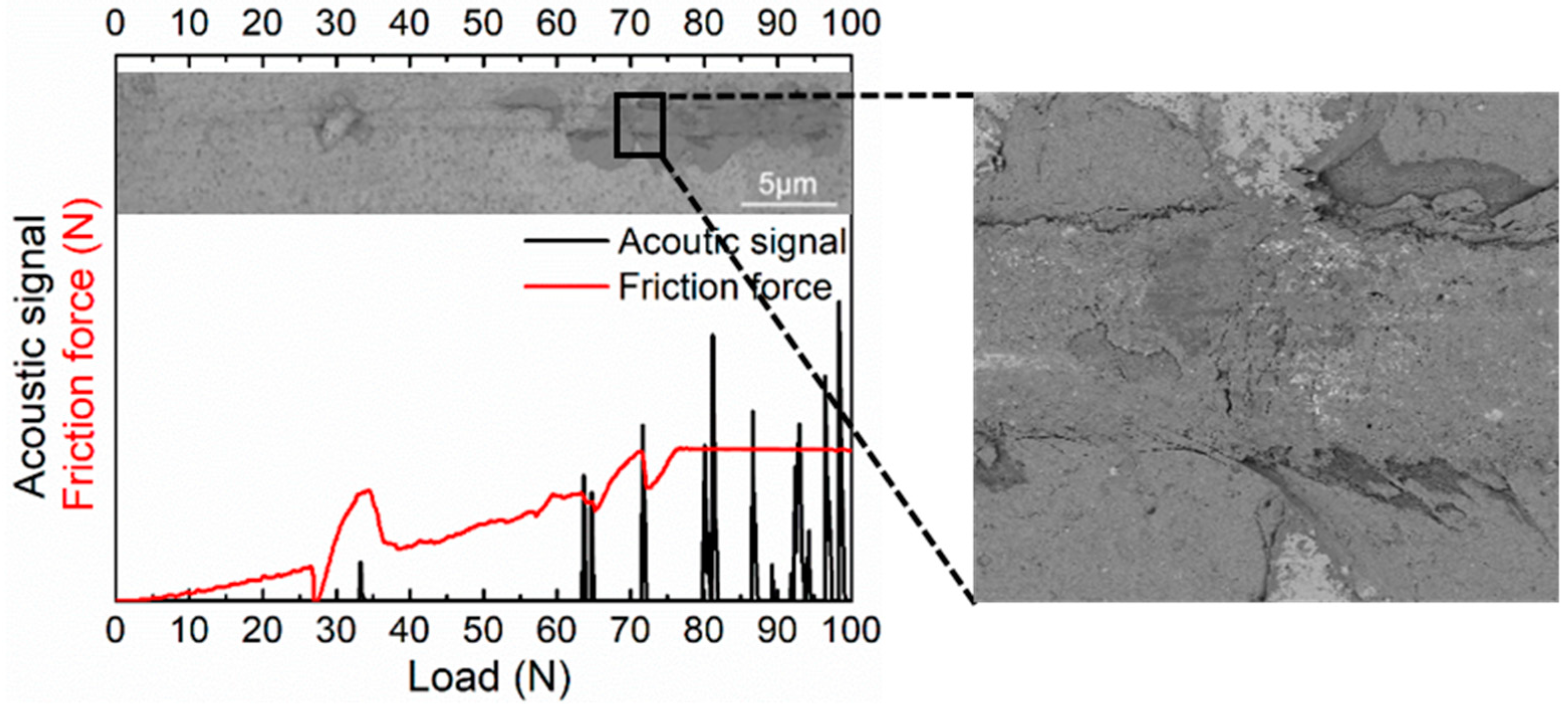
Adhesion is a main factor affecting the erosion resistance of the coating. A high adhesive strength means that coatings will not easily flake. Figure 4 shows displays the scratch morphology and acoustic emission curve of the coating. The coating maintains integrity under a 65 N load. In this range, the friction curve increases linearly with increasing load, and the acoustic signal does not fluctuate obviously. Near 65 N, however, the friction force and acoustic signal do fluctuate obviously. Combining the scratch morphology, we see that the coating is only spalling off from the surface of the coating, and damage has not happened to the bonding surface of the coating. When the load reaches 72.5 N, the two signals fluctuate firmly, and the coating is broken seriously at the arrow indicated, reaching the loading capacity of the coating. It is worth noting that the friction force and acoustic signal fluctuate obviously near 30 N first; however, this is caused by a surface defect such as a droplet, as shown in Figure 4.
3.3. Erosion Resistance of the Coating
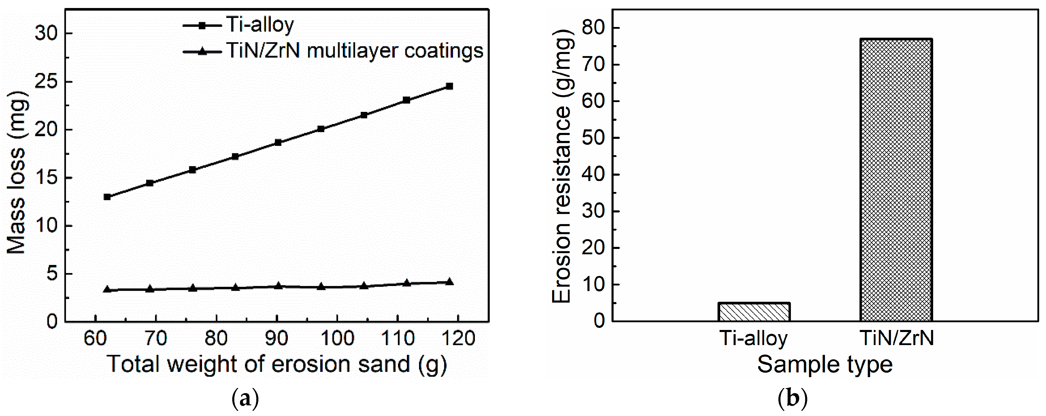
The results show significant differences between the uncoated Ti alloy substrate and the coated sample. The mass loss and erosion resistance rate are shown as a function of mass of sand in Figure 5. Figure 5a shows that for the same amount of sand at a 45° angle, both samples have a linear behavior of the mass loss after a short preflushed erosion, which is called the stable erosion period. Meanwhile, the TiN/ZrN sample shows a much lower mass loss than does the uncoated Ti alloy substrate, which could be ascribed to the higher hardness value of the TiN/ZrN multilayer coatings. Figure 5b shows that the erosion resistance values of the Ti alloy and the TiN/ZrN coating are 5 g/mg and 77 g/m, respectively. Therefore, the erosion resistance rate of the TiN/ZrN coating is 15.5 times higher than that of the uncoated Ti alloy substrate.
In other words, the use of the TiN/ZrN coating as an erosion-protective medium increases the resistance against penetration of the particles into the surface of the sample because of the higher hardness and elastic modulus. Reference [31] identifies the coating hardness (H) and its elastic modulus (E) as the critical parameters that define the resistance of a coating to elastic and plastic deformation. A comparison of H3/E2 between the two samples is presented in Table 3, indicating that the coated sample exhibits higher resistance to plastic deformation than does the uncoated one.
3.4. Erosion Mechanism of the Coating
To investigate the difference between the uncoated and coated samples, in this study, we investigated their failure mechanisms using SEM. The impact motion of the uncoated sample can be decomposed into the tangential movement parallel to the surface and normal movement perpendicular to the surface when the erodent particles impact the surface of the uncoated sample. The horizontal movement is similar to the plowing of a plough.
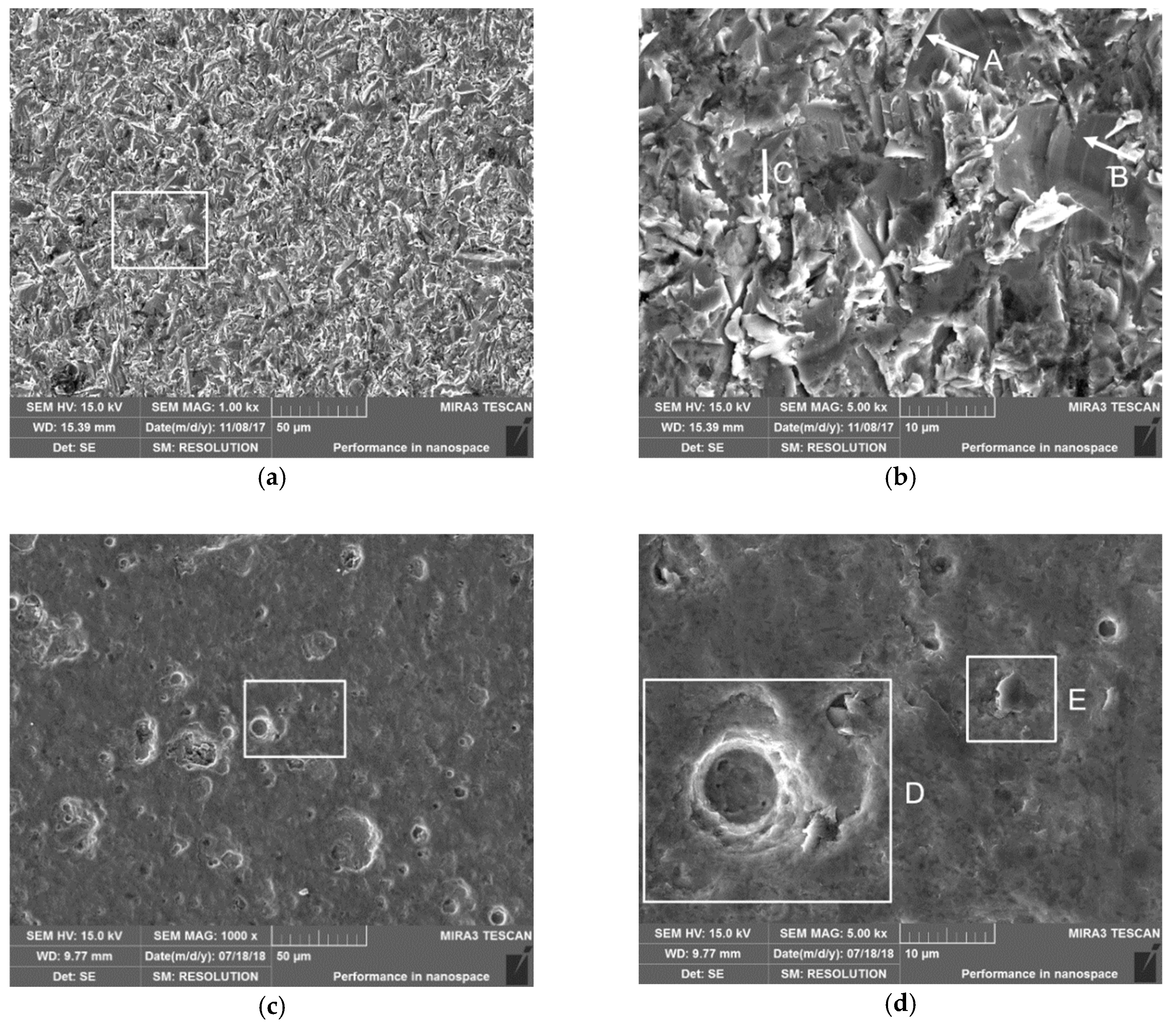
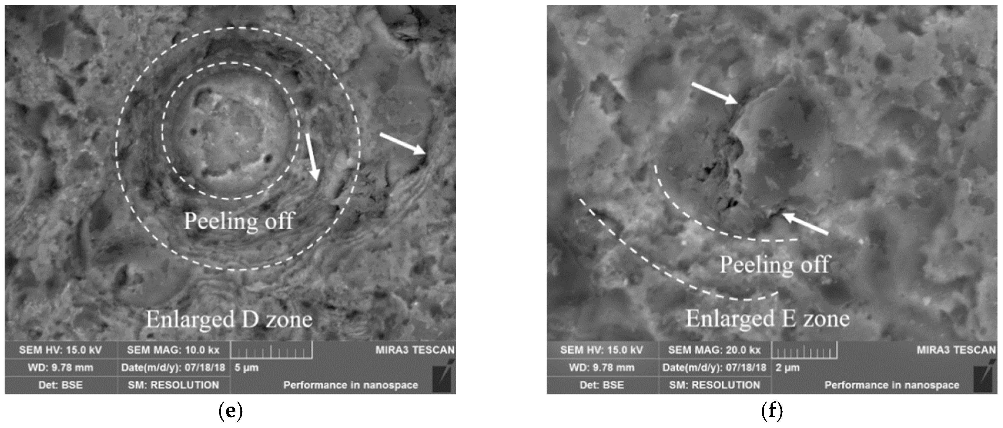
Ti6Al4V is a plastic material; thus, there exist many plows and shovels as shown in Figure 6b at A and B, respectively. The width of plows and shovels is no more than 10 μm, and this size is much smaller than that of the erosion particles, indicating that these plows and shovels are attributed to the edges and corners of erosion particles. Some of the material with a plowed surface is not separated from the substrate; however, it is pressed to the edge of the plow and shovel to form a pressing lip. When the pressing lip is cut off by the tangential force of the erosion particle in the next erosion, the other part of the pressing lip will be forged by the normal force of the erosion particle to form the accumulation of the lip at C as shown in Figure 6b, which is called a deformed lip. Briefly, the uncoated sample shows typical plastic erosion, and plow and shovel erosions play a critical role in the low-angle erosion.
The coated sample exhibits a much higher erosion resistance rate because of its multilayer interface structure. Compared to the uncoated sample, the hardness of the multilayer coatings is higher than that of the erosion sand, as shown in Table 3, which can be interpreted in Figure 7a,d. Therefore, the erosion particles are parallel to the surface of the sample and the plough or shovel caused by the movement is hardly observed, as shown in Figure 6c–f. Figure 6e,f show that coating shedding occurs from droplets and stress concentrations. In Figure 6e,f, cracks can be seen at arrows and peeling off can be seen along the dotted lines. Under repeated erosion by sand, the cracks continue to expand and connect, eventually leading to coating detachment. Wheeler et al. [7] reported similar results in the case of diamond coatings deposited by chemical vapor evaporation.
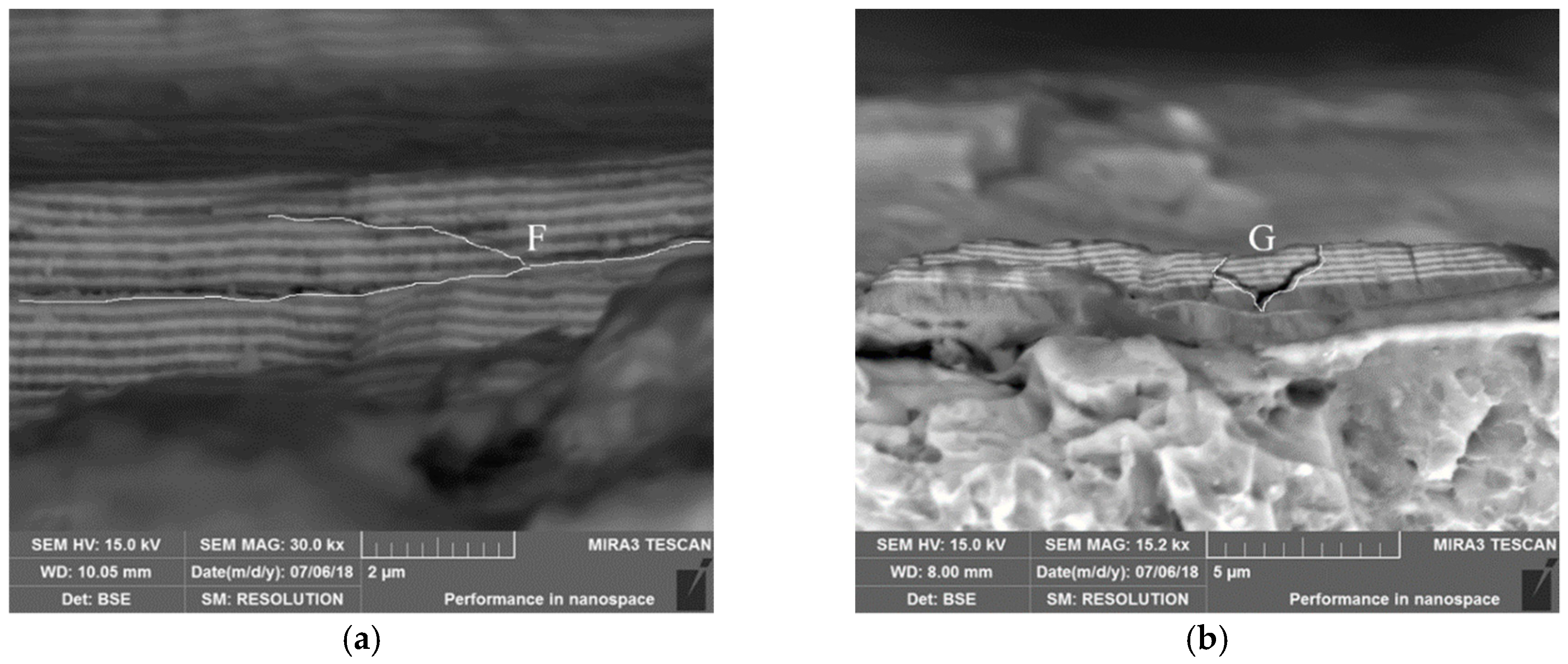
To understand the influence of the peeling off behavior of the coatings on the erosion resistance, the sectional morphology of the coating erosion zone was observed by SEM. As shown in Figure 7a,b, the cracks can be branched (zone F) and deflected (zones G) when they propagate in the multilayer coatings. Branched cracks can weaken the intensive stress distribution ahead of the crack tip. The multilayer coating exhibits better resistance against crack extension. Therefore, the TiN/ZrN nanoscale multilayer coating exhibits greater potential for practical applications in the field of erosion-resistant materials because of its higher bearing capacity.
3.5. Impacting Behavior of Sand on the Coating
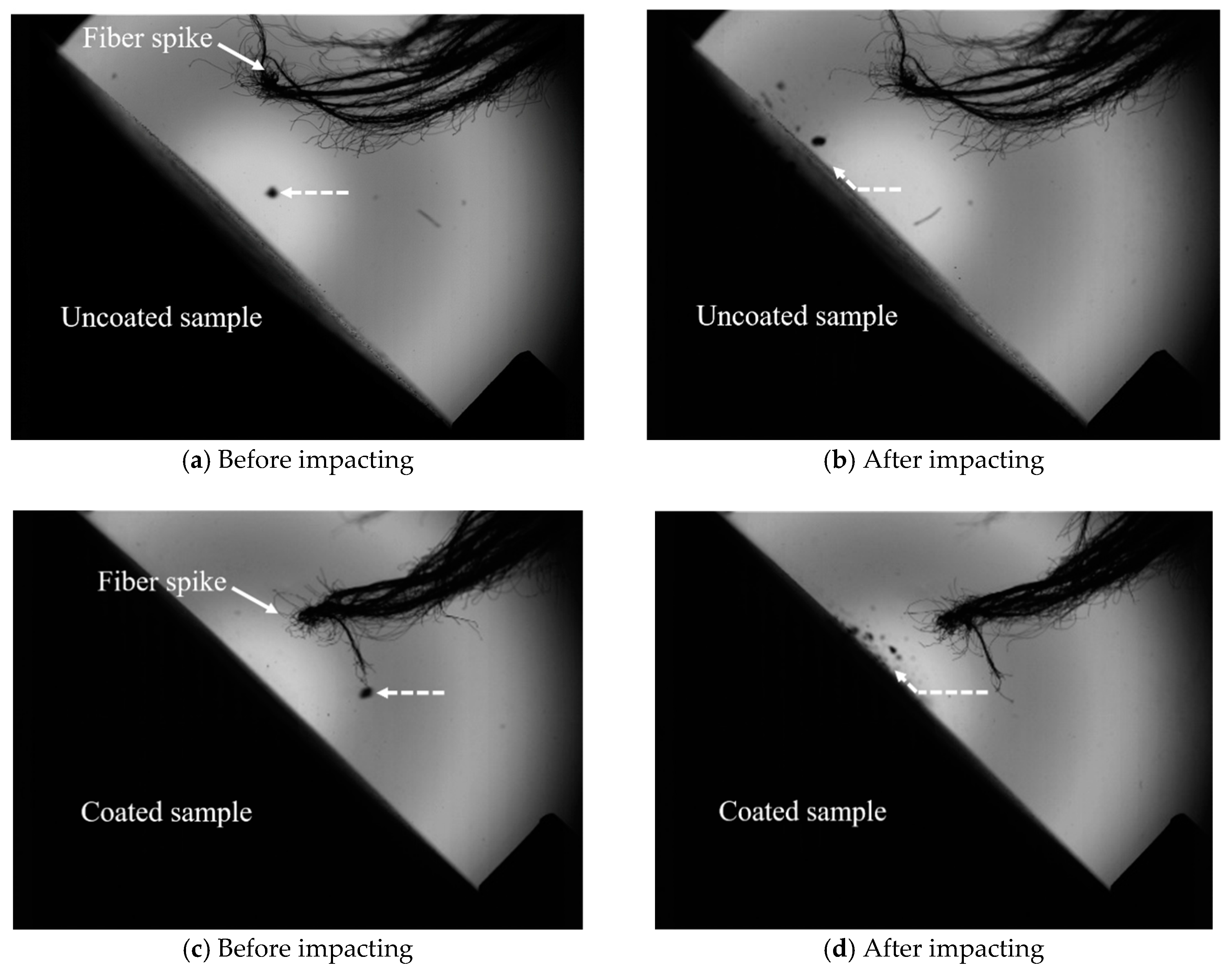
Whereas the erosion resistance of Ti alloy with the coating is improved significantly, high-speed video analysis performed in this work revealed another phenomenon that might contribute to deeper understanding of the mechanism of sand particle erosion. Figure 8 presents two frames before and after impact that demonstrate the fragmentation of a sand particle upon collision with the specimen surface. Sand impacting the coated sample breaks more intensively and rebounds harder compared to that impacting the uncoated sample, thus facilitating substrate protection. The fiber spike is for focusing to make shooting clearer. Hence, it can be argued that the impact energy for the uncoated sample is transferred into the plastic deformation of the Ti alloy. Consequently, sand is only slightly broken. However, impact energy on the coated sample is transferred into the rebounding of the sand. This phenomenon has already been observed and reported elsewhere for CVD diamonds and B13C2 [32,33]. Srinivasan et al. [34] reported that the ratio of Hp to Ht plays a key role in the erosion wear of brittle materials. As shown in Table 2, for the uncoated sample, Hp/Ht > 1, and for the coated sample, Hp/Ht < 1. In contrast, for the coated sample, the TiN/ZrN coating is a brittle material with higher hardness than sand particles, which results in the impact energy transferring to the breakage of sand. In other words, combined with Figure 5, we see that the relationship between material hardness and erosion resistance is as follows: When Hp/Ht is less than 1, the erosion resistance rate of the material is relatively small. When Hp/Ht is greater than 1, the material is eroded by particles with larger hardness and the erosion resistance rate of the material is relatively high. Therefore, increasing the hardness of the eroded particles can obviously improve the erosion resistance rate of the samples. In contrast, increasing the hardness of the matrix will reduce the impact of high-speed erosion particles on the surface of the sample, thus weakening the cutting effect and reducing the erosion resistance rate.
4. Conclusions
In this study, a TiN/ZrN nanoscale multilayer coating was prepared by the PVD process to improve the erosion resistance of the Ti6Al4V titanium alloy. To estimate the erosion resistance and damage mechanism of the coating, erosion testing was conducted at 45° and 100 m/s velocity. The results can be summarized as follows:
- The TiN/ZrN nanoscale multilayer coating has a higher potential for practical applications in the field of erosion-resistant materials. The erosion resistance rate of the Ti6Al4V titanium alloy with the TiN/ZrN coating is 15.5 times higher than that of the uncoated one because of its microstructure, higher hardness, and elastic modulus.
- Droplets on the surface and internal stress in the coating formed during the deposition process are the main reasons for decreased erosion resistance of the coating. Therefore, it is important to improve the surface quality of the coating when preparing the coating.
- For the uncoated Ti alloy substrate, plows and shovels dominate the material failure at a 45° impact angle, thereby exhibiting plasticity. For the coated samples, the mechanism of material removal is crack deflection, crack branching, and successful interaction between them, thus showing brittleness.
Author Contributions
Conceptualization, G.H.; Formal Analysis, J.C.; Investigation, Y.C.; Resources, Y.L. and Z.Y.; Data Curation, M.G.; Writing—Original Draft Preparation, J.C.; Writing—Review and Editing, G.H.
Funding
This research was funded by the National Natural Science Foundation of China (No. 51405506).
Acknowledgments
The Guangdong Institute of New Materials partner supported the coating deposition facilities.
Conflicts of Interest
The authors declare no conflict of interest.
References
- Sharma, S.; Padenko, E.; Bijwe, J.; Wetzel, B.; Friedrich, K. Erosive and sliding wear of polybenzimidazole at elevated temperatures. J. Mater. 2016, 51, 262–270. [Google Scholar] [CrossRef]
- Li, B.B.; Xu, Q.; Zhao, J.B.; Hong, Y. Particle Diameter on Erosion Resistance of Dust Removing and Washing Machine. J. Nanjing Normal Univ. 2017, 17, 51–56. [Google Scholar] [CrossRef]
- Dai, W.; Cremaschi, S.; Subramani, H.J.; Gao, H.J. Uncertainty Quantification in Erosion Predictions using Data Mining Methods. Wear 2018, 408, 108–119. [Google Scholar] [CrossRef]
- Kumar, K.; Kumar, S.; Singh, G.; Singh, J.P.; Singh, J. Erosion Wear Investigation of HVOF Sprayed WC-10Co4Cr Coating on Slurry Pipeline Materials. Coatings 2017, 7, 54. [Google Scholar] [CrossRef]
- Cai, J.M.; Cao, C.X. Alloy Design and Application Expectation of a New Generation 600 °C High Temperature Titanium Alloy. J. Aeronaut. Mater. 2014, 34, 27–36. [Google Scholar] [CrossRef]
- Deng, J.X.; Wu, F.F.; Lian, Y.S.; Xing, Y.Q.; Li, S.P. Erosion wear of CrN, TiN, CrAlN, and TiAlN PVD nitride coatings. Int. J. Refract. Met. Hard Mater. 2012, 35, 10–16. [Google Scholar] [CrossRef]
- Wheeler, D.W.; Wood, R.J.K. High velocity erosion of CVD diamond coatings by diamond particles. Diam. Relat. Mater. 2018, 84, 32–40. [Google Scholar] [CrossRef]
- Lin, S.S.; Zhou, K.S.; Dai, M.J.; Lan, E.H.; Shi, Q.; Hu, F.; Kuang, T.C.; Zhuang, C.Q. Structural, mechanical, and sand erosion properties of TiN/Zr/ZrN multilayer coatings. Vacuum 2015, 122, 179–186. [Google Scholar] [CrossRef]
- Guo, L.; Chen, G.H. High-quality diamond film deposition on a titanium substrate using the hot-filament chemical vapor deposition method. Diam. Related Mater. 2007, 16, 1530–1540. [Google Scholar] [CrossRef]
- Li, Y.S.; Zhang, C.Z.; Ma, H.T.; Yang, L.Z.; Zhang, L.L.; Tang, Y.; Li, X.J.; He, L.L.; Feng, R.; Yang, Q.; et al. CVD nanocrystalline diamond coatings on Ti alloy: A synchrotron-assisted interfacial investigation. Mater. Chem. Phys. 2012, 134, 145–152. [Google Scholar] [CrossRef]
- Bielawski, M.; Beres, W. FE modelling of surface stresses in erosion-resistant coatings under single particle impact. Wear 2007, 262, 167–175. [Google Scholar] [CrossRef]
- Di, J.; Wang, S.S.; Zhang, L.; Cai, L.X.; Xie, Y.H. Study on the erosion characteristics of boride coatings by finite element analysis. Surf. Coat. Technol. 2018, 333, 115–124. [Google Scholar] [CrossRef]
- Ikeda, R.; Hayashi, M.; Yonezu, A.; Ogawa, T.; Takemoto, M. Fracture observation of polycrystalline diamond film under indentation test. Diam. Related Mater. 2004, 13, 2024–2030. [Google Scholar] [CrossRef]
- Wiklund, U.; Hedenqvist, P.; Hogmark, S. Multilayer cracking resistance in bending. Surf. Coat. Technol. 1997, 97, 773–778. [Google Scholar] [CrossRef]
- Deng, W.; An, Y.; Hou, G.; Li, S.J.; Zhou, H.D.; Chen, J.M. Effect of substrate preheating treatment on the microstructure and ultrasonic cavitation erosion behavior of plasma-sprayed YSZ coatings. Ultrason. Sonochem. 2018, 46, 1–9. [Google Scholar] [CrossRef]
- Eaton, H.E.; Zajchowski, P. High temperature particulate erosion of plasma sprayed YSZ versus selected powder characteristics and plasma torch designs. Surf. Coat. Technol. 1999, 120–121, 28–33. [Google Scholar] [CrossRef]
- Yang, G.J.; Li, C.J.; Li, C.X.; Katsuyoshi, K.; Akira, O. Improvement of adhesion and cohesion in plasma-sprayed ceramic coatings by heterogeneous modification of nonbonded lamellar interface using high strength adhesive infiltration. J. Therm. Spray Technol. 2013, 22, 36–47. [Google Scholar] [CrossRef]
- Li, C.J.; Yang, G.J.; Ohmori, A. Relationship between particle erosion and lamellar microstructure for plasma-sprayed alumina coatings. Wear 2006, 260, 1166–1172. [Google Scholar] [CrossRef]
- Cheng, B.; Zhang, Y.M.; Yang, N.; Zhang, M.; Chen, L.; Yang, G.J.; Li, C.J.; Li, C.X. Sintering-induced delamination of thermal barrier coatings by gradient thermal cyclic test. J. Am. Ceram. Soc. 2016, 100, 1820–1830. [Google Scholar] [CrossRef]
- Rangarajan, S.; King, A.H. Non-destructive evaluation of delamination in ceramic thin films on metal substrates by scanning electron microscopy. Thin Solid Films 2001, 385, 22–28. [Google Scholar] [CrossRef]
- Rao, J.; Sharma, A.; Rose, T. Titanium aluminium nitride and titanium boride multilayer coatings designed to combat tool wear. Coatings 2017, 8, 12. [Google Scholar] [CrossRef]
- Plotnikov, S.V.; Pogrebnyak, A.D.; Tleukenov, Y.O.; Erdybaeva, N.K. Functional properties of multilayer vacuum-arc TiN/ZrN coatings. In Proceedings of the IOP Conference Series-Materials Science and Engineering, Tomsk, Russia, 5–9 October 2016. [Google Scholar]
- Pradhaban, G.; Kuppusami, P.; Ramachandran, D.; Viswanathan, K.; Ramaseshan, R. Nanomechanical properties of TiN/ZrN multilayers prepared by pulsed laser deposition. Mater. Today Proc. 2016, 3, 1627–1632. [Google Scholar] [CrossRef]
- Xu, X.M.; Wang, J.; An, J.; Zhao, Y.; Zhang, Q.Y. Effect of modulation structure on the growth behavior and mechanical properties of TiN/ZrN multilayers. Surf. Coat. Technol. 2005, 201, 5582–5586. [Google Scholar] [CrossRef]
- Oliver, W.C.; Pharr, G.M. An improved technique for determining hardness and elastic modulus using load and displacement sensing indentation experiments. J. Mater. Res. 1992, 7, 1564–1583. [Google Scholar] [CrossRef]
- Geng, M.R.; Chen, J.; Yang, Z.F.; Liu, M.J.; He, G.Y.; Wang, X.D. Dependent Effect of Particle Size on Erosion Wear Mechanism of TC4 Titanium Alloy. China Surf. Eng. 2018, 31, 17–26. [Google Scholar] [CrossRef]
- Leyland, A.; Matthews, A. On the significance of the H/E, ratio in wear control: A nanocomposite coating approach to optimised tribological behaviour. Wear 2000, 246, 1–11. [Google Scholar] [CrossRef]
- Hassani, S.; Klemberg-Sapieha, J.E.; Martinu, L. Mechanical, tribological and erosion behaviour of super-elastic hard Ti–Si–C coatings prepared by PECVD. Surf. Coat. Technol. 2010, 205, 1426–1430. [Google Scholar] [CrossRef]
- Marshall, D.B.; Lawn, B.R.; Mecholsky, J.J. Effect of Residual Contact Stresses on Mirror-Flow-Size Relations. J. Am. Ceram. Soc. 1980, 63, 358–360. [Google Scholar] [CrossRef]
- Recco, A.A.C.; Oliveira, I.C.; Massi, M.; Maciel, H.S.; Tschiptschin, A.P. Adhesion of reactive magnetron sputtered TIN x, and TIC y, coatings to AISI H13 tool steel. Surf. Coat. Technol. 2007, 202, 1078–1083. [Google Scholar] [CrossRef]
- Musil, J.; Zeman, H.; Kunc, F.; Vlcek, J. Measurement of hardness of superhard films by microindentation. Mater. Sci. Eng. A 2003, 340, 281–285. [Google Scholar] [CrossRef]
- Bose, K.; Wood, R.J.K. High velocity solid particle erosion behaviour of CVD boron carbide on tungsten carbide. Wear 2005, 258, 366–376. [Google Scholar] [CrossRef]
- Wheeler, D.W.; Wood, R.J.K. Erosive wear behaviour of thick chemical vapour deposited diamond coatings. Wear 1999, 225–229, 523–536. [Google Scholar] [CrossRef]
- Srinivasan, S.; Scattergood, R.O. Effect of erodent hardness on erosion of brittle materials. Wear 1988, 128, 139–152. [Google Scholar] [CrossRef]
Figure 1.
SEM micrographs of the erosion sand.

Figure 2.
XRD diffraction pattern of the TiN/ZrN nanoscale multilayer coating.

Figure 3.
Sectional morphologies of the TiN/ZrN multilayer coatings.

Figure 4.
Scratch morphologies and back scattered-electron image of the TiN/ZrN nanoscale multilayer coating.
Figure 4.
Scratch morphologies and back scattered-electron image of the TiN/ZrN nanoscale multilayer coating.

Figure 5.
Mass loss and erosion resistance of the uncoated Ti alloy sample and the TiN/ZrN-coated sample.
Figure 5.
Mass loss and erosion resistance of the uncoated Ti alloy sample and the TiN/ZrN-coated sample.

Figure 6.
SEM micrographs of uncoated and coated samples after 60 g erosion testing: (a,b) are the uncoated sample, (c) is the erosion area, (d) is an enlargement of the white frame in (c), and (e,f) are an enlargement of the failed area with droplets defects (D) and stress concentration defects (E) during the coating process.


Figure 7.
(a) Crack deflection and (b) crack branching of the TiN/ZrN multilayer coating.

Figure 8.
Impacting behavior of sand on an uncoated Ti alloy sample and on the sample coated with TiN/ZrN.
Figure 8.
Impacting behavior of sand on an uncoated Ti alloy sample and on the sample coated with TiN/ZrN.


Table 1.
Chemical composition of the Ti6Al4V titanium alloy.
| Element | Ti | Al | V | Fe | C | O | N | H |
|---|---|---|---|---|---|---|---|---|
| Content (%) | Bal | 5.70 | 4.00 | 0.10 | 0.02 | 0.05 | <0.01 | <0.001 |
Table 2.
Testing hardness results of sand particle, Ti6Al4V, and TiN/ZrN.
| Sample | Test Force | Hardness |
|---|---|---|
| Sand | 0.98 N (100 gf) | 1226 ± 176 |
| Ti6Al4V | 0.098 N (10 gf) | 277 ± 2 |
| TiN/ZrN | 0.98 N (100 gf) | 3433 ± 39 |
Table 3.
Hardness and modulus of Ti6Al4V and the TiN/ZrN nanoscale multilayer coating.
| Sample | H (GPa) | E (GPa) | H/E | H3/E2 (10−2 GPa) |
|---|---|---|---|---|
| Ti6Al4V | 3.95 ± 0.8 | 130 ± 10.5 | 0.030 | 0.36 |
| TiN/ZrN | 39.1 ± 1.6 | 550.7 ±17.5 | 0.071 | 19.7 |
© 2019 by the authors. Licensee MDPI, Basel, Switzerland. This article is an open access article distributed under the terms and conditions of the Creative Commons Attribution (CC BY) license (http://creativecommons.org/licenses/by/4.0/).
Share and Cite
MDPI and ACS Style
Chen, J.; Geng, M.; Li, Y.; Yang, Z.; Chai, Y.; He, G. Erosion Resistance and Damage Mechanism of TiN/ZrN Nanoscale Multilayer Coating. Coatings 2019, 9, 64. https://doi.org/10.3390/coatings9020064
AMA Style
Chen J, Geng M, Li Y, Yang Z, Chai Y, He G. Erosion Resistance and Damage Mechanism of TiN/ZrN Nanoscale Multilayer Coating. Coatings. 2019; 9(2):64. https://doi.org/10.3390/coatings9020064
Chicago/Turabian StyleChen, Jiao, Mingrui Geng, Yuqin Li, Zhufang Yang, Yan Chai, and Guangyu He. 2019. "Erosion Resistance and Damage Mechanism of TiN/ZrN Nanoscale Multilayer Coating" Coatings 9, no. 2: 64. https://doi.org/10.3390/coatings9020064
Note that from the first issue of 2016, this journal uses article numbers instead of page numbers. See further details here.