Hot Corrosion Resistance of Laser-Sealed Thermal-Sprayed Cermet Coatings
by
 , , ,
, , ,
Lidia Baiamonte
1 ,
,
Cecilia Bartuli
1,*,
Francesco Marra
1,
Annamaria Gisario
2 and 
Giovanni Pulci
1 1
LIMS, INSTM Reference Laboratory for Engineering of Surface Treatments, Department of Chemical Engineering Materials Environment, Sapienza University of Rome, Via Eudossiana 18, 00184 Rome, Italy
2
Department of Mechanical and Aerospace Engineering, Sapienza University of Rome, Via Eudossiana 18, 00184 Rome, Italy
*
Author to whom correspondence should be addressed.
Coatings 2019, 9(6), 347; https://doi.org/10.3390/coatings9060347
Submission received: 12 March 2019
/
Revised: 24 May 2019
/
Accepted: 25 May 2019
/
Published: 28 May 2019
(This article belongs to the Special Issue Coatings for Harsh Environments)
Abstract
:Hot corrosion affects the components of diesel engines and gas turbines working at high temperatures, in the presence of low-melting salts and oxides, such as sodium sulfate and vanadium oxide. Thermal-sprayed coatings of nickel–chromium-based alloys reinforced with ceramic phases, can improve the hot corrosion and erosion resistance of exposed metals, and a sealing thermal, post-treatment can prove effective in reducing the permeability of aggressive species. In this study, the effect of purposely-optimized high-power diode laser reprocessing on the microstructure and type II hot corrosion resistance of cermet coatings of various compositions was investigated. Three different coatings were produced by high velocity oxy-fuel and was tested in the presence of a mixture of Na2SO4 and V2O5 at 700 °C, for up to 200 h: (i) Cr3C2–25% NiCr, (ii) Cr3C2–25% CoNiCrAlY, and (iii) mullite nano–silica–60% NiCr. Results evidenced that laser sealing was not effective in modifying the mechanism, on the basis of the hot corrosion degradation but could provide a substantial increase of the surface hardness and a significant decrease of the overall coating material consumption rate (coating recession), induced by the high temperature corrosive attack.
1. Introduction
Hot corrosion is a severe degradation mechanism that occurs on steels and superalloys exposed to aggressive oxidizing environments, at high temperatures, in the presence of low-melting salts or oxides, which induce accelerated damage to the protective surface oxide layers [1].
The most commonly affected components are the nozzle guide vanes and rotor blades in the hot sections of gas turbines, which can get covered with deposits of sodium sulfate (formed by the reaction of sulfur from the fuel and sodium chloride from sea water) and vanadium oxide (formed from the oxidation of the vanadium present as an impurity in the combustion fuel) [2].
Two types of hot corrosion (known as type I and type II) occur in different and specific temperature ranges—type I attack is observed at 800–900 °C, in the presence of totally molten salt deposits that act to disrupt the surface oxide with a sudden and important increase in the corrosion rate; type II mechanism is active at lower temperatures (670–750 °C), and is characterized by a more localized attack, with little or no material loss underneath the pit [2].
Type II hot corrosion, rarely observed in aeroengines, is more frequently experienced by marine and industrial gas turbines that generally operate at lower temperatures.
Type II corrosion mechanism has often been proposed to be a liquid-phase attack by the mixed sulfates in the molten state [3,4], initiating corrosion by fluxing the protective oxide layer and rapidly propagating degradation by transporting the reactive species through the liquid, in the corrosion pits. However, more recent studies [5], do not support the molten sulfate attack theory, and rather indicate a solid reaction process involving the cooperative formation of nanosized sulfides and oxides, during corrosion front propagation.
The selection of materials for the construction of components operating in such extreme environments requires specific attention [1,2,3,4,5,6,7,8]. Nickel-base alloys are more resistant to type II hot corrosion than cobalt-base alloys; and NiCrAlY and NiCoCrAlY coatings are generally more resistant than CoCrAlY coatings. Additionally, increasing the chromium content improves the resistance of the material to both type I and type II hot corrosion attack [2].
Erosion resistance is often an additional important requirement for the coatings operating in the hot sections of gas turbines. Thermal-sprayed [9], chromium-based cermet coatings represent a viable option when it is necessary to provide high hardness and corrosion resistance at temperatures up to 900 °C [10,11,12]. Corrosion resistance and toughness are provided by the metallic matrix, while the wear resistance is mainly offered by the dispersed (usually carbide-based), ceramic phase.
Coating microstructure plays a fundamental role in the combined corrosion-wear resistance [13]. Porosity is certainly the main feature to be controlled, especially in the case of a hot corrosion degradation phenomenon where molten salts characterized by extremely low viscosities can easily penetrate through the permeable coatings. Partial decarburation of the ceramic phase can also represent a relevant issue, being potentially responsible for a decrease in the coating hardness [14,15,16,17], with detrimental consequences on the erosion/corrosion resistance, especially at higher temperatures.
In thermal-sprayed cermets, the specific type of spraying process and the selected deposition parameters can induce substantial variations in the composition and the microstructure of the coatings [18]. Coatings deposited by high velocity oxy-fuel (HVOF) generally exhibit dense microstructures, due to a high powder particle velocity and impact energy, even if relatively low temperatures are achieved in the plume [19,20]. Ni–Cr-based HVOF cermet overlays have, therefore, been proposed as the best-performing coatings, to overcome the serious consequences of hot corrosion in the presence of molten salts, e.g., for applications in power plant boilers [21,22,23].
However, in the most demanding operating conditions, residual porosities of a few percent units can still present a significant limitation, and the coatings applied for corrosion protection need to be made impervious by means of appropriate surface sealing treatments [24,25].
Laser technology has become the object of increasing interest as a viable, affordable, and reliable sealing and densification post-treatment process, in thermal spray coatings, for improving the performance of the coatings [26,27,28,29,30,31,32,33,34,35].
Gisario et al. [30] found consistent improvements in the mechanical properties of Diamalloy coatings deposited by high velocity oxy-fuel (HVOF), by reprocessing them by diode laser at a higher power and a reduced scan speed. Similarly, appropriate combinations of laser parameters have been shown to improve the structure density, hardness, and wear endurance of the WC–Co/NiCr coatings, using diode lasers, post-treatment [31].
Morimoto et al. [32] proposed a study on HVOF Cr3C2–25% NiCr cermet coatings, reprocessed by direct diode laser system. They showed an improvement in the micro-hardness and a material loss of the laser-treated Cr3C2–25% NiCr coatings, as evaluated by the sand erosion testing, and found it to be as low as 50% of that measured on the as-sprayed coatings.
While research on the effect of the CoCrAlY coatings densification processes on type I hot corrosion resistance have been reported in the recent literature [36], no study is currently available that has specifically investigated the effect of laser sealing on hot corrosion resistance of cermet coatings. Efficient densification of cermets is, in fact, expected to be hindered by the thermal coefficients mismatch of the metallic and ceramic phases coexisting in the coating, making the optimization of laser treatment and the formation of a protective densified layer more difficult. In [37], laser densification of HVOF WC–Co NiCr coatings has been reported for oxidation resistance, but surface treatment optimization procedures have not been discussed in detail, nor has the microstructure of densified layers been specifically investigated.
The present work investigated high power diode laser reprocessing of metal–ceramic coatings of various compositions, deposited by HVOF: (a) Cr3C2–NiCr coatings, widely applied on the industrial components working at a high temperature, to improve erosion, corrosion, and oxidation resistance; (b) Cr3C2–MCrAlY (with M = Ni, Co or a combination, thereof) overlay coatings, commonly used in gas turbines to protect the surface of blades against oxidation and hot corrosion; and (c) an original composite coating consisting of a Ni–Cr matrix, containing a combined dispersion of large mullite (3Al2O3⋅2SiO2) particles and silica nanoparticles. The original composite coating was developed in [38], on the basis of studies that have reported that the presence of silicate minerals in Ni-based metallic matrix could be beneficial for the resistance to hot corrosion phenomena, in heavy oil-fueled diesel engines [39,40].
The optimal laser treatment conditions were identified for each type of coating, and the effect of coating densification on composition, microstructure and type II hot corrosion resistance was investigated. The main purpose of the proposed experiment was to produce experimental evidence of the potential beneficial effect of laser sealing procedures on hot corrosion resistance of coatings, rather than offering novel insight for the type II hot corrosion mechanism. Very dissimilar compositions were in fact tested, and no common mechanism could be envisaged for the different investigated coatings.
2. Materials and Methods
2.1. Starting Powders and Coatings Deposition
Two commercially available Cr3C2-based cermet powders were selected for the coatings deposition (composition, size distribution, and suppliers are reported in Table 1)—a standard Cr3C2–NiCr formulation (designated as CRCZ), and a Cr3C2–CoNiCrAlY (CRCY) expressly designed for an improved high-temperature-corrosion-resistance. The fraction of the metal matrix was 25 wt % for both CRCZ and CRCY.
A non-commercial mullite nano–silica–NiCr powder (designated as MSN), originally proposed and developed by the authors in [36], was also included in the experimental campaign, in order to investigate the influence of post-deposition laser treatment on cermet coatings characterized by unconventional ceramic reinforcements, and by a remarkably higher fraction (60 wt %) of the metallic matrix. The powder was obtained by mixing, metallic (NiCr–HC Starck-Amperit 251.051, H.C. Starck GmbH, Goslar, Germany) and ceramic (mullite–Nabaltec Symulox M 72 K0C, Nabaltec AG Schwandorf, Germany) powders, in aqueous suspension, with addition of the nano–silica particles (Grace LUDOX TM50, W.R. Grace, Columbia, MD, USA), with an average diameter of 22 nm. The suspensions were spray-dried to obtain a granulated powder that was sieved to –53 + 20 µm size distribution.
All particle size specifications reported in Table 1 were provided by powder suppliers and were confirmed by sieving and laser scattering granulometry (Malvern Mastersize 2000, Malvern Panalytical Ltd, Malvern, UK).
All materials were deposited onto 3 mm thick, 20 mm in diameter, Nimonic disks, previously sand-blasted with alumina grit, to improve adhesion by mechanical interlocking.
Coatings were deposited by HVOF, using a Praxair Tafa JP-5000 kerosene–oxygen gun (Praxair, Danbyry, CT, USA). The process parameters were previously optimized by the Design of Experiment (DoE) procedures [38], with the aim of producing dense and hard coatings, offering the maximum protection against both penetration of corrosive media and erosion by solid particles; summarized in Table 2.
2.2. Laser Post-Treatment
A diode laser (Rofin Sina DL015), with a wavelength of 940 nm and an elliptical spot size of 3.8 mm × 1.2 mm, with a maximum power of 1500 W, was used for the post-deposition laser treatment of all coatings. Argon was used as an assist gas.
Two laser scanning trajectories were initially tested—a circular spiral-like trajectory (circumference-to-center), characterized by high scan rates, V, of 13–15 mm/s (depending on the position), and a raster trajectory with lower scan rates (3–8.5 mm/s) but which allowed for a better precision and a limited overlapping between subsequent scans. Final laser treatments were performed in raster geometry, mainly for reasons correlated with the requirement of optimal control of the overlapping passes in the central area of the samples, to be used for the hot corrosion resistance experiments.
Based on preliminary “trial and error”-driven tests—aimed at identifying the conditions for a surface sealing without total remelting of the coatings or massive interdiffusion with the substrate— the following variation ranges for the laser treatment parameters (power, W, and scan rate, mm/s) for the three coating compositions were identified—200–800 W and 2–6.5 mm/s for CRCZ, 700–800 W and 3–4 mm/s for CRCY, 200–400 W and 2–4 mm/s for MSN.
A finer tuning of the optimal treatment conditions was then performed investigating the power/scan rate combinations reported in Table 3, Table 4 and Table 5, for CRCZ, CRCY, and MSN, respectively, where the corresponding value of fluence, or radiant exposure, H, was also reported. Fluence represents the radiant energy absorbed by the surface per unit area and was defined as
where H = fluence (J/mm2); P = power (W); tinteraction = interaction time (s) between laser and surface.
H = P ⋅ tinteraction/Aspot
It was observed that the same value of H could be obtained with different combinations of P and V (as in tests 9, 10, and 11, for example). These different combinations were expressly included in the test matrix to investigate the correlation between laser parameters and the kinetics of physico-chemical processes occurring during material/laser interaction.
The selected values of fluence for tests on different materials were strongly dependent on the composition and thermal properties of the metallic matrix and ceramic reinforcement. Fluence for the treatment of MSN coatings was generally much lower, taking into account the limited fraction of ceramic phase, in this last composition.
2.3. Hot Corrosion Tests
Hot corrosion tests simulating type II hot corrosion were carried out in air, at 700 °C, on both the as-sprayed and the laser-treated samples. A paste made of a mixture of 40 wt % Na2SO4–60 wt % V2O5 dispersed in distilled water, was applied on the central portion of the coated discs (0.8 cm2), obtaining a total salt concentration of 3 mg/cm2. To avoid salt dispersion during high temperature exposure, a refractory cement was used to mask the outer circular area of the disks. The slurry was then dried, and the sample was placed in the furnace for a high temperature cycle. At the end of each cycle, a sample for every coating, in both, the as-sprayed and laser-treated condition, was analyzed, as described below, to investigate the corrosion scale evolution. At least 20 measures of corrosion layer thickness were performed for each observed sample. On the remaining samples, the salt mixture was refurbished to perform a new cycle. Evaluation analyses were carried out after 50, 100, and 200 h of exposure.
2.4. Coatings Characterization
Characterization of the laser-treated coatings was carried out by visual inspection of the top view, by optical microscopy (Nikon Eclipse L150, Nikon Instruments Europe B.V., Amsterdam, the Netherlands), assisted by image analysis software Leica Qwin V. 2.2 and Lucia™ 4.80), and by scanning electron microscopy (Philips SEM XL40, FEI, Hillsboro, OR, USA), assisted by EDS microanalysis EDAX Octane SDD) of the cross sections.
Optimal laser treatment conditions were identified based on the impact on surface quality, coating thickness and microstructure, and micro and macro-porosity measured by image analysis, hardness, presence of vertical cracks, depth of remelting, and interdiffusion with the substrate.
Hot corrosion resistance of the as-sprayed and laser-sealed coatings was evaluated, using the above-mentioned instrumental techniques, assessing the microstructure and the composition of the corrosion scale, formed after 0, 50, 100, and 200 h corrosion treatments, and estimating the total recession of the coating (difference between the thickness of original coating and the residual thickness of the hot corroded coatings, under the corrosion scale).
Vickers microhardness measurements (HV0.05) were performed, both, on the cross section and on the top surface of the samples, following the ASTM E-384-89 standard [41] using a Leica VMHT microhardness tester (min least 30 measures per sample).
The identification of the crystalline phases in the corrosion scales was carried out by X-ray diffraction analysis (XRD), using a PANalytical X’Pert3 diffractometer (Malvern Panalytical Ltd, Malvern, UK). XRD measurements were carried out at 40 kV and 40 mA, with Cu Kα radiation (λKα1 = 1.540598 Å, λKα2 = 1.544426 Å), with a scan range of 15°–70° (2θ), step size 0.02°, and an acquisition time of 20 s/step.
3. Results and Discussion
3.1. Optimization of the Post-Deposition Laser Treatment
Different laser treatment conditions were tested (three tests for each power/scan rate combination) on the CRCZ, CRCY, and MSN samples. Examples of the laser patterns are shown in Figure 1a–c, respectively.
Different undesired effects (Figure 2) was induced on the coating microstructure and morphology, following the post-deposition laser treatment:
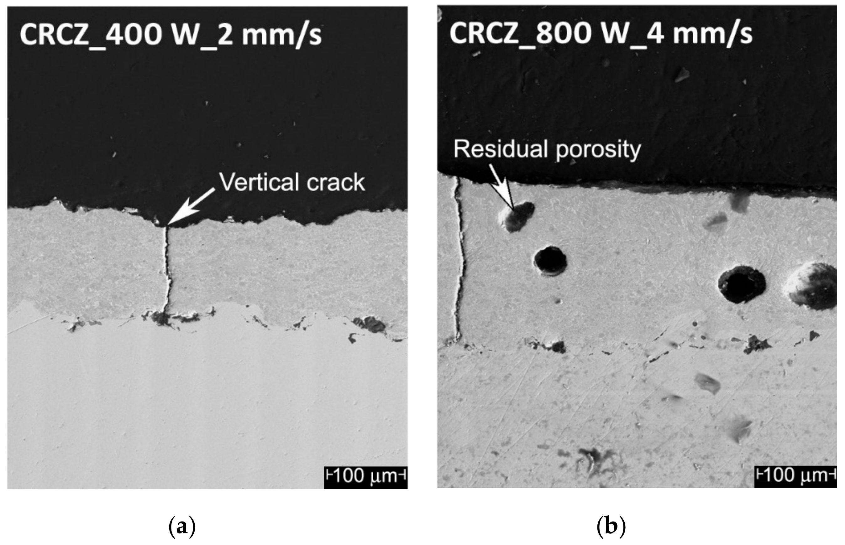
- Iincorporation of large amounts of the shielding gas inside the molten material, with formation of residual macro-porosities in the coating (mainly caused by too high a laser power, in the presence of high scan rates, where the viscosity of the molten material was drastically reduced and the interaction time was not sufficient to allow for proper degassing); Figure 2b, CRCZ coating, track 1, 800 W, 4 mm/s;
- Selective remelting or evaporation and recondensation in the shape of surface droplets of the lower melting fraction of the material (too long interaction times); Figure 2c, MSN coating, track 3, 300 W, 2 mm/s.
Optimal microstructures were identified for the laser treatments, indicated in Table 3, Table 4 and Table 5 with bold character: 200 W-2 mm/s for CRCZ, 700 W-4 mm/s for CRCY, and 300 W-4 mm/s for MSN.
The cross-sections of the as-sprayed coatings are shown in Figure 3a, Figure 4a, and Figure 5a, while the samples treated by the optimal laser process are shown in Figure 3d, Figure 4d, and Figure 5d. It should be noted that the dark areas appearing in the MSN coatings cross-sections corresponded to large mullite grains and are not to be mistaken for porosity.
For Cr3C2–CoNiCrAlY, the desired effect of surface sealing was completely achieved (Figure 4d), and a depth of about half the original coating thickness was effectively densified.
Cr3C2–NiCr coatings exhibited a higher sensitivity to vertical cracking. For this reason, a higher number of laser treatment conditions were evaluated. The optimal treatment parameters were, therefore, selected to minimize the coating fragmentation (Figure 3d). Analogous laser treatment conditions for the Cr3C2–NiCr coatings have also been reported in the literature [32].
Finally, mullite nano–silica–NiCr coatings were found to be highly susceptible to nickel–chrome evaporation and redeposition in spherical droplets of about 200 µm diameter. On the other hand, in coatings treated with intermediate values of power and high scan rates, densification induced by laser interaction with the coating was limited to a thin (about 15 µm) surface layer, as shown in Figure 5d.
For the selected laser-treated coatings, microhardness and porosity were compared with the same features in the as-sprayed conditions. Results are shown in Figure 6 and Figure 7, respectively.
In terms of densification, the best results were achieved for the CRCY coatings, whose porosity was reduced by an order of magnitude (from 3.2% to 0.15%), with a corresponding 50% improvement in hardness. CRCZ and MSN coatings showed negligible differences in terms of porosity (Figure 7) and hardness was measured in the sample cross-section (Figure 6a), highlighting a lack of in-depth microstructure modification, induced by the laser treatments. However, the analysis of the microhardness measured on the top surface of the treated samples (Figure 6b), revealed an increase in the coating hardness, as compared to, both, the top surface of the as-sprayed coatings and cross-section of the laser-treated samples. Specifically, CRCZ–L and MSN–L coatings exhibited an improvement in hardness, as measured on the top surface, by about 20% and 50%, respectively, compared to the untreated samples. These results suggest the presence of thin, harder, surface layers modified by laser treatments, which were barely distinguishable in the cross-section micrographs, and were certainly characterized by a locally-sealed and denser microstructure.
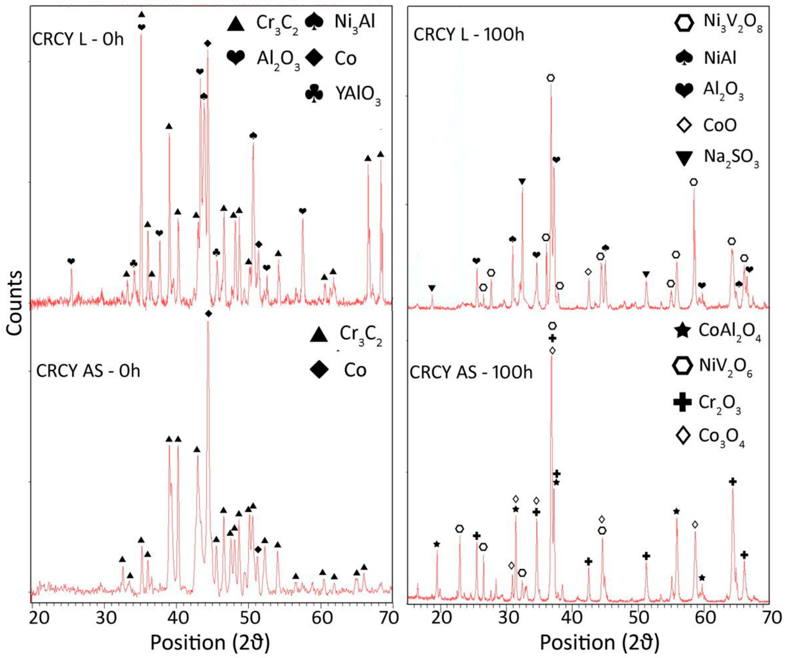
Results of the XRD analyses of the top surfaces are presented in Figure 8, Figure 9 and Figure 10 for the as-sprayed and laser-treated coatings (see left-hand patterns). No significant variations in phase composition were induced by the laser treatment for the CRCZ and MSN compositions, while a certain degree of oxidation of Al and Y was evidenced for the CRCY laser-treated coatings, most probably as a consequence of the higher energy input of the reprocessing conditions.
3.2. Hot Corrosion Results
Following exposure of the as-sprayed and laser-densified samples to the action of aggressive salts at 700 °C for 50, 100, and 200 h, the cross-sections were examined by SEM and the microstructure, thickness, and composition of the scale were evaluated. Cross-sections of the samples exposed for 100 and 200 h are reported in Figure 3b,c, Figure 4b,c and Figure 5b,c, for Cr3C2–NiCr, Cr3C2–CoNiCrAlY and mullite-nanosilica-NiCr, respectively.
3.2.1. Microstructure
Hot corrosion scales appeared generally continuous and free from relevant fragmentation, horizontal cracking, detachment, or spallation, for all coating materials, with the exception of the as-sprayed CRCY exposed for 200 h.
The following evidence was gathered for the individual compositions:
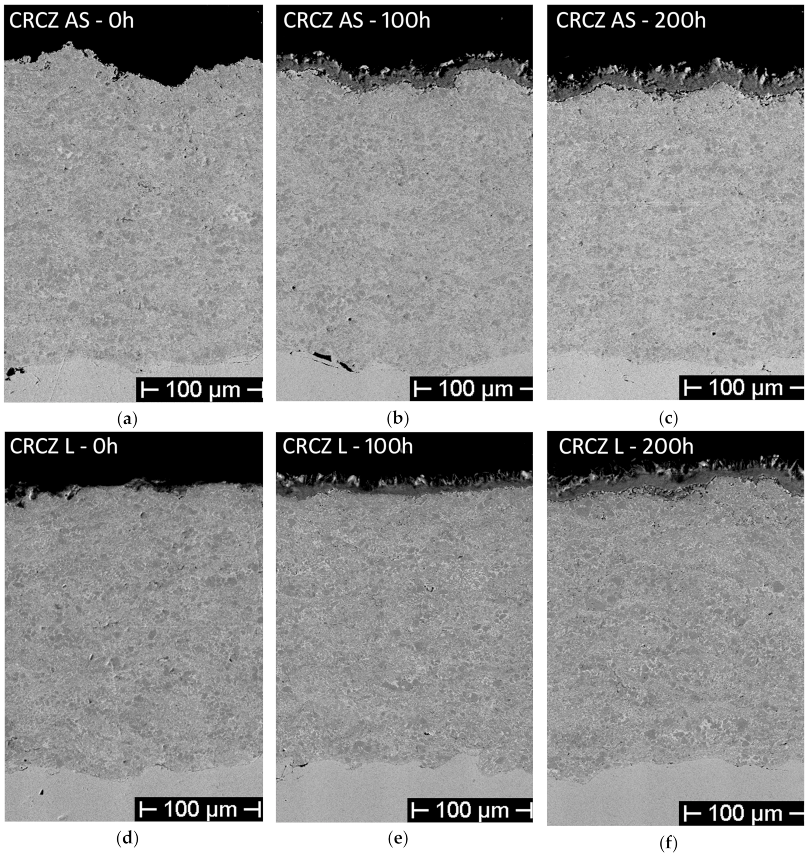
- For the CRCZ as-sprayed coatings (Figure 3a–c), a scale of about 25 µm was formed after 100 h, made of an inner layer of about 10 µm, compact and continuous, and an outer, less dense, coat, characterized by the presence of both acicular and sharp-cornered non-cohesive phases. The same corrosion scale morphology was highlighted in the CRCZ laser-treated samples, after 100 h of exposure test (Figure 11a).
After 200 h, the scale thickness was slightly increased, but the inner compact layer had reached a total thickness of almost 20 µm (Figure 3c).
The laser-treated coatings (Figure 3d–f, Figure 11a) exhibited the same scale microstructure but for each exposure time the thickness of the corrosion layer was lower than the as-sprayed coatings.
- For CRCY, the thickness of the scale increased with the number of hot corrosion cycles for, both, the as-sprayed (Figure 4a–c) and laser-treated coatings (Figure 4d–f), but in this case, a more evident beneficial effect of the sealing treatment could be observed—after 200 h the as-sprayed coatings exhibited a spalled, detached, and thick (≈50 μm) corrosion scale, whereas, the laser-treated samples showed thinner and more compact surface layers formed by hot corrosion products.
- The as-sprayed (Figure 5a,c) and laser-treated (Figure 5d–f) MSN samples did not show significant differences in terms of hot corrosion behavior—the scale thickness was comparable for each exposure time, while the corrosion layers of the laser-treated samples seemed to be slightly more compact and cohesive than the untreated.
3.2.2. Composition of the Scale
Elemental maps of the cross-sections of the laser-treated coatings, after 100 h of hot corrosion exposure, were acquired, to identify the distribution of the original coating elements, throughout the scale thickness, evidencing any diffusion or enrichment phenomenon that had occurred during high temperature exposure, and the presence of elements from the salt mixture, in the corrosion products.
In the laser-treated CRCZ-L coatings (Figure 11a), a clear evidence of the conforming distributions of nickel and vanadium confirmed the formation of a nickel vanadate in the reaction products, concentrated in the superficial layer (about 10 µm thick), where the presence of acicular and cuboidal structures was previously reported. Chromium remained uniformly distributed in the rest of the scale, whereas sodium and sulfur (not shown in Figure 11) were only present in small traces.
EDS microanalysis of the scale formed on the CRCY-L coatings (Figure 11b), evidenced an analogous behavior, but the microstructure of the surface vanadate layer appeared denser and more compact. Moreover, the analysis revealed the presence of cobalt in the outer part of the scale and traces of aluminum, sulfur, and sodium (not reported in Figure 11b), thus, confirming the mechanism involving the migration of cobalt ions proposed in [3].
The MSN-L coatings showed the presence of Ni, Cr, and V, in the corrosion scale, as reported in Figure 11c.
The corrosion products of the hot corroded samples were also analyzed by means of X-ray diffraction—the results are reported in Figure 8, Figure 9 and Figure 10 for the as-sprayed and laser-treated coatings (see right-hand patterns). The composition of the scale was unchanged for the CRCZ compositions in the sealed and unsealed conditions. Sodium sulfate residues were only identified in the scale of laser-treated CRCY coatings, together with cobalt oxides of various stoichiometry and mixed nickel vanadium oxides. The formation of mixed nickel aluminum silicon oxides and nickel vanadium oxides was confirmed for the MSN coatings, with small differences in the stoichiometry of the oxidized phases. These results suggested, in general, that the hot corrosion mechanism was not modified by the coating sealing treatment.
3.2.3. Recession
Results in terms of the coating recession (marked as δ in Figure 5a and measured as the difference between the original thickness of the coating and the thickness of the remaining unaffected coating after the hot corrosion treatment) are shown in Figure 12. Standard deviations were not reported to facilitate the graph readability, and they were all contained between ±10% of the mean value.
Among the as-sprayed coatings (dashed lines), the lowest recession (≈17 µm at 200 h) was exhibited by the CRCZ deposits, while the highest coating consumption affected the CRCY samples (≈30 µm after 200 h). However, the different effectiveness of the laser surface treatment on the coatings of different compositions modified the protection ability of the deposits—Figure 12 shows a significant improvement induced by the laser on the CRCZ coatings (with a final recession of only 13 µm at 200 h) and an almost negligible effect on the MSN coatings. On the other hand, it must be noted that the highest improvement of hot corrosion behavior was shown by the CRCY coatings, for whom the recession decreased from 30 µm before treatment to 19 µm after laser sealing.
4. Conclusions
Ni–Cr based cermet coatings, with different ceramic content and variable metal matrix composition, were treated after the HVOF deposition by a high-power diode laser to induce a surface sealing effect aimed to improve their hot corrosion resistance.
Cermet coatings proved extremely sensitive to the surface treatment parameters (in terms of specific laser power–scan rate combinations), and the identification of optimal laser reprocessing conditions required extensive experimental activities, in order to induce appropriate surface sealing, while avoiding concurrent coating fragmentation, gas incorporation, or substrate remelting.
The results of the corrosion resistance characterization of the as-sprayed and laser-treated coatings (carried out in air, at 700 °C, for up to 200 h in the presence of sodium sulfate and vanadium pentoxide mixture) evidenced that:
- The mechanism of the degradation occurring in typical type II hot corrosion conditions was not substantially altered by the formation of a surface-laser-densified layer, as confirmed by the analysis of the corrosion products of the treated and as-sprayed samples exhibiting an analogous microstructure and composition;
- The formation of surface compact layers (with overall thickness and microstructure very much dependent on coating composition) was responsible for a considerable increase of surface hardness of all coatings, and for a consistent improvement in the hot corrosion resistance, promoting the formation of thinner and more compact corrosion scales, and considerably reducing the surface recession rate (up to 60%, after 200 h exposure for Cr3C2–25% CoNiCrAlY coatings).
Author Contributions
Conceptualization: L.B., G.P., F.M. and A.G.; Investigation: L.B., F.M., A.G. and G.P.; Data Curation and Formal Analysis: C.B., F.M. and G.P.; Writing—Original Draft Preparation, Review and Editing: C.B.
Funding
This research received no external funding.
Conflicts of Interest
The authors declare no conflict of interest.
References
- Eliaz, N.; Shemesh, G.; Latanision, R.M. Hot corrosion in gas turbine components. Eng. Fail. Anal. 2002, 9, 31–43. [Google Scholar] [CrossRef]
- Lai, G.Y. High-Temperature Corrosion of Engineering Alloys. ASM International: Metals Park, OH, USA, 1990. [Google Scholar]
- Pettit, F. Hot corrosion of metals and alloys. Oxid. Met. 2011, 76, 1–21. [Google Scholar] [CrossRef]
- Bornstein, N.S. Reviewing sulfidation corrosion—Yesterday and today. J. Met. 1996, 11, 37–39. [Google Scholar]
- Zhang, W.-J.; Sharghi-Moshtaghin, R. Revisit the type II corrosion mechanism. Metall. Mater. Trans. A 2018, 49, 4362–4372. [Google Scholar] [CrossRef]
- Birks, N.; Meier, G.H.; Pettit, F.S. Introduction to the High Temperature Oxidation of Metals, 2nd ed.; Cambridge University Press: Cambridge, UK, 2006. [Google Scholar]
- Young, D.J. High Temperature Oxidation and Corrosion of Metals, 1st ed.; Elsevier: Amsterdam, The Netherlands, 2008. [Google Scholar]
- Rajendran, R. Gas turbine coatings–An overview. Eng. Fail. Anal. 2008, 26, 355–369. [Google Scholar] [CrossRef]
- Pawlowski, L. The Science and Engineering of Thermal Spray Coatings, 2nd ed.; John Wiley & Sons: Hoboken, NJ, USA, 2008. [Google Scholar]
- Saini, H.; Kumar, D.; Shukla, V.N. Hot corrosion behaviour of nanostructured cermet based coatings deposited by different thermal spray techniques: A review. Mater. Today Proc. 2017, 4, 541–545. [Google Scholar] [CrossRef]
- Valente, T.; Bartuli, C.; Tului, M. Thermal Sprayed Hard Cr3C2-Ni Cr Coatings for Wear Protection. In Thermal Spray 2001: New Surfaces for a New Millennium; ASM International: Materials Park, OH, USA, 2001; pp. 1075–1084. [Google Scholar]
- Kamal, S.; Jayaganthan, R.; Prakash, S. Evaluation of cyclic hot corrosion behaviour of detonation gun sprayed Cr3C2-25%NiCr coatings on nickel- and iron-based superalloys. Surf. Coat. Technol. 2009, 203, 1004–1013. [Google Scholar]
- Bluni, S.T.; Marder, A.R. Effects of thermal spray coating composition and microstructure on coating response and substrate protection at high temperatures. Corrosion 1996, 52, 213–218. [Google Scholar] [CrossRef]
- Di Girolamo, G.; Pilloni, L.; Pulci, G.; Marra, F. Tribological characterization of WC-Co plasma sprayed coatings. J. Am. Ceram. Soc. 2009, 92, 1118–1124. [Google Scholar] [CrossRef]
- Bartuli, C.; Valente, T.; Cipri, F.; Bemporad, E.; Tului, M. Parametric study of an HVOF process for the deposition of nanostructured WC-Co coatings. J. Therm. Spray Technol. 2005, 14, 187–195. [Google Scholar] [CrossRef]
- Bartuli, C.; Cipri, F.; Valente, T.; Verdone, N. CFD Simulation of an HVOF Process for the Optimization of WC-Co Protective Coatings. WIT Trans. Eng. Sci. 2003, 39, 71–83. [Google Scholar]
- Bartuli, C.; Valente, T.; Cipri, F.; Bemporad, E. Nanostructured Wear Resistant Coatings Deposited by HVOF. In Surface Engineering: Coatings and Heat Treatments; Popoola, O., Dahotre, N.B., Midea, S., Kopech, H., Eds.; ASM International: Materials Park, OH, USA, 2003; pp. 480–488. [Google Scholar]
- Rickerby, D.S.; Eckold, G.; Scott, K.T.; Buckley-Golder, I.M. The interrelationship between internal stress, processing parameters and microstructure of physically vapour deposited and thermally sprayed coatings. Thin Solid Films 1987, 154, 125–141. [Google Scholar] [CrossRef]
- Lih, W.-C.; Yang, S.H.; Su, C.Y.; Huang, S.C.; Hsu, I.C.; Leu, M.S. Effects of process parameters on molten particle speed and surface temperature and the properties of HVOF CrC/NiCr coatings. Surf. Coat. Technol. 2000, 133, 54–60. [Google Scholar] [CrossRef]
- Sidhu, T.S.; Prakash, S.; Agrawal, R.D. State of the art of HVOF coating investigations-A review. Mar. Technol. Soc. J. 2005, 39, 53–64. [Google Scholar] [CrossRef]
- Sreenivasulu, V.; Manikandan, M. Hot corrosion studies of HVOF sprayed carbide and metallic powder coatings on alloy 80A at 900 °C. Mater. Res. Express 2019, 6, 036519. [Google Scholar] [CrossRef]
- Zhou, W.; Zhou, K.; Deng, C.; Zeng, K.; Li, Y. Hot corrosion behaviour of HVOF-sprayed Cr3C2-NiCrMoNbAl coating. Surf. Coat. Technol. 2017, 309, 849–859. [Google Scholar] [CrossRef]
- Sidhu, T.S.; Prakash, S.; Agrawal, R.D. Hot corrosion studies of HVOF sprayed Cr3C2-NiCr and Ni-20Cr coatings on nickel—based superalloy at 900 °C. Surf. Coat. Technol. 2006, 201, 792–800. [Google Scholar] [CrossRef]
- Chatha, S.S.; Sidhu, H.S.; Sidhu, B.S. The effects of post-treatment on the hot corrosion behavior of the HVOF-sprayed Cr3C2-NiCr coating. Surf. Coat. Technol. 2012, 206, 4212–4224. [Google Scholar] [CrossRef]
- Houdková, S.; Smazalová, E.; Vostřák, M.; Schubert, J. Properties of NiCrBSi coating, as sprayed and remelted by different technologies. Surf. Coat. Technol. 2014, 253, 14–26. [Google Scholar] [CrossRef]
- Smurov, I.; Uglov, A.; Krivongov, Y.; Sturlese, S.; Bartuli, C. Pulsed laser treatment of plasma sprayed thermal barrier coatings: Effect of pulse duration and energy input. J. Mater. Sci. 1992, 27, 4523–4530. [Google Scholar]
- Garcia-Alonso, D.; Serres, N.; Demian, C.; Costil, S.; Langlade, C.; Coddet, C. Pre-/during-/post-laser processes to enhance the adhesion and mechanical properties of thermal-sprayed coatings with a reduced environmental impact. J. Therm. Spray Technol. 2011, 20, 719–735. [Google Scholar] [CrossRef]
- Koivuluoto, H.; Milanti, A.; Bolelli, G.; Latokartano, J.; Marra, F.; Pulci, G.; Vihinen, J.; Lusvarghi, L.; Vuoristo, P. Structures and properties of laser-assisted cold-sprayed aluminum coatings. Mater. Sci. Forum 2017, 879, 984–989. [Google Scholar] [CrossRef]
- Liu, Z.; Liu, H.; Viejo, F.; Aburas, Z.; Rakhes, M. Laser-induced microstructural modification for corrosion protection. Proc. Inst. Mech. Eng. Part C J. Mech. Eng. Sci. 2010, 224, 1073–1085. [Google Scholar] [CrossRef]
- Gisario, A.; Barletta, M.; Veniali, F. Laser surface modification (LSM) of thermally-sprayed Diamalloy 2002 coating. Opt. Laser Technol. 2012, 44, 1942–1958. [Google Scholar] [CrossRef]
- Gisario, A.; Puopolo, M.; Venettacci, S.; Veniali, F. Improvement of thermally sprayed WC-Co/NiCr coatings by surface laser processing. Int. J. Refract. Met. Hard Mater. 2015, 52, 123–130. [Google Scholar] [CrossRef]
- Morimoto, J.; Sasaki, Y.; Fukuhara, S.; Abe, N.; Tukamoto, M. Surface modification of Cr3C2-NiCr cermet coatings by direct diode laser. Vacuum 2006, 80, 1400–1405. [Google Scholar] [CrossRef]
- Ghasemi, R.; Shoja-Razavi, R.; Mozafarinia, R.; Jamali, H.; Hajizadeh-Oghaz, M.; Ahmadi-Pidani, R. The influence of laser treatment on hot corrosion behavior of plasma-sprayed nanostructured yttria stabilized zirconia thermal barrier coatings. J. Eur. Ceram. Soc. 2014, 34, 2013–2021. [Google Scholar] [CrossRef]
- Ahmadi, M.S.; Shoja-Razavi, R.; Valefi, Z.; Jamali, H. Evaluation of hot corrosion behavior of plasma sprayed and laser glazed YSZ–Al2O3 thermal barrier composite. Opt. Laser Technol. 2019, 111, 687–695. [Google Scholar] [CrossRef]
- Yi, P.; Mostaghimi, J.; Pershin, L.; Xu, P.; Zhan, X.; Jia, D.; Yi, H.; Liu, Y. Effects of laser surface remelting on the molten salt corrosion resistance of yttria-stabilized zirconia coatings. Ceram. Int. 2018, 44, 22645–22655. [Google Scholar] [CrossRef]
- Cai, J.; Gao, C.; Lv, P.; Zhang, C.; Guan, Q.; Lu, J.; Xu, X. Hot corrosion behaviour of thermally sprayed CoCrAlY coating irradiated by high-current pulsed electron beam. J. Alloy. Compd. 2019, 784, 1221–1233. [Google Scholar] [CrossRef]
- Dharamendara, M.; Jegadeeswaran, N. Development of laser heat treatment HVOF coating to combat oxidation on gas turbines. Mater. Today Proc. 2018, 5, 24937–24943. [Google Scholar] [CrossRef]
- Baiamonte, L.; Marra, F.; Gazzola, S.; Giovanetto, P.; Bartuli, C.; Valente, T.; Pulci, G. Thermal sprayed coatings for hot corrosion protection of exhaust valves in naval diesel engines. Surf. Coat. Technol. 2016, 295, 78–87. [Google Scholar] [CrossRef]
- Verlotski, V.; Stanglmaier, R.H.; Moormann, G.; Geraets, R. Mineral-metal, multiphase coatings to protect combustion chamber components against hot-gas corrosion and thermal loading. J. Eng. Gas Turbines Power 2011, 133, 1–5. [Google Scholar] [CrossRef]
- Verlotski, V. Thermally sprayed gastight protective layer for metal substrates. US patent No. US8784979B2, 30 May 2018. [Google Scholar]
- ASTM E384-89 Standard Test Method for Microhardness of Materials; ASTM International: West Conshohocken, PA, USA, 1989.
Figure 1.
Laser treatment optimization tests: (a) CRCZ, (b) CRCY, and (c) MSN coating composition. Test numbers conditions are reported in Table 3, Table 4 and Table 5, respectively.
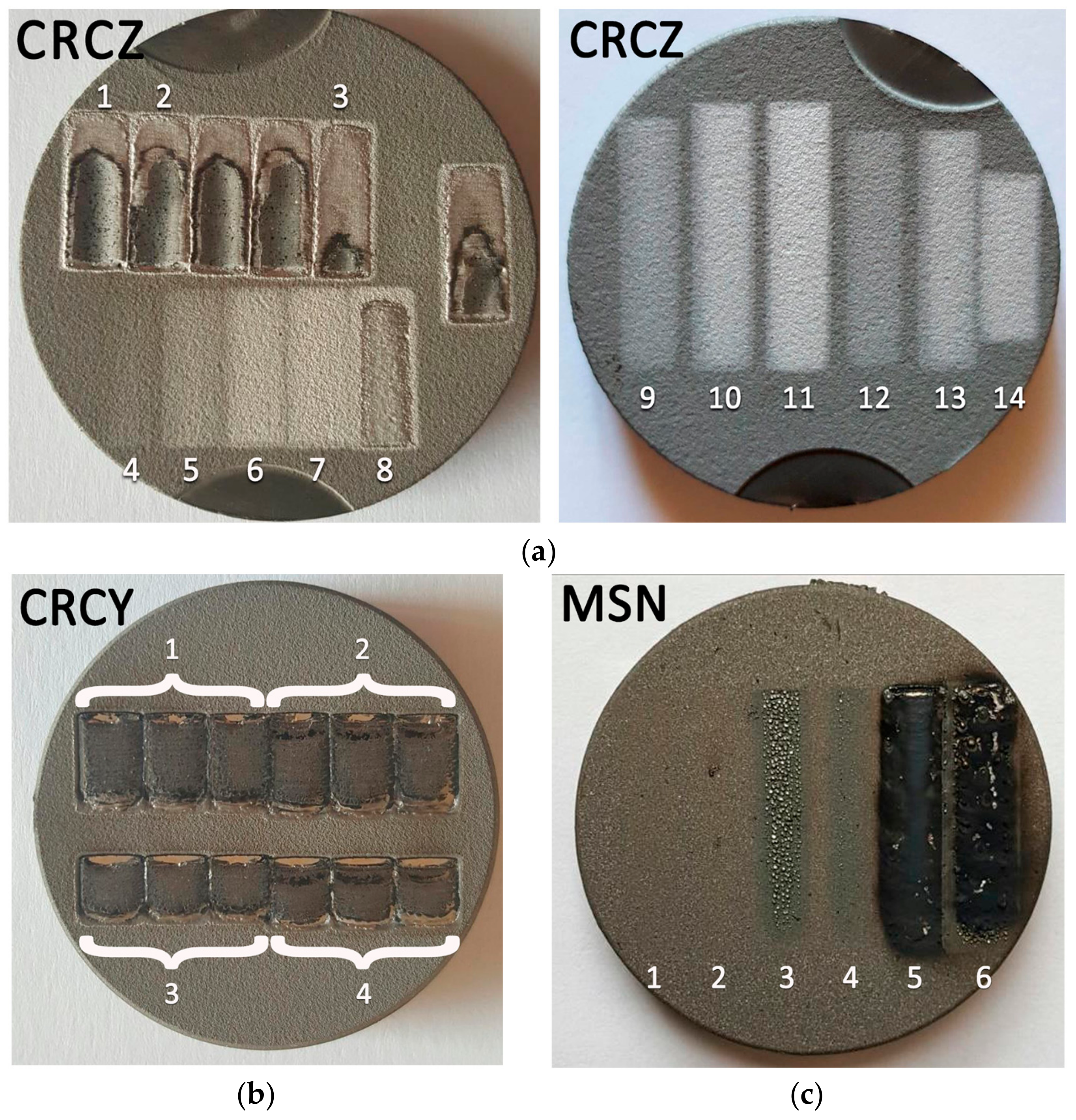
Figure 2.
Potential undesired effects of the laser interaction with the coating: (a) Vertical cracks; (b) incorporation of the assist gas inside the molten material and formation of the residual macro-porosity; (c) selective remelting or evaporation and recondensation of the low melting material in surface droplets; and (d) partial remelting of the coating with the formation of vertical cracks.

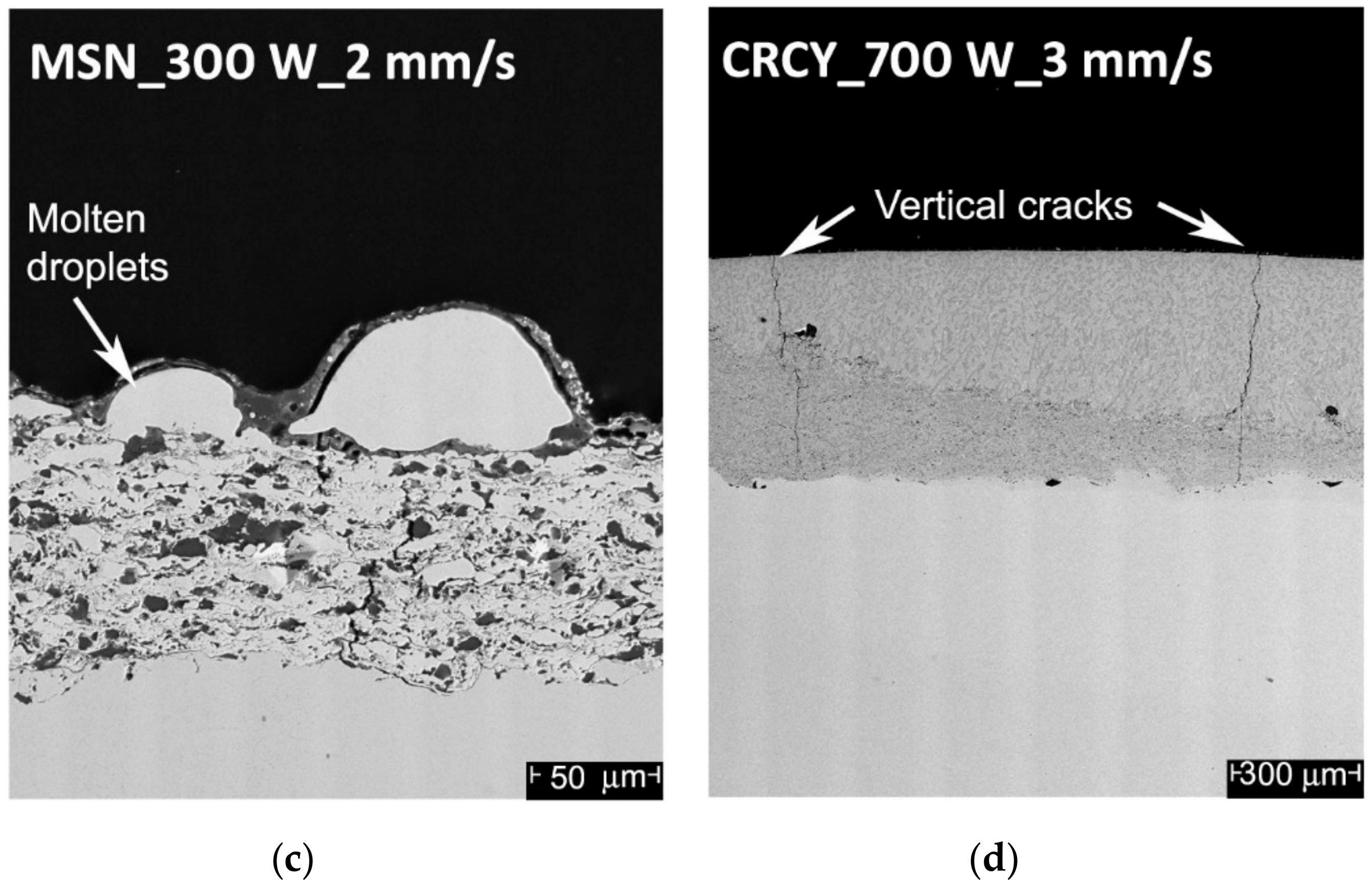
Figure 3.
Cross-sections of the CRCZ samples: (a) As-sprayed; (b) as-sprayed after 100 h of hot corrosion test; (c) as-sprayed after 200 h of hot corrosion test; (d) laser-treated; (e) laser-treated after 100 h of hot corrosion test; and (f) laser-treated after 200 h of hot corrosion test.
Figure 3.
Cross-sections of the CRCZ samples: (a) As-sprayed; (b) as-sprayed after 100 h of hot corrosion test; (c) as-sprayed after 200 h of hot corrosion test; (d) laser-treated; (e) laser-treated after 100 h of hot corrosion test; and (f) laser-treated after 200 h of hot corrosion test.

Figure 4.
Cross-sections of the CRCY samples: (a) As-sprayed; (b) as-sprayed after 100 h of hot corrosion test; (c) as-sprayed after 200 h of hot corrosion test; (d) laser-treated; (e) laser-treated after 100 h of hot corrosion test; and (f) laser-treated after 200 h of hot corrosion test.
Figure 4.
Cross-sections of the CRCY samples: (a) As-sprayed; (b) as-sprayed after 100 h of hot corrosion test; (c) as-sprayed after 200 h of hot corrosion test; (d) laser-treated; (e) laser-treated after 100 h of hot corrosion test; and (f) laser-treated after 200 h of hot corrosion test.

Figure 5.
Cross-sections of the MSN samples: (a) As-sprayed; (b) as-sprayed after 100 h of hot corrosion test; (c) as-sprayed after 200 h of hot corrosion test; (d) laser-treated; (e) laser-treated after 100 h of hot corrosion test; and (f) laser-treated after 200 h of hot corrosion test.
Figure 5.
Cross-sections of the MSN samples: (a) As-sprayed; (b) as-sprayed after 100 h of hot corrosion test; (c) as-sprayed after 200 h of hot corrosion test; (d) laser-treated; (e) laser-treated after 100 h of hot corrosion test; and (f) laser-treated after 200 h of hot corrosion test.
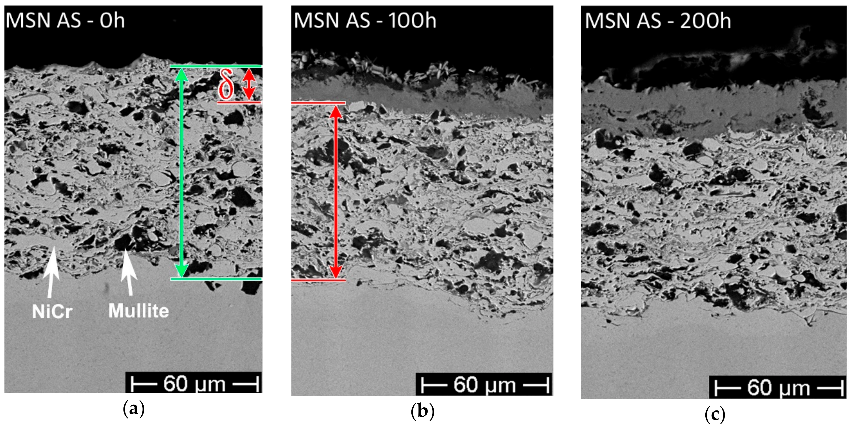
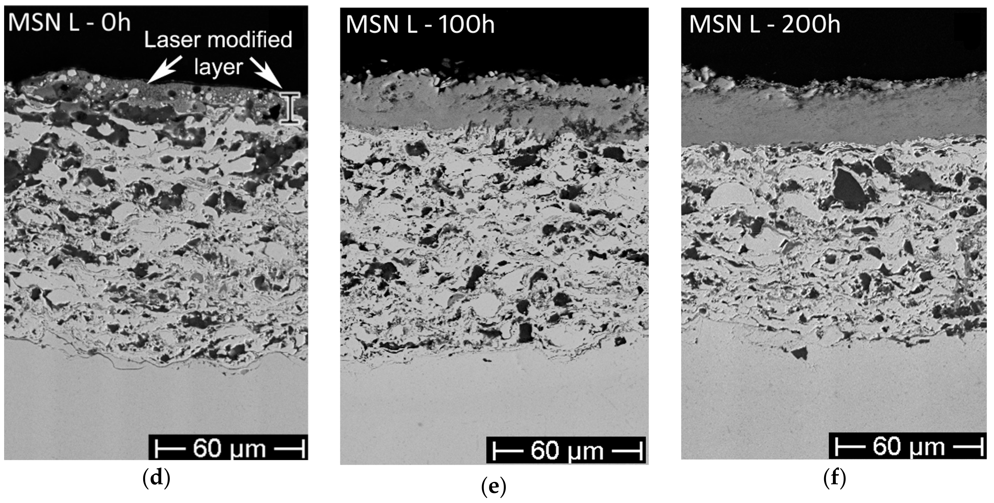
Figure 6.
Microhardness of the as-sprayed (AS) and laser-treated (L) samples measured on the cross-section (a) and the top surface (b) (error bars indicate +/− standard deviation).
Figure 6.
Microhardness of the as-sprayed (AS) and laser-treated (L) samples measured on the cross-section (a) and the top surface (b) (error bars indicate +/− standard deviation).

Figure 7.
Porosity of the as-sprayed (AS) and laser-treated (L) samples. (error bars indicate +/− standard deviation).
Figure 7.
Porosity of the as-sprayed (AS) and laser-treated (L) samples. (error bars indicate +/− standard deviation).
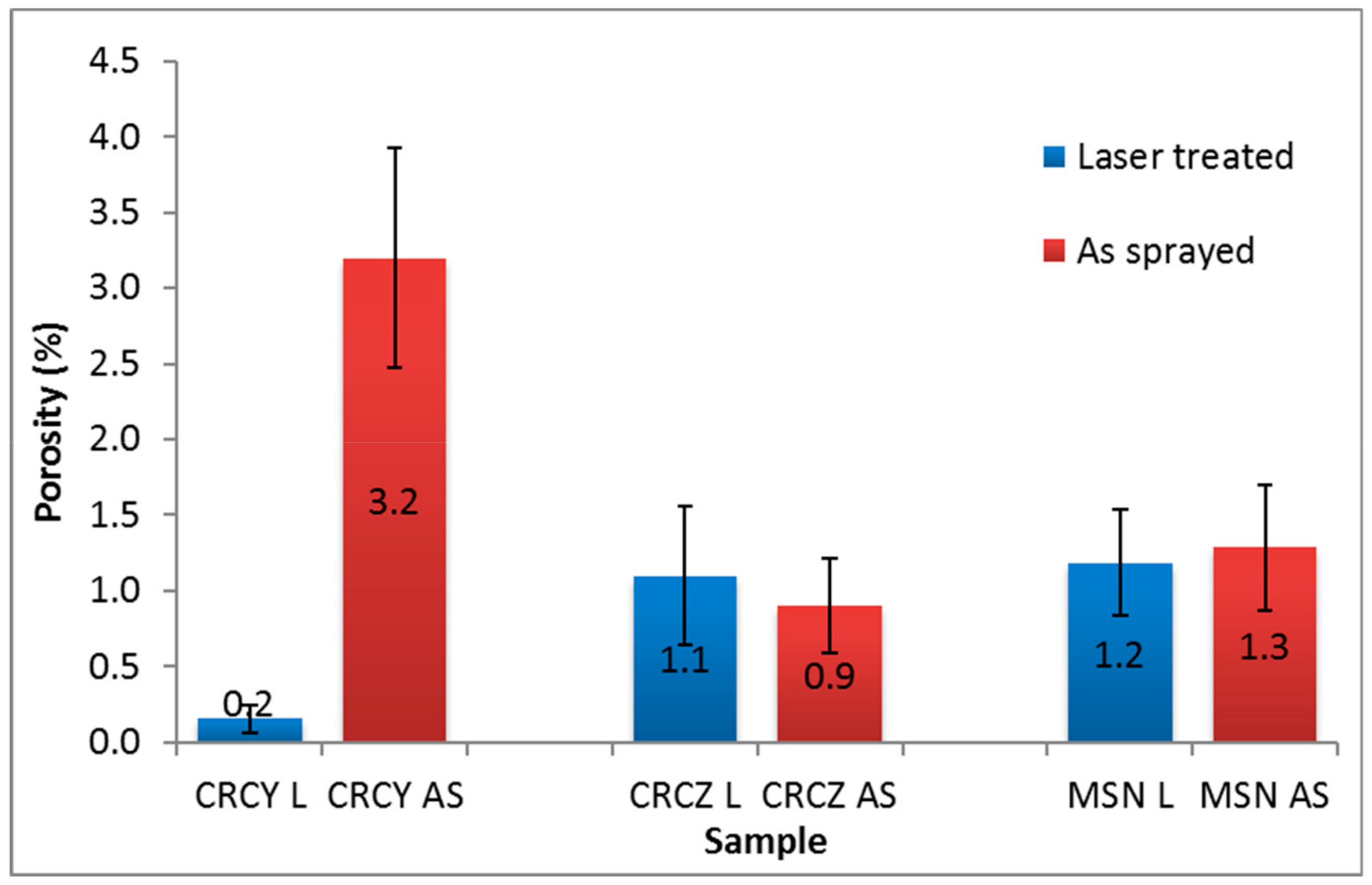
Figure 8.
XRD patterns for the CRCZ samples: AS—as sprayed (lower left); L—laser treated (upper left); AS-100 h—as sprayed, exposed for 100 h (lower right); and L-100h—laser treated, exposed for 100 h (upper right).
Figure 8.
XRD patterns for the CRCZ samples: AS—as sprayed (lower left); L—laser treated (upper left); AS-100 h—as sprayed, exposed for 100 h (lower right); and L-100h—laser treated, exposed for 100 h (upper right).
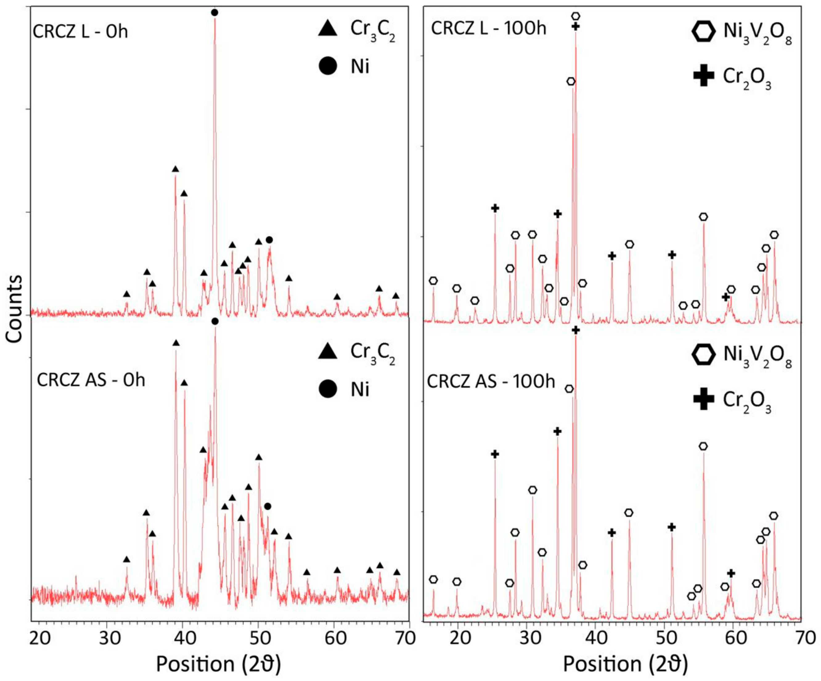
Figure 9.
XRD patterns for the CRCY samples: AS—as-sprayed (lower left); L—laser-treated (upper left); AS-100 h—as-sprayed, exposed for 100 h (lower right); L-100h—laser-treated, exposed for 100 h (upper right).
Figure 9.
XRD patterns for the CRCY samples: AS—as-sprayed (lower left); L—laser-treated (upper left); AS-100 h—as-sprayed, exposed for 100 h (lower right); L-100h—laser-treated, exposed for 100 h (upper right).

Figure 10.
XRD patterns for the MSN samples: AS—as-sprayed (lower left); L—laser-treated (upper left); AS-100 h—as-sprayed, exposed for 100 h (lower right); L-100h—laser-treated, exposed for 100 h (upper right).
Figure 10.
XRD patterns for the MSN samples: AS—as-sprayed (lower left); L—laser-treated (upper left); AS-100 h—as-sprayed, exposed for 100 h (lower right); L-100h—laser-treated, exposed for 100 h (upper right).

Figure 11.
EDS analysis of the corrosion scale for laser-treated samples, after 100 h of the corrosion test: (a) CRCZ; (b) CRCY; and (c) MSN.
Figure 11.
EDS analysis of the corrosion scale for laser-treated samples, after 100 h of the corrosion test: (a) CRCZ; (b) CRCY; and (c) MSN.

Figure 12.
Coating recession caused by hot corrosion exposure of increasing duration for the as-sprayed (AS, dashed line) and laser-treated (L, solid line) coatings.
Figure 12.
Coating recession caused by hot corrosion exposure of increasing duration for the as-sprayed (AS, dashed line) and laser-treated (L, solid line) coatings.


Table 1.
Designation and composition of powders used in the experimental activity.
| Name | Composition | Particle Size | Trade Name |
|---|---|---|---|
| CRCZ | 75 wt % Cr3C2 | −45 + 15 μm | Sulzer-WOKA 7302 |
| 25wt % Ni20Cr | |||
| CRCY | 75 wt % Cr3C2 | −45 + 15 μm | FST-K880.23 |
| 25wt % CoNiCrAlY (Co 9.50 Ni 7.50 Al 1.75 Y 0.20 C10 Cr bal.) | |||
| MSN | 10wt % nano-SiO2 | −53 + 20 μm (sieved) | Purposely produced |
| 30wt % mullite (3Al2O3-2SIO2) | |||
| 60wt % Ni20Cr |
Table 2.
Deposition parameters of high velocity oxy-fuel (HVOF) thermal-sprayed coatings.
| Composition | CRCZ | CRCY | MSN |
|---|---|---|---|
| Kerosene feed rate (gph) | 6.5 | 6.5 | 6 |
| O2 feed rate (scfh) | 2000 | 2000 | 1850 |
| Spray distance (mm) | 350 | 370 | 350 |
Table 3.
Laser treatment parameters for the Cr3C2–NiCr (CRCZ) coatings.
| Test No. | Power P (W) | Scan Rate V (mm/s) | Fluence H (J/mm2) |
|---|---|---|---|
| 1 | 800 | 4 | 53.08 |
| 2 | 800 | 3 | 70.77 |
| 3 | 700 | 3 | 61.92 |
| 4 | 200 | 2 | 26.54 |
| 5 | 300 | 2 | 39.81 |
| 6 | 400 | 2 | 53.08 |
| 7 | 500 | 2.5 | 52.08 |
| 8 | 600 | 2.5 | 63.69 |
| 9 | 300 | 3 | 26.54 |
| 10 | 400 | 4 | 26.54 |
| 11 | 500 | 5 | 26.54 |
| 12 | 300 | 4 | 20.51 |
| 13 | 400 | 5 | 20.51 |
| 14 | 500 | 6.5 | 20.51 |
Table 4.
Laser treatment parameters for the Cr3C2–CoNiCrAlY (CRCY) coatings.
| Test No. | Power P (W) | Scan Rate V (mm/s) | Fluence H (J/mm2) |
|---|---|---|---|
| 1 | 800 | 4 | 53.08 |
| 2 | 800 | 3 | 70.77 |
| 3 | 700 | 4 | 46.44 |
| 4 | 700 | 3 | 61.92 |
Table 5.
Laser treatment parameters for the mullite nano–silica–NiCr (MSN) coatings.
| Test No. | Power P (W) | Scan Rate V (mm/s) | Fluence H (J/mm2) |
|---|---|---|---|
| 1 | 200 | 2 | 26.54 |
| 2 | 200 | 4 | 13.27 |
| 3 | 300 | 2 | 39.81 |
| 4 | 300 | 4 | 20.51 |
| 5 | 400 | 2 | 53.08 |
| 6 | 400 | 4 | 26.54 |
© 2019 by the authors. Licensee MDPI, Basel, Switzerland. This article is an open access article distributed under the terms and conditions of the Creative Commons Attribution (CC BY) license (http://creativecommons.org/licenses/by/4.0/).
Share and Cite
MDPI and ACS Style
Baiamonte, L.; Bartuli, C.; Marra, F.; Gisario, A.; Pulci, G. Hot Corrosion Resistance of Laser-Sealed Thermal-Sprayed Cermet Coatings. Coatings 2019, 9, 347. https://doi.org/10.3390/coatings9060347
AMA Style
Baiamonte L, Bartuli C, Marra F, Gisario A, Pulci G. Hot Corrosion Resistance of Laser-Sealed Thermal-Sprayed Cermet Coatings. Coatings. 2019; 9(6):347. https://doi.org/10.3390/coatings9060347
Chicago/Turabian StyleBaiamonte, Lidia, Cecilia Bartuli, Francesco Marra, Annamaria Gisario, and Giovanni Pulci. 2019. "Hot Corrosion Resistance of Laser-Sealed Thermal-Sprayed Cermet Coatings" Coatings 9, no. 6: 347. https://doi.org/10.3390/coatings9060347
Note that from the first issue of 2016, this journal uses article numbers instead of page numbers. See further details here.