Effect of Wet Expansion Behavior on Polyimide Membrane Diffractive Lens

1
Institute of Optics and Electronics, Chinese Academy of Sciences, Chengdu 610209, China
2
University of Chinese Academy of Sciences, Beijing 100049, China
*
Author to whom correspondence should be addressed.
Coatings 2019, 9(9), 559; https://doi.org/10.3390/coatings9090559
Submission received: 6 August 2019
/
Revised: 20 August 2019
/
Accepted: 27 August 2019
/
Published: 2 September 2019
(This article belongs to the Special Issue Design, Manufacturing and Measurement of Optical Film Coatings)
Abstract
:Optical polyimide (PI) membrane is a potential substrate to fabricate a diffractive primary lens in large aperture space-borne telescope. In this paper, we investigated the wet expansion behavior of PI via a strain gauge method and measured the coefficient of wet expansion (CWE) of PI membrane supported by different fixtures. The CWE of silica-fixed, ring-fixed, and free state PI membrane were near zero, 5 ppm/%, and 10 ppm/% respectively. It is found that Fresnel zone lens (FZL), based on PI membrane with lower CWE, achieve a better imaging quality with smaller wave-front errors. The underlying mechanisms and methods to improve imaging quality of ring-fixed FZL are discussed. This work provides direction in fabricating a flexible membrane diffractive lens with applicable imaging quality.
1. Introduction
Polyimide (PI), with unique properties such as good space environmental adaptability, excellent chemical stability, and mechanical properties, has been widely applied in aerospace engineering, micro manufacturing, display panels industry, and so on [1]. A Fresnel zone lens (FZL) is fabricated by photolithography and subsequent etching process to form concentric rings in an optical substrate, and act as a diffractive lens. A traditional silica substrate-based FZLs are commercialized products, and different fabrication methods are available according to different technical specifications [2]. Large aperture FZLs, based on thin polyimide membranes, are promising primary lenses, used to build space-based telescopes, due to their light-weight and relaxed surface figure tolerance [3,4,5,6,7,8]. Wave-front error is the key parameter in evaluating the imaging quality of FZLs. The wave-front error of PI membrane, FZL, is theoretically influenced by substrate wave-front error and fabrication errors [9,10,11,12]. The key fabrication error for PI membrane FZL is structure position error (Δrm), as shown in Figure 1 [13,14,15]. Lawrence Livermore National Laboratory (LLNL) fabricated a PI membrane FZL and found that PI membrane expands and contracts substantially as humidity level of testing environment changes [16].
This behavior can distort the diffraction pattern, if the temperature and humidity change from laboratory to field, especially when the field is in space.
Previous studies of PI materials mostly focus on achieving good thermal and mechanical properties, tailoring coefficient of thermal expansion (CTE) and Young’s modulus [17,18]. Published papers on PI’s wet expansion behavior mainly look at the water absorbing mechanism and its electric application [19,20,21]. Blumentritt explored PI membrane’s anisotropy and dimensional stability and found that coefficient of wet expansion (CWE) varies in different directions, and anisotropy behavior was correlated to molecular orientation [22]. However, a traditional method that measures CWE of PI membrane, through an optical microscope, lacks precision and does not measure real-time data. Studies on the wave-front error of PI membrane FZL are rarely published. Further research needs to assess the way wet expansion behavior affects imaging quality of PI membrane FZL.
In this paper, we introduced a new method, based on strain gauges to online monitor wet expansion behavior of PI membranes, supported by different fixtures. We measured CWE of PI membrane, supported by ring-shape fixture under different stress. Then we fabricated two PI membrane FZLs, supported by a silica fixture and ring fixture, and measured corresponding wave-front errors. Finally, we discussed the influence of CWE on wave-front error and put forward possible approaches to eliminating the effect of wet expansion behavior on wave-front error.
2. Results and Discussion
Optical grade PI membranes were synthesized by 1,2,4,5-Benzenetetracarboxylic anhydride (PMDA) and 2,2’-Bistrifluoromethylbenzidine, and formed uniform membranes with 25 μm thickness and Φ80 mm aperture by multiple spin cast and imidization. We prepared three PI membrane samples, where the first was stretched and supported between two Φ80 mm aluminum ring-shape fixtures, as shown in Figure 2a below; the second was supported by silica substrate via vacuum contact, as shown in Figure 2b below and; the third was a free-state PI, without fixture. We also prepared a pure silica substrate as the fourth sample.
Commercial strain gauges BA120-3AA(11)-Q400 (Jingce Dianqi Co., Ltd., Hanzhong, China), with resistance value 119.9 ± 0.1 Ω and sensitivity coefficient 2.06% ± 1%, were glued on the sample surface, shown in Figure 2c. Strain data was recorded and processed by DH3820 system with 2 Hz sampling frequency. Then we placed all four samples in 5% tetra methyl ammonium hydroxide (TMAH) solution at room temperature for more than 5 h to simulate development process.
The results are shown in the Figure 3 below, in which the red line refers to sample in free state, the green line refers to sample supported by ring-shape fixture, the purple line stands for sample supported by silica substrate, and the blue line represents pure silica substrate. Notably, silica-fixed PI achieves near zero CWE similar to silica substrate. The reason is that PI membrane and silica substrate formed strong adhesive force through vacuum contact. We also found that CWE of ring-fixed PI is smaller than that of free state PI.
Accurate CWEs of PI membrane, supported by ring-fixture with different initial stress, were measured through humidity program, as shown in Figure 4 below. Humidity was controlled by HUT720P environmental test chamber (Hardy Technology Co., Ltd., Chongqing, China), with nominal 10%–98% range.
CWE is calculated by Equation (1) in which ΔL/L stands for strain and ΔH stands for humidity change:
The results are shown in the Figure 5 below, where the red line refers to the sample in free-state (initial stress = 0 MPa), the blue line refers to sample under 5 MPa initial stress, and the black line refers to sample under 10 MPa initial stress.
It was found that once humidity increases, the ring-fixed PI membrane expands less than 50% of free state PI membrane, and the corresponding CWE is around 5 ppm/%. We also notice that humidity from 30% to 60% initial stress of ring-fixed PI membrane does not influence CWE and humidity from 60% to 90% larger initial stress corresponds to lower CWE. The possible reason is that, when humidity increases from 60% to 90%, the stress of PI membrane continues to decrease, and at some point, the sample under 5 MPa initial stress becomes free state, while the sample under 10 MPa initial stress still keeps stretched. The underlying mechanism is that, once PI has expansion trend upon absorbing water, the ring relaxes a little thus exerting lower stress to PI leading to a shrinkage trend. The final impact is that the real expansion is lower than the free-state PI, as illustrated in Figure 6 below. The black line refers to expansion trend and its slope equals CWE of free state PI membrane. The red line refers to the shrinkage trend, and its slope is the decreased strain divided by increased humidity.
Because the membrane and ring-fixture are under static equilibrium, Equation (2) is established; on the left side m0 is original size of PI membrane under humidity H1, m1 is stretched size of PI under humidity H1, Em and Am refer to Young’s modulus and cross sectional area of PI and remain unchanged with humidity. On the right side k0 is original size of ring fixture, k1 is compressed size of ring fixture under humidity H1, Ek and Ak refer to Young’s modulus and cross sectional area of ring fixture and remain unchanged with humidity:
Assume that humidity increases from H1 to H2 (H2 > H1), a new static equilibrium is established, as expressed by Equation (3), where on the left side m2, is the stretched size of PI under humidity H2, m’0 is original size of PI membrane under humidity H2. On the right side k2 is the compressed size of ring fixture under humidity H2. It is obvious that the sizes of PI and fixture have relations shown in Equations (4)–(7).
The right side of Equation (3) is smaller than the right side of Equation (2) because (k0 − k1) > (k0 − k2), whereas on the left side m2 > m1, thus, to match the Equations, there must be m’0 > m0. It is reasonable because wet expansion causes stress release, and m’0 and m0 follow Equation (8), by which ΔH equals (H2 − H1) and CWE is of free state PI. We can also transform Equation (2) to Equation (9):
Then we can derive a relationship between m2 and m1 in Equation (10). α and β are used for simplification. Because α > 1, thus m2/m1 < α and Equation (11) can be derived:
In Equation (11) CWE’ is a ring-fixed PI membrane and there must be CWE’ < CWE. This explains why CWE of ring-fixed PI is less than that of free state PI.
Then, FZLs were fabricated on ring-fixed, with 10 MPa initial stress, and silica-fixed PI membranes, by contact photolithography and subsequent reactive ion etching. Fabrication process is shown in Figure 7 below and detailed photolithography and etching process parameters are listed in Table 1 below.
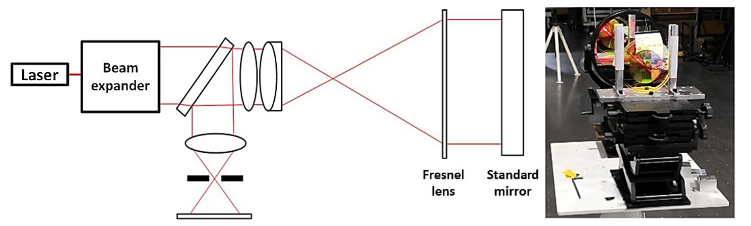
Finally, the wave-front errors of fabricated FZLs were measured. The schematic of wave-front error measurement system is shown in the Figure 8 below with site photo. Interferometer and high precision standard mirror were applied to form a self-collimating light path, the PI membrane lens was placed between interferometer and a standard mirror, where the focal plane of interferometer and of Fresnel lens overlapped with each other.
Wave-front error of the PI membrane lens is sensitive to the position accuracy of Fresnel structures [23]. Our designed F# is 10 and maximum acceptable wave-front error is λ/20 in root mean square (RMS). The optical wave-front of PI membrane and silica substrate is less than λ/30 in RMS. The results are shown in Figure 9 below, where silica-fixed PI lens achieved good imaging quality with wave-front error smaller than λ/30 in RMS, and ring-fixed PI lens acquired wave-front error about λ/3 in RMS. The result demonstrates that silica-fixed PI membrane with near zero CWE ensures structure position accuracy of PI membrane FZL. The result also reveals that ring-fixed PI membrane with CWE around 5 ppm/% experienced considerable deformation and caused saddle-shaped astigmatism, as shown in Figure 9b, which indicates anisotropic expansion in plane.
Moreover, if we lower the temperature of the ring fixture when humidity increases, it is possible to eliminate deformation and achieve good imaging quality. Because in Equation (3), if temperature of ring fixture is lowered, the original size of ring decreases from k0 to k’0 to balance the Equation. Similarly, we can increase the temperature of the ring fixture when humidity decreases. Therefore, if initial stress of ring-fixed PI membrane is isotropic and sufficient, it is possible to achieve good imaging quality by controlling the temperature of the ring fixture.
3. Conclusions
In conclusion, we introduced a method based on strain gauge to study the wet expansion behaviors of PI membranes, supported by different fixture, and found that silica-fixed PI membrane achieves near zero CWE and FZL, based on silica-fixed PI achieves good imaging quality. We also measured CWE of ring-fixed PI under different stress and discussed the underlying mechanisms. Controlling the ring fixture temperature is expected to eliminate membrane deformation brought by humidity change and achieve good imaging quality for ring-fixed PI membrane FZL.
Author Contributions
Conceptualization, G.G.; Methodology, D.M.; Resources, D.M.; Data Curation, G.G.; Writing—Original Draft Preparation, G.G.; Writing—Review and Editing, G.G.; Supervision, C.G.; Project Administration, B.F.; Funding Acquisition, B.F.
Funding
This work was supported by the National Key R & D Program of China (No. 2016YFB0500200) and the Key Program of Chinese Academy of Sciences (No. YA16K010).
Conflicts of Interest
The authors declare no conflict of interest.
References
- Liaw, D.J.; Wang, K.L.; Huang, Y.C.; Lee, K.R.; Lai, J.Y.; Ha, C.S. Advanced polyimide materials: Syntheses, physical properties and applications. Prog. Polym. Sci. 2012, 37, 907–974. [Google Scholar] [CrossRef]
- Atcheson, P.D.; Stewart, C.; Domber, J.; Whiteaker, K.; Cole, J.; Spuhler, P.; Seltzer, A.; Britten, J.A.; Dixit, S.N.; Farmer, B.; et al. MOIRE: Initial demonstration of a transmissive diffractive membrane optic for large light weight optical telescopes. In Proceedings of the SPIE Astronomical Telescopes + Instrumentation—Space Telescopes and Instrumentation 2012: Optical, Infrared, and Millimeter Wave, Amsterdam, The Netherlands, 21 September 2012; Volume 8442, p. 844221. [Google Scholar] [CrossRef]
- Barton, I.M.; Britten, J.A.; Dixit, S.N.; Summers, L.J.; Thomas, I.M.; Rushford, M.C.; Lu, K.; Hyde, R.A.; Perry, M.D. Fabrication of large-aperture lightweight diffractive lenses for use in space. Appl. Opt. 2001, 40, 447–451. [Google Scholar] [CrossRef] [PubMed]
- Domber, J.L.; Atcheson, P.D.; Kommers, J. MOIRE: Ground test bed results for a large membrane telescope. In Proceedings of the Spacecraft Structures Conference, National Harbor, Maryland, 13–17 January 2014. [Google Scholar] [CrossRef]
- Atcheson, P.; Domber, J.; Whiteaker, K.; Britten, J.A.; Dixit, S.N.; Farmer, B. MOIRE: Ground demonstration of a large aperture diffractive transmissive telescope. In Proceedings of the SPIEA Stronomical Telescopes + Instrumentation—Space Telescopes and Instrumentation 2014: Optical, Infrared, and Millimeter Wave, Montréal, QC, Canada, 28 August 2014; Volume 9143, p. 91431W. [Google Scholar] [CrossRef]
- Rahlves, M.; Rezem, M.; Boroz, K.; Schlangen, S.; Reithmeier, E.; Roth, B. Flexible, fast, and low-cost production process for polymer based diffractive optics. Opt. Express 2015, 23, 3614–3622. [Google Scholar] [CrossRef] [PubMed]
- Feltz, J.C. Development of the modulation transfer function and contrast transfer function for discrete systems, particularly charge-coupled devices [also Comment 35(7), 2105-2106 (July 1996)]. Opt. Eng. 1990, 29, 893–905. [Google Scholar] [CrossRef]
- Meinel, A.B.; Meinel, M.P. Large sparse-aperture space optical systems. Opt. Eng. 2002, 41, 1983–1994. [Google Scholar] [CrossRef]
- Britten, J.A.; Dixit, S.N.; DeBruyckere, M.; Steadfast, D.; Hackett, J.; Farmer, B.; Poe, G.; Patrick, B.; Atcheson, P.D.; Domber, J.L.; et al. Large-aperture fast multilevel Fresnel zone lenses in glass and ultrathin polymer films for visible and near-infrared imaging applications. Appl. Opt. 2014, 53, 2312–2316. [Google Scholar] [CrossRef] [PubMed]
- Zhang, Y.; Jiao, J.C.; Wang, B.H.; Jin, J.G.; Su, Y. Transmissive diffractive membrane optic for large aperture lightweight optical telescope. In Proceedings of the International Conference on Optical Instruments and Technology 2015, Beijing, China, 5 August 2015; Volume 9622, p. 96220G. [Google Scholar]
- Margit, F.; Kuhlow, B.; Pawlowski, E. Effect of fabrication errors on multilevel Fresnel zone lenses. Opt. Eng. 1994, 33, 1229–1236. [Google Scholar] [CrossRef]
- Wang, S.; Yang, W.; Wu, S.B. Effect of fabrication errors on binary optical element imaging quality. In Proceedings of the International Symposium on Photoelectronic Detection and Imaging 2013: Micro/Nano Optical Imaging Technologies and Applications, Beijing, China, 23 August 2013; Volume 8911, p. 891100. [Google Scholar] [CrossRef]
- Stern, M.B.; Holz, M.; Medeiros, S.S.; Knowlden, R.E. Fabricating binary optics: Process variables critical to optical efficiency. J. Vac. Sci. Technol. B 1991, 9, 3117–3121. [Google Scholar] [CrossRef]
- Jin, G.F.; Yan, Y.B.; Wu, M.X. Binary Optics; National Defence Industry Press: Beijing, China, 1998; pp. 192–211. (In Chinese) [Google Scholar]
- Wang, R.; Zhang, Z.; Guo, C.; Xue, D.; Zhang, X. Effects of fabrication errors on diffraction efficiency for a diffractive membrane. Chin. Opt. Lett. 2016, 14, 120501. [Google Scholar] [CrossRef]
- Copp, T.; Domber, J.L.; Atcheson, P.D.; Tandy, W.D.; Kommers, J.; Farmer, B. MOIRE: Membrane material property characterizations, testing and lessons learned. In Proceedings of the Spacecraft Structures Conference, National Harbor, Maryland, 13–17 January 2014. [Google Scholar] [CrossRef]
- Low and Zero CTE Polyimides. Available online: http://nexolvematerials.com/nexolve-products/low-and-zero-cte-polyimides (accessed on 10 March 2016).
- Tsukada, Y. Ultra low CTE (0 PPM/C) polyimide film and its potential application. In Proceedings of the 2010 34th IEEE/CPMT International Electronic Manufacturing Technology Symposium (IEMT), Melaka, Malaysia, 30 November–2 December 2010. [Google Scholar] [CrossRef]
- Huang, X.F.; Sheng, D.R.; Cen, K.F.; Zhou, H. Low-cost relative humidity sensor based on thermoplastic polyimide-coated fiber Bragg grating. Sens. Actuators B Chem. 2007, 127, 518–524. [Google Scholar] [CrossRef]
- Zou, D.S.; Wang, D.F. A new type of polyimide capacitive humidity sensor. Instrum. Technol. Sens. 1992, 1, 6–7. (In Chinese) [Google Scholar]
- Matsuguchi, M.; Kuroiwa, T.; Miyagishi, T.; Suzuki, S.; Ogura, T.; Sakaia, Y. Stability and reliability of capacitive type relative humidity sensors using crosslinked polyimide films. Sens. Actuators B 1998, 52, 53–57. [Google Scholar] [CrossRef]
- Blumentritt, B.F. Anisotropy and dimensional stability of polyimide films. Polym. Eng. Sci. 1978, 18, 1216–1219. [Google Scholar] [CrossRef]
- Wang, L.H.; Wu, S.B.; Yang, W. Analysis of stitched fresnel lens segmented mirrors miss-adjustment error. Acta Opt. Sin. 2016, 36, 0712002. (In Chinese) [Google Scholar]
Figure 1.
Schematic of Polyimide (PI) membrane Fresnel zone lens (FZL).

Figure 2.
PI membrane supported by ring-shape fixture (a), PI membrane supported by silica substrate (b) and strain gauge glued on sample surface (c).
Figure 2.
PI membrane supported by ring-shape fixture (a), PI membrane supported by silica substrate (b) and strain gauge glued on sample surface (c).

Figure 3.
PI membrane’s response to water absorption under different fixing states.

Figure 4.
Humidity program of environmental test chamber.

Figure 5.
Effect of initial stress on wet expansion behavior of ring-fixed PI membrane.

Figure 6.
The strain-humidity relationship of ring-fixed PI membrane.

Figure 7.
Process flow of FZL fabrication on ring-fixed PI membrane (a) and silica-fixed PI membrane (b).
Figure 7.
Process flow of FZL fabrication on ring-fixed PI membrane (a) and silica-fixed PI membrane (b).

Figure 8.
The schematic of wave-front error measurement system and site photo.

Figure 9.
The wave-front error of silica-fixed (a) and ring-fixed (b) PI membrane FZLs.


Table 1.
Detailed process parameters.
| Process Steps | Parameters | Humidity |
|---|---|---|
| Photoresist | AZ3100, 2000 rpm, 60 s | 40%–60% |
| Soft bake | 100 °C, 5 min | 10%–20% |
| Exposure | 4.5 mW/cm2, 20 s | 40%–60% |
| Development | 5% TMAH, 30 s | 100% |
| Hard bake | 120 °C, 5 min | 10%–20% |
| Dry etching | O2, 30 sccm, 1 Pa, 100 W, 5 min | 0% |
© 2019 by the authors. Licensee MDPI, Basel, Switzerland. This article is an open access article distributed under the terms and conditions of the Creative Commons Attribution (CC BY) license (http://creativecommons.org/licenses/by/4.0/).
Share and Cite
MDPI and ACS Style
Gao, G.; Mao, D.; Fan, B.; Guan, C. Effect of Wet Expansion Behavior on Polyimide Membrane Diffractive Lens. Coatings 2019, 9, 559. https://doi.org/10.3390/coatings9090559
AMA Style
Gao G, Mao D, Fan B, Guan C. Effect of Wet Expansion Behavior on Polyimide Membrane Diffractive Lens. Coatings. 2019; 9(9):559. https://doi.org/10.3390/coatings9090559
Chicago/Turabian StyleGao, Guohan, Danbo Mao, Bin Fan, and Chunlin Guan. 2019. "Effect of Wet Expansion Behavior on Polyimide Membrane Diffractive Lens" Coatings 9, no. 9: 559. https://doi.org/10.3390/coatings9090559
Note that from the first issue of 2016, this journal uses article numbers instead of page numbers. See further details here.