

Advanced Embedded System Modeling and Simulation in an Open Source RISC-V Virtual Prototype †

1
Cyber-Physical Systems, DFKI GmbH, 28359 Bremen, Germany
2
Institute of Computer Science, University of Bremen, 28359 Bremen, Germany
*
Author to whom correspondence should be addressed.
†
This paper is an extended version of our paper published in GLSVLSI 2022, Irvine, CA, USA.
J. Low Power Electron. Appl. 2022, 12(4), 52; https://doi.org/10.3390/jlpea12040052
Submission received: 1 September 2022
/
Revised: 22 September 2022
/
Accepted: 25 September 2022
/
Published: 29 September 2022
(This article belongs to the Special Issue RISC-V Architectures and Systems: Hardware and Software Perspectives)
Abstract
:RISC-V is a modern Instruction Set Architecture (ISA) that, by its open nature in combination with a clean and modular design, has enormous potential to become a game changer in the Internet of Things (IoT) era. Recently, SystemC-based Virtual Prototypes (VPs) have been introduced into the RISC-V ecosystem to lay the foundation for advanced industry-proven system-level use-cases. However, VP-driven environment modeling and interaction have mostly been neglected in the RISC-V context. In this paper, we propose such an extension to broaden the application domain for virtual prototyping in the RISC-V context. As a foundation, we built upon the open source RISC-V VP available at GitHub. For a visualization of the environment purposes, we designed a Graphical User Interface (GUI) and designed appropriate libraries to offer hardware communication interfaces such as GPIO and SPI from the VP to an interactive environment model. Our approach is designed to be integrated with SystemC-based VPs that leverage a Transaction-Level Modeling (TLM) communication system to prefer a speed-optimized simulation. To show the practicability of an environment model, we provide a set of building blocks such as buttons, LEDs and an OLED display and configured them in two demonstration environments. Moreover, for rapid prototyping purposes, we provide a modeling layer that leverages the dynamic Lua scripting language to design components and integrate them with the VP-based simulation. Our evaluation with two different case-studies demonstrates the applicability of our approach in building virtual environments effectively and correctly when matching the real physical systems. To advance the RISC-V community and stimulate further research, we provide our extended VP platform with the environment configuration and visualization toolbox, as well as both case-studies as open source on GitHub.
1. Introduction
RISC-V [1,2] is a modern Instruction Set Architecture (ISA) that has gained significant momentum in recent years. A key factor that drives the RISC-V success story is its free and open nature, combined with a lightweight and modular architecture. Moreover, RISC-V is designed from the ground up to enable the integration of custom instruction set extensions in order to build highly application-specific solutions. These properties push the adoption of RISC-V and strengthen its potential to become a game changer in the Internet of Things (IoT) era. As such, great interest can be observed around RISC-V in industry and academia.
In line with RISC-V’s popularity, the extensive RISC-V ecosystem is continuously growing to include a broad set of software and hardware development tools and library. Recently, virtual prototyping solutions have been introduced into the RISC-V ecosystem to lay the foundation for advanced system-level use-cases in the RISC-V context. A Virtual Prototype (VP) is essentially an abstract model of the entire hardware platform and enables early software development in the design flow. An industry-proven standard to create VPs is using the SystemC language in combination with the Transaction-Level Modeling (TLM) style for modeling abstract communication interfaces [3]. A key property of VPs is their binary compatibility with the hardware platform, i.e., from the software perspective, the VP provides the same interface as the hardware platform and hence the software can be executed unmodified on the VP and hardware. Besides a functional validation, VPs also enable design space exploration by evaluating different design decisions early in the design flow.
The RISC-V VP is a representative, advanced open source VP tailored for RISC-V and available at GitHub [4], and has been described in [5]. It provides an extensive feature set, such as support for the 32 and 64 bit RISC-V ISA, with all standard instruction set extensions, several operating systems (such as Zephyr and Linux), advanced debugging capabilities and configurations to create different platforms, such as the HiFive1 board from SiFive [6]. The main benefit of the RISC-V VP is, however, the ease of its ability to expand from custom RISC-V instructions with dynamic dataflow analysis extensions [7] to a symbolic execution engine [8]. However, representative of other VPs in the RISC-V context, the RISC-V VP is missing an effective methodology used to design and integrate models that capture the interaction of the VP with the environment, such as other components on a PCB besides the processor chip.
In this paper, we propose such an extension to broaden the application domain for virtual prototyping in the RISC-V context. We provide a set of building blocks for the environment, which includes buttons, LEDs and a display. The main idea of our approach is to separate the hardware model from the world behavior (see Figure 1, VP Environment vs. RISC-V VP). This allows for the parallel development of software and hardware within the intended environment, speeding up the design process. For visualization of the environment, we designed a Graphical User Interface (GUI) using the Qt C++ library. To ease the environment setup, we provide a configuration-file-based approach that enables the designer to specify the desired components and appropriate connections to the VP in a simple way. The communication channel between the VP and environment GUI is established through a TCP connection (which also enables us to distribute the simulation to different computers e.g., a simulation server and a user’s desktop PC). We designed appropriate libraries to transfer several hardware communication interfaces, such as GPIO, SPI or CAN (via SPI), on top of the TCP channel. This allows us to transparently map these interfaces between the VP, which models the SoC, and the environment GUI, which displays and simulates the behavior of external components. Furthermore, the communication was optimized to avoid performance impacts on the VP simulation. Our approach was designed to be integrated with SystemC-based VPs that leverage a Transaction Level Modeling (TLM) communication system. In addition, our setup provides the foundation to even attach external real hardware components to perform a VP-driven hardware-in-the-loop simulation. To facilitate the environment model design, we provide a set of building blocks, such as buttons, LEDs and an OLED display. Moreover, for rapid prototyping purposes, we provide a modeling layer that leverages the dynamic Lua scripting language to design components and integrate them with the VP-based simulation. For evaluation purposes, we provide two case-studies with different virtual environments. In all case-studies, we used the RISC-V VP in the HiFive1 configuration, which is a model of the RISC-V HiFive1 board from SiFive [6]. Besides the two virtual environments, we also built the corresponding two real physical systems. We can observe that both the virtual and physical systems behave identically in these case-studies, which demonstrates that our approach provides suitable virtual models to enable early software development in the design flow. We also believe that the combined VP platform can be very beneficial for education purposes in lectures and also for further research projects.
Besides our own positive experience in using our VP platform for teaching lectures on system-level design and virtual prototyping, we are also already aware of an other academic group that has leveraged our RISC-V VP infrastructure for teaching an embedded systems lecture with laboratory sessions in the RISC-V context [9]. This further underlines the applicability of our VP platform with environment modeling capabilities for educational purposes. To further spread its adoption, we provide the VP platform with the environment interaction in combination with the case-studies as open source [4].
1.1. Paper Structure
This journal paper includes and extends published material from our previous conference paper [10]. We start by outlining the new contributions of this paper in the next paragraph. Then, we continue with a discussion of related work (Section 2) and provide relevant background information (Section 3). Next, we present the VP-driven environment modeling methodology, including the communication interfaces and configuration features, in more detail (Section 4). We follow up with our rapid prototyping approach using the dynamic Lua scripting language (Section 5). Then, we present our modeling case-studies with two different environment configurations (Section 6.1). Afterwards, we describe the results of our performance evaluation (Section 6.2). Finally, after a discussion on future work (Section 7), we conclude the paper (Section 8).
1.2. New Contributions
In comparison to our previous conference paper [10], we have implemented a significant set of extensions to our VP-driven environment modeling platform. The extensions include a new rapid prototyping approach for modeling components using the dynamic Lua scripting language with a set of dedicated interfaces to enable an integration with a SystemC-based simulation, updated communication protocols to enable a better performance and more reliable communication and an updated set of component building blocks to speed up the development process of new environments. We also updated and extended the related work, preliminaries and future work sections to reflect the new developments, as well as provided a more detailed and reformulated description of the VP-driven environment modeling and added case-studies in the experiment section. To accommodate these new contributions, the paper has also undergone significant editorial changes.
The complete implementation of our VP-driven environment modeling platform, including all new extensions and case-studies, is available open source on GitHub.
2. Related Work
The extensive ecosystem of RISC-V comprises several simulators that differ in their implementation technique and intended purpose in order to cover different use-cases. SPIKE is the reference simulator that is mainly designed for pure CPU simulations with a basic set of peripherals [11]. RV8 is a high-speed simulator that employs just-in-time compilation techniques to boost the execution performance, but also mainly covers pure CPU simulations [12]. R2VM also targets CPU simulations by utilizing binary translation techniques [13]. It can switch between fast and accurate simulations in order to cover different use-cases. QEMU enables a full system simulation that covers a complete platform and employs advanced binary-level optimization techniques to achieve a high performance [14]. Building on that, [15] proposed an approach to efficiently simulate Translation Lookaside Buffer (TLB) behaviors in a QEMU setting. Gem5 is also a full-system simulator that puts a stronger emphasis on architectural exploration aspects, but has a significantly reduced performance as a trade-off [16,17]. Going beyond that, the Renode simulation system supports multi-node networks of embedded systems in a distributed simulation [18]. Recently, SystemC-based processor simulation solutions have been introduced into the RISC-V ecosystem as well. Besides the RISC-V VP, which we have covered in the introduction, viable alternatives are the DBT-RISE [19] framework, ETISS [20,21] and the RISC-V-TLM [22] instruction set simulator, which are also designed with a SystemC integration in mind and provide RISC-V support. However, they lack a way to model external devices, e.g., via SPI or GPIO. Regarding DBT-RISE, an example VP platform that integrates an RISC-V instruction set simulator and is implemented in SystemC TLM is provided [23]. Another SystemC TLM simulator for RISC-V is RISC-V-TLM [22], which is currently under active development to increase the supported core feature set. A recent approach that has built upon the RISC-V VP is a proposed visualization of the internal VP execution state for debugging purposes [24]. It offers a live view into the execution state of the SystemC peripherals but lacks an interactive modeling platform for the environment interaction. However, the freely available VP-based frameworks for RISC-V are currently missing an effective methodology used to design and integrate configurable environment models with extensive graphical capabilities. Advanced environment modeling capabilities in a configurable framework with extensive graphical capabilities, as proposed in this paper, is, to the best of our knowledge, not yet available using any of the open RISC-V virtual prototyping approaches. Finally, there are commercial VP tools such as Synopsys Virtualizer [25] that might support RISC-V in combination with extensive environment modeling capabilities, but their implementation is proprietary.
Looking beyond RISC-V, existing simulators such as simavr [26] and PICSimLab [27] (using simavr in the background) can be cycle-accurate but are limited to a certain family of AVR processors, and are fairly computationally expensive. In contrast to our approach, which offers an interface to a SystemC VP and hence is able to incorporate custom in-house chips and IPs, these simulators are not designed with advanced industry-proven SystemC-based virtual prototyping in mind.
3. Preliminaries
In this section, we review background information on SystemC TLM and virtual prototyping (Section 3.1) and embedded systems, with a focus on components and interfaces (Section 3.2).
3.1. SystemC TLM and Virtual Prototyping
SystemC [28] is a hardware modeling framework, designed as a C++ library, that is widely adopted in the industry. It offers a C/C++ style modeling framework with varying degrees of timing accuracy at the benefit of simulation speed. The structure of a SystemC design is described with ports and modules, whereas the behaviour is modeled in processes that are triggered by events. The execution of a process is non-preemptive, i.e., it uses co-operative user-space scheduling for the processes of each module. This means that a process, once started, runs indefinitely until it either yields (wait()) or terminates forever (return). The process will be woken up when an event in its static sensitivity list triggers (e.g., a clock edge), or it can wait for a dynamic sc_event. This event may be triggered immediately or with a delay by, e.g., an asynchronous task, calling event.notify(delay). Communication between SystemC modules can be abstracted using the TLM standard [29] at the cost of timing accuracy, but with significant improvements in simulation speed, i.e., up to a factor of 1000 in comparison to the RTL simulation. Especially in bus-like memory mapped communication networks, skipping interconnect procedures and abstracting bus protocols greatly reduces the execution time. A transaction object essentially consists of a command (e.g., read/write) and the data (payload) to be transmitted. Transactions are routed based on their address from an initiator to a target socket, which is all defined in the SystemC TLM-2.0 standard, and allow for very fast interactions between modules. Optionally, a transaction can be associated with a delay (modeled as sc_time data structure), which denotes the execution time of the transaction and allows us to obtain a more accurate overall simulation time estimation. Instead of taking the whole route through the VP, interactions can be initiated directly to a target port. These transactions can either read or write at a specified address carrying a generic payload along with a cumulative delay, and may return either OK or ERROR. This delay is increased by every model passing the transaction and is added to a global quantum afterward. The global quantum tracks the time difference that a transaction “jumped" in contrast to the actual simulated time. If this difference is bigger than the maximum allowed time, SystemC will initiate a global synchronization. This allows for a fine control over the trade-off between simulation speed and accuracy.
SystemC TLM is a de facto standard used to build advanced VPs that offer efficient and extendable interfaces to model a wide range of different embedded systems early in the design flow.
3.2. Embedded Systems: Components and Interfaces
The General Purpose Input/Output (GPIO) module is, in most embedded devices, the interface to the outside world. It drives the physical pins of the chip or interprets applied voltage as logic inputs, but can also be configured as an interface to other on-chip peripherals. These peripherals depend on the instance of the System-on-Chip (SoC) and may include digital data interfaces (e.g., Universal Asynchronous Receiver–Transmitter (UART), Serial Peripheral Interface (SPI)), Analog-to-Digital Converters (ADCs) or timer-controlled Pulse-Width-Modulated (PWM) outputs. Aside from active polling, the CPU may also enable hardware interrupts that trigger when, e.g., the input state of a pin changes. This way, the CPU may work on other threads and only be notified via the Platform Local Interrupt Controller (PLIC) on a state change, initiated by the GPIO module.
4. VP-Driven Environment Modeling
In this section, we present our proposed approach. We first introduce the main software architecture components of the modified RISC-V VP and our new VP environment GUI (Section 4.1). Then, in Section 4.2, we look in more detail at the communication between SystemC modules and the new GPIO server; and between the two executables. Lastly, in Section 4.3, we show the details of our environment modeling GUI and the currently available, placeable objects.
4.1. Architecture Overview
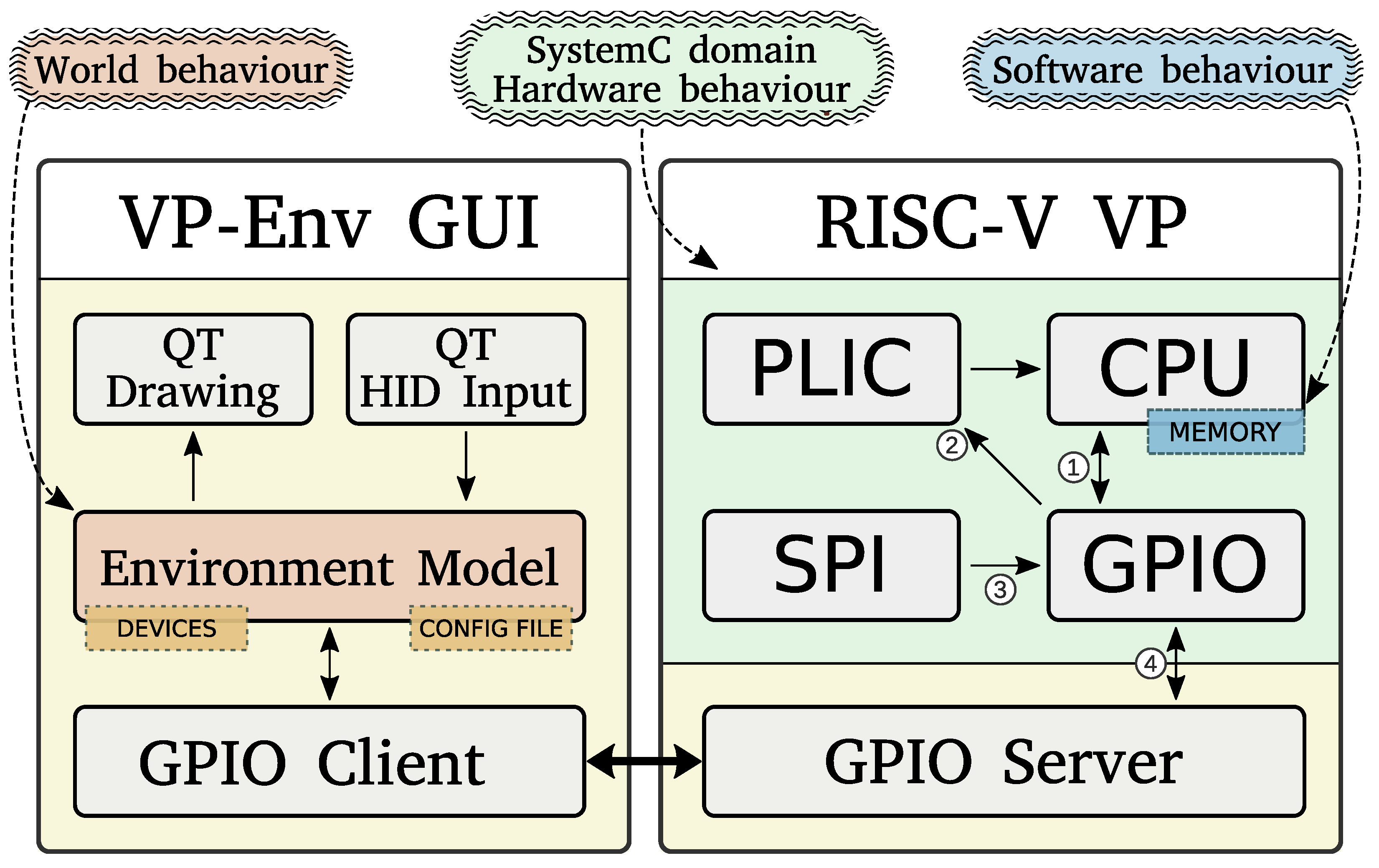
Figure 1 shows an overview on our approach. It consists of two standalone executables: the modified RISC-V VP and our new VP Environment GUI. The RISC-V VP is organized in the SystemC domain (the hardware model residing in simulation time, highlighted in green) and the GPIO server (bottom right). The SystemC peripherals relevant to this work and their interactions will be described in more detail in Section 4.2. The GPIO server interfaces between the SystemC GPIO peripheral to the environment model in physical (i.e., wall clock) time, highlighted in yellow.
The VP environment GUI (VP-Env GUI, on the left side) consists of the GPIO client (bottom left), the environment model and the QT modules for the GUI. The GPIO client is responsible for obtaining and setting the pin states to the simulated hardware (the RISC-V VP), while the environment model (highlighted in orange) models the world behavior based on the configured devices and user input (see Section 4.3). The protocol between the GPIO client and the GPIO server is described in more detail in Section 4.2.2. The environment model manages the devices such as buttons, LEDs, etc., and their respective connections to individual pins, and is shown in Section 4.3. The QT interface modules handle the drawing functions and distribute keyboard/mouse input events to the respective environment components, and is not shown in this work for brevity.
4.2. VP Peripheral Interfaces
As the GPIO peripheral resides in the user-space scheduled SystemC threading scheme, an interface to the asynchronous “real time” world is needed. This interface is modeled in the form of the GPIO server, which accepts TCP connections from a GPIO client to receive and send pin status updates. To minimize the dependency of the VP to our environment simulation, the server does not act (and thus impose an execution overhead) when no client is connected. Furthermore, the GPIO client in the environment simulation performs active polling on the server, where it sends changed pins on the environment side and requests the current status on the VP side. This way, the execution overhead on a running VP with an environment simulation is minimized at the cost of missed changes that happen between the update cycles. With LEDs and buttons that interact with humans, this is usually enough, but this loss of information would disable fast digital transmissions such as SPI communication. This is why, when the GPIO peripheral is configured to do so, the GPIO server and client will transmit their respective payload. For digital communication interfaces such as SPI, our approach abstracts the underlying protocol and directly transmits the payload to enable lossless communication and a faster simulation time.
4.2.1. SystemC Peripheral Interface
The GPIO peripheral is accessed through the device’s bus (Figure 1, ➀), where it can be configured and read by the software running on the CPU. It has an asynchronous (with respect to the CPU clock) interrupt line ➁ to notify the PLIC (and thus the CPU later) when a configured input triggers, and, lastly, a direct interface from the SPI peripheral ➂, where the payload bytes are sent directly into the GPIO interface.
“Outside” pin changes (from the VP environment GUI) are handled by using SystemC AsyncEvents to notify the synchronous (with respect to the SystemC simulation time) GPIO thread of pin changes ➃, which, in turn, notifies the PLIC if an interrupt is configured for the corresponding change type.
4.2.2. GPIO-Protocol
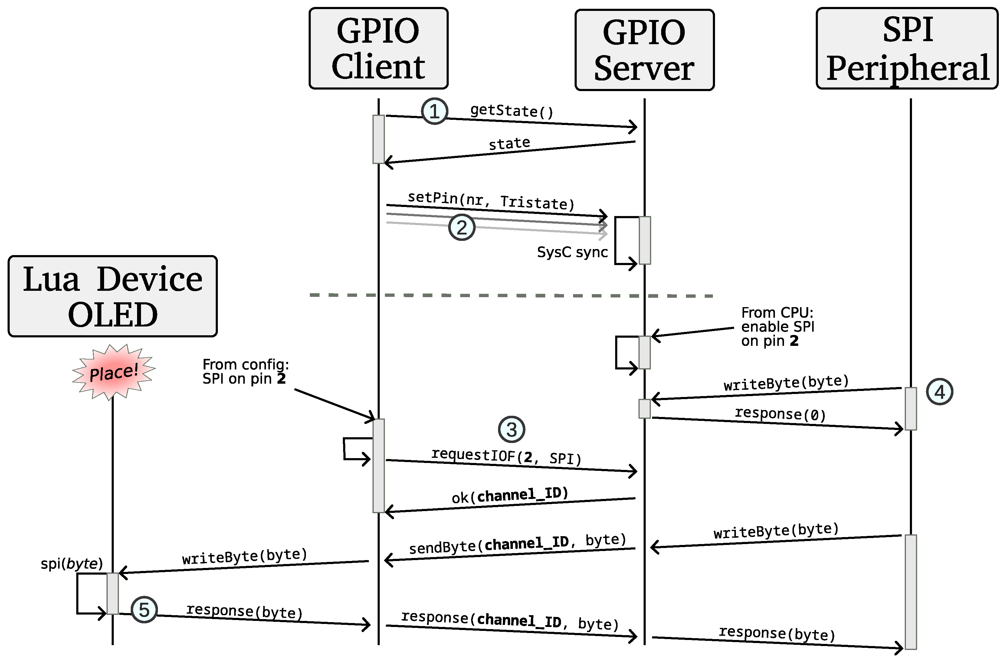
Upon startup, the GPIO server opens a TCP socket and listens to incoming connections from the GPIO client. The GPIO client in the virtual environment GUI then connects to the server and begins polling with a getState command to request all pin states (see Figure 2, ![Jlpea 12 00052 i001]() ). The response is a list of states for all pins that may assert either direct values (LOW, LOW_WEAK, HIGH, HIGH_WEAK and FLOATING), or any of the current supported IO-functions: SPI, SPI_NORESPONSE, BITSYNC and PWM, and reserved future functions such as UART and I2C. If an environment device (such as a button) sets a pin, it is always sent immediately over the channel (Figure 2,
). The response is a list of states for all pins that may assert either direct values (LOW, LOW_WEAK, HIGH, HIGH_WEAK and FLOATING), or any of the current supported IO-functions: SPI, SPI_NORESPONSE, BITSYNC and PWM, and reserved future functions such as UART and I2C. If an environment device (such as a button) sets a pin, it is always sent immediately over the channel (Figure 2, ![Jlpea 12 00052 i002]() ). Note that this happens throughout the execution of the environment in regular intervals, indicated by the dashed line after
). Note that this happens throughout the execution of the environment in regular intervals, indicated by the dashed line after ![Jlpea 12 00052 i002]() .
.
 ). The response is a list of states for all pins that may assert either direct values (LOW, LOW_WEAK, HIGH, HIGH_WEAK and FLOATING), or any of the current supported IO-functions: SPI, SPI_NORESPONSE, BITSYNC and PWM, and reserved future functions such as UART and I2C. If an environment device (such as a button) sets a pin, it is always sent immediately over the channel (Figure 2,
  ). Note that this happens throughout the execution of the environment in regular intervals, indicated by the dashed line after .
The GPIO client may also request an IO-function channel, in which case, the GPIO server will generate a unique channel ID (Figure 2, ![Jlpea 12 00052 i003]() ) and open (if not already existing) a second TCP socket to which the GPIO client will connect (not shown in Figure 2 for brevity). If some on-chip peripheral writes to one of the GPIO IO-function inputs, but the corresponding pin is not yet “tracked” by the GPIO client, the GPIO peripheral will discard the message. Additionally, in case of a two-way protocol, it will respond as if no device was connected (e.g., a zero, Figure 2,
) and open (if not already existing) a second TCP socket to which the GPIO client will connect (not shown in Figure 2 for brevity). If some on-chip peripheral writes to one of the GPIO IO-function inputs, but the corresponding pin is not yet “tracked” by the GPIO client, the GPIO peripheral will discard the message. Additionally, in case of a two-way protocol, it will respond as if no device was connected (e.g., a zero, Figure 2, ![Jlpea 12 00052 i004]() ). If the pin has an already registered “channel”, the datum is transmitted to the GPIO client, with the actual response forwarded if needed (Figure 2,
). If the pin has an already registered “channel”, the datum is transmitted to the GPIO client, with the actual response forwarded if needed (Figure 2, ![Jlpea 12 00052 i005]() ).
).
 ) and open (if not already existing) a second TCP socket to which the GPIO client will connect (not shown in Figure 2 for brevity). If some on-chip peripheral writes to one of the GPIO IO-function inputs, but the corresponding pin is not yet “tracked” by the GPIO client, the GPIO peripheral will discard the message. Additionally, in case of a two-way protocol, it will respond as if no device was connected (e.g., a zero, Figure 2,
  ). If the pin has an already registered “channel”, the datum is transmitted to the GPIO client, with the actual response forwarded if needed (Figure 2,
  ).
).Note that, in the case of SPI, there is also the SPI_NORESPONSE mode (unidirectional), which can be requested by the GPIO client, where the response phase is omitted by the GPIO client and the server will continue to respond directly with a zero. This is especially useful for devices that do not implement a response anyway, to further reduce the overall latency.
4.3. VP Environment Model
In order to support the design process to build an environment model with the accompanying GUI, we provide a set of building block components that can be re-used across different environments and designed our GUI to support configuration and placement via a configuration file. In the following, we describe both aspects in more detail.
C++ Building Blocks
At the moment, we have, in total, designed five ready to use C++ components as building blocks to support the design engineer in building environment models:
- Button: simple input area on screen that changes its state by mouse click or button press and sets/resets a pin value.
- LED: a colored light spot that changes its brightness from transparent to a configured color tone depending on a pin input value. This value can either be binary (on/off) or a PWM ratio sent as a float.
- RGB LED: an extension to the regular LED, directly mixing the three colors for convenience.
- Seven-segment display: arranged color lines with background of a configurable size, connected to up to seven input pins.
- Display: an SPI OLED display with an internal state machine, connected to one of the digital SPI inputs and two pins for slave select and data/command switch.
Besides this set of C++-implemented components, our environment model architecture is designed to be extensible and, as such, we can add additional components to increase our toolbox. For rapid prototyping purposes, we also implemented a Lua-scripting interface for modeling devices, as explained in the following Section 5.
5. Rapid Prototyping Using Lua Scripting
To increase the usability of our VP environment modeling tool, we added a device scripting engine. This allows developers to focus on the actual behavior of devices without having to understand the whole system, to not have to re-build the framework for each change in a device and to increase modularity for an easier community-driven library of devices.
Such a scripting engine has to be fast, memory efficient and easily learnable. Without a particular scientific relevance, we chose Lua as the driving scripting language, as it is widely used in games and other applications where execution speed and a low memory footprint is key. Though the Python language was considered, as it is widely used nowadays in more high-level applications, its interpreters for C/C++ programs compare rather laboriously and (slightly) slowly.
For the interface between Lua and C/C++, we kept the dynamically typed language style, and activated offered interfaces in a “duck typing” way. This means that, if a script is loaded, it is checked whether it implements certain functions that are expected by our framework. These can then be used by the configuration mechanism to enable/connect the following currently implemented functions: SPI, Pin input/output, Configuration change, Button/Mouse input, and Graphics.
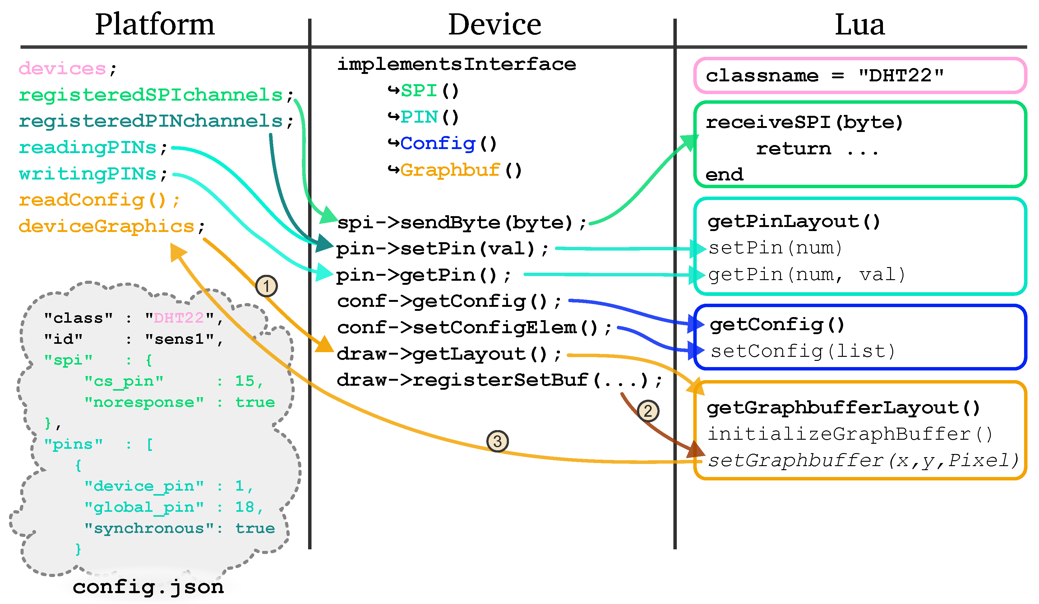
In Figure 3, a brief overview of the interface registry is shown. On the right side, the Lua tab, the functions to be implemented are grouped by their interfaces (colored). Higlighted in bold are the necessary functions for each interface (the Graphics interface is special, which will be discussed in the following paragraphs) to be recognized by the Device wrapper (central tab). Upon instantiation, the device wrapper will check for the existence of these functions and add the corresponding interfaces to the C++-world. The Platform then instantiates and stores all devices listed in the configuration file (bottom left). For each of the interfaces, a central registry is held for all devices to speed up the lookup of each frame.
A Lua scripted device may implement a set of functions and have at least a member classname, which is used to identify and instantiate this device (see Figure 3). For pin input/output, it has to implement at least the function getPinLayout(), where it defines the number of input or output pins during the instantiation setup phase (see also Figure 6). The host system will then periodically call getPin(num) (if implemented) to request updates, and setPin(num, val) if registered and connected pins are updated from outside the device. A pin is updated asynchronously (i.e., only when the environment model updates; see Section 4.2.2) per default, unless the environment configuration sets it as synchronous. This is to save bandwidth and performance. Normal, asynchronously sensitive pins are registered in the reading- and writingPINs data structures, whereas synchronous pins are handled in the registeredPINchannels data structure, as it is considered as an IO-function internally. SPI connections are handled by implementing receiveSPI(byte) and is called synchronously when the device is connected to an SPI port and receives something. Note that the function may return a value that is passed back to the processor if not configured in SPI_NORESPONSE mode. If the device implements the setConfig(list) functions, it may receive configuration updates in the form of a key-value list during setup from the json config file. Additionally, it may implement getConfig(), from where the (default) settings may be viewed and reconfigured in the GUI. For GUI interactions (Button/Mouse input), the device may implement onKeypress(keycode, press_release) or onClick(press_release). Note that, for onClick, a graphical representation is needed.
The interface for graphics is slightly more interesting, as the environment GUI offers functions to the device once it defines the getGraphbufferLayout() function. During setup(Figure 3, ![Jlpea 12 00052 i006]() ), the GUI calls this function and reserves a memory region with the requested image size and format (currently only RGBA8888), and inserts the callback function (Figure 3,
), the GUI calls this function and reserves a memory region with the requested image size and format (currently only RGBA8888), and inserts the callback function (Figure 3, ![Jlpea 12 00052 i007]() ) get- and setGraphbuffer(x,y,Pixel), which directly access the internal image buffer. A Pixel is a custom data type that combines red, green, blue and alpha values. These functions may be called by the device during all callbacks (Figure 3,
) get- and setGraphbuffer(x,y,Pixel), which directly access the internal image buffer. A Pixel is a custom data type that combines red, green, blue and alpha values. These functions may be called by the device during all callbacks (Figure 3, ![Jlpea 12 00052 i008]() ).
).
 ), the GUI calls this function and reserves a memory region with the requested image size and format (currently only RGBA8888), and inserts the callback function (Figure 3,
  ) get- and setGraphbuffer(x,y,Pixel), which directly access the internal image buffer. A Pixel is a custom data type that combines red, green, blue and alpha values. These functions may be called by the device during all callbacks (Figure 3,
  ).
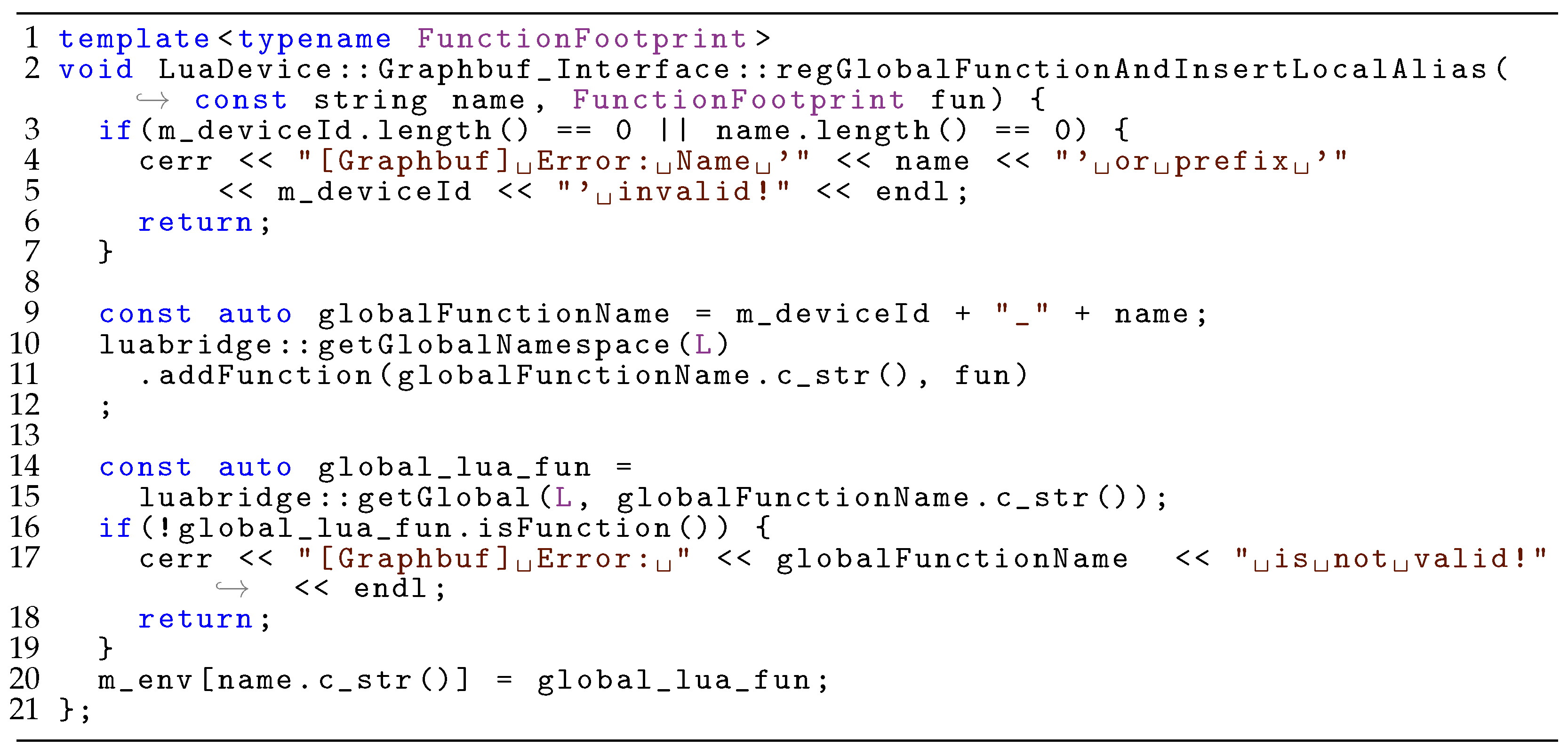
).Due to technical reasons, all scripted devices run in one single Lua interpreter state as scoped chunks for the best memory and execution speed. This means that a script is loaded into a table, where it may only access pre-defined global functions without access to the other script’s functions. All devices may call setGraphbuffer(..), but they may only access their own buffer. To enable this, we opted for prefixed global C functions (e.g., button1_setGraphbuffer(..), Figure 4, Line 9). This is a technical limitation of the used LuaBridge3, where C functions may only be global These are inaccessible for the scoped device scripts (chunks) until they are inserted into the respective Lua meta-table (Figure 4, Line 20), and without the prefix.
5.1. Configuration
Our VP environment loads a json-formatted configuration file on start-up for ease of customizing the user interface. An example is shown in Figure 5. In the window section, a background image (Line 3) and a desired window size (Line 4) can be defined (which defaults to the background image size).
After that, all implemented/loaded device classes may be referenced and instantiated in the devices section (Line 6). A device entry must have a class and an id (Lines 9 and 10). The class references the building blocks classname (see Section 5), while the id must be a name that is unique to the instance. Further items depend on the implemented interface of the specific building block (see Figure 3). For example, a Lua-implemented button button_lua offers the graphics (Line 11), onKeypress (Line 16) and pin (Line 17) interface. The OLED device (Line 44) was implemented in both Lua and C++, with the latter being instantiated in this example.
5.2. Scoping Layers
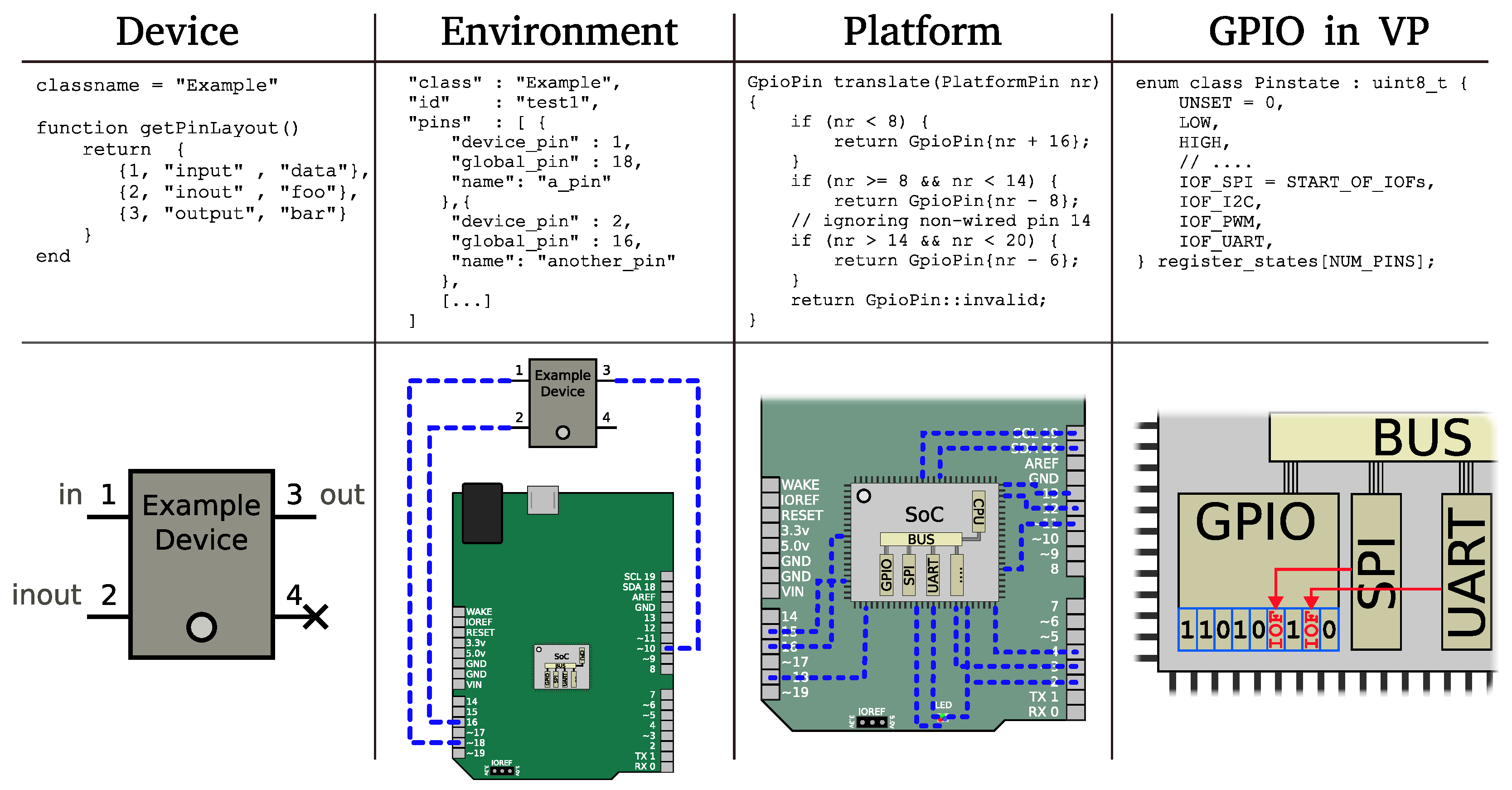
To increase the modularity in the whole HW stack from the device to SoC peripheral, the environment model consists of four layers: the device layer, the environment layer, the platform layer and the GPIO layer in the GPIO peripheral of the VP (see Figure 6).
The device layer is scoped to every individual device, which define the pin and other protocol descriptions according to the respective interfaces (see Section 5). In the environment layer, all instantiated devices are connected to the global pin numbers. This would normally be carried out via a prototyping breadboard or a PCB. It is allowed to not connect pins. The pins between the labeled “global” connectors of a platform (such as the HiFive 1) into the chip’s GPIO register offsets are translated in the platform layer. Lastly, in the GPIO module that resides in the VP, the actual pin states are set/read according to Section 4.2.2 and can either contain per-pin managed digital levels (see Section 4.2.1) or pass through to an IO-function such as SPI.
5.3. Example Devices
To explain the concept better, we will show two of the currently implemented devices in more detail: a simple red LED (see Figure 7) and a more complex OLED display (Figure 8).
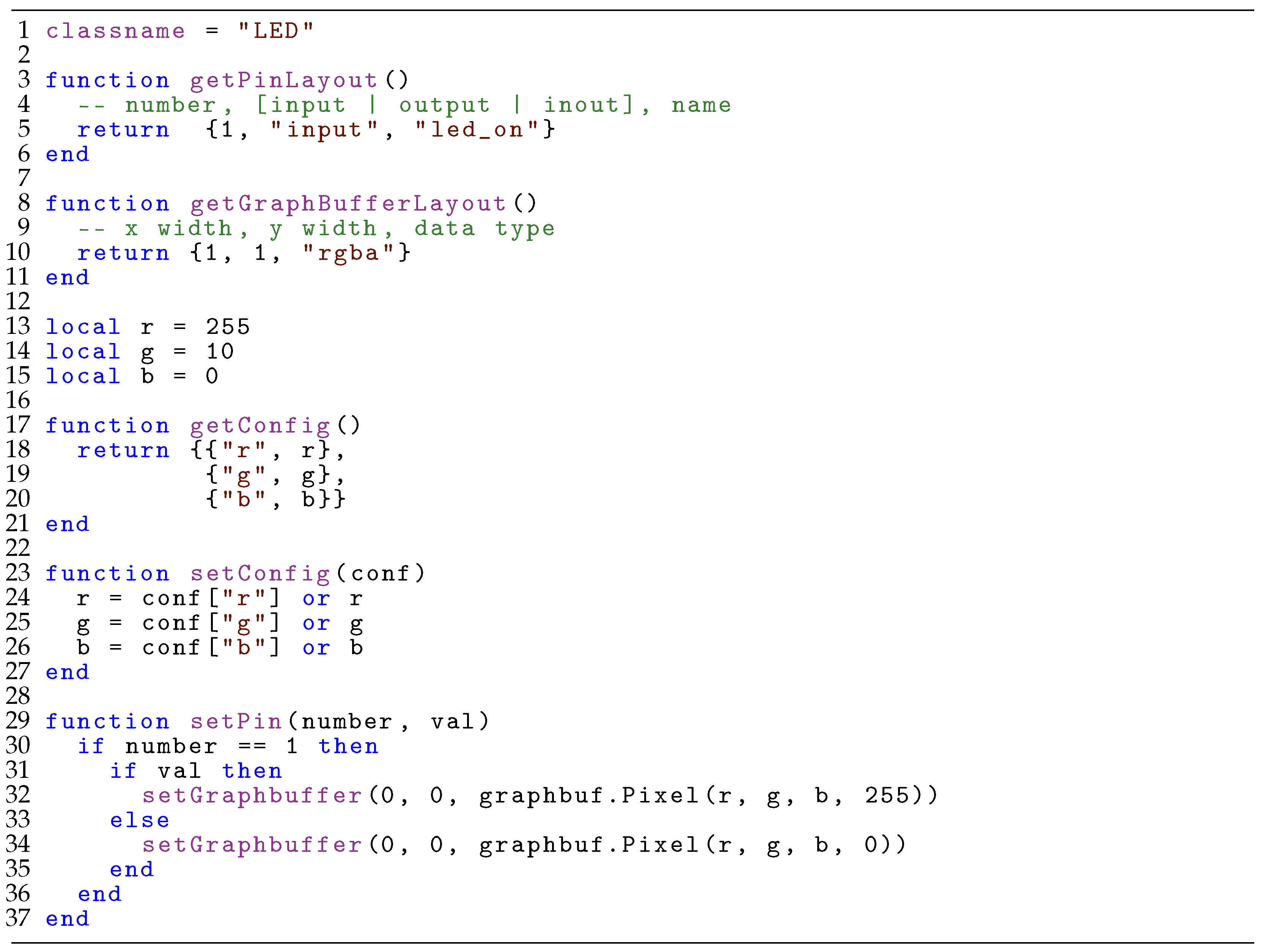
5.3.1. LED
The LED implementation in Figure 7 uses the pin, config and graphic interfaces. In Lines 3–6, the module defines only one pin, with the number 1 as an input pin and the description string of “led_on”. Lines 8–11 request only one color pixel from the graphics system, which is accessed later via setGraphbuffer(0,0, ⋯) on Lines 32 and 34. Lines 13–15 define local variables for the displayed color, which are set or read by the configuration file or during the runtime via getConfig() and setConfig(conf) in Lines 17 and 23, respectively. The actual display action happens if the input pin (1) is changed (Lines 29–37). The call supports multiple pins, so setPin(⋯) includes the pin number and the (boolean) value if it is HIGH or LOW.
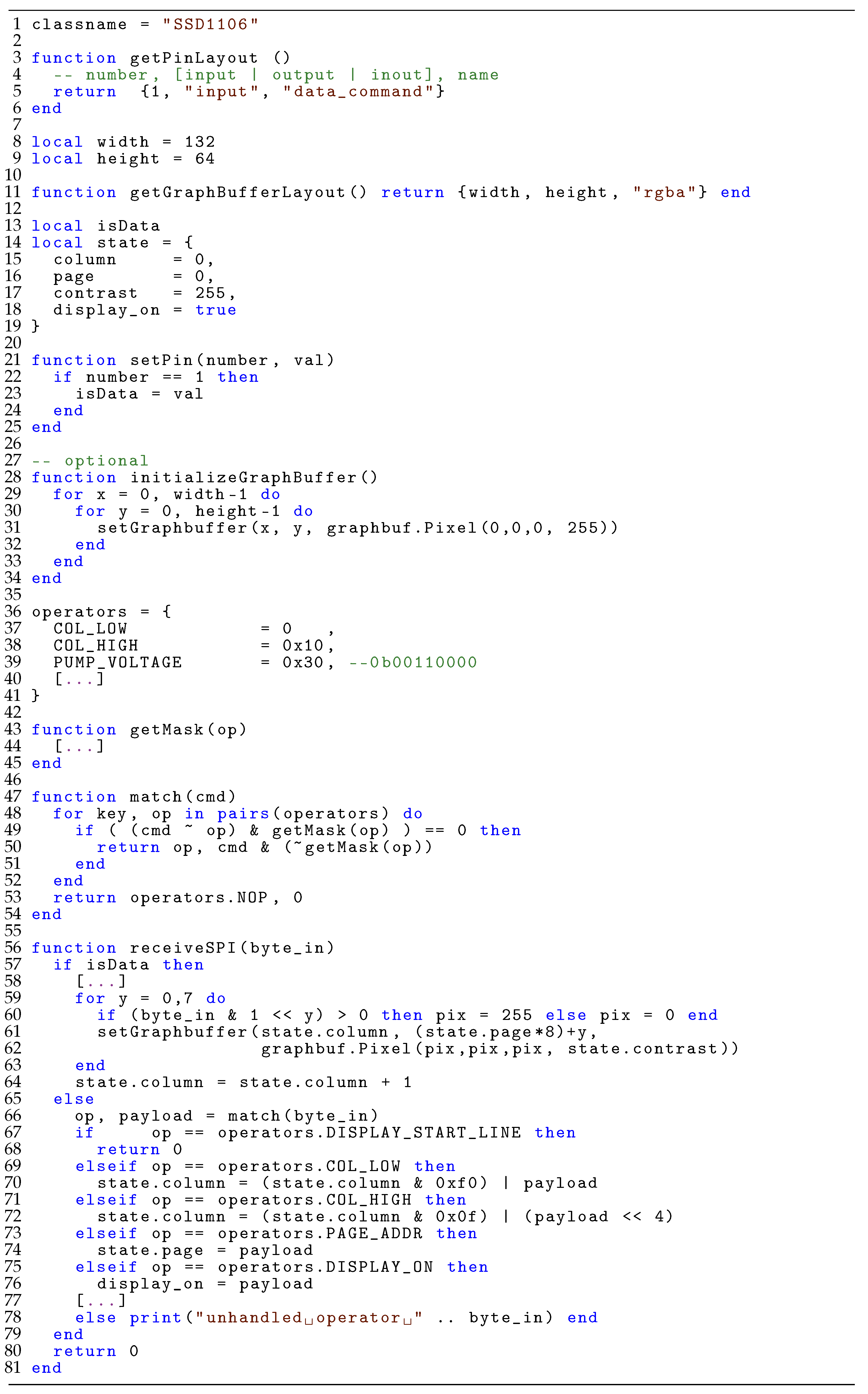
5.3.2. SSD1103 OLED Display
In Figure 8, a more sophisticated example is given. It implements the already known pin interface, but also the SPI interface with the function receiveSPI(byte_in) (Lines 56–81). Note that, for brevity, some of the internal logic is omitted (Lines 44, 58, 77). In Lines 36–41, the most common operator bytes are defined. The omitted function getMask(op) determines the value bits of an input command byte, which is then used by the match(cmd) function (Lines 47–54) to decode incoming raw bytes. Lastly, in receiveSPI(byte_in) (Lines 56–81), the actual drawings to the frame buffer are performed when the incoming SPI byte is detected as data (if the data_command pin was set HIGH). In Lines 57–65, the translation from 1-bit-pixel rows to the pixelwise frame buffer is carried out, including the increment of the current column pointer. Some of the command handling is shown in Lines 65–79, where internal state variables are changed.
6. Evaluation
In this section, we will show some use-cases for our VP environment by modeling two example environments along with their interacting software (Section 6.1), give a performance evaluation of different modeling strategies (and comparing to the baseline RISC-V VP, Section 6.2) and, lastly, give a short demonstration on how we used it in our own lectures (Section 6.3).
6.1. Modeling Case-Studies
We implemented our proposed approach for VP-driven environment modeling and interaction in the RISC-V context using the open source RISC-V VP as foundation, which is available at GitHub [4]. To demonstrate the effectiveness of our approach in building feature rich environments, we designed two example environments in combination with different firmware applications as a case-study. In the following, we present both case-studies in more detail (Section 6.1.1 and Section 6.1.2).
6.1.1. Breadboard Environment
To demonstrate the usability of our approach as a rapid prototyping methodology, we designed a breadboard environment and configured a button, an LED and a seven-segment display, as well as the built-in RGB-LED of the HiFive1 board. An excerpt of the corresponding configuration file can be found in Figure 5. The corresponding graphical display of the environment is shown in Figure 9. Besides the already mentioned components, the environment also displays the connection between the respective GPIO pins of the HiFive1 and the breadboard. During the VP-driven simulation, the environment GUI was updated accordingly to reflect the current execution state of the VP.
The firmware is held as simple in this example: it counts a number in seconds using the core local interrupter (CLINT) timer, and renders it to the seven-segment display. Whenever the button is pressed, the count direction is reversed accordingly. The single LED is changed every second. Due to the built-in RGB LED segments always being connected to certain GPIO pins of the seven segment display, its color changes and mixes as well.
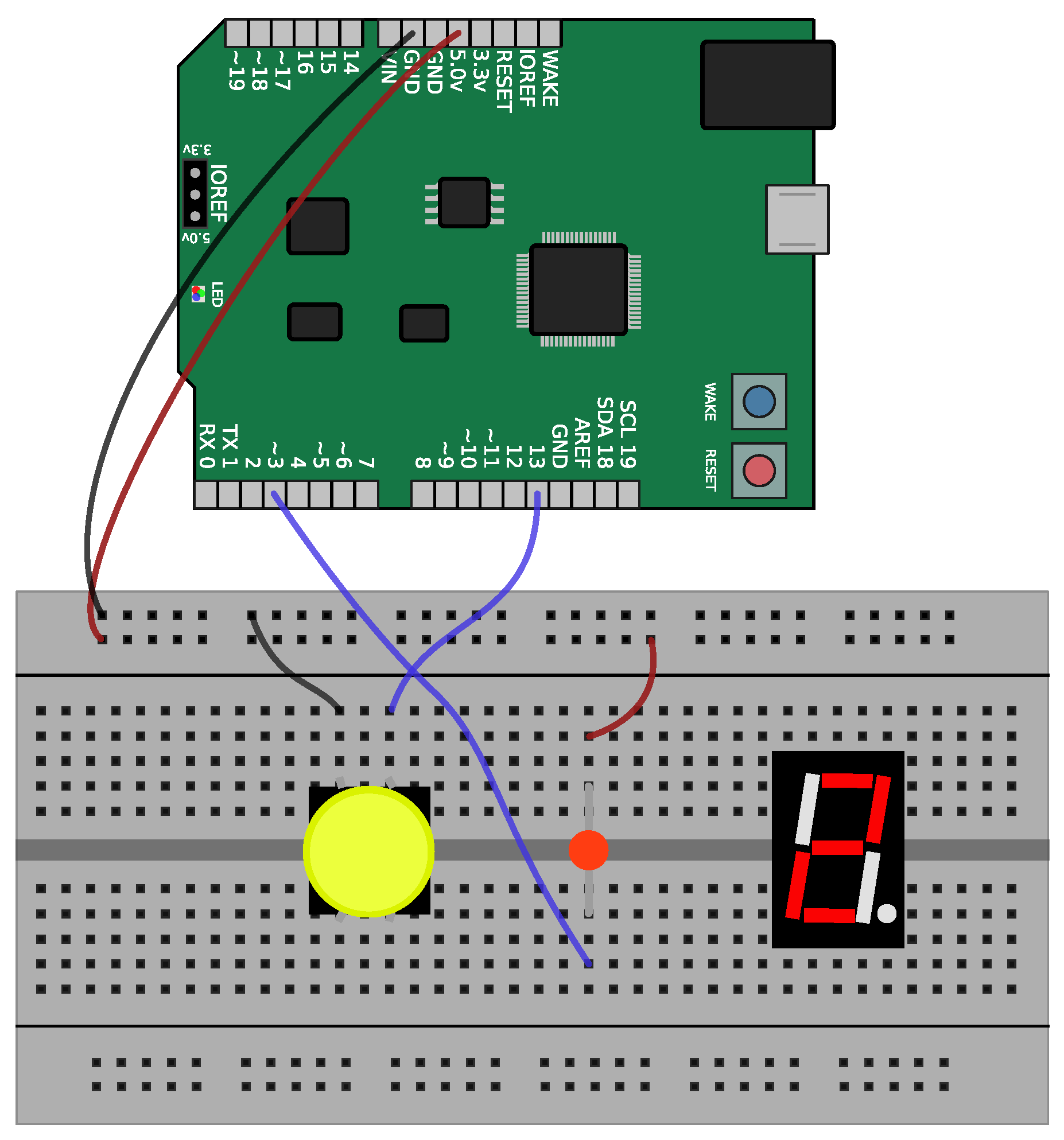
6.1.2. OLED Display Shield with Buttons
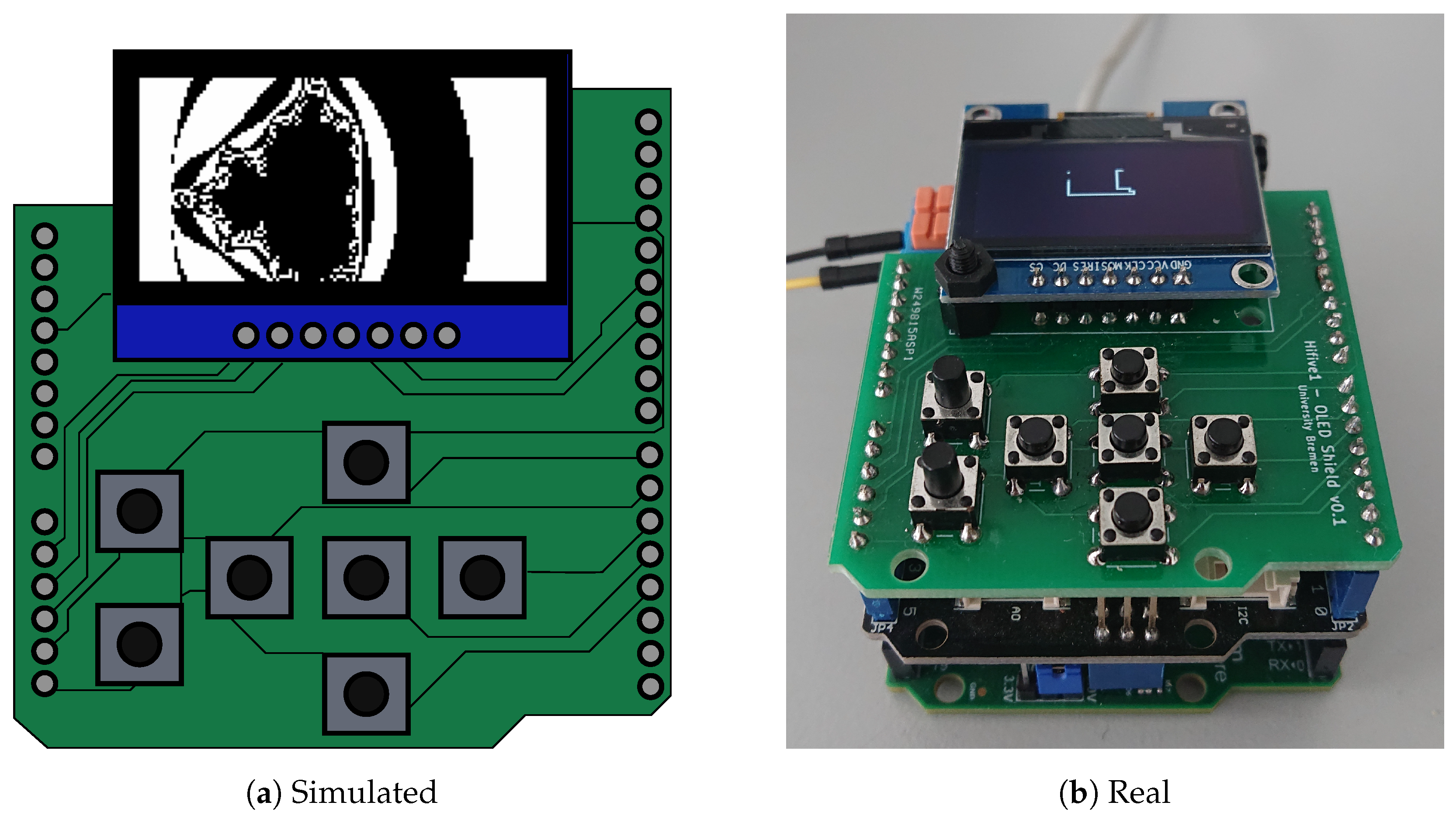
For a more sophisticated example, we modeled a hand-held “gaming” device with seven input buttons and a 64-by-128-pixel-wide OLED screen. An overview of this system is shown in Figure 10, with the left side showing the virtual environment and the right side the corresponding real physical device. The screen is connected via SPI and demonstrates the bytewise I/O functions of our GPIO and environment model. The buttons are connected to the ground and require a pull-up resistor on the input pins to work, while the OLED screen is interfaced via an SSD1306 (https://cdn-shop.adafruit.com/datasheets/SSD1306.pdf, last accessed 4 September 2022) compatible protocol, consisting of the usual SPI pins Master In Slave Out (MISO), Clock (CLK) and a Data Command (DC) input. This interface also demonstrates the requirement of synchronicity between the abstracted byte-wise SPI transmissions and the GPIO-handled (software driven) Data/Command (DC) pin, where a small transmission jitter of data vs. the DC pin would already result in a glitchy or inoperable display. An excerpt of the Lua implementation can be found in Figure 8.
To test the interaction between the user input and output, we programmed a demo snake game that listens to the up, down, left and right buttons in an interrupt routine and draws a gaming field on the screen. With the key mapping of our environment model, it can be played by clicking on the on-screen buttons or via the arrow-keys on the keyboard. As the RISC-V VP is binary-compatible to the HiFive1 board, the same program can be used and played on the real board, after the PCB has been manufactured (see Figure 10a). For demonstration purposes, we built another firmware, besides the snake game, that displays a Mandelbrot visualization on the same device (as shown on Figure 10b).
6.2. Performance Evaluation
For performance evaluation purposes, we designed a non-interactive test program that first calculates 40 frames in a Mandelbrot set visualization (see Figure 10a) that uses software floating-point arithmetic to render the fractal. It then fades the display using the background illumination command and draws 1000 characters of pre-defined, randomized text to the screen. After this, the program exits with a special RISC-V exit sequence that is handled in the RISC-V VP. This is, of course, not handled by the real processor. While the Mandelbrot set visualization is computationally intensive, as every pixel is calculated individually, the text stream is only limited by the SPI-bandwidth as it uses lookup-buffers for the font and addresses the native eight-pixel-rows per byte.
In addition, we modeled the SPI OLED display three times: 1. in the SystemC VP, communicating directly with the SPI device over TLM, sharing only the screen buffer over memory-mapped I/O to the GUI; 2. in the VP environment GUI as a C++ device, using our GPIO protocol; and 3. in the VP environment GUI as a Lua device, using our GPIO protocol (see Figure 8).
The results of this experiment can be found in Table 1. The first column describes the Test type: Baseline (unmodified RISC-V VP with non-functional mock-up GPIO peripheral); Disconnected (our modified RISC-V VP with the display modeled in SystemC, but no connection to the environment); and GUI-connected (our modified RISC-V VP with the connected environment GUI actively displaying the execution state). The connected tests were built in four different set-ups: SystemC-Device, where the OLED display driver is directly connected to the SPI peripheral in SystemC sharing the screen buffer with our GUI; Bidirectional C++-Device, where the driver is modeled in our environment GUI and the SPI peripheral awaits the answer byte via the protocol; Unidirectional C++-Device, where the device’s answer is discarded for speedup; and, finally, Unidirectional Lua-Device, where the logic of the display driver is modeled in our Lua scripting engine.
The next column, Time, reports the real time as reported by the program time of the whole simulation with an already started GUI (if applicable). # Exec. Instr. refers to the number of native machine instructions (not pseudo-instructions) executed until the test end. Note that the number differs slightly for the same binary due to different behavior when the GPIO memory mapped region is either mock-up memory (Baseline), correct but disconnected (Disconnected) or responding to actual SPI devices (GUI connected). Lastly, we calculated the number of Million Instructions Per Second (MIPS) to offer a comparison to other simulation approaches. All tests were conducted on a desktop grade AMD Ryzen 3700G processor with 32 GiB RAM, and outperformed the real HiFive1 setup; especially in memory-intensive tests, which is usually not possible with RTL models (note that the RISC-V VP has the feature to lock the CLINT (internal timer) to either simulation- or wall clock time).
As can be observed, a connected and running VP environment has a minimal impact on the execution speed of the VP. Besides the asynchronous communication scheme, the minimal overhead could be achieved through the use of a multi-core processor, as the RISC-V VP uses the single-threaded SystemC reference implementation. Thus, the RISC-V VP and the environment GUI can be executed in parallel with little to no interference. Secondly, it can be noted that the implementation of a high-throughput device (such as the OLED display) in the Lua scripting language does not add a significant run-time overhead to the simulation speed, as long as the response is discarded. Note, however, that the refresh rate of the environment GUI drops slightly, as Lua devices accesses to the frame buffer are generally slower because of the C-wrapper (see Figure 3). The refresh rate in all tests varied between 10 and 20 Hz, limited to 20 Hz.
The overall impact of our approach on execution speed can be observed against a baseline version of the GPIO peripheral, where any accesses to the memory mapped IO-interface are ignored (pass-through to memory). This reveals only a runtime overhead on average for the benefit of a functioning, interactive GPIO interface.
6.3. Educational Tool for Teaching
Among others, we offer a system-level design lecture that also covers programming embedded systems. During the COVID-19 pandemic, there was no possibility for the students to interact with physical prototype boards such as the Sifive Hifive1. As the students covered implementing their own small VPs, it was easy to show them the principles of the more complex RISC-V VP. The students could then use and program our digital version of the Hifive1 board to understand the basic concepts of interrupt handling and how embedded systems interact with their environment. As the RISC-V VP can be analyzed using normal software-based debuggers such as GDB, we can show the detailed steps of different control flows during the runtime, and how software and hardware modules interact between each others. The small exercises were laid out in incremental steps to program an interrupt-triggered blinking LED while reacting to button presses. One year, the final lectures could be held in person, where the students could test their own programs on real Hifive1 boards supplied by the university.
Overall, we noted that the RISC-V VP with the environment model extension, while posing an initial learning curve, was very helpful during remote teaching and was still nice to have in in-person teaching as every student could test and build their programs at home without having to supply real hardware. We suppose that it will also be beneficial for more practical-focused embedded programming courses; especially when using hardware that is either too costly/complex to be supplied to every student or hardware that requires special programming devices.
7. Discussion and Future Work
Our evaluation demonstrates the applicability of our approach in building advanced VP-driven environment models for embedded systems efficiently to enable a full-platform simulation early in the design flow. To further boost our approach, for future work, we plan to:
- Extend the GUI to build the environment configuration live in an interactive way instead of using a static configuration file. Moreover, we want to investigate enabling dynamic modifications of the environment configuration at the runtime in order to facilitate the rapid prototyping process or for debugging purposes (development has already started).
- Investigate a VP-driven hardware-in-the-loop integration that allows for attaching real physical HW objects with the VP-based simulation. This would allow for mixing virtual and physical environment objects. In addition, it allows a step-wise approach to refine models and specifically debug certain physical objects by providing virtual wrappers for the others.
- Look into techniques to boost the simulation performance of the VP-driven simulation. In particular, the integration of just-in-time compilation techniques seems very promising but requires special attention to be integrated with a SystemC-based simulation in combination with the environment model communication.
- Investigate the integration of extra-functional models with the VP-driven simulation to enable a fast and accurate estimation of extra-functional properties in a full platform setting. This requires appropriate interfaces and dedicated techniques for measurement and synchronization between the VP and environment models.
8. Conclusions
We presented an effective methodology for advanced environment modeling and interaction for VPs in the RISC-V context to enable the design of an advanced embedded system early in the design flow. We provided a library with a set of building blocks and support for several hardware communication interfaces. For visualization purposes of the environment, we designed an interactive GUI that communicates to the VP through TCP connections. To ease the environment setup, the model was specified through a configuration file. For rapid prototyping purposes, we added a modeling layer that leverages the dynamic Lua scripting language to design components and integrate them with the VP-based simulation. Our evaluation with two different case-studies demonstrated the applicability of our approach in building virtual environments effectively and correctly. To advance the RISC-V community and stimulate further research, we provided our complete framework, including all case-studies as open source on GitHub. We also believe that the combined VP platform can be very beneficial for education purposes in lectures.
Author Contributions
P.P.: software; writing—original draft (lead). V.H.: supervision; writing—review and editing (equal). R.D.: supervision; funding acquisition; project administration. Special thanks goes to Karl Aaron Rudkowski, who supported the software development. All authors have read and agreed to the published version of the manuscript.
Funding
This work was supported in part by the German Federal Ministry of Education and Research (BMBF) within the projects ECXL under contract No. 01IW22002 and Scale4Edge under contract No. 16ME0127.
Data Availability Statement
Conflicts of Interest
The authors declare no conflict of interest.
Abbreviations
| ADC | Analog–Digital Converter |
| RISC | Reduced Instruction Set Computer |
| ISA | Instruction Set Architecture |
| IoT | Internet of Things |
| SoC | System on Chip |
| CPU | Central Processing Unit |
| CLINT | Core Local Interruptor |
| TLM | Transaction-Level Modeling |
| HW | Hardware |
| SW | Software |
| VP | Virtual Prototype |
| PCB | Printed Circuit Board |
| SPI | Serial Peripheral Interface |
| GPIO | General Purpose Input/Output |
| LED | Light-Emitting Diode |
| OLED | Organic LED |
| UART | Universal Asynchronous Receiver–Transmitter |
| PWM | Pulse Width Modulation |
| DAC | Digital–Analog Converter |
| GUI | Graphical User Interface |
References
- Waterman, A.; Asanović, K. (Eds.) The RISC-V Instruction Set Manual; Volume I: Unprivileged ISA; University of California: Berkeley, CA, USA, 2019. [Google Scholar]
- Waterman, A.; Asanović, K. (Eds.) The RISC-V Instruction Set Manual; Volume II: Privileged Architecture; University of California: Berkeley, CA, USA, 2021. [Google Scholar]
- De Schutter, T. Better Software. Faster!: Best Practices in Virtual Prototyping; Synopsys Press: Mountain View, CA, USA, 2014. [Google Scholar]
- RISC-V Virtual Prototype. Available online: https://github.com/agra-uni-bremen/riscv-vp (accessed on 22 September 2022).
- Herdt, V.; Große, D.; Pieper, P.; Drechsler, R. RISC-V based virtual prototype: An extensible and configurable platform for the system-level. JSA 2020, 109, 101756. [Google Scholar] [CrossRef]
- SiFive FE310-G000 Manual. Available online: https://sifive.cdn.prismic.io/sifive%2F500a69f8-af3a-4fd9-927f-10ca77077532_fe310-g000.pdf (accessed on 17 September 2020).
- Pieper, P.; Herdt, V.; Große, D.; Drechsler, R. Dynamic Information Flow Tracking for Embedded Binaries using SystemC-based Virtual Prototypes. In Proceedings of the 2020 57th ACM/IEEE Design Automation Conference (DAC), San Francisco, CA, USA, 20–24 July 2020; pp. 1–6. [Google Scholar] [CrossRef]
- Tempel, S.; Herdt, V.; Drechsler, R. SymEx-VP: An open source virtual prototype for OS-agnostic concolic testing of IoT firmware. J. Syst. Archit. 2022, 126, 102456. [Google Scholar] [CrossRef]
- Koenig, M.; Rasch, R. Digital Teaching an Embedded Systems Course by Using Simulators. In Proceedings of the 2021 ACM/IEEE Workshop on Computer Architecture Education (WCAE), Raleigh, NC, USA, 17 June 2021; pp. 1–7. [Google Scholar] [CrossRef]
- Pieper, P.; Herdt, V.; Drechsler, R. Advanced Environment Modeling and Interaction in an Open Source RISC-V Virtual Prototype. In Proceedings of the Great Lakes Symposium on VLSI 2022 (GLSVLSI ’22), Irvine, CA, USA, 6–8 June 2022; ACM: New York, NY, USA, 2022; pp. 193–197. [Google Scholar] [CrossRef]
- Spike RISC-V ISA Simulator. Available online: https://github.com/riscv/riscv-isa-sim (accessed on 6 December 2021).
- RV8. Available online: https://michaeljclark.github.io/ (accessed on 1 May 2018).
- Guo, X.; Mullins, R.D. Accelerate Cycle-Level Full-System Simulation of Multi-Core RISC-V Systems with Binary Translation. arXiv 2020, arXiv:2005.11357. [Google Scholar]
- RISCV-QEMU. Available online: https://github.com/riscv/riscv-qemu (accessed on 22 September 2022).
- Guo, X.; Mullins, R.D. Fast TLB Simulation for RISC-V Systems. arXiv 2019, arXiv:1905.06825. [Google Scholar]
- Binkert, N.; Beckmann, B.; Black, G.; Reinhardt, S.K.; Saidi, A.; Basu, A.; Hestness, J.; Hower, D.R.; Krishna, T.; Sardashti, S.; et al. The Gem5 Simulator. SIGARCH Comput. Archit. News 2011, 39, 1–7. [Google Scholar] [CrossRef]
- GEM5. Available online: https://gem5.googlesource.com/public/gem5 (accessed on 22 September 2022).
- Renode. Available online: https://renode.io/ (accessed on 22 September 2022).
- DBT-RISE. Available online: https://github.com/Minres/DBT-RISE-Core (accessed on 22 September 2022).
- ETISS (Extendable Translating Instruction Set Simulator). Available online: https://github.com/tum-ei-eda/etiss (accessed on 22 September 2022).
- Mueller-Gritschneder, D.; Dittrich, M.; Greim, M.; Devarajegowda, K.; Ecker, W.; Schlichtmann, U. The Extendable Translating Instruction Set Simulator (ETISS) Interlinked with an MDA Framework for Fast RISC Prototyping. In Proceedings of the 2017 RSP, Seoul, Korea, 19–20 October 2017; pp. 79–84. [Google Scholar]
- RISC-V-TLM. Available online: https://github.com/mariusmm/RISC-V-TLM (accessed on 22 September 2022).
- HIFIVE1-VP. Available online: https://github.com/Minres/HIFIVE1-VP (accessed on 4 April 2022).
- Pieper, P.; Wimmer, R.; Angst, G.; Drechsler, R. Minimally Invasive HW/SW Co-Debug Live Visualization on Architecture Level. In Proceedings of the 2021 on Great Lakes Symposium on VLSI (GLSVLSI ’21), Virtual Event, 22–25 June 2021; ACM: New York, NY, USA, 2021; pp. 321–326. [Google Scholar] [CrossRef]
- Synopsis Virtualizer. Available online: https://www.synopsys.com/verification/virtual-prototyping/virtualizer.html (accessed on 22 September 2022).
- SimAvr RISC-V ISA Simulator. Available online: https://github.com/buserror/simavr (accessed on 4 April 2020).
- PICsimLab-Programmable IC Simulator Laboratory. Available online: https://github.com/lcgamboa/picsimlab (accessed on 4 April 2020).
- IEEE Std 1666-2011 (Revision of IEEE Std 1666-2005); IEEE Standard for Standard SystemC Language Reference Manual. IEEE: Piscataway, NJ, USA, 2012; pp. 1–638. [CrossRef]
- OSCI. OSCI TLM-2.0 Language Reference Manual. Available online: https://www.accellera.org/images/downloads/standards/systemc/TLM_2_0_LRM.pdf (accessed on 4 April 2022).
- Sifive Hifive1 Demo Programs. Available online: https://github.com/agra-uni-bremen/sifive-hifive1 (accessed on 4 April 2022).
Figure 1.
Main architecture of our approach. Elements highlighted in green define the hardware behavior through the SystemC domain language (simplified for readability). The contents of the VP’s memory define software behavior, highlighted in blue. On the left side is the VP environment GUI, which provides the interface that is to interact with the user. The behavior of outside components is combined in the environment model with its configurable set of devices, highlighted in orange [10]. The numbers will be used in Section 4.2.1.

Figure 2.
Example sequence diagram of the GPIO-Protocol. The dashed line illustrates that the getState() and setPin(⋯) functions are continued regularly in the background. The numbers are referenced in Section 4.2.2.
Figure 2.
Example sequence diagram of the GPIO-Protocol. The dashed line illustrates that the getState() and setPin(⋯) functions are continued regularly in the background. The numbers are referenced in Section 4.2.2.

Figure 3.
Available device interfaces for Lua scripts. In the Lua tab, highlighted in bold, are the minimum necessary functions for each interface. Not shown is the Button/Mouse input interface with the functions onClick(active) and onKeypress(code, active) for better readability.
Figure 3.
Available device interfaces for Lua scripts. In the Lua tab, highlighted in bold, are the minimum necessary functions for each interface. Not shown is the Button/Mouse input interface with the functions onClick(active) and onKeypress(code, active) for better readability.

Figure 4.
Mechanism for unique global C-functions that are inserted into the Lua script’s metatable m_env as prefix-less references.
Figure 4.
Mechanism for unique global C-functions that are inserted into the Lua script’s metatable m_env as prefix-less references.

Figure 5.
Excerpt of an example configuration file for a PCB with an OLED display, used in Figure 10b.
Figure 5.
Excerpt of an example configuration file for a PCB with an OLED display, used in Figure 10b.

Figure 6.
The four layers of scoping for connections from the individual environment device to the actual register contents of the GPIO peripheral in the VP.
Figure 6.
The four layers of scoping for connections from the individual environment device to the actual register contents of the GPIO peripheral in the VP.

Figure 7.
Simple one-pixel LED model with Lua.

Figure 8.
Simple SPI OLED driver model with Lua.

Figure 9.
Image of the virtual breadboard environment with a button, a red LED and a seven-segment display on the breadboard, and the built-in RGB-LED on the HiFive1. The connections to the seven-segment display are omitted for readability reasons [10].
Figure 9.
Image of the virtual breadboard environment with a button, a red LED and a seven-segment display on the breadboard, and the built-in RGB-LED on the HiFive1. The connections to the seven-segment display are omitted for readability reasons [10].

Figure 10.
Our OLED display shield with an SSD1306 driver and seven buttons, running the demos from Section 6.2 (a) and Section 6.1.2 (b), respectively [10].
Figure 10.
Our OLED display shield with an SSD1306 driver and seven buttons, running the demos from Section 6.2 (a) and Section 6.1.2 (b), respectively [10].


Table 1.
Performance overhead test results. GPIO register accesses (read/write): 3025/946. SPI words transmitted: 58,678 (in connected tests).
Table 1.
Performance overhead test results. GPIO register accesses (read/write): 3025/946. SPI words transmitted: 58,678 (in connected tests).
| Test | Time | # Exec. Instr. | MIPS |
|---|---|---|---|
| Baseline | 27.312 s | 79,392,401 | 2.907 |
| Disconnected | 27.617 s | 79,390,408 | 2.875 |
| GUI connected | |||
| – SystemC-Device | 27.917 s | 79,390,486 | 2.844 |
| – Bidirectional C++-Device | 32.118 s | 79,390,437 | 2.472 |
| – Unidirectional C++-Device | 28.789 s | 79,390,491 | 2.758 |
| – Unidirectional Lua-Device | 28.654 s | 79,390,408 | 2.771 |
Publisher’s Note: MDPI stays neutral with regard to jurisdictional claims in published maps and institutional affiliations. |
© 2022 by the authors. Licensee MDPI, Basel, Switzerland. This article is an open access article distributed under the terms and conditions of the Creative Commons Attribution (CC BY) license (https://creativecommons.org/licenses/by/4.0/).
Share and Cite
MDPI and ACS Style
Pieper, P.; Herdt, V.; Drechsler, R. Advanced Embedded System Modeling and Simulation in an Open Source RISC-V Virtual Prototype. J. Low Power Electron. Appl. 2022, 12, 52. https://doi.org/10.3390/jlpea12040052
AMA Style
Pieper P, Herdt V, Drechsler R. Advanced Embedded System Modeling and Simulation in an Open Source RISC-V Virtual Prototype. Journal of Low Power Electronics and Applications. 2022; 12(4):52. https://doi.org/10.3390/jlpea12040052
Chicago/Turabian StylePieper, Pascal, Vladimir Herdt, and Rolf Drechsler. 2022. "Advanced Embedded System Modeling and Simulation in an Open Source RISC-V Virtual Prototype" Journal of Low Power Electronics and Applications 12, no. 4: 52. https://doi.org/10.3390/jlpea12040052
Note that from the first issue of 2016, this journal uses article numbers instead of page numbers. See further details here.