1. Introduction
The industry often encounters the transport processes of various bulk materials when it is necessary to transport materials of various fractions over short distances, for example: various solid fuel pellets in the heat production process, or various products such as nuts, sunflower weeds, etc., in the food industry. As research and practice shows, some of the most reliable and convenient transportation methods are vibrating conveyors and dispensers [
1,
2,
3,
4,
5]. Vibratory feeder devices can be flexibly adapted to various industries also. The operation of vibratory feeder device is based on repetitive mechanical oscillations. Vibration systems for dosing consist of essential components, including a gear mechanism and an elastically attached trough or track for material transportation. The generation of vibrations in these troughs can be achieved through various methods such as mechanical, electromagnetic, pneumatic, and hydraulic means. The trajectory of the dosing trough may follow linear, elliptical, or circular paths, and the amount of material dosed is intricately linked to the vibration frequency of the system. Adjustment of the vibration frequency is typically accomplished using electrical frequency converters. The sinusoidal power supply voltage can reach frequencies ranging from 10 to 300 Hz, surpassing the standard power supply frequencies of 50–60 Hz [
6,
7,
8,
9]. However, existing frequency converters have drawbacks, notably the generation of harmful additional harmonics in the electrical network (caused by the fact that the frequency converter becomes an additional secondary signal source). These harmonics diminish the overall power and efficiency coefficient, resulting in a reduced utilization of useful power (intended only for vibratory feeder power supply) for devices like vibratory feeders [
1,
2]. Another critical consideration in designing vibrating dosing mechanisms is the resonant frequency of the system. The resonant frequency, affecting the amplitude of oscillations, contributes to increased wear of moving parts like springs. Uneven mass flow of transported products on the vibrating surface further influences the resonant frequency and durability of the system [
1,
10,
11,
12,
13,
14]. To mitigate the negative effects of resonance, contemporary dosing systems are designed to operate continuously in the presence of resonant oscillations. In order to address this, magnetic springs replace mechanical springs for some systems. While magnetic springs resist mechanical fatigue and demand less energy for initial movement, they present a challenge of amplitude regulation under constant resonance conditions. This limitation underscores the complexity of designing dosing systems that balance the benefits of resonance resistance with the need for amplitude control [
2,
15,
16,
17,
18,
19].
SCADA software (Supervisory Control and Data Acquisition) is often used to control the vibrating mechanical dosing and conveying systems, which control the system using the principle of electromagnetic excitation. Based on weight sensors and control laws, the PLC (programmable logic controller) generates a control signal. However, this way of controlling the system has its own drawbacks, since the control unit is quite complex, requiring a large number of sensors that transmit information to the PLC. Therefore, the system breaks down faster and its maintenance becomes expensive [
2,
3,
20,
21,
22,
23]. Feedback-based control of vibratory dosing systems is widely used in practice. In systems based on this control principle, a PLC is used, which receives information about the operating status of the system with the help of various sensors and performs control functions and corrections accordingly. The most accurate PID (proportional integral differential) process control regulators are used for this type of control. Although this control method is very accurate, it is quite expensive due to the complexity of the equipment [
1,
2,
24,
25,
26].
Eccentric systems (one of their components is offset from non-coincident centers) consisting of special vibration motors are often used for the vibrations of especially small amplitudes. Such systems are used for microdosers when the amount of dosed bulk material is very small and must be controlled very precisely. However, systems based on vibration motors have a number of disadvantages, such as slow response to the control signal. In these systems, it is quite difficult to control the frequency and amplitude of vibrations. In addition, these systems are inefficient when it is necessary to dose bulk materials in large quantities. In order to improve the efficiency of such vibration systems and simplify the control of parameters (oscillation frequency and amplitude), a piezoelectric actuator is often used [
1,
2,
3,
4]. Although the frequency and amplitude of vibrations can be effectively controlled using a piezoelectric actuator, this type of dispenser is still not suitable for transporting/dosing large amounts of materials. It is worth noting that such piezoelectric drive-based vibration systems are often used for precise dosing of particularly viscous substances such as glue, etc. Short pulse vibration is used in the pharmaceutical industry to transport extremely small doses (1 µm and less). Short pulse vibration refers to a brief and intense burst of mechanical oscillations or vibrations, typically characterized by a rapid onset and rapid decline in amplitude. During this process, acoustic microvibrations in the capillaries through which the dosed substance is flowing are caused [
1,
2,
26,
27,
28].
A comprehensive review of the existing literature reveals that the vibration-based dosing systems suffer from various limitations connected to the stability of oscillation amplitudes, resonant phenomena, and consistent flow of dosing material. Notably, all discussed vibratory feeder systems are conventionally controlled through alterations of the frequency of the supplied voltage. This study introduces a novel approach by proposing a method to control the mechanical vibration frequency of vibrating feeding systems through partial adjustments of the sinusoidal supply voltage signal. This innovative control method is poorly described in the existing literature, emphasizing the significance and novelty of our research. In this publication, we present the electronic control circuit diagrams of the vibratory feeder (which were developed for the system while performing this study) and the unique algorithms of the control program. The study presents the results of vibratory feeder research on how this system performs in real working conditions.
The aim of the work is to develop and study an electronic control system based on the change in the supply voltage amplitude area.
2. Results and Discussion
An electronic control system was developed for the vibratory feeder system designed for solid fraction raw material dosing, which consists of a main control circuit, a thyristor control unit and a thyristor circuit for sinusoidal voltage modification.
The control system is based on a PIC24FV32KA302 microcontroller. The main control circuit based on the aforementioned microcontroller is presented in
Figure 1. The control circuit consists of a 24 V power supply unit, a DC/DC to 5 V converter. A USB-COM module is used to transmit the control signals. A 5 V supply voltage indicator is also used. The main microcontroller consists of 28 pins. A certain group of contacts controls the electronic switching relays. There are also dedicated contacts for data packet communication, power supply and programming.
An optocoupler block is used to protect the control circuit from voltage spikes. Meanwhile, a relay driver scheme is used to control the relays using a 5 V voltage. The electronic relays are used for the transmission of the supply voltage to the vibratory feeder system. Special quick connectors are used for the connection of cables used to transmit signals.
LED indicators are used for quick identification of the system control status, which indicate the status of the control circuit and the reception and transmission of signal packets. Given the finite number of contacts available on the programmable microcontroller for transmitting control signals, the integration of 74HC595 electric signal boost registers becomes essential. These registers effectively expand the pool of controllable active contacts, enabling the microcontroller to manage a more extensive array of functions and enhance the overall versatility and functionality of the system. The connection circuits of the thrust registers, LED indicators and temperature sensors PT-100 are presented in
Figure 2.
Within this system, the initiation of mechanical oscillations is performed by an electromagnet. This electromagnet, in turn, generates a dynamic and alternating magnetic field, which becomes the driving force behind the induced vibrations observed in the elastic components of the mechanical system. This intricate interplay between the electromagnet’s magnetic field and the system’s elastic elements is crucial for the effective and precise functioning of the vibratory feeder.
To ensure the optimal performance and longevity of the electromagnet, the utilization of temperature sensors, specifically PT-100 sensors, has been incorporated into the system design. These sensors play a pivotal role in monitoring both the operational temperature of the electromagnet during its active states and the ambient temperature of the surrounding environment. This comprehensive temperature monitoring is essential for preventing overheating or undesirable temperature fluctuations that could potentially compromise the efficiency and stability of the vibratory feeder system.
To change the vibration frequency of the vibratory feeder system, a sine signal modification method (partial signal area change) was used. A thyristor BTA16 was used to modify the sinusoidal input signal, the control of which was carried out using a separate module. The zero cross detector monitors the zero reference point of the supply voltage sinusoid and transmits the information to the microcontroller. The control electrical circuit of the thyristor is presented in
Figure 3.
In the intricate operation of the vibratory feeder system, the manipulation of the 50 Hz and 220 V electrical signal derived from the industrial network plays a pivotal role. This signal serves as the key instrument for controlling the magnetic field of the system’s electromagnet, achieving the control by dynamically altering the area of the associated sinusoidal amplitude graph. It is imperative to highlight that this nuanced adjustment is made feasible through the integration of a thyristor, specifically the BTA16. Conventional transistor electronic circuits are not suited for this specific application, as transistors predominantly function in fully closing or opening an electrical signal. To effectively modify the amplitude of the signal, thereby altering its height or length, a mechanism for the partial opening of the PN junctions becomes indispensable. This is precisely where the thyristor comes into play. Unlike transistors, thyristors enable the partial opening of PN junctions, making them ideal for the necessary amplitude modulation in the vibratory feeder system. Achieving this partial opening of the thyristor’s PN junction involves the utilization of a variable resistance resistor, the resistance of which is controlled by the microcontroller. By activating the thyristor at a specific point in the sinusoidal voltage cycle, it becomes possible to modify the area of the current and, consequently, alter the amplitude of the sinusoidal signal. This is accomplished by partially opening the PN junctions of the thyristor, thereby controlling the direction of current flow and allowing the current to flow for only a predetermined duration during each cycle. The meticulous control over the PN junction, performed by the microcontroller, becomes the linchpin for modifying the amplitude area of the controlled signal voltage, and in this study, the supply sinusoidal voltage. Essentially, the precise adjustment of the control voltage provides a means to fine-tune the amplitude characteristics of the signal, enabling a tailored and controlled response in the vibratory feeder system, thereby optimizing its overall performance.
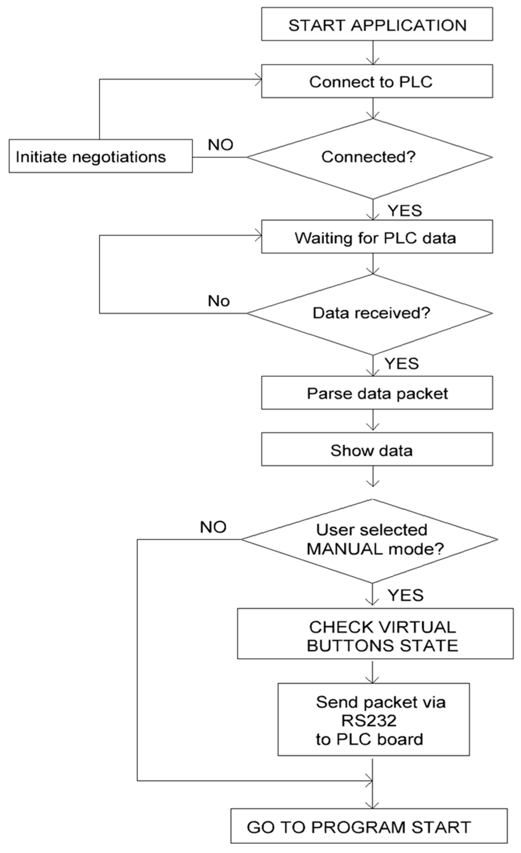
A thorough analysis of the data is conducted, and if no deviations from the set parameters are detected, the system is set into operation, granting the operator access to input working parameters via the application. Throughout each stage of data packet transmission, a thorough check is performed to ascertain the successful reception of the data. The control application is designed to function autonomously for extended periods without requiring operator intervention. Communication between the primary control board and the application is facilitated through RS 232 interfaces.
The application program operates in a closed loop, wherein, following an assessment of the system status and execution of operational instructions, it returns to its initial state, waiting for new input data. Additionally, the application includes the capability to monitor the vibration frequency of the vibratory feeder system and quantify the level of sinusoidal signal modification in percentage terms. The percentage representation corresponds to the area under the portion of the sinusoidal signal graph, a parameter that, as previously mentioned, is subject to control through the manipulation of the thyristor. The algorithm of the program is presented in
Figure 4.
As already mentioned, a PIC family microcontroller was used to control the vibratory dosing system. The control program for the microcontroller is written using the programming language C. A block diagram of the algorithm for this program is presented in
Figure 5.
In the first stage, the program is started by executing the START FIRMWARE command. Next, the initialization process and connection to the computer, which contains the control application, takes place. Then it is checked whether the PT-100 values of the temperature sensors are set correctly. Next, the states of the inputs are checked. After receiving the new data packets with settings from the application, the data are analyzed and system control parameters are adjusted (if they were changed in the operator control application). A certain state of system readiness is indicated by lit LED indicators. If the control program determines that the control system is ready for work and there are no deviations, it is allowed to modify the sinusoidal signal by changing its shape and area.
In the next step, the vibratory feeder is started at a maximum frequency of 50 Hz and an approximate weighing of the dosed production takes place. During the weighing, if the lack in the exact amount of production is determined, the frequency of mechanical oscillations of the vibratory feeder is adjusted accordingly, and production dosing and accurate weighing are performed [
2]. After reaching the required mass value of the dosed production, the vibratory feeder system is stopped. Next, the valve is opened and the product is poured into the package. After the complete dosing operation, the control program returns to the initial state and the dosing cycle is repeated.
For the implementation of the vibratory dosing system, a printed circuit board (PCB) was designed and manufactured, the general view of which is presented in
Figure 6. One side of the PCB is for connecting the microcontroller and other additional components, and the other side of the PCB is for connecting the boost registers and fast electrical contacts. In addition to the microcontroller, the printed circuit board has designed spaces for active SMD elements such as capacitors, diodes, etc. The PCB is manufactured using double-sided PCB manufacturing technology. The wiring tracks of the printed circuit board are made of copper layer. In order to prevent the copper tracks from oxidizing, the surface of the PCB was covered with a special dielectric material protecting it from environmental influences. In order to produce a PCB with the smallest possible geometric dimensions, optimization was carried out, which reduced the number of copper tracks and shortened their length.
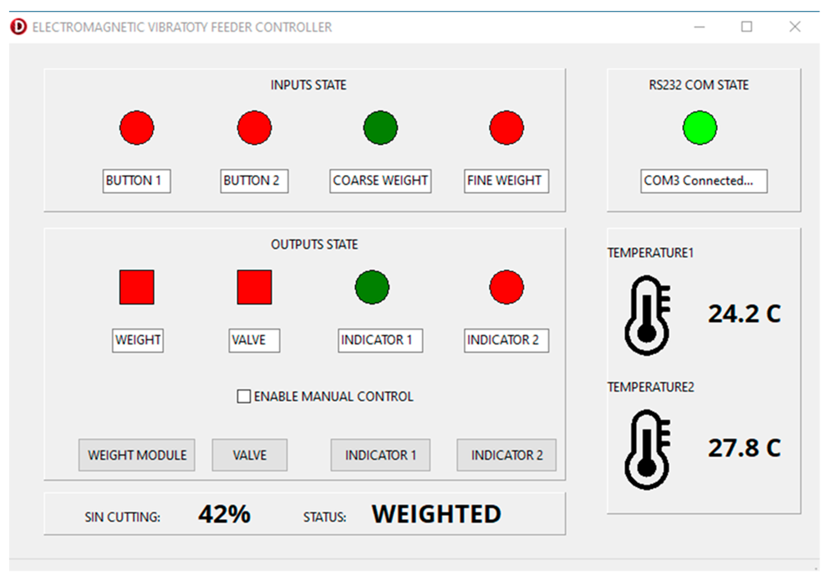
The accurate dosing of production is intricately tied to the precise control of the vibratory feeder system’s frequency and the modification of the sinusoidal voltage signal. For optimal functionality of the dosing system, maintaining consistent operating parameters, including vibration frequency and signal percentage area, is paramount. The system management application incorporates an active window that provides a real-time display of key technological process values. These values encompass critical metrics such as the temperature of the electromagnet and the percentage modification of the sinusoidal signal, among others.
Figure 7 illustrates the comprehensive overview of the control application window.
Upon configuring the necessary parameters for the technological process and initiating the system, the default mode is set to automatic operation. Consequently, the system can autonomously operate for the specified duration without requiring additional intervention from the operator. Furthermore, the application allows for the preservation of parameter values for future reference, ensuring consistency across multiple operational instances. Notably, the control application is equipped with a function that actively monitors deviations of technological parameters from established norms. In the case of any deviation, the operator receives immediate notifications to address and rectify the issue promptly. This proactive alert system contributes to the system’s reliability and aids in maintaining precise control over the dosing process.
Following the development of the vibratory feeder automatic control system based on sinusoidal signal modification, comprehensive tests were conducted to assess its performance. Digital resistors, specifically potentiometers with variable resistance, were employed to regulate the partial opening of the PN junctions of the thyristor. These digital resistors were automatically controlled through the PIC controller program. To quantify the modification of the sinusoidal signal, particularly the residual area of the graph corresponding to positive values, an oscillometer was utilized. The degree of modification was expressed as a percentage. The variable resistance of the digital resistor ranged from 1 to 120 kΩ, and the PIC controller program adjusted it accordingly. The results of these experiments are depicted in
Figure 8, showcasing the relationship between the percentage of the sinusoidal signal area and the control resistance of the thyristor.
The variation limits of the digital resistor’s resistance presented a broad spectrum, from 1 to 120 kΩ. The experimental measurements revealed a noteworthy trend—the dependence of the percentage of the sinusoidal signal area on the resistance exhibited an exponential-like pattern. Specifically, when the resistance of the potentiometer approached 1 Ω, an unmodified sinusoidal voltage was accurately obtained. Conversely, as the resistance of the potentiometer increased towards the range of 110 to 120 kΩ, the percentage of the sinusoidal voltage area approached zero. These findings emphasize the system’s capability to finely adjust the vibratory feeder’s performance by dynamically manipulating the thyristor’s control resistance. The observed exponential relationship signifies a nuanced and highly controlled response in altering the amplitude characteristics of the sinusoidal signal, providing valuable insights for optimizing the system’s efficiency across a broad range of operating conditions.
The comprehensive assessment of the automatic vibratory feeder system focused on understanding the relationship between the frequency of mechanical vibrations and the modification of the sinusoidal voltage. This relationship was visually represented in
Figure 9, where it was observed that the alteration of the sinusoidal voltage, expressed as a percentage change in the area under the graph of positive values, closely follows a linear trend [
2,
3]. The linear correlation discovered in the experiment is significant, indicating a consistent and predictable connection between the frequency of mechanical oscillations and the modification of the sinusoidal voltage. The linear trend suggests that incremental adjustments in the sinusoidal voltage modification parameter (partial area) within the range of 10% to 100% correspond proportionally to changes in the frequency of mechanical vibrations, ranging from 1 to 50 Hz.
This finding is crucial for system calibration as it allows for precise control over the vibratory feeder’s operational frequency. By manipulating the sinusoidal voltage modification parameter within the specified percentage range, operators can effectively regulate the frequency of mechanical vibrations. The linear correlation implies that as the sinusoidal modification parameter undergoes a shift from 10% to 100%, the frequency of mechanical vibrations undergoes a proportional change from 1 to 50 Hz. The proximity of this relationship to a straight line reinforces the idea that incremental adjustments in the sinusoidal voltage modification consistently and predictably correspond to changes in the frequency of mechanical vibrations. This insight provides a foundation for establishing a well-defined control framework, enhancing the system’s reliability, and optimizing its performance across various operational scenarios. In practical terms, this means that operators can rely on a linear relationship to fine-tune the vibratory feeder’s frequency based on their specific requirements, contributing to a more efficient and controlled operation.
Measurements were made with an accuracy of 0.5 Hz. In addition, a slightly faster increase in the mechanical frequency is seen at a fractional area of the supply voltage amplitude of less than 20%. This can happen due to the inertia of the system.
The results show that when the sinusoidal signal modification changes, the mechanical frequency also changes without any deviations, which is important for ensuring accurate production dosing in this type of systems.
During the testing of the vibratory feeder system, the flow rate of the dosed production was measured and its dependence on the mechanical vibration frequency of the system was evaluated. For the tests of the system, peanuts were selected, the transported amount of which was entered into the program management application. The dependence of the flow rate of the dosed production on the frequency of mechanical oscillations is presented in
Figure 10.
The precise measurements of the dosed amount of the product and its flow rate were realized through the implementation of the weighing method, ensuring a high degree of accuracy with an error of ±0.1 g. This approach enabled the assessment of the dosed product’s flow rate under various conditions, providing valuable insights into the system’s performance. The obtained results indicate a direct correlation between the frequency of mechanical oscillations and the flow rate of the dosed product. Specifically, as the frequency varies within the range of 0 to 50 Hz, the flow rate demonstrates a linear and proportional increase from 0 to 100 g/s. This observed linear relationship indicates that incremental adjustments in the frequency of mechanical oscillations correspond to changes in the dosed product’s flow rate. For systems designed for precise dosing applications, such as the vibratory feeder system under consideration, maintaining a stable and controllable change in the amount of dosed production is very important. The ability to achieve a linear and stable correlation between the frequency of mechanical oscillations and the flow rate of the dosed product highlights the system’s reliability and suitability for applications demanding precision and consistency. This stability is crucial in various industrial processes where precise control over the dosing rate is a critical factor for maintaining product quality and process efficiency.
As discussed in the literature review, vibratory feeder devices that rely on voltage frequency modulation often encounter a challenge associated with inconsistent amplitudes of mechanical oscillations. This inconsistency poses a significant problem in maintaining uniformity in the flow rate of the dosed product. To address this issue, it was tried during the experiments to achieve and sustain a stable amplitude of mechanical vibrations at a specified level of 1.5 mm. The key objective was to overcome the problem of amplitude fluctuations in vibratory feeder systems controlled by varying the supplied voltage frequency. These fluctuations can lead to irregular dosing and compromise the overall precision of the dosing process.
Figure 11 presents the results of the experiments, specifically illustrating the modification of the relationship between the amplitude of mechanical oscillations and the power supply voltage signal. By controlling and stabilizing the amplitude at 1.5 mm, the vibratory feeder system demonstrates a more consistent and reliable performance in terms of mechanical oscillations. This achievement is crucial for ensuring the uniformity of the dosing process, as a stable amplitude directly contributes to a more predictable and controlled flow rate of the dosed product. The ability to maintain a steady amplitude under varying power supply enhances the vibratory feeder system’s reliability, making it suitable for applications where precise and consistent dosing is needed. This stability is a significant advancement, addressing a common limitation associated with vibratory feeders controlled by voltage frequency adjustments.
A comparison of electrical power of vibratory feeder systems (including the control system) of similar design and operation is presented in
Table 1 [
1,
2,
3,
4]. Instantaneous electrical power consumption depends on the operating mode. As can be seen from the table, the highest consumed electric power (300–1000 W) is the vibratory feeder system, whose control method is based on SKADA/PLC/Frequency [
3,
29,
30]. Meanwhile, the lowest electrical power of the system (200–500 W), whose automatic control is based on Microcontroller-based control/change of supply voltage amplitude area. It is this system that was developed and studied during this study.
The lower electric power (when the system control is based on Microcontroller-based control/change of supply voltage amplitude area) is determined by the fact that in this case the mechanical frequency of the vibratory feeder system is changed, while the amplitude remains constant. Meanwhile, in the case of all other discussed systems, not only the frequency of mechanical oscillations is changed, but also the amplitude. Hence, in order to achieve a higher amplitude of oscillations, a higher electrical power is required.
As can be seen from the results, the system works reliably and no instabilities in the flow rate of the dosed production were noticed. It is worth mentioning that this vibratory feeder system is universal, suitable for dosing any solid fraction production. Before the dosing and transportation process takes place, it is sufficient to enter the exact and approximate mass values of the dosed product into the application. In addition, the control of the vibratory feeder device using the modification of the sinusoidal power supply voltage allows to avoid many problems (instability of the amplitude of mechanical oscillations, difficult control of the flow rate of the dosed product, complex and expensive construction, etc.), which are typical for vibratory feeder devices controlled by changing the frequency of the power supply voltage [
1,
2,
3].
During the research, the authors managed to create a vibratory feeder system characterized by a constant amplitude of mechanical vibrations using a modification of the supply voltage signal (partially changing the signal area). The control of this system was developed on the basis of a microcontroller. In the future, there is a plan to create and study a vibratory feeder system based on a PLC (programmable logic controller) using the method of partial variation of the supply voltage area. By using a PLC, it might be possible to eliminate the complex design phase of electronic circuits.
3. Materials and Methods
An electronic system based on PIC microcontrollers was developed to automatically control the bulk production vibratory feeder. Peanuts as a transported material were chosen for testing the vibratory feeder. During the process, there was an approximate and accurate weighing of the dosed production using a system consisting of a hopper into which the production was poured, a scale and a production release valve. The weighting module is controlled by a discrete 20 V signal. For vibratory dosing, the TARNOS FB-1 B (vibratory feeder) module (Tarnos, Madrid, Spain) was used, which consists of two main components: an electromagnet and a mechanical spring system. The technical data of this module are: weight—9.5 kg, flow rate—2 tm/h, and amplitude—1.6 mm.
PT-100 sensors were used to both monitor the ambient temperature and to measure the temperature of the electric coil of the vibration module. A piezoelectric vibration sensor DK-300 with a measuring amplitude in the range of 0–200 mm/s and with measured frequency limits of 1–1000 Hz and analog output of 4–20 mA was used to determine the mechanical frequency and amplitude of vibrations. The general conceptual diagram of the automatic control of the vibrating dosing system is presented in
Figure 12.
The main microcontroller used to control the system was PIC24FV32KA302 (Microchip Technology, Chandler, AZ, USA). A 16-bit microcontroller featuring eXtreme Low Power consumption is designed for power-constrained and battery-powered applications. It features unique peripherals like DSBOR, DSWDT and RTCC, which run in Deep Sleep mode for industry-leading low power performance. The power of the microcontroller is about 12 mW in operating mode, while in sleep mode it is about 5 µW. The C programming language was used for programming the microcontroller, while the control application was developed using the Delphi programming language. To realize the electronic control system, a PCB was created in which a microcontroller, electronic relay SRD-05VDC (Songle, Ningbo, China), as well as a set of necessary capacitors and resistors were soldered. The thyristor BTA16 (STMicroelectronics, Geneva, Switzerland) was used to modify the electric voltage amplitude of 220 V and 50 Hz (the oscillation frequency of the vibratory feeder depends on the modification), the control of which was carried out using a galvanic decoupling circuit with the MOC302 module (Onsemi, Phoenix, AZ, USA; electrical signals are transmitted using a modulated light beam). A plastic housing was designed and printed using a 3D printer to install the electronic control system.
This study was carried out in stages. An electronic circuit was created to control the vibratory feeder system using the already-listed details. A unique algorithm of the program was created for control, which allows to ensure a constant amplitude of mechanical vibrations and the flow of supplied production. The developed vibratory feeder system was tested and studied under real working conditions. The selected sequence of research stages allows to ensure work efficiency and highlight the operational advantages of the developed vibratory feeder system compared to similar systems.
The literature presents several alternative ways of controlling vibratory feeder systems: control using SCADA, control using feedback and microcontroller-based control systems. However, all control systems presented in the literature are based on changing the frequency of the supply voltage [
1,
2,
3,
4]. In addition, they have a fundamental drawback because they cannot ensure a constant amplitude of mechanical oscillations (for this reason, it is difficult to set the constant supply of the dosed production) [
29,
30]. The system presented in this study does not have this drawback.


