A Hybrid Maximum Power Point Tracking Method for Photovoltaic Systems for Dynamic Weather Conditions

Department of Mechanical Engineering, Jordan University of Science and Technology, Irbid 22110, Jordan
*
Author to whom correspondence should be addressed.
Resources 2018, 7(4), 68; https://doi.org/10.3390/resources7040068
Submission received: 14 September 2018
/
Revised: 8 October 2018
/
Accepted: 17 October 2018
/
Published: 2 November 2018
Abstract
:A hybrid MPPT (maximum power point tracking) controller integrates FLC (fuzzy logic controller) and P&O (Perturbation and Observation) method for MMPT of PV (Photovoltaic) under dynamic weather conditions is proposed. An adaptive neuro-fuzzy inference system is used to optimize parameters and membership functions of FLC. FLC is used to find the region of MPP (maximum power point); then, P&O technique is employed to accurately track the MPP. MATLAB/Simulink models are built to evaluate the performance of the proposed hybrid algorithm. In order to validate the performance of the proposed algorithm, comparisons with standalone FLC and P&O are carried out. The performance of the proposed algorithm is tested against dynamic weather condition. The results showed that the proposed algorithm successfully improve the dynamic and steady state responses of PV under severe dynamic weather condition. More specifically, the proposed approach shows its capability to attain the MPP faster than P&O and provided higher power than the standalone FLC. Finally, the proposed algorithm overcomes the limitations associated with FLC and P&O.
1. Introduction
In the presence of the global growing demand for energy, renewable energy sources provide the most promising alternatives. Among all other renewable energy resources, solar energy is the most plentiful and permanent [1]. The available solar power is 1.8 × 10¹¹ MW, which is far larger than the global energy consumption rate [2,3]. The photovoltaic technology is considered the most prominent method of utilizing solar energy. The power generated from PV (Photovoltaic) system depends on irradiance levels, temperature, shading, and other weather conditions. The MPP (maximum power point) varies with the radiation, thus the maximum power point MPP tracking algorithm is crucial to find and maintain maximum power levels. Using DC/DC convertors, PV generators are continuously being driven to operate at the voltage proposed by the algorithm to supply the load with the maximum available power.
Many algorithms were developed to drive PV generators to work at their MPP using the so-called maximum power point tracking (MPPT). The tracking algorithms are classified based on their functionality into direct and indirect methods. The indirect methods are based on experimentally obtained databases. Examples of these methods are curve fitting, look-up tables, open-circuit voltage method, short circuit current method, and the open-circuit voltage test cell method [4]. On the other hand, the direct methods are based on true measurements of voltage and current. Examples of direct methods are the conductance incremental method, differentiation methods, the perturbation and observe method, parasitic capacitance method, and the artificial intelligent methods [4].
It has been reported that P&O (Perturbation and Observation) is the most common method used in commercial products [5]. However, the P&O method has several drawbacks. Oscillating around maximum power point is the main drawback. Moreover, the conventional P&O techniques based on the fixed step size perturbation have many disadvantages [5]. It has been shown that small step size causes low oscillations during steady-state weather conditions but with slower response. On the other hand, larger step size leads to faster response but with higher oscillations at steady-state conditions. Moreover, the conventional P&O has two independent control loops, where it uses proportional-integral (PI) controller in one loop [6]. The PV systems are nonlinear and the PI controller is used for linear systems. The performance of such systems reduces significantly due to the random nature of weather conditions [7].
The main disadvantages of conventional methods are inaccuracy, large oscillations, slow convergence and getting trapped in local peaks. To overcome these problems, several modifications were performed on these conventional methods [8,9,10,11,12,13]. The dynamic changes in weather conditions (sudden changes in irradiations and partial shading) are considered a real challenge for MPPT algorithms. Multiple peaks appear in the power curves of PV module when subjected to partial shading conditions. To counter this phenomenon, many algorithms were proposed to distinguish the global maxima from the rest of the local ones [13,14,15].
The artificial intelligent systems are becoming increasingly desirable in tracking the global MPP due to their capability of dealing with the prominent nonlinearities in the I–V characteristics of PV systems [16,17,18,19]. In fact, the artificial intelligent techniques, though being with the highest complexity to employ, provide promising solutions and efficient flexible tracking algorithms capable of dealing with dynamic weather conditions. The fuzzy logic controller (FLC) gives a good performance under dynamic weather conditions. It showed better tracking under the partial shading conditions, faster convergence and lower oscillation about the global maxima [20,21]. Further enhancements could be achieved when employing the evolutionary algorithms (EA) such as genetic algorithms (GA), and neural networks (NN) in optimizing the fuzzy controller’s parameters and membership functions based on preselected training data [22,23,24].
Partial shading condition occurs because of trees, buildings, cloudy conditions, and self-shading. A PV system generates low power output due to the mismatch at these conditions. Several improvements on the conventional P&O algorithm have been proposed to enhance its performance under dynamic weather conditions [25,26]. An artificial neural network (ANN) was used to improve the performance of P&O technique in [25]. Fuzzy logic is used to improve the performance of P&O technique in [26] and increment of conductance in [27]. Radjai et al. modified the P&O (MPPT) method with an adaptive duty cycle step size using the fuzzy logic controller to enhance the response under dynamic weather condition [28]. However, their developed algorithms do not take into account the partial shading of PV arrays. D’Souza et al. used fuzzy logic and nonswitching zone schemes for implementing variable size perturbations to improve transient and steady-state responses [29]. Salah and Ouali compared the fuzzy logic and a neural network controller used for maximum power point tracking for PV systems [30]. Their results showed that the fuzzy logic controller can deliver more power than the neural network controller and can give more power than other different methods in the literature. Algarín et al. evaluated the performance of the FLC controller with under sudden changes in operating temperature and solar irradiance [31]. The results showed that the fuzzy controller has an excellent performance under sudden changes in the operating temperature of the PV module, in contrast with P&O control that is considerably affected, presenting significant power losses.
Although fuzzy control has good ability dealing with the nonlinear system, but its main drawback is the generated a cumulative error due to continuous integral calculus [32]. Most FLC-based MPPT techniques take the error (e(t)), and the change in error (de(t)/dt) as inputs. However, the requirement of differentiation not only increases the complexity of calculation, but also may induce large amounts of errors from merely small amounts of measurement noise [33]. Various techniques are proposed to further improve the conventional FLC’s performance [34,35,36]. For example, ANN is applied to assist FLC in with solar irradiance and cell temperature as the input variables. However, ANN technique needs a great amount of training data to acquire reasonable results, which could limit its application [33]. Moreover, methods which were proposed to enhance the tracking speed of FLC, hard to be to realize using low-cost microcontrollers compared with conventional FLC. On the other hand, Algarín et al. presented a low-cost MPPT system based on neural network inverse model controller [37]. Simulation results demonstrated the superiority of a neural controller over the P&O.
Several hybrid MPPT algorithms have been proposed by many researchers recently [38,39,40,41,42,43,44] to deal with partial shading conditions. A hybrid controller combines the advantages of fuzzy logic and conventional PID control is proposed by [38,39]. Jiang et al. proposed a hybrid MPPT controller that combines ANN and P&O without irradiance sensor [40]. ANN, which is used to train several partial shading cases offline, is used to predict the region of MPP, then the P&O technique is employed to accurately track the MPP. Seyedmahmoudian et al. proposed a MPPT technique that employs a hybrid evolutionary algorithm, which combines particle swarm optimization (PSO) and differential evolution (DE) [41]. The proposed technique shows several advantages in the MPP tracking under partial shading conditions. Daraban et al. proposed an MPPT technique that embeds the P&O algorithm in genetic algorithms structure [42]. Each individual carrying an information of the reference voltage, the direction and the step value. Lian et al. presented a hybrid MPPT algorithm that combines P&O and the PSO method [43]. Initially, the P&O method is employed to locate the nearest local maximum. Then, the PSO method is employed to locate the MPP starting from that point. Sundareswaran et al. combined PSO and P&O MPPT algorithm [44]. In the first stage, PSO is used to locate the MPP. Then, the MPP tracking is performed using P&O method.
The main objective of this study is to develop an efficient MPPT algorithm that overcomes the problems with conventional methods under sudden changes and partial shading conditions. The developed algorithm should have higher efficiency, faster convergence and lower oscillation about the global MPP under severe weather conditions. The proposed algorithm is a hybrid combination between the fuzzy logic controller (FLC) and the conventional perturb and observe (P&O) method. It finds the MPP using P&O algorithm with a small step size initialized with a duty cycle obtained from FLC algorithm. Utilizing FLC rapidly brings the system to the vicinity of the MPP and allows the use of a small step size in the P&O algorithm for higher accuracy and lower oscillations. The performance of the proposed algorithm is investigated by building MATLAB/Simulink models consisting of the photovoltaic system, boost converter, and controllers. Fuzzy controller’s parameters and membership functions are optimized employing the adaptive neuro-fuzzy inference system (ANFIS). Comparisons against standalone FLC and P&O controllers are performed to assess the performance of the proposed hybrid algorithm.
2. PV Modeling and Characteristics
PV cells have p–n junction generating electrical power by using photons. It generates electricity when absorbing solar irradiance. When a load is connected to the PV cell, a direct current is generated until the irradiance gets stop. The PV cell is modelled using the single diode model. The model comprises a current source, a diode, a series resistance, and a shunt resistance. The characteristic equations of PV cell are found in [45,46]. Typically, the generated voltage from one cell varies from 0.5 to 0.8 V depending on the manufacturing technology. To boost this low voltage and make it more useful, dozens of PV cells are connected in series forming the PV module [47]. Based on the single diode model, the output current of the photovoltaic module Ipvm is [46]:
where, IPV is the current generated by the cell, Iph is the solar generated current, Ish is the shunt resistance current and ID is the diode current, q is an electron charge (1.6 × 10⁻¹⁹ C), T is the cell’s operating temperature, Kb is the Boltzmann’s constant (1.38 × 10⁻²³ J/K), A is the diode ideality factor, Rs is the series resistance, VPV and IPV are the photovoltaic operating voltage and current respectively, IDS is the diode saturation current. Equation (1) is modeled in MATLAB/Simulink employing 72 cells connected in series based on the electrical specifications provided by SUNTECH STP270-24/Vd PV module datasheet shown in Table 1.
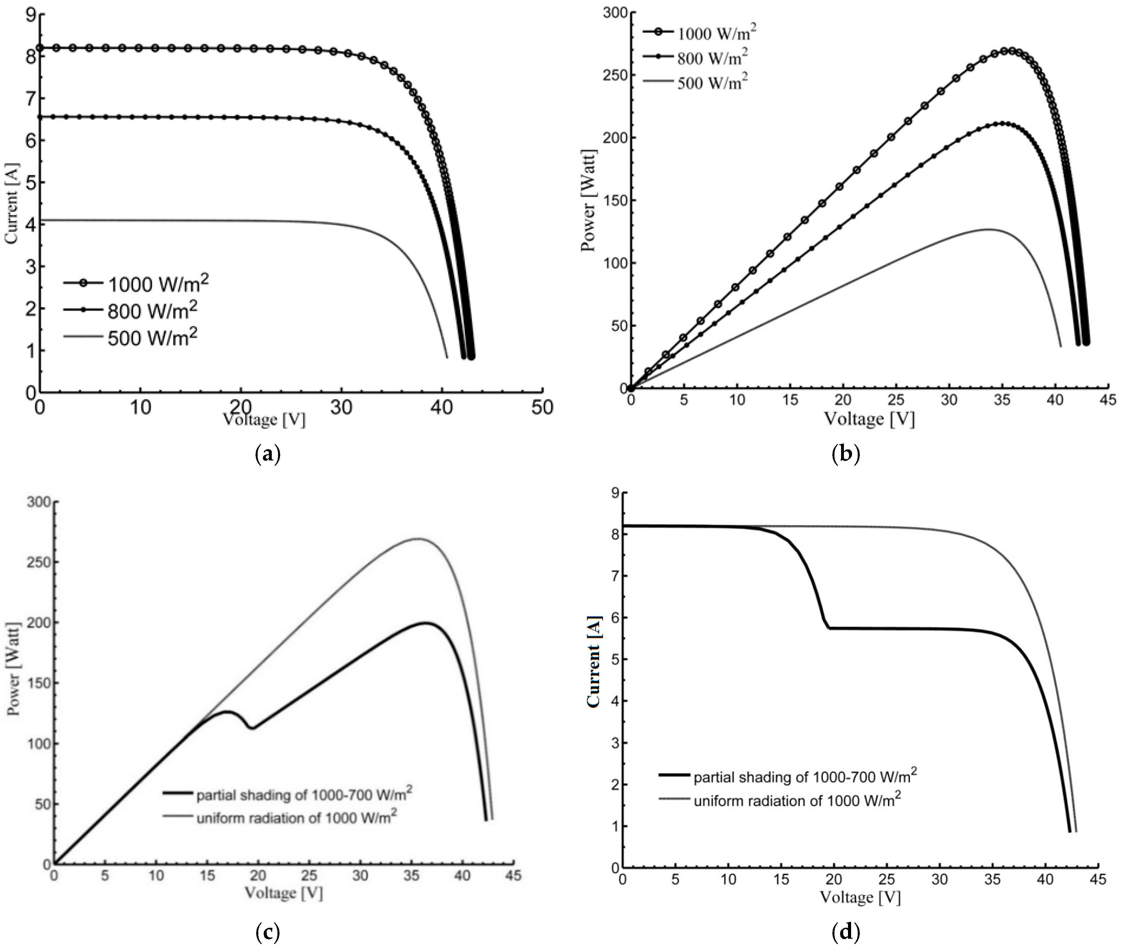
MATLAB and Simulink have been successfully used for modelling and simulations of PV systems. The simulations models for I–V and P–V curves are in a good agreement with experimental tests for different operating conditions and array setup configurations [48]. The typical P–V and I–V nonlinear characteristics of the PV module are shown in Figure 1. As can be seen from the curves in Figure 1, maximum power occurs at a unique point called maximum power point MPP. MPPT is used to make the system operate at this specific point. The partial shading occurs when a part of the system experiences some shadowing. Multiple peaks appear in the PV characteristic when the system is subjected to partial shading conditions as shown in Figure 1c,d. The existence of multiple peaks provides a real challenge for MPPT algorithms.
As shown in the P–V characteristic of the PV array, it’s clear that any change of the voltage delivered to the load results in a change of the power produced by the PV module. To track the maximum power point, an electronic device called boost convertor is usually inserted between the PV generator and the loads to control the voltage extracted by module without the need of continuously changing the load. The output voltage of the boost convertor is controlled using a train of pulses produced by a pulse generator. The duty cycle D of the generated pulse width modulated signal relates the output voltage Vo to the input voltage Vi as:
3. MPPT Algorithms
MPPT algorithms are implemented to find the optimal duty cycle to maintain the maximum power levels of PV systems.
3.1. P&O Algorithm
The detailed description of P&O can be found in [4]. The flow chart of the P&O algorithm can be summarized as follows; after recording the present power levels produced by the system, the algorithm performs a perturbation to the operating point by means of changing the duty cycle and measures the resulting power accordingly. If there is an increase in the power levels, iteration is performed in the same direction. Otherwise, iteration in the reverse direction is carried out. The peak is detected when the power oscillates about a certain value, i.e., increasing and decreasing the duty cycle result in less power levels.
3.2. Fuzzy Logic Controller (FLC)
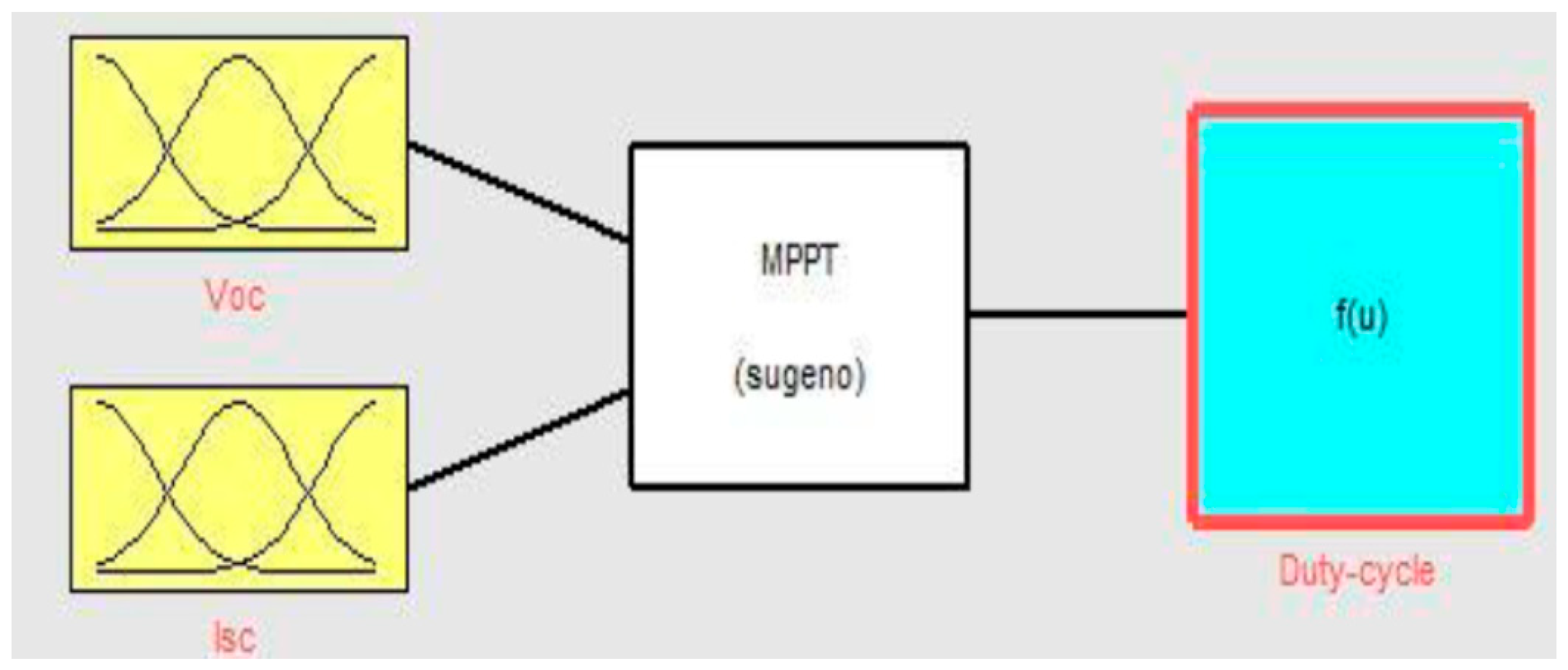
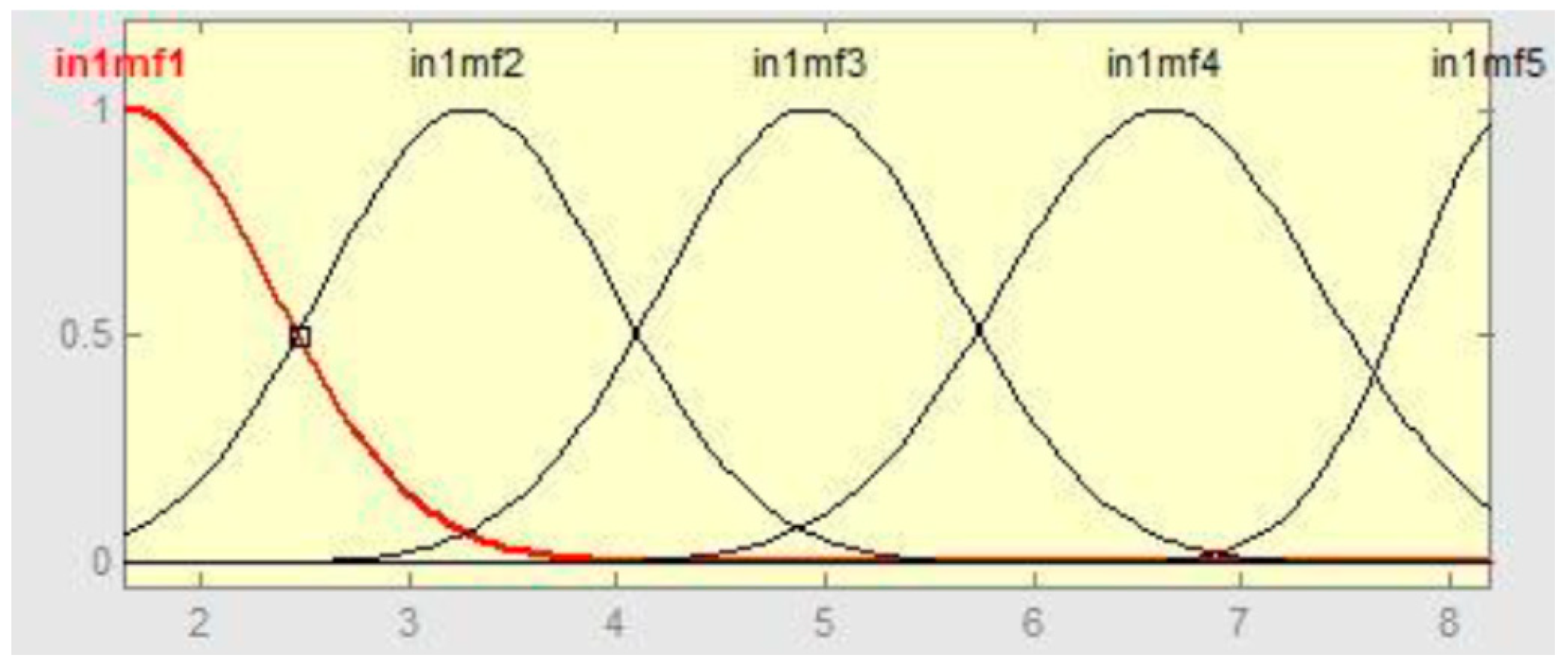
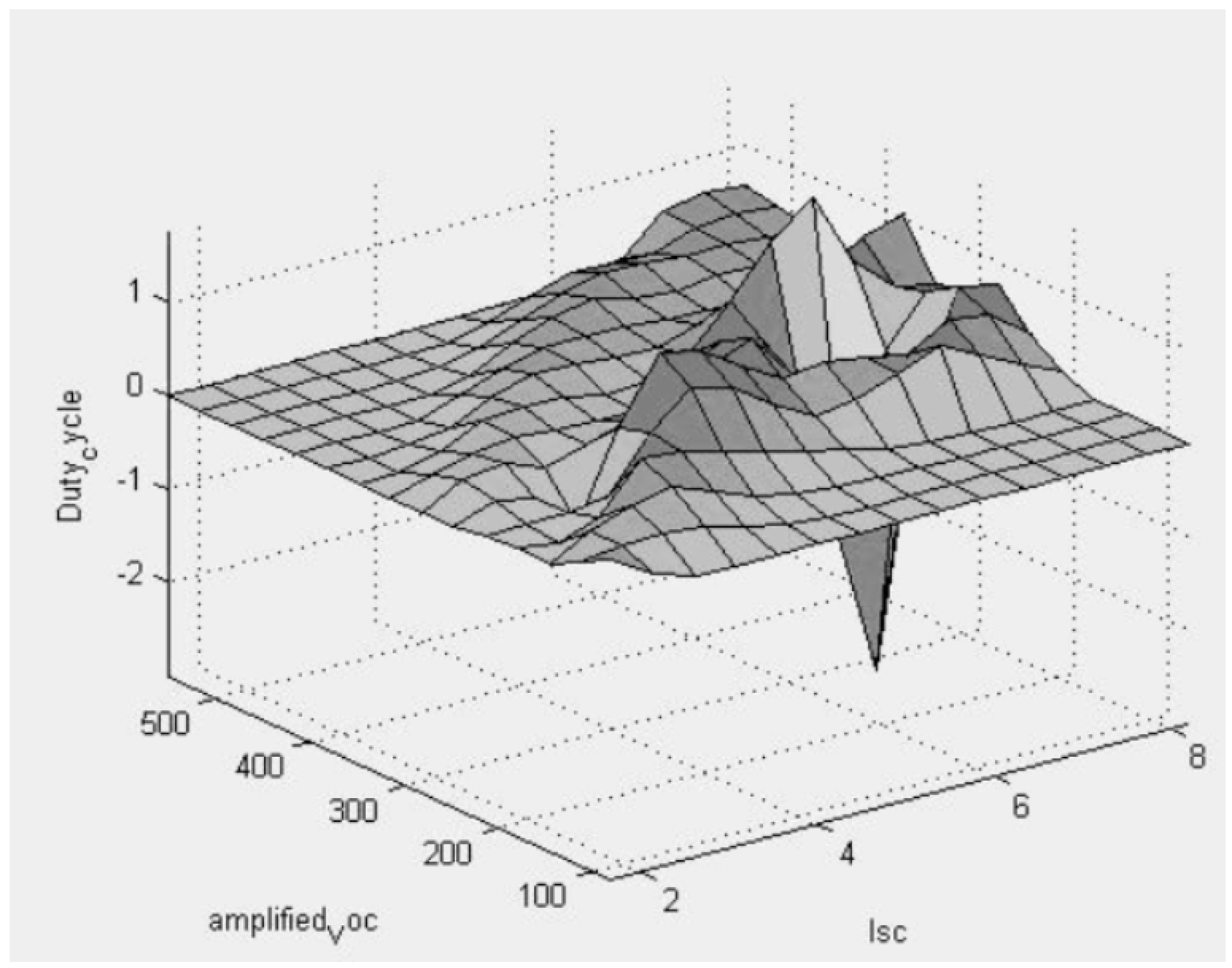
The fuzzy logic deals with partially true variables ranging between fully false and the fully true. The fuzzy based controllers can effectively deal with the nonlinearity in the I–V characteristics of PV systems. It forms an approximation that maps input values to their predicted outputs based on IF-THEN rules. The fuzzy logic controller is operated using membership functions instead of the mathematical model. It consists of three stages: fuzzification, inference mechanism, rule-based table look-up and defuzzification. It has two inputs (power and ∆V) and one output (D). As shown in Figure 2, the generated inference system consists of two inputs (open circuit voltage and short circuit current) and one output (the desired duty cycle). Each input comprises five Gaussian type membership functions as shown in Figure 3. Figure 4 shows the surface generated for the fuzzy controller.
The fuzzy controller proposed in this paper is built using an adaptive neural network for a Sugeno-type fuzzy model. We choose this model because it is less time consuming and more transparent than other fuzzy models. The adaptive neuro-fuzzy inference system (ANFIS) generates rules and membership function parameters and tune them based on a given input–output data set. In order to train the neural network and tune the fuzzy controller parameters, a set of input-output data is obtained manually using MATLAB/Simulink models. Two models were used; the first one not shown was used to record the maximum available power at each insolation level ranging from 100 to 1000 (W/m2) in partial and full shading conditions. The second one not shown was used to seek the optimum duty cycle manually in an iterative manner and to record the corresponding open circuit voltage and the short circuit current. Fifty-five input–output data sets are finally produced. It is worth mentioning that these types of modelling work well if there are a large number of data to be used for training.
Adaptive neuro-fuzzy inference system (ANFIS) integrates fuzzy logic and neural networks. It has the potential to capture the benefits of both methods in a single framework. The neural networks NN algorithm is operated based on internal data training, while external data training is used for fuzzy logic algorithm operation. The tracking error and change in error are fed as input to the neural network while the NN output is fed as an input to the fuzzy system. The parameters used to train the FLC using ANFIS are listed in Table 2.
3.3. Proposed Hybrid MPPT Algorithm
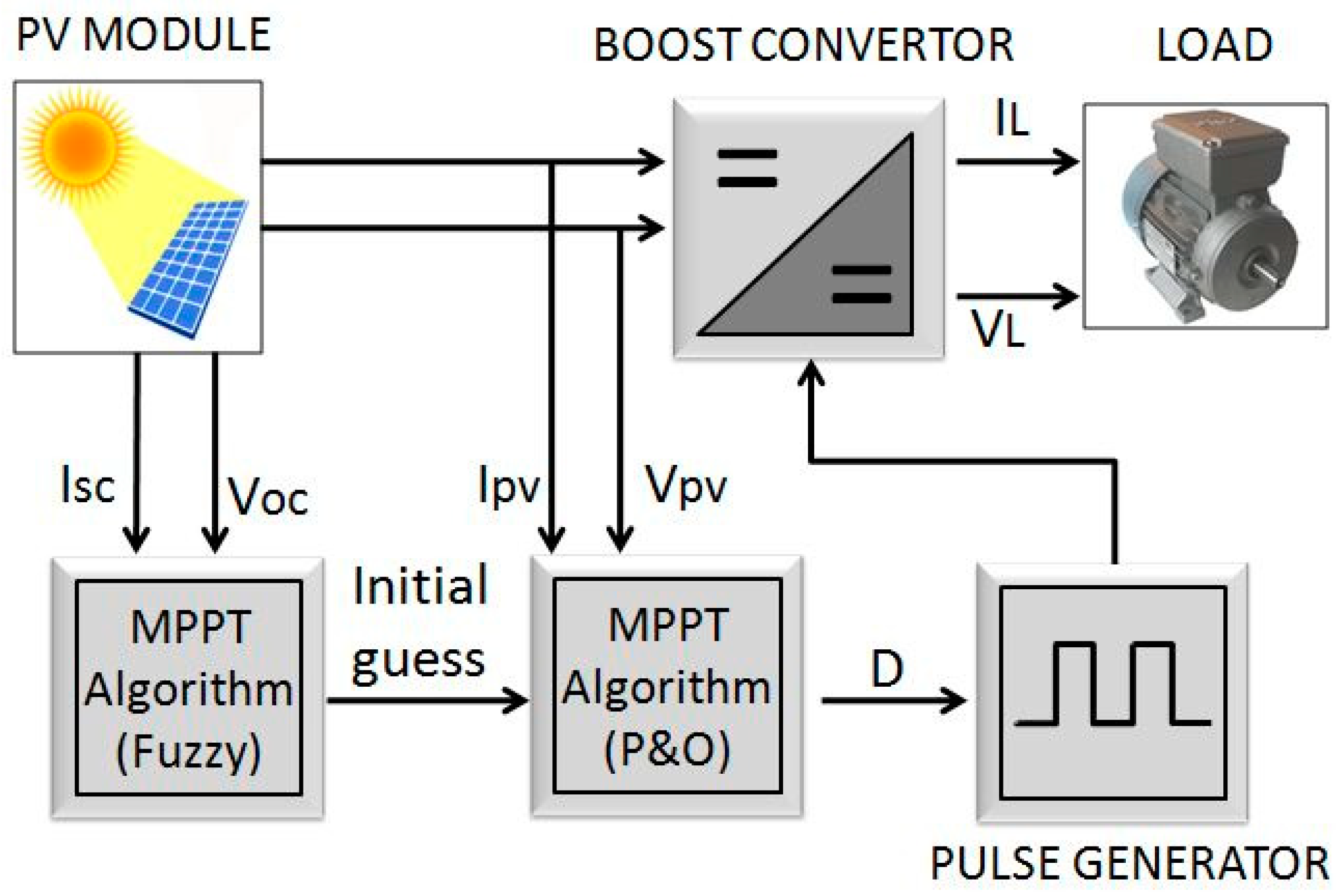
The main idea of the hybrid proposed algorithm is to take the advantages of the strength of both FLC and P&O algorithm in a single frame work. FLC can work under dynamic weather conditions with limited accuracy, while P&O algorithm can achieve high accuracy when using small step size. A high performance algorithm can be developed by using FLC to provide the P&O with initial guess in region of maximum power point. Therefore, the proposed hybrid algorithm combines the quickness of approximation from the fuzzy system with the accuracy of P&O method. Schematic diagram of PV system with hybrid MPPT used to build MATLAB/Simulink model is showing in Figure 5.
4. Results and Discussion
In order to validate the performance of proposed hybrid algorithm, a comparison between its performance with classical P&O method alone, and FLC alone is presented. To accurately investigate the performance of the FLC, tracking error, and tracking efficiency are defined [2]:
4.1. Performance of FLC Alone
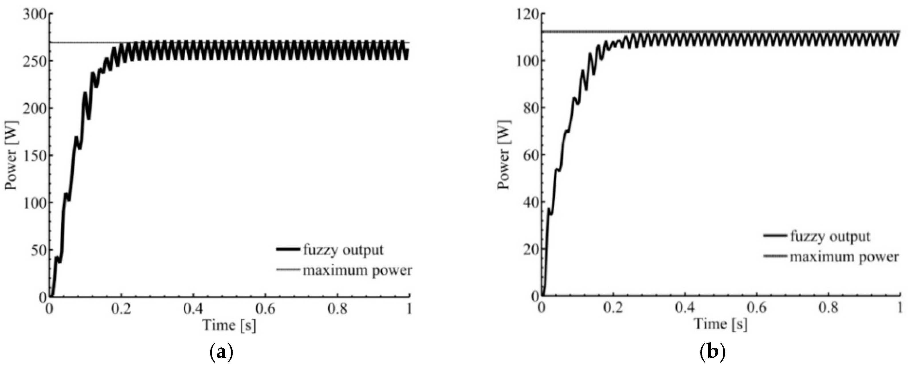
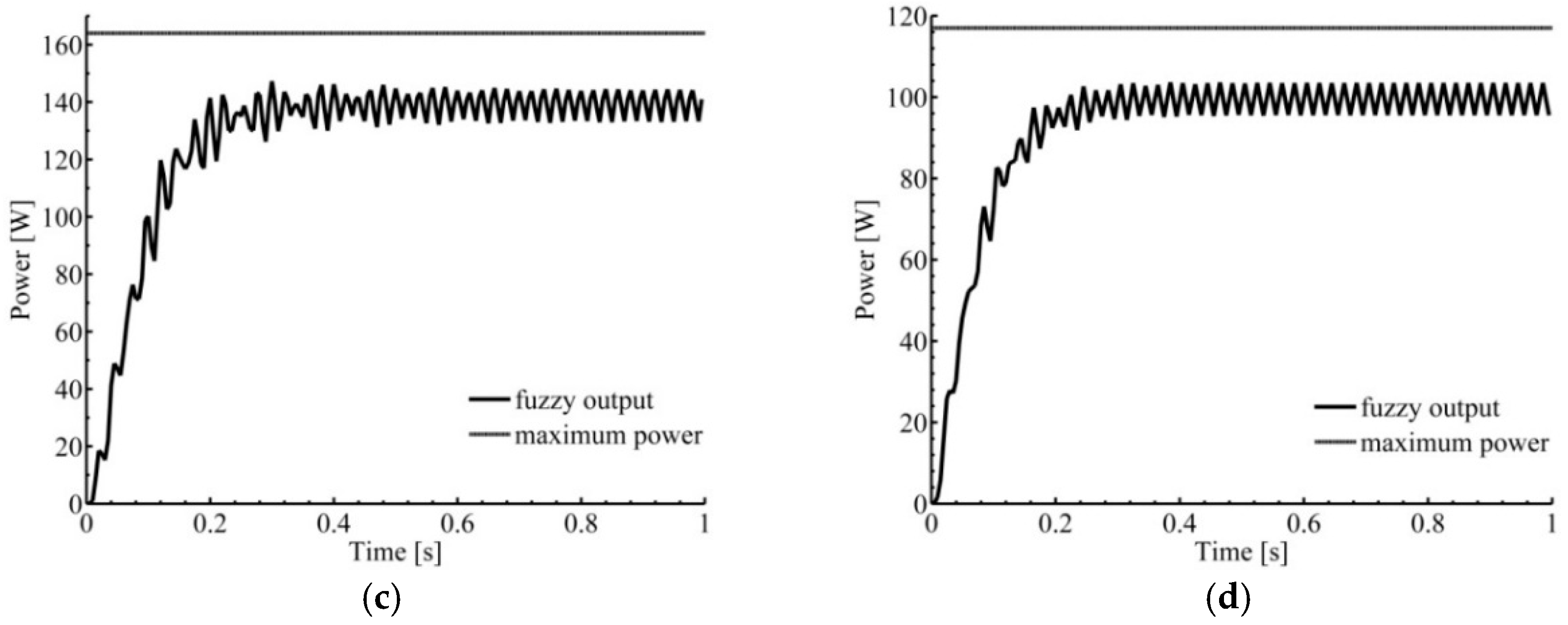
Fuzzy controller’s parameters and membership functions developed in this study are optimized by employing the adaptive neuro-fuzzy inference system (ANFIS). A training set of 55 data points are used. In order to evaluate the robustness of FLC algorithm under random weather conditions, two cases are simulated; (1) Assessing the performance at the same training data points; (2) Assessing at different points. Figure 6a,b show that the fuzzy controller was able to produce more than 97% of the available power when PV modules are tested at the same data point. On the other hand, testing far from trained data points, the FLC was able to harvest only 85% of the available power (see Figure 6c,d). This demonstrates that FLC is always capable of placing the system to the region of the MPP. It is worth mentioning that using large number of data for training is not practical to enhance the accuracy of FLC, because this required large number of membership functions that consume higher processing time. Table 3 further illustrates that FLC is efficient in harvesting power when weather conditions are the same trained data points and its efficiency decreases as weather conditions deviates from these points. Finally, the curves presented in Figure 6 show that the FLC has fast convergence around the desired MPP, i.e., it reaches the MPP in less than 0.25 s in all cases.
4.2. Performance of P&O Alone
The step size of the P&O method affects the performance greatly due to its iterative nature. During iterations, the current duty cycle changes either up or down. To illustrate the effect of step size on the performance of P&O algorithm, two step sizes were simulated under uniform shading conditions. It can been see in Figure 7a that increasing the step size leads to faster convergence, but on the other hand leads to wider oscillations. On the other hand, using small step size enhances power output and reduces oscillations. This behavior can be explained as follows; using large step size can cause overstepping local maxima, hence, less efficiency and wider oscillations about the peak power comparing to the case of using small step size.
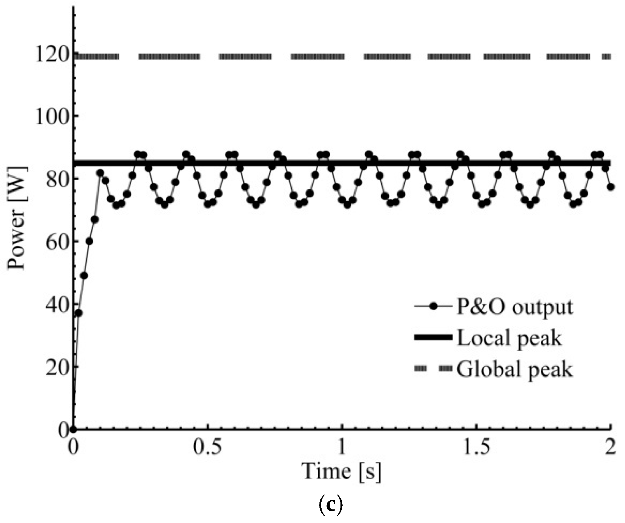
Partial shading occurs when some portions of the PV array experience different irradiation levels, more than one peak appear in the P–V characteristics and many local maximum power points exist. Among these power points, only one is the maximum power point, i.e., global peak. Due to the nature of P&O method, searching starts for the closest peak by changing the duty cycle that is originally set to zero. Therefore, the algorithm recognizes the maximum power point associated with the least duty cycle even if it is not the global peak. On other words, the algorithm might get trapped in the local peak. It continuously oscillates around the first peak found which is not necessarily the global. To demonstrate this phenomenon, partial shading conditions are applied to the PV system by dividing the PV panel into two portions each with different radiation level. Figure 7b,c shows that P&O got trapped in a local maximum under partial shading conditions of (1000, 300) W/m2.
4.3. Performance of the Hybrid Proposed Algorithm
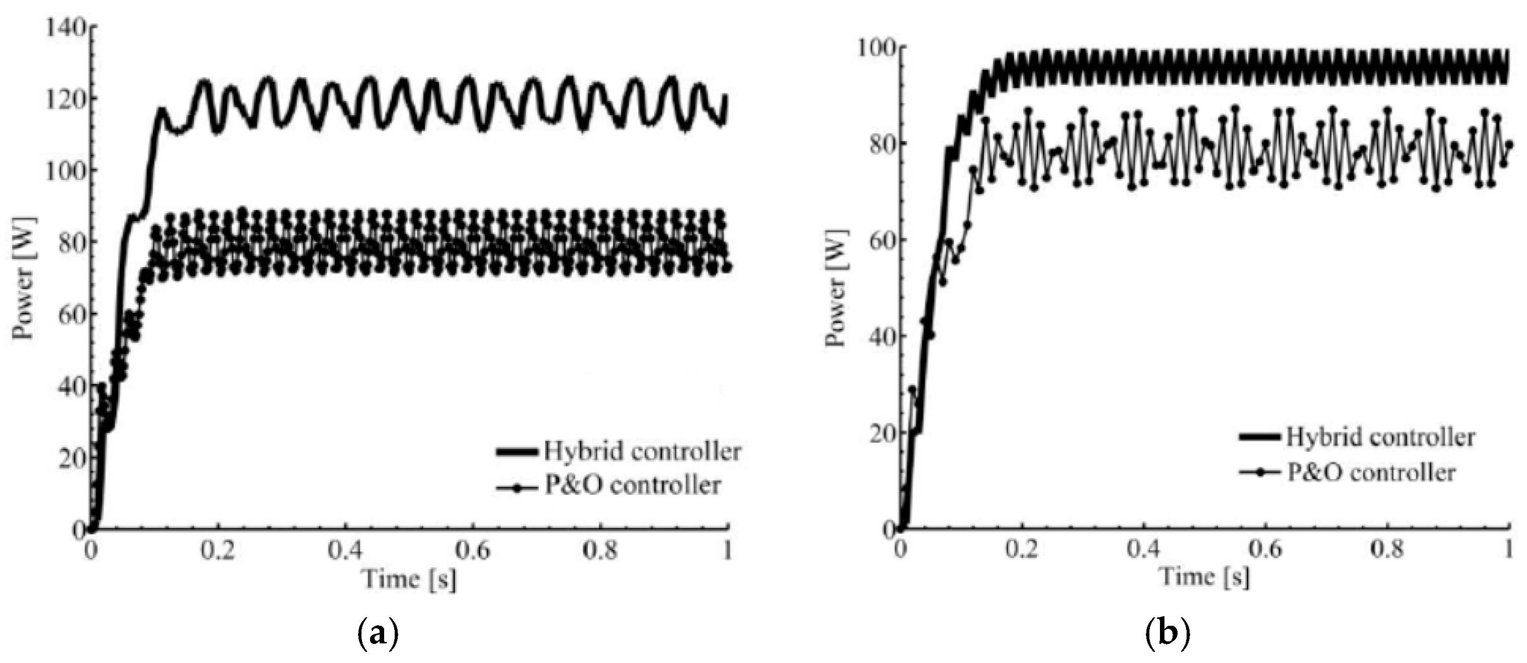
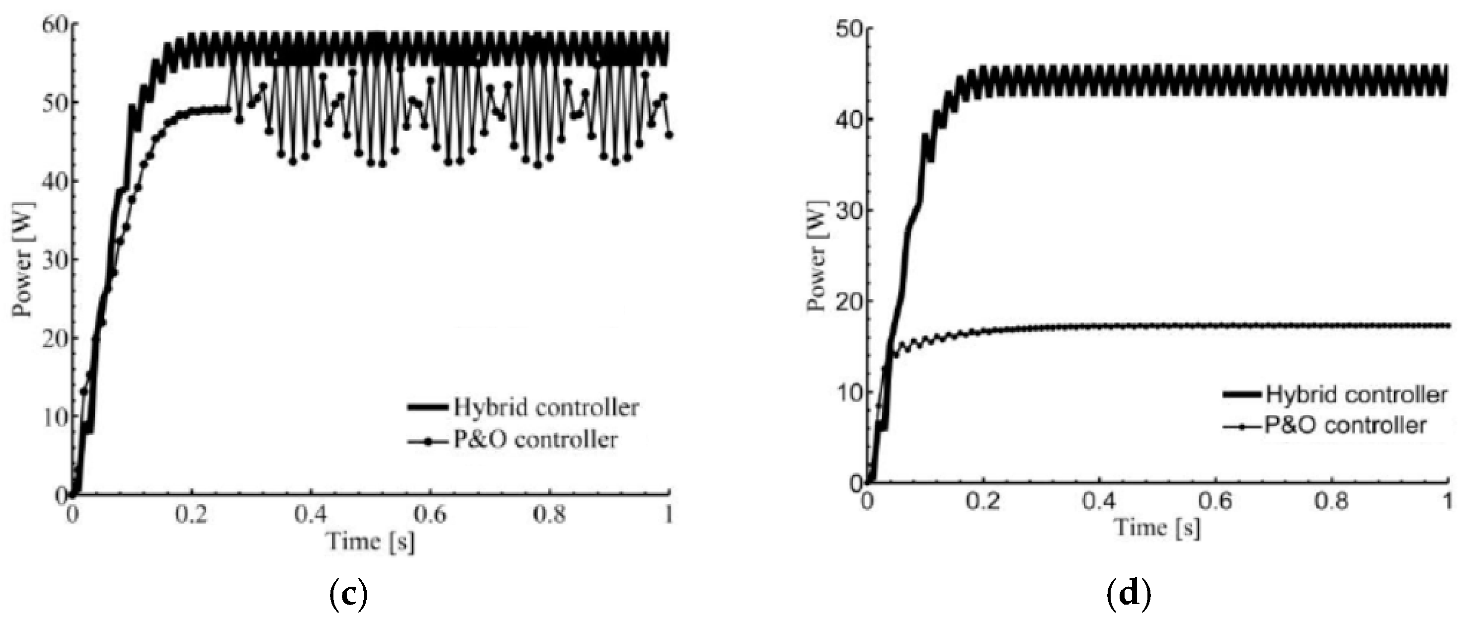
The performance of the proposed hybrid algorithm under three weather conditions is assessed. These conditions are (a) uniform condition; (b) partial shading; (c) sudden changes. The performance of the hybrid algorithm is compared against FLC alone, and P&O alone. Several uniform conditions are simulated and the results are presented in Figure 8. It can be seen in Figure 8 that all algorithms approach MPP under uniform conditions. Moreover, the hybrid algorithm has faster response and has the ability to deliver more power than P&O. P&O can deliver higher power if decreasing the step, size which is unavoidably accompanied by a slower response.
To further evaluate the performance of the proposed algorithm, several partial shading cases are simulated. Figure 9 shows the performance of the hybrid controller under several partial shading conditions. For all simulation cases studied, the hybrid controller successfully finds the global maximum power point while the P&O got trapped in the local MPP. As mentioned earlier, the fuzzy controller always finds the duty cycle that brings the system to the vicinity of the global MPP. The P&O part of the hybrid controller uses this duty cycle as an initial guess to further increase the power obtained by the PV module.
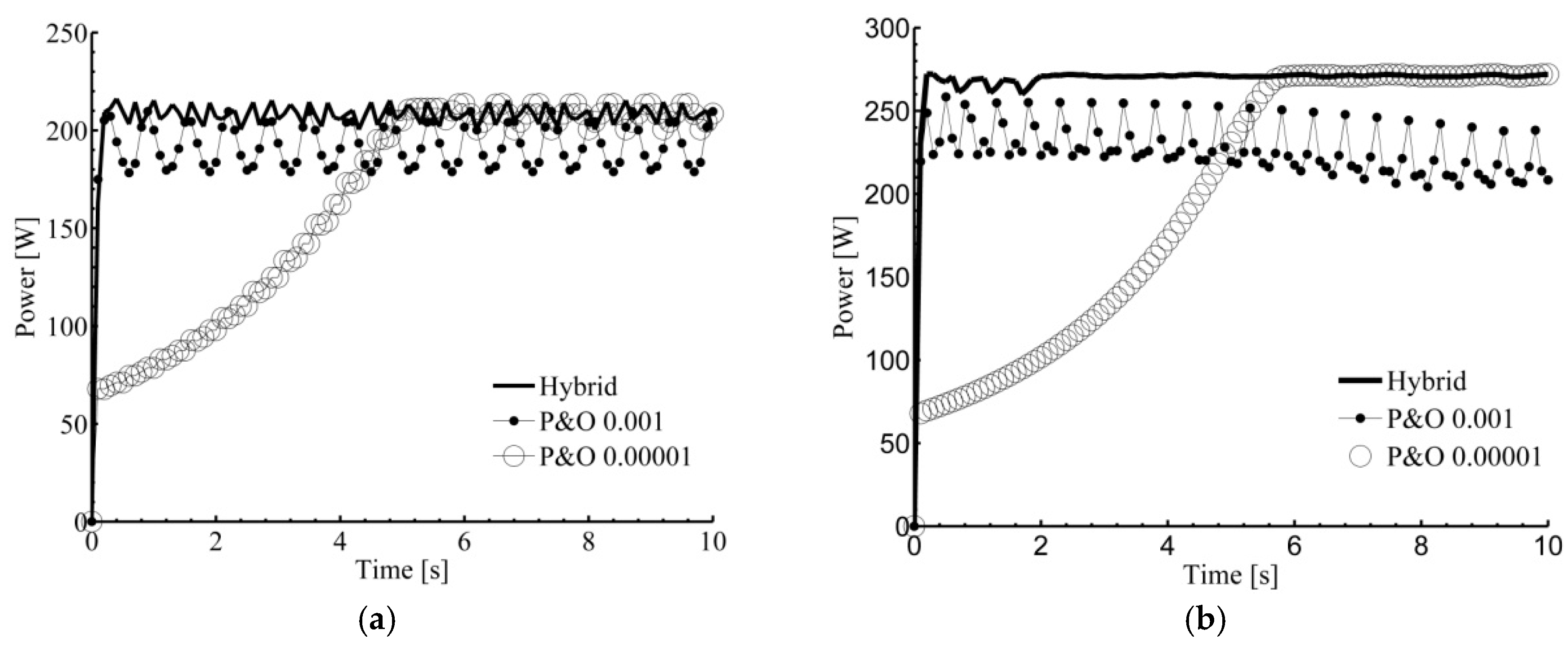
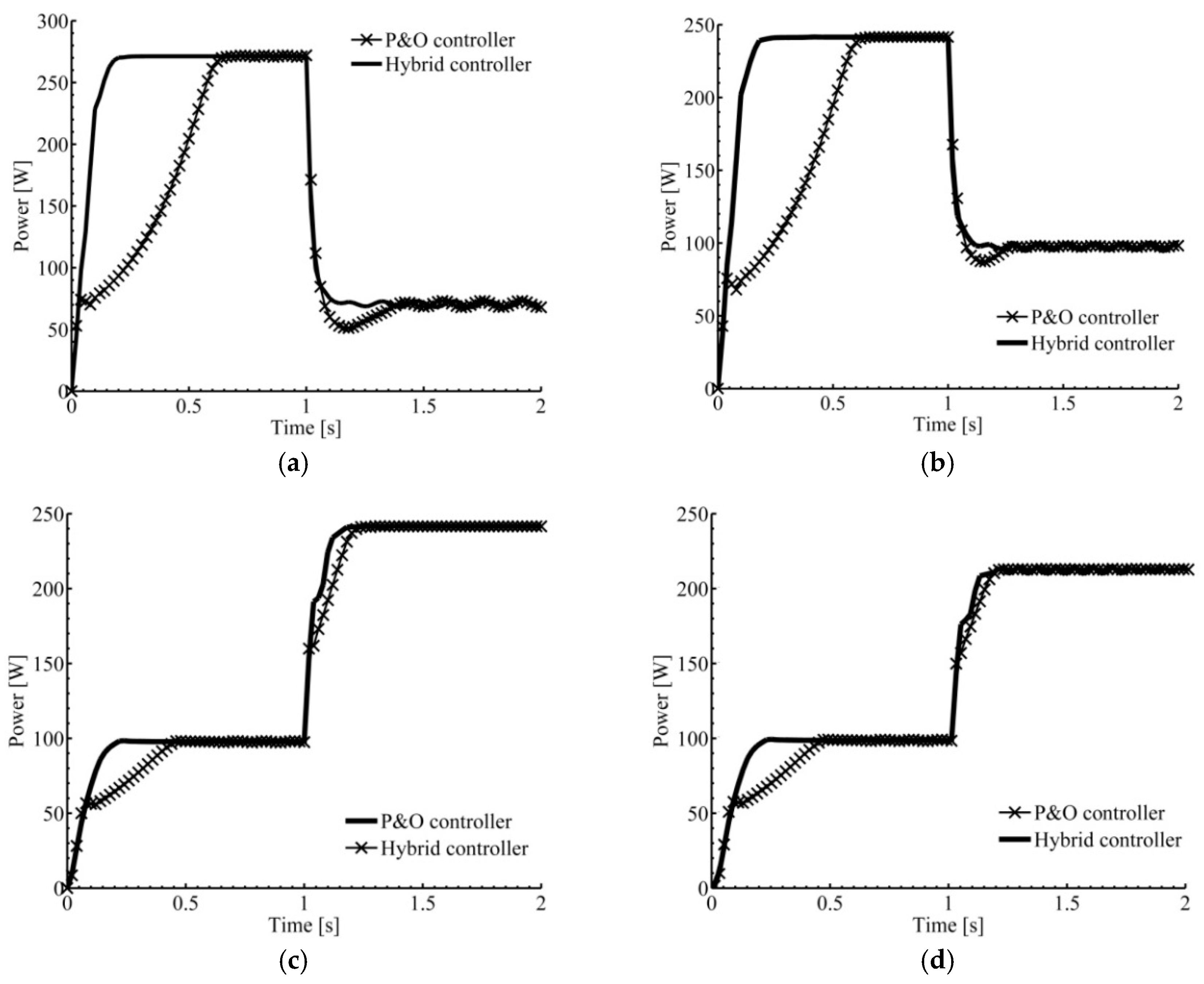
The P&O algorithm has a relatively long recovery time when exposed to sudden changes in radiation levels. To assess the proposed algorithm under this condition, several simulations are conducted by replacing the constant irradiation input of the PV model with a step signal. The results showed in Figure 10 show that the proposed algorithm rapidly finds the new MPP. For example, Figure 10a shows the performance when the radiation changes from 1000 W/m2 to 700 W/m2, the power obtained from P&O controller changed from 259 W to 70 W in 0.4 s while it took only 0.15 s for the proposed controller to change the power from 267 W to 72 W. Table 4 lists comparisons between P&O with different step sizes, Fuzzy and the proposed hybrid controllers. It is clear from simulation results listed in Table 4 that the proposed hybrid controller successfully outcome the shortages of fuzzy and P&O algorithm alone.
4.4. Testing the Performance at Random Weather Conditions
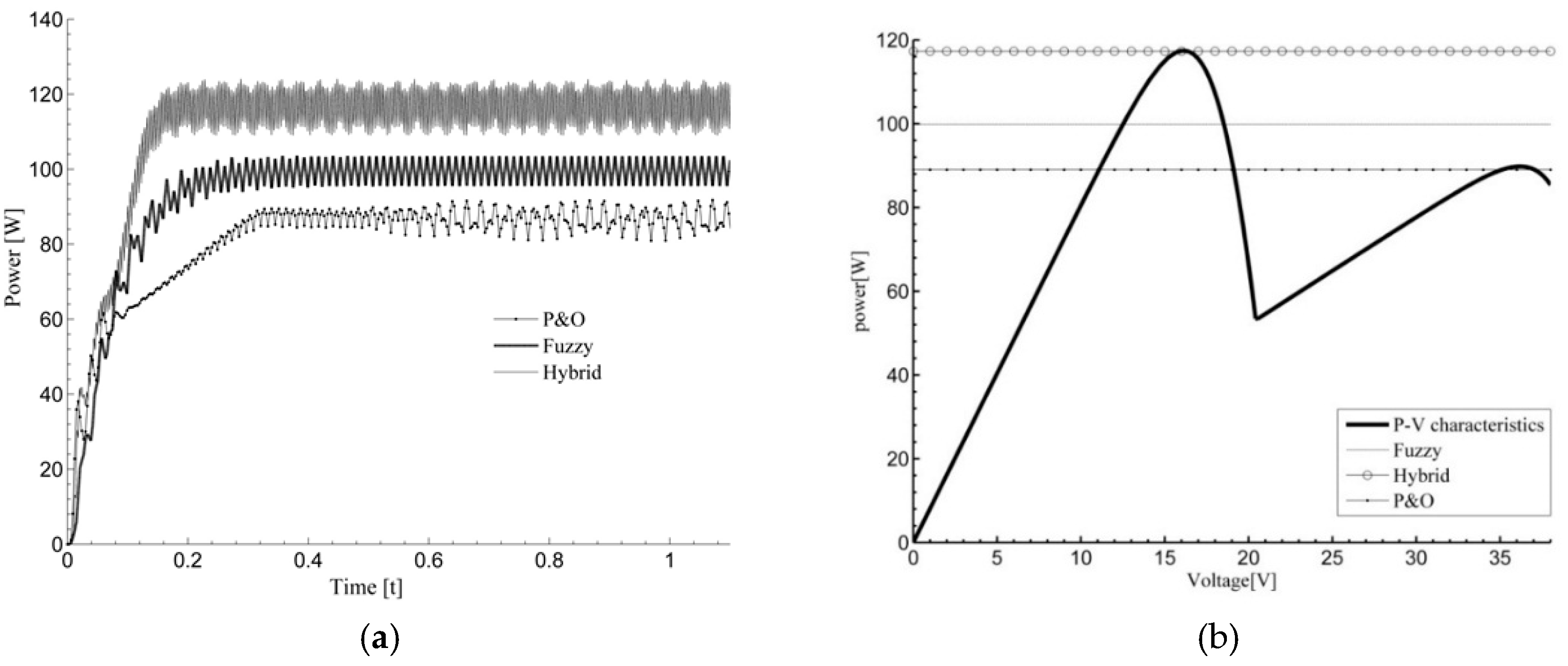
FLC requires large number of training data points to work well. Fuzzy controller generated using adaptive neuro-fuzzy inference system is found highly accurate when tested at the same data points that were used for training it. Otherwise, its accuracy decreases significantly when tested far from those points. It is worth mentioning that using large numbers of data for training is not practical to enhance the accuracy of FLC, because this required large number of membership functions that consume higher processing time. To clarify this point, we simulated partial shading case where the amount of solar radiation is far from those implemented to train the fuzzy controller. Figure 11 shows the performance of the three algorithms when 36 cells of PV is subjected to 985 W/m2 and the other 36 cells are exposed to 317 W/m2. These weather conditions points were not utilized for training. It can be seeing in Figure 11 that that P&O got trapped in the local maximum i.e., local maximum power point is 89 W, where the global maximums power point for this weather condition is 118 W. Moreover, the accuracy of FLC was extremely low. i.e., FLC alone was only able to deliver only 84.5% of the maximum available power. Finally, the proposed hybrid controller skipped the fake maxima because of the initial guess generated from fuzzy controller and improved this interpolation and successfully reached the maximum available power of 118 W. Finally, Table 5 compares between the performance of the proposed hybrid algorithm with FLC alone for several cases at weather conditions not utilized for training. It is clear that the hybrid algorithm was successfully able to harvest over 99% of the maximums power available for all random weather conditions, while the FLC efficiency decreases significantly when conditions points are far from those used for training.
5. Conclusions
An efficient and highly accurate hybrid MPPT controller combines FLC and the P&O method for MMPT of PV under dynamic weather conditions is proposed. ANFIS is employed to optimized parameters and membership functions of FLC. FLC is used to predict the region of MPP, then, P&O technique with a small step size is employed to accurately track the MPP. It utilizes the strength of both the conventional P&O and FLC in a single work frame. MATLAB/Simulink models are built to validate the performance of the proposed algorithm under dynamic weather conditions. Simulations results show that the conventional P&O algorithm has slow rate of convergence when using a small step size, and has a large inaccuracy when using a large step size. Moreover, it fails under sudden changes of weather conditions and under partial shading conditions. On the other hand, although FLC has a fast response under dynamic weather conditions, but was found to lack the accuracy in some operating conditions (i.e., when weather conditions are far from those used for training). The proposed method was able to improve the steady and dynamic states performance, prevent the conventional P&O algorithm from being trapped in a local maximum under fast-changing irradiation and partial shading conditions. Simulation results illustrate the robustness and effectiveness of the proposed algorithm under severe dynamic weather conditions, even at points not utilized in training data. More specifically, the computational time is reduced, the accuracy is higher, and the efficiency is improved. For future work, the performance of the proposed algorithm will be compared against recently developed improved controllers. Furthermore, a low-cost, easily implemented stable efficient controller will be investigated.
Author Contributions
Conceptualization, K.B. and N.E.; Methodology, K.B. and N.E.; Software, N.E.; Validation, K.B.; Formal Analysis, K.B. and N.E.; Investigation, K.B. and N.E.; Data Curation, N.E.; Writing—Original Draft Preparation, K.B. and N.E.; Writing—Review & Editing, K.B.; Supervision, K.B.
Funding
This research received no external funding.
Conflicts of Interest
The authors declare no conflicts of interest.
References
- Bataineh, K.M. Optimisation analysis of solar powered organic Rankine cycle system. IET Renew. Power Gen. 2016, 11, 342–350. [Google Scholar] [CrossRef]
- Allataifeh, A.; Bataineh, K.; Al-Khedher, M. Maximum Power Point Tracking Using Fuzzy Logic Controller Under Partial Conditions. Smart Grid Renew. Energy 2015, 6, 1–13. [Google Scholar] [CrossRef]
- Parida, B.; Iniyan, S.; Goic, R. A review of solar photovoltaic technologies. Renew. Sustain. Energy Rev. 2011, 15, 1625–1636. [Google Scholar] [CrossRef]
- Salas, V.; Olías, E.; Barrado, A.; Lázaro, A. Review of the maximum power point tracking algorithms for stand-alone photovoltaic systems. Sol. Energy Mater. Sol. Cells 2006, 90, 1555–1578. [Google Scholar] [CrossRef]
- Abdelsalam, A.K.; Massoud, A.M.; Ahmed, S.; Enjeti, P. High-performance adaptive perturb and observe MPPT technique for photovoltaic-based microgrids. IEEE Trans. Power Electron. 2011, 26, 1010–1021. [Google Scholar] [CrossRef]
- Patel, H.; Agarwal, V. Investigations into the performance of photovoltaics-based active filter configurations and their control schemes under uniform and non-uniform radiation conditions. IET Renew. Power Gen. 2010, 4, 12–22. [Google Scholar] [CrossRef]
- Salem, F.; Moteleb, M.S.A.; Dorrah, H.T. An enhanced fuzzy-PI controller applied to the MPPT problem. J. Sci. Eng. 2005, 8, 147–153. [Google Scholar]
- Tafticht, T.; Agbossou, K.; Doumbia, M.L.; Cheriti, A. An improved maximum power poin FLC algorithm t tracking method for photovoltaic systems. Renew. Energy 2008, 33, 1508–1516. [Google Scholar] [CrossRef]
- Ramprava, R.; Mathur, B.L. Intelligent controller based maximum power point tracking for solar PV system. Int. J. Comput. Appl. 2011, 12, 37–41. [Google Scholar]
- Chowdhury, S.; Saha, H. Maximum power point tracking of partially shaded solar photovoltaic arrays. Sol. Energy Mater Sol. Cells 2010, 94, 1441–1447. [Google Scholar] [CrossRef]
- Nguyen, T.L.; Low, K. A Global Maximum Power Point Tracking Scheme Employing DIRECT Search Algorithm for Photovoltaic Systems. IEEE Trans. Ind. Electron. 2010, 57, 3456–3467. [Google Scholar] [CrossRef]
- Cui, Y.; Yao, W.; Luo, J. A Research and Improvement on a Maximum Power Point Tracking Method for PV System under Partially Shaded Conditions. Procedia Eng. 2012, 29, 2583–2589. [Google Scholar] [CrossRef]
- Lin, C.H.; Huang, C.; Du, Y.; Chen, J. Maximum photovoltaic power tracking for the PV array using the fractional-order incremental conductance method. Appl. Energy 2011, 88, 4840–4847. [Google Scholar] [CrossRef]
- Ahmed, R.; Namaane, A.; M’Sirdi, N.K. Improvement in Perturb and Observe Method Using State Flow Approach. Energy Procedia 2013, 42, 614–623. [Google Scholar] [CrossRef]
- Taheri, H.; Salam, Z.; Ishaque, K. A Novel Maximum Power Point Tracking Control of Photovoltaic System Under Partial and Rapidly Fluctuating Shadow Conditions Using Differential Evolution. In Proceedings of the IEEE Symposium on Industrial Electronics and Applications, Penang, Malaysia, 3–5 October 2010; pp. 82–87. [Google Scholar]
- Jiang, L.; Maskell, D.L.; Patra, J.C. A novel ant colony optimization-based maximum power point tracking for photovoltaic systems under partially shaded conditions. Energy Build. 2013, 58, 227–236. [Google Scholar] [CrossRef]
- Liu, Y.; Liu, C.; Huang, J.; Chen, J. Neural-network-based maximum power point tracking methods for photovoltaic systems operating under fast changing environments. Sol. Energy 2013, 89, 42–53. [Google Scholar] [CrossRef]
- Punitha, K.; Devaraj, D.; Sakthivel, S. Artificial neural network based modified incremental conductance algorithm for maximum power point tracking in photovoltaic system under partial shading conditions. Energy 2013, 62, 330–340. [Google Scholar] [CrossRef]
- Younis, M.A.; Khatib, T.; Najeeb, M.; Ariffin, A.M. An Improved Maximum Power Point Tracking Controller for PV Systems Using Artificial Neural Network. Przegląd Elektrotechniczny (Electr. Rev.) 2012, 88, 116–121. [Google Scholar]
- Subiyanto, S.; Mohamed, A.; Hannan, M.A. Intelligent maximum power point tracking for PV system using Hopfield neural network optimized fuzzy logic controller. Energy Build. 2012, 51, 29–38. [Google Scholar] [CrossRef]
- Alajmi, B.N.; Ahmed, K.H.; Finney, S.J.; Williams, B.W. A Maximum Power Point Tracking Technique for Partially Shaded Photovoltaic Systems in Microgrids. IEEE Trans. Ind. Electron. 2013, 60, 1596–1606. [Google Scholar] [CrossRef]
- Singh, S.; Mathew, L.; Shimi, S.L. Design and Simulation of Intelligent Control MPPT Technique for PV Module Using MATLAB/SIMSCAPE. Int. J. Adv. Res. Electr. Electron. Instrum. Eng. 2013, 2, 4554–4566. [Google Scholar]
- Rezaei, A.; Gholamian, S. Optimization of New Fuzzy Logic Controller by Genetic Algorithm for Maximum Power Point Tracking in Photovoltaic System. ISESCO J. Sci. Technol. 2013, 9, 9–16. [Google Scholar]
- Kharb, R.K.; Ansari, M.F.; Shimi, S.L. Design and Implementation of ANFIS based MPPT Scheme with Open Loop Boost Converter for Solar PV Module. Int. J. Adv. Res. Electr. Electron. Instrum. Eng. 2014, 3, 6517–6524. [Google Scholar]
- Zaki, A.M.; Amer, S.I.; Mostafa, M. Maximum Power Point Tracking for PV System Using Advanced Neural Networks Technique. Int. J. Emerg. Technol. Adv. Eng. 2012, 2, 58–63. [Google Scholar]
- Messalti, S.; Harrag, A.; Loukriz, A. A new neural networks MPPT controller for PV systems. In Proceedings of the 2015 6th International Renewable Energy Congress (IREC), Sousse, Tunisia, 24–26 March 2015; pp. 1–6. [Google Scholar] [CrossRef]
- Radjai, T.; Gaubert, J.P.; Rahmani, L.; Mekhilef, S. Experimental verification of po mppt algorithm with direct control based on fuzzy logic control using CUK converter. Int. Trans. Electr. Energy Syst. 2015, 25, 492–508. [Google Scholar] [CrossRef]
- Radjai, T.; Rahmani, L.; Mekhilef, S.; Gaubert, J.P. Implementation of a modified incremental conductance {MPPT} algorithm with direct control based on a fuzzy duty cycle change estimator using dspace. Sol. Energy 2014, 110, 325–337. [Google Scholar] [CrossRef]
- D’Souza, N.S.; Lopes, A.C.; Liu, X. Comparative study of variable size perturbation and observation maximum power point trackers for PV systems. Electr. Power Syst. Res. 2010, 80, 296–305. [Google Scholar] [CrossRef]
- Salah, B.; Ouali, B. Comparison of fuzzy logic and neural network in maximum power point tracker for PV systems. Electr. Power Syst. Res. 2011, 81, 43–50. [Google Scholar] [CrossRef]
- Algarín, C.R.; Giraldo, J.T.; Álvarez, O.R. Fuzzy Logic Based MPPT Controller for a PV System. Energies 2017, 10, 2036. [Google Scholar] [CrossRef]
- Lee, C.; Ko, J.; Seo, T.; Chung, D. MPPT control of photovoltaic system using FLC-PI controller. In Proceedings of the 13th International Conference on Control, Automation and Systems (ICCAS 2013), Gwangju, Korea, 20–23 October 2013. [Google Scholar]
- Cheng, P.C.; Peng, B.R.; Liu, Y.H.; Cheng, Y.S.; Huang, J.W. Optimization of a Fuzzy-Logic-Control-Based MPPT Algorithm Using the Particle Swarm Optimization Technique. Energies 2015, 8, 5338–5360. [Google Scholar] [CrossRef] [Green Version]
- Abu-Rub, H.; Iqbal, A.; Ahmed, S.M.; Peng, F.Z.; Li, Y.; Ge, B. Quasi-Z-source inverter-based photovoltaic generation system with maximum power tracking control using ANFIS. IEEE Trans. Sustain. Energy 2013, 4, 11–20. [Google Scholar] [CrossRef]
- Karlis, A.D.; Kottas, T.L.; Boutalis, Y.S. A novel maximum power point tracking method for PV systems using fuzzy cognitive networks (FCN). Electr. Power Syst. Res. 2007, 77, 315–327. [Google Scholar] [CrossRef]
- Chiu, C.S. fuzzy maximum power point tracking control of solar power generation systems. IEEE Trans. Energy Convers. 2010, 25, 1123–1132. [Google Scholar] [CrossRef]
- Algarín, C.; Hernández, D.; Leal, D. A Low-Cost Maximum Power Point Tracking System Based on Neural Network Inverse Model Controller. Electronics 2018, 7, 4. [Google Scholar] [CrossRef]
- Wang, Y.; Ding, L.; Li, N. The application of fuzzy parameters self-tuning PID controller in MPPT of photovoltaic power system. In Proceedings of the Transportation, Mechanical, and Electrical Engineering (TMEE), Changchun, China, 16–18 December 2011; pp. 1129–1132. [Google Scholar]
- Dounis, A.I.; Kofinas, P.; Alafodimos, C.; Tseles, D. Adaptive fuzzy gain scheduling PID controller for maximum power point tracking of photovoltaic system. Renew. Energy 2013, 60, 202–214. [Google Scholar] [CrossRef]
- Jiang, L.L.; Nayanasiri, D.; Maskell, D.L.; Vilathgamuwa, D. A hybrid maximum power point tracking for partially shaded photovoltaic systems in the tropics. Renew. Energy 2015, 76, 53–65. [Google Scholar] [CrossRef]
- Seyedmahmoudian, M.; Rahmani, R.; Mekhilef, S.; Maung Than Oo, A.; Stojcevski, A.; Soon, T.K.; Ghandhari, A.S. Simulation and hardware implementation of new maximum power point tracking technique for partially shaded PV system using hybrid DEPSO method. IEEE Trans. Sustain. Energy 2015, 6, 850–862. [Google Scholar] [CrossRef]
- Daraban, S.; Petreus, D.; Morel, C. A novel {MPPT} (maximum power point tracking) algorithm based on a modified genetic algorithm specialized on tracking the global maximum power point in photovoltaic systems affected by partial shading. Energy 2014, 74, 374–388. [Google Scholar] [CrossRef]
- Lian, K.; Jhang, J.; Tian, I. A maximum power point tracking method based on perturb-and-observe combined with particle swarm optimization. IEEE J. Photovolt. 2014, 4, 626–633. [Google Scholar] [CrossRef]
- Sundareswaran, K.; Kumar, V.V.; Palani, S. Application of a combined particle swarm optimization and perturb and observe method for {MPPT} in {PV} systems under partial shading conditions. Renew. Energy 2015, 75, 308–317. [Google Scholar] [CrossRef]
- Tsai, H.; Tu, C.; Su, Y. Development of Generalized Photovoltaic Model Using MATLAB/SIMULINK. In Proceedings of the World Congress on Engineering and Computer Science (WCECS), San Francisco, CA, USA, 22–24 October 2008. [Google Scholar]
- Seyedmahmoudian, M.; Mekhilef, S.; Rahmani, R.; Yusof, R.; Renani, E. Analytical Modeling of Partially Shaded Photovoltaic Systems. Energies 2013, 6, 128–144. [Google Scholar] [CrossRef] [Green Version]
- Ramabadran, R. MATLAB Based Modelling and Performance Study of Series Connected SPVA under Partial Shaded Conditions. J. Sustain. Dev. 2009, 2, 85–94. [Google Scholar] [CrossRef]
- Salmi, T.; Bouzguenda, M.; Gastli, A.; Masmoudi, A. MATLAB/Simulink Based Modelling of Solar Photovoltaic Cell. Int. J. Renew. Energy Res. 2012, 2, 213–218. [Google Scholar]
- Arcman Solar Power. Available online: http://www.arcmansolar.com/products/28.aspx?cid=7-12-11 (accessed on 16 November 2016).
Figure 1.
Characteristics of STP270-24/Vd module under different radiation levels, (a) P–V uniform; (b) I–V characteristics, uniform; (c) P–V, partial shading; (d) I–V, partial shading.
Figure 1.
Characteristics of STP270-24/Vd module under different radiation levels, (a) P–V uniform; (b) I–V characteristics, uniform; (c) P–V, partial shading; (d) I–V, partial shading.

Figure 2.
The structure of FLC (fuzzy logic controller).

Figure 3.
FLC’s membership functions.

Figure 4.
Surface of generated FLC.

Figure 5.
Schematic diagram of PV system with hybrid MPPT.

Figure 6.
Performance of FLC alone under different radiation conditions. (a) Uniform radiation of 1000 W/m2; (b) partial shading of (800, 400) W/m2; (c) uniform radiation of 635 W/m2; (d) partial shading of (985, 317) W/m2.
Figure 6.
Performance of FLC alone under different radiation conditions. (a) Uniform radiation of 1000 W/m2; (b) partial shading of (800, 400) W/m2; (c) uniform radiation of 635 W/m2; (d) partial shading of (985, 317) W/m2.


Figure 7.
P&O performance. (a) Effect of step size uniform shading; (b) PV curve under partial shading; (c) P&O controller performance under partial shading.
Figure 7.
P&O performance. (a) Effect of step size uniform shading; (b) PV curve under partial shading; (c) P&O controller performance under partial shading.


Figure 8.
Simulation results under uniform shading conditions, (a) insolation level of 800 W/m2; (b) insolation level of 1000 W/m2; (c) insolation level of 600 W/m2; (d) insolation level of 400 W/m2.
Figure 8.
Simulation results under uniform shading conditions, (a) insolation level of 800 W/m2; (b) insolation level of 1000 W/m2; (c) insolation level of 600 W/m2; (d) insolation level of 400 W/m2.

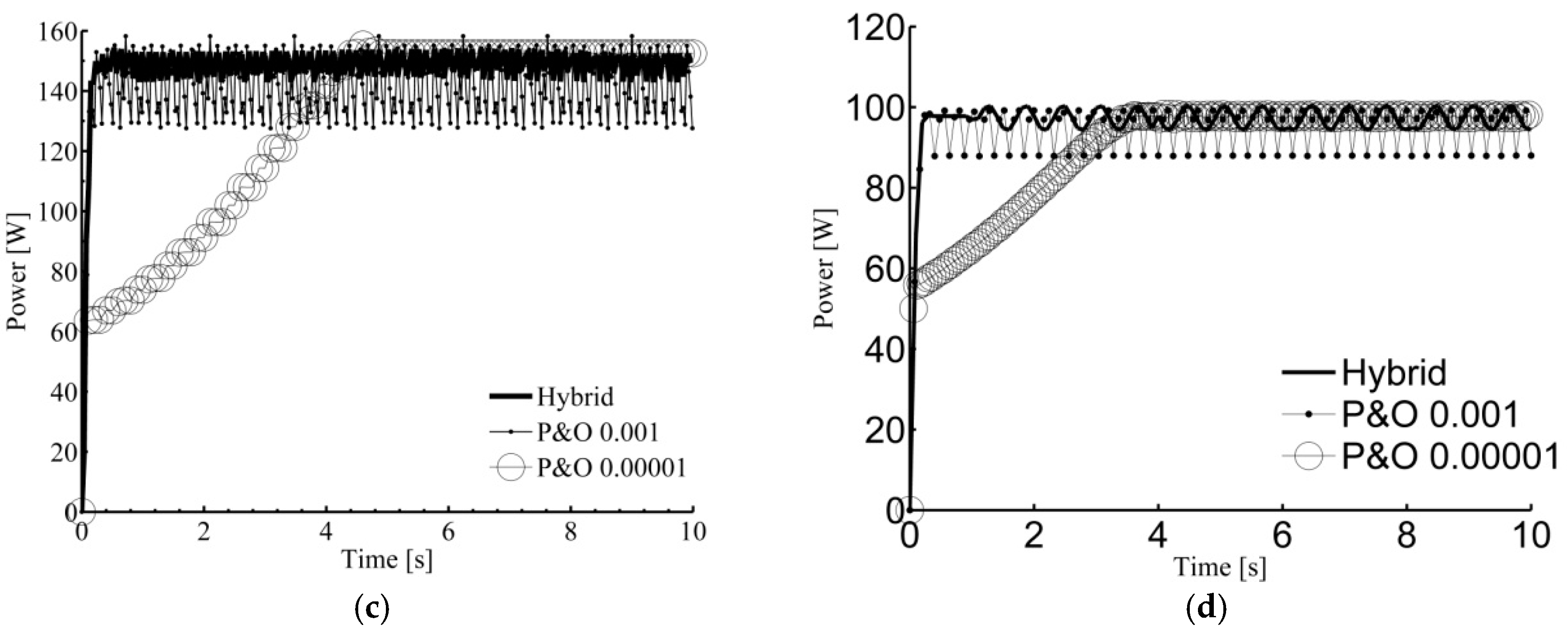
Figure 9.
Simulation results under partial shading conditions, (a) (1000, 300) W/m2; (b) (800, 300) W/m2; (c) (500, 200) W/m2; (d) (400, 100) W/m2.
Figure 9.
Simulation results under partial shading conditions, (a) (1000, 300) W/m2; (b) (800, 300) W/m2; (c) (500, 200) W/m2; (d) (400, 100) W/m2.


Figure 10.
Simulation results under sudden changes in radiation levels. (a) Dropping from 1000 to 300 W/m2; (b) Dropping from 900 to 400 W/m2; (c) rising from 250 to 850 W/m2; (d) rising from 300 to 700 W/m2.
Figure 10.
Simulation results under sudden changes in radiation levels. (a) Dropping from 1000 to 300 W/m2; (b) Dropping from 900 to 400 W/m2; (c) rising from 250 to 850 W/m2; (d) rising from 300 to 700 W/m2.

Figure 11.
Simulation results under partial shading conditions of 985–317 W/m2, (a) performance of; (b) P–V characteristics of STP270 PV module with the power levels obtained by the three controllers.
Figure 11.
Simulation results under partial shading conditions of 985–317 W/m2, (a) performance of; (b) P–V characteristics of STP270 PV module with the power levels obtained by the three controllers.


Table 1.
Electrical specifications the STP 270-24/Vd PV module [49].
Table 1.
Electrical specifications the STP 270-24/Vd PV module [49].
| Electrical Characteristic | STP270-24/Vd |
|---|---|
| Optimum Operating Voltage (Vmp) | 35.0 V |
| Optimum Operating Current (Imp) | 7.71 A |
| Open-Circuit Voltage (Voc) | 44.5 V |
| Short-Circuit Current (Isc) | 8.20 A |
| Maximum Power at STC (Pmax) | 270 W |
| Temperature Coefficient of Voc | −0.34%/°C |
| Temperature Coefficient of Isc | 0.045%/°C |
Table 2.
ANFIS-Editor training parameters.
| Fuzzy Logic Type | Sugeno |
|---|---|
| Number of inputs | 2 |
| Number of membership function | 10 |
| No of TRAINING a epochs | 3000 |
| Input membership function type | Gaussian |
| output membership function type | Linear |
| Algorithm used | Grid partitioning |
| Optimization method | Hybrid |
Table 3.
Performance of fuzzy controller under partial shading conditions at points not utilized in training.
Table 3.
Performance of fuzzy controller under partial shading conditions at points not utilized in training.
| Case No. | Weather Condition | Ir1 (Watt/m2) | Ir2 (Watt/m2) | Nominal Power (Watt) | Power after Fuzzy (Watt) | Efficiency |
|---|---|---|---|---|---|---|
| 1 | Uniform Irradiation | 1000 | 1000 | 258 | 258 | 100% |
| 2 | 900 | 900 | 232 | 232 | 100% | |
| 3 | 800 | 800 | 207 | 206 | 99.6% | |
| 4 | 700 | 700 | 181 | 179.1 | 99% | |
| 5 | 600 | 600 | 155 | 154.2 | 99.5% | |
| 6 | 500 | 500 | 128.5 | 127.6 | 99.3% | |
| 7 | 400 | 400 | 103.2 | 102.6 | 99.6% | |
| 8 | 740 | 740 | 190.3 | 163.4 | 85.7 | |
| 9 | 585 | 585 | 150.63 | 139.2 | 92.4 | |
| 10 | 597 | 597 | 153.8 | 151.6 | 98.5 | |
| 11 | Partial Shading | 1000 | 300 | 128.1 | 122.5 | 96% |
| 12 | 800 | 300 | 101.4 | 99.3 | 98% | |
| 13 | 500 | 200 | 58.1 | 56.2 | 96.7% | |
| 14 | 400 | 100 | 46.3 | 44.8 | 96.5% | |
| 15 | 700 | 300 | 48.7 | 47.5 | 99% | |
| 16 | 892 | 407 | 126.3 | 106.8 | 84.4% | |
| 17 | 644 | 596 | 103.7 | 92.3 | 89.0% | |
| 18 | 400 | 100 | 46.3 | 38 | 82.1% |
Table 4.
Comparison between P&O with different step sizes, fuzzy and the proposed hybrid controllers.
Table 4.
Comparison between P&O with different step sizes, fuzzy and the proposed hybrid controllers.
| Controller | Accuracy | Convergence | Oscillations | Trapping |
|---|---|---|---|---|
| Fuzzy | Moderate | Fast | Low | No |
| P&O/large step size | Low | Fast | High | Yes |
| P&O/small step size | High | Slow | Moderate | Yes |
| Hybrid | High | Fast | Moderate | No |
Table 5.
Performance of hybrid algorithm under partial shading conditions at points not utilized in training.
Table 5.
Performance of hybrid algorithm under partial shading conditions at points not utilized in training.
| Case No. | Ir1 (Watt/m2) | Ir2 (Watt/m2) | Nominal Power (Watt) | FLC Alone (Watt) | Hybrid Proposed Algorithm (Watt) |
|---|---|---|---|---|---|
| 1 | 1000 | 300 | 128.1 | 122.5 | 127.9 |
| 2 | 800 | 300 | 101.4 | 99.3 | 101.2 |
| 3 | 500 | 200 | 58.1 | 56.2 | 57.9 |
| 4 | 400 | 100 | 46.3 | 44.8 | 46.2 |
| 5 | 700 | 300 | 48.7 | 47.5 | 48.5 |
| 6 | 892 | 407 | 126.3 | 106.8 | 126.2 |
| 7 | 644 | 596 | 103.7 | 92.3 | 103.5 |
| 8 | 400 | 100 | 46.3 | 38 | 46.1 |
© 2018 by the authors. Licensee MDPI, Basel, Switzerland. This article is an open access article distributed under the terms and conditions of the Creative Commons Attribution (CC BY) license (http://creativecommons.org/licenses/by/4.0/).
Share and Cite
MDPI and ACS Style
Bataineh, K.; Eid, N. A Hybrid Maximum Power Point Tracking Method for Photovoltaic Systems for Dynamic Weather Conditions. Resources 2018, 7, 68. https://doi.org/10.3390/resources7040068
AMA Style
Bataineh K, Eid N. A Hybrid Maximum Power Point Tracking Method for Photovoltaic Systems for Dynamic Weather Conditions. Resources. 2018; 7(4):68. https://doi.org/10.3390/resources7040068
Chicago/Turabian StyleBataineh, Khaled, and Naser Eid. 2018. "A Hybrid Maximum Power Point Tracking Method for Photovoltaic Systems for Dynamic Weather Conditions" Resources 7, no. 4: 68. https://doi.org/10.3390/resources7040068
Note that from the first issue of 2016, this journal uses article numbers instead of page numbers. See further details here.