Systems Engineering Approach to Slope Stability Monitoring in the Digital Mine


CSIRO Minerals, P.O. Box 883, Kenmore, Brisbane 4069, Australia
*
Author to whom correspondence should be addressed.
Resources 2020, 9(4), 42; https://doi.org/10.3390/resources9040042
Submission received: 26 February 2020
/
Revised: 31 March 2020
/
Accepted: 14 April 2020
/
Published: 15 April 2020
(This article belongs to the Special Issue Advances in Mining Technology: The Digital Mine)
Abstract
:Slope stability monitoring in open cut mining is increasingly based on the use of a variety of different sensors and associated analytics, each capable of providing part of the understanding required to manage complex geotechnical environments. Designing an integrated monitoring system that is both attainable and fit for purpose can therefore be particularly challenging. In this paper, a systems engineering approach based on a novel methodology is presented to design the slope monitoring system. The methodology uses the rock engineering systems (RES) approach to system decomposition for geotechnical engineering problems, to determine the critical rock mass behaviours requiring monitoring. It follows this with the application of the system theoretic process analysis (STPA) approach, to design the control system for the monitoring system and identify and mitigate sub-optimal configurations. We demonstrate that the approach is practical to implement and supports transparent and defensible decision making for designing and implementing slope monitor systems. We apply the method to the design of a monitoring system for an Australian coal mine and demonstrate how the approach can facilitate the identification and design of new sensing modalities.
1. Introduction
The digital mining age has arrived and offers the ability to build more integrated sensing and monitoring networks, including the introduction of new sensing modalities, to support rock mass engineering, both in design and operational settings. Slope and ground control monitoring systems are a critical part of current and new mining methods. As the maturity of digital mining technology increases, these systems will increasingly contain multitudes of new sensors, potentially integrated through third party providers of integration platforms. The surface and sub-surface sensors and monitors include;
- Terrestrial and satellite-based radar (both synthetic and real aperture)
- Photogrammetric scanning
- Laser scanning
- Piezometric monitoring
- Borehole geophysics (seismic, microseismic, electromagnetic…)
- Surface geophysics (seismic, microseismic, electromagnetic…)
- Aerial geophysics (electromagnetic, gravity…)
However, the sophistication of these current and emerging sensing technologies does not mitigate the complexity of the underlying rock mass being monitored and, indeed, the complexity of the integrated monitoring system itself. Case studies of heavily monitored slopes that have behaved unpredictably abound, including Manefay failure [1], which occurred during the use of multiple ground based radar monitors, robotic prism monitoring and other monitors; the Turkey mine disaster [2] which occurred during the use of a sub-optimally placed ground based radar monitoring station; and multitudes of smaller scale failures which have impacted production. Indeed, the need for a firm understanding of rock mass behaviour independent to the monitoring was well documented by founders of the slope monitoring radar systems [3].
Further, well designed monitoring systems will increasingly lend themselves towards more strategic use (as opposed to the current situation, where they are predominantly used tactically). This will support processes such as the calibration of geomechanical and operational modelling, and the real-time updating of mining simulations for forecasting. Therefore, the use of a formal systems engineering approach is required to support the design of slope monitoring systems for the digital mine.
According to the Guidelines for Open Pit Slope Design [4], installation of a geotechnical monitoring system should be conducted in the context of answering particular geotechnical questions. They recommend the following steps:
- define project conditions;
- predict all potential mechanisms that could control instability;
- determine parameters to be monitored and potential magnitudes;
- establish suitable monitoring systems, including instrumentation and location;
- formulate measurement procedures (data sampling, processing, interpretation and reporting);
- assign tasks for design, construction, and operation of systems;
- plan regular calibration and maintenance; and
- establish trigger action response plans (TARPs) and associated accountabilities
However, in [4], it is also observed that instruments are often placed without this focus and therefore both the efficiency and effectiveness of the monitoring program are compromised. Part of the reason for this problem is that there is little guidance in the literature for completing steps a to d shown above, and therefore there is great reliance on the expertise of the practitioner. If a formal methodology could be derived, it would have the potential to provide practitioners with the tools to design and implement slope monitoring systems that concur with the recommendations above.
In this paper, we present a novel methodology to provide a systems engineering based structured approach to addressing these needs. The approach also mitigates the problems with implementing optimal monitoring systems, given the aforementioned complexities. The methodology uses the rock engineering systems (RES) approach to system decomposition for geotechnical engineering problems and the system theoretic process analysis (STPA) approach for identifying and mitigating sub-optimal configurations in complex systems. Through the application of these techniques, we demonstrate how monitoring requirements for a complex rock mass can be derived and how design of the slope monitoring system can be achieved. Note that although surface mining is the subject of this paper, the same techniques can be applied to underground mining for the design of ground control monitoring systems.
2. Materials and Methods
2.1. Rock Engineering Systems
The formulation of the “geotechnical questions” to be answered with the assistance of the monitoring system (Guidelines for Open Pit Slope Design [4]) requires a structured approach. The engineering of rock mass necessarily involves an analysis of the (potentially complex) interplay between the dominant rock mass components relevant to the design, implementation and maintenance of the excavation. Traditionally, this has been the domain of the geotechnical engineering department and involves relevant subject matter experts and supporting experience in similar rock mass conditions. More recently, the use of computational techniques, such as numerical simulation, has supported the interrogation of these relationships. With the advent of highly monitored rock mass systems and more sophisticated simulation, the opportunity to gather large databases capturing rock mass behaviour in dynamic and transient conditions, and the application of data mining and machine learning techniques, will be the next step.
The proposed structured approach to determine these principal rock mass engineering components required for consideration in the monitoring system is the rock engineering systems or RES [5,6]. The principal benefit of RES is its analytic approach that involves studying the rock mass engineering system, breaking the problem down into its constituent variables, and assessing their significance and relative importance, so that an appropriate model can then be constructed. Although this paper is the first-time application of RES for the derivation of slope monitoring requirements, Hudson [6] describes how the approach has been used for other applications in both mining and civil engineering. Use cases include analysis of surface and underground blasting [7,8], natural and engineered slope stability [9,10], tunnel boring machine performance [11], underground nuclear waste repositories [12] and ground control [13,14]. It has also been applied in other domains, including analysis of power station location and traffic induced pollution.
Fundamental to the RES approach is the construction of an interaction matrix [5], to consider the interactions between the main parameters relevant to the analysis. It is directly analogous to a network diagram as used in network theory and therefore supports computational implementations. The approach is flexible in that it can accommodate quantitative or qualitative parameters, which is of importance to geotechnical engineering, where often qualitative judgements are available. The parameters are listed in the diagonal of the matrix and are termed the leading diagonal terms. The off-diagonal entries indicate the type and degree of interaction between the parameters.
For example, consider the following simple 2 × 2 matrix, shown in Figure 1. This simple example conveys the interaction between the parameters ‘rock mass properties’ and ‘slope stability’. For example, the rock mass defects may form the controls for a potential slope instability (hence the off-axis cell description “Influence of rock mass properties on slope stability”). As mining progresses, this instability eventuates and the resulting slope deformation results in further rock mass damage (hence the off-axis cell description “Influence of changing slope stability on rock mass properties”). Note that the matrix can either be symmetric (i.e., interactions between parameter pairs are not sensitive to which parameter is labelled as the cause), or asymmetric. Note also that a clockwise influence convention is used (that is, given two parameters on the diagonal, the direction of influence is read clockwise, starting at the parameter which is higher on the diagonal).
Once this matrix is constructed, it can then be ‘coded’, such that the off-diagonal cells convey the importance of interactions (in terms of their causal and effect relationship to others) and support the mathematical manipulation of the matrix. There are five main methods to accomplish this coding:
- Binary: the mechanisms in the off-diagonal boxes are either switched on or off, so the coding is either as 1 or 0;
- Expert semi-quantitative (ESQ): a number from 0 to 4 is allocated as follows: 0–No interaction; 1–Weak interaction; 2–Medium interaction; 3–Strong interaction; 4–Critical interaction;
- According to the slope of an assumed linear relation;
- More numerically via a partial differential relation;
- Explicitly via the complete numerical analysis of the mechanism.
The method utilised in this paper is Method 2 (ESQ), based on subject matter expert elicitation, since the others are either too insensitive or require information that are rarely available. Note that with the advent of computational statistics and artificial intelligence approaches such as neural networks, Methods 4 and 5 may also become practical alternatives to expert elicitation in the future but would require enough historical data of mining operations for network training purposes.
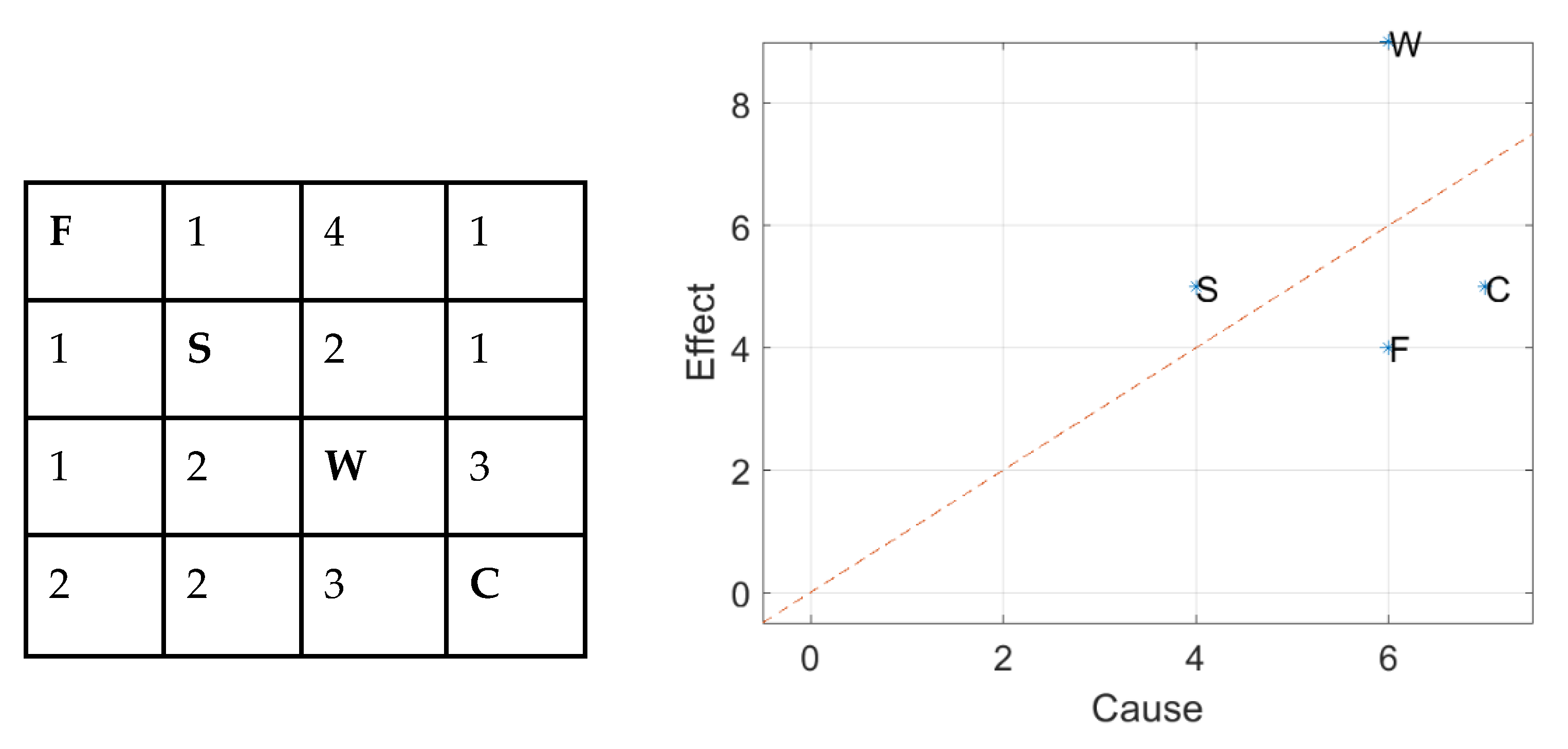
Once the off-diagonal terms have been coded, the values in a row can be summed to indicate a C (cause) ordinate for a particular variable, and likewise for those in the column to give the associated E (effect) ordinate. The ‘intensity’ of the interaction is then derived by summing C and E for each variable. Further, parameter dominance can also be established by determining the difference C–E. Both these metrics are shown in a cause-effect plot (Figure 2). If all parameters lie on the C–E line, then only their relative interaction intensity need be considered. Four parameters are considered in this example, namely fracture intensity (F), rock stress (S), water (W) and construction (C). For parameters that lie off-axis, both their intensity and dominance need to be considered. In this example, water has both high intensity and (effect) dominance.
Once this dominance is established, high level requirements for the monitoring system (such as sensor type and characteristics, analysis and reporting) can be established based on the parameter dominance.
2.2. System-Theoretic Process Analysis
The design of the monitoring system involves the integration of multiple sensors and analytics. The use of the control theory to understand the behaviour of this system supports the identification of optimal system design, as well as the mitigation of potentially undesirable system behaviour which can lead to the misinterpretation of geotechnical behaviour of the slope. STPA (system-theoretic process analysis) is a control theory-based hazard analysis technique that uses an extended model of accident causation. In addition to system component failures, STPA assumes that accidents can also be caused by unsafe interactions of system components, none of which may have failed [15].
The standard approach of handling complexity relies on breaking the system into smaller components, examining and analysing each component separately, and then combining the results in order to understand the behaviour of the assembly of components. The success of this type of reductionist approach relies on the assumption that the separation and individual analysis do not distort the phenomenon or property of interest. Furthermore, the traditional ‘root-cause’ analysis may give the illusion that more control of the system is present, as it ignores systemic issues which could present in the future as other ‘root-causes’.
Systems theory takes a different approach and looks at emergent properties of the system by studying component relationships and interactions. There are several advantages of this approach over traditional methods and it can detect more causal scenarios than traditional hazard analysis methods. Table 1 summarises the main differences in these methods.
A detailed comparison of STPA with the more widely used failure mode and effect analysis (FMEA) can be found in [16], which identifies a clear benefit of STPA; its ability to identify causal factors for identified unsafe control actions and hazards. This approach, therefore, is ideal for the analysis of complex control systems, such as a slope stability monitoring system, involving sensing, analytics and human “actors”. Hence, in this paper, we propose its application for the first time in geotechnical engineering. Examples of the successful application of STPA for analysis in other engineering applications can be found for missile defense systems [17], space craft design [18] and the design of airspace control systems [19].
A formal STPA process model defines the integrated slope monitoring (SM) system as a control system, where unsafe actions between system components that may cause a loss will be identified and mitigated. Once unsafe actions and their causes have been identified, controls can be implemented to eliminate or mitigate the unsafe control actions. In the following section, we describe how the STPA process could be applied at any operating mine.
This is achieved through an iterative four step process using the STPA method:
- Define the purpose of the analysis
- Define the control structure
- Identify unsafe control actions
- Identify loss scenarios
The control structure, which defines the adjacency and interactions between the various system components, and most importantly the feedback loops that must be present to verify component performance, must then be established. Once this is done, unsafe control actions can be identified, and loss scenarios defined. Finally, this supports the re-design of the system to mitigate these loss scenarios.
Once the loss scenarios have been identified, relevant controls shall be recommended or implemented to prevent the loss.
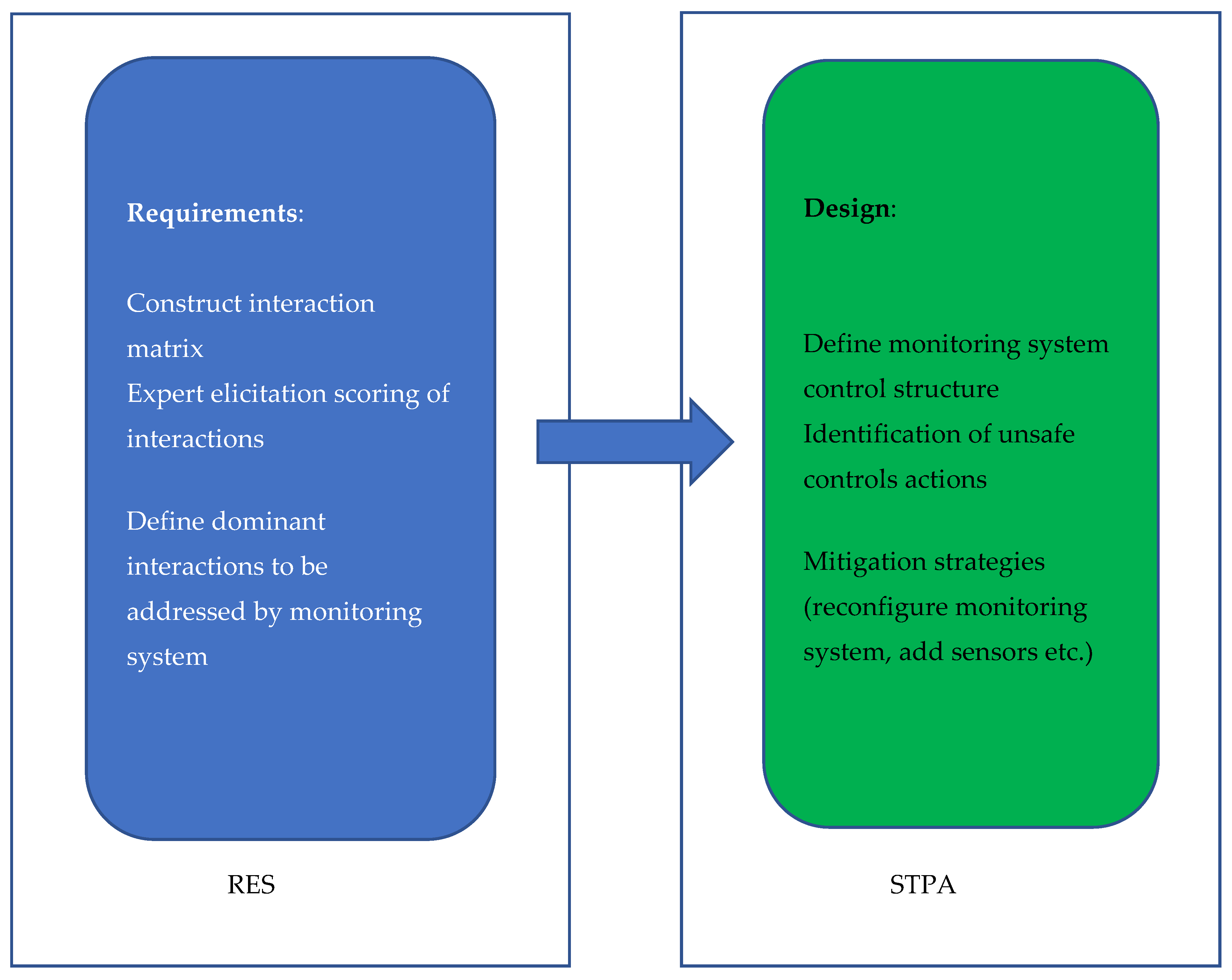
2.3. The Proposed Approach—RES and STPA for Slope Monitor Design
A summary of the proposed methodology for monitoring system design is shown in Figure 3. RES is used to decompose the rock engineering problem into its principal components, which drive the high-level requirements for the monitoring system. These requirements are then used as the basis of the monitoring system design, which is assessed and refined through STPA. This systematic and structured approach provides transparency and defensibility in the decision-making process associated with framing the geotechnical questions needing to be answered by the slope monitoring system, as well as the implementation of the slope monitor system.
3. Results
3.1. Derivation of Slope Monitor Requirements for a Coal Mine Highwall
We have applied the method to the design of a monitoring system for an unnamed operating open pit coal mine in one of the major coal basins on the eastern coast of Australia. The Eastern slope consists of 50 m highwalls (hereafter the ‘East wall’), with coal seams ranging from centimetres to metres in thickness. Coarse to fine-grained sediments host the beds which include the coal measures that are mined, and sediments may unconformably overlie basement rocks. The geological structure of the coal measures may comprise N–S trending normal faults, with faults and shear zones showing significant strike-slip displacement. The relative thickness, frequency of occurrence, and contrast of competence among strata vary with location, adding further complexity to the geotechnical conditions.
Structurally controlled wall stability may be influenced by curviplanar fractures with continuity and persistence of tens of metres in the interburden. Such defects may not be detectable from exploration drilling. Jointing is typically into two orthogonal steeply dipping sets.
Figure 4 presents a single radar monitoring system as used at the mine for either highwall or low wall surveillance. The radar can pan azimuthally to allow monitoring of walls with significant strike distance. The radar’s sensitivity is limited to line-of-sight (LOS) deformation, which limits the effectiveness of this approach, particularly when monitoring obliquely. The use of multiple radar systems to monitor a single wall is rare at this and other coal mine sites, due to the prohibitive costs associated with such systems.
Table 2 shows the RES analysis that was conducted specifically for the East wall being monitored at the mine, considering the interactions of the four geotechnical model components (as defined in Guidelines for Open Pit Slope Design [4]) and the mine slope stability. Actual site conditions and the historical performance of mining activities (e.g., blasting) were taken into account, based on the advice from geotechnical engineers at the mine and geotechnical consultant reports. Details are included in the table, but of note is the presence of low frequency structure sets, with high variability in both orientation and persistence.
The interaction matrix was then coded using the aforementioned semi-quantitative method as described in [5], with the results presented in Figure 5. The coding exercise attempts to quantify the degree of interaction between the components, within the context of slope stability. If numerical analysis is available, this can assist the coding, however it is rarely the case that sensitivity analyses across all relevant components have been performed. Therefore, in an operational setting, such coding sessions should take place with relevant subject matter experts who have prior knowledge of the rock mass conditions. These sessions should involve structural geologists, hydrogeologists and geotechnical engineers. Convergence on the scoring takes place in the context of discussing the particular geotechnical conditions relevant to the site being monitored.
Based on this RES, the critical rock mass behaviours requiring characterisation and monitoring were identified. In particular, the high interactive intensity of the structure parameter and the causal dominance of the rock mass and geology components were identified, likely leading to composite failures in the slope. From a monitoring perspective, hydro-geology conditions have also been identified as having both moderate interactive intensity. Therefore, the characterization of all four geotechnical model components are relevant for the East wall. This RES analysis has therefore provided a justification for establishing the monitoring system requirements (as required by Guidelines for Open Pit Slope Design [4]). The following high-level monitoring requirements have been defined:
- R1:
- Adequate monitoring of the pore pressures and phreatic surface well behind the highwall
- R2:
- Geotechnical characterisation of the geological structures in the domain of interest and relationship to excavation geometry, and in particular interaction of minor structures with major faults
- R3:
- Strength estimation of both rock matrix and discontinuities, particularly in altered and weathered regions and regions susceptible to composite failure
- R4:
- Deformation monitoring across both geological and geotechnical domains above and proximal to mining operations adequate for failure mechanism identification
3.2. Design of the Slope Monitor based on Derived Requirements
The results of the RES analysis and derived requirements R1–R4 were then used to develop the integrated slope monitoring (SM) system. It is important to note that this analysis has been performed specifically for the geotechnical conditions of the East wall. Performing the analysis for a different wall or site would likely lead to a different interaction matrix and certainly lead to different coding results. Following the methodology described in Section 2.2, the STPA analysis purpose was defined to be the design of the SM. The geotechnical engineering department is responsible for slope monitoring, which could cause downstream losses that impact the mining operations if the slope stability assessment is not fit for purpose (i.e., inaccurate, imprecise). This analysis was bound by the slope monitoring system itself (i.e., excluding other processes such as mining process considerations). Its purpose was to improve the reliability and robustness of the slope stability assessment process by placing controls to prevent scenarios that could potentially result in one or more of these losses relevant to the SM design (L):
- L-1: Loss of life or injury to people
- L-2: Loss of profitability of mining operation
- L-3: Loss of or damage to equipment
- L-4: Reputational damage
The system hazards (‘H’) are traceable to a loss, where a hazard is a system level state that may lead to one or more of the loss scenarios. The system constraints (‘SC’) were also identified that define the system conditions that need to be satisfied to prevent a hazard. For the proposed slope monitoring system, these are traceable to both a hazard and one or more losses as follows:
- ●
- H-1: SM produces inaccurate (aggressive) estimation of slope stability state (L-1, L-3, L-4)
- ○
- SC-1: SM must not over-estimate slope stability state (H-1)
- ●
- H-2: SM produces inaccurate (conservative) estimation of slope stability state (L-2, L-4)
- ○
- SC-2: SM must not under-estimate slope stability state (H-2)
- ●
- H-3: SM produces imprecise estimation of slope stability state (L-1, L-2, L-3, L-4)
- ○
- SC-3: SM must report reliability of slope stability state (H-2)
The hierarchical control structure diagram, which shows the interactions between controllers and controlled processes that will form the system, was then defined as shown in Table 3. Controllers (may be human or machine) provide control actions to the controlled processes that provide feedback, to ensure that system constraints are enforced. Each controller is represented as a box and control actions (commands) as arrows flowing from a controller. Assumptions associated with the controller model can also be included. In this case, the geotechnical department has access to a third-party sensor integration platform, and slope stability analysis is outsourced to a geotechnical engineering consulting company.
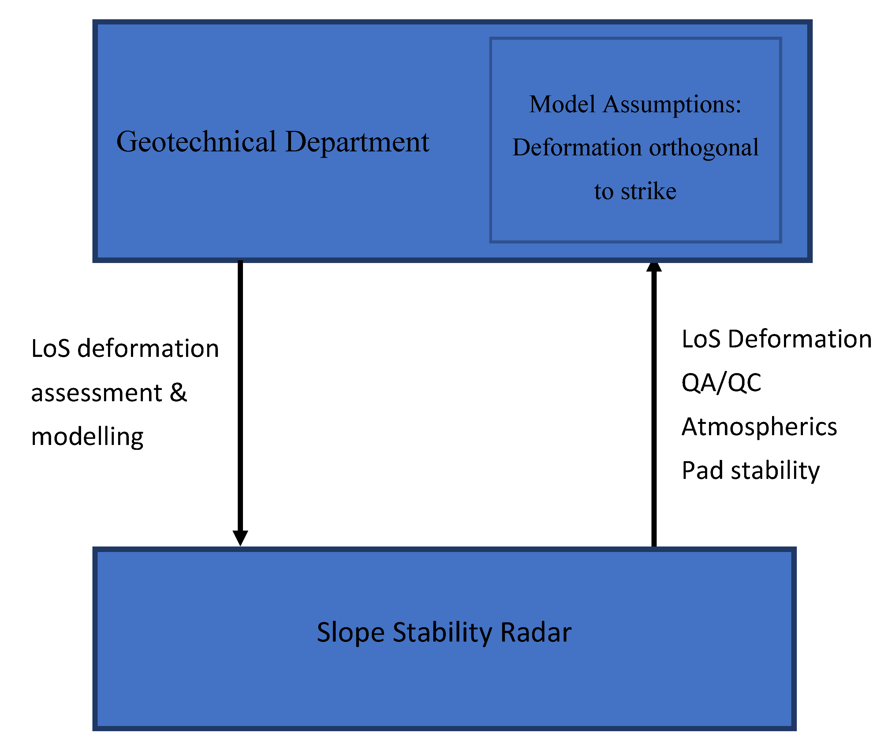
The slope monitor control structure was derived from the RES analysis where the geotechnical department sits at the top of the hierarchy (it controls the slope stability assessment). The high-level conceptual control structure diagram is shown in Figure 6 and the surface deformation component is shown to be bound by a dashed box. To constrain the rest of the analysis in this paper, the surface deformation component was extracted into a separate control diagram shown in Figure 7.
Figure 7 shows the first iteration of a control structure analysis for the surface deformation monitoring sub-component shown in Figure 6. The slope stability radar provides line of sight deformation data and quality assurance and control data (including data on atmospherics and pad stability) to the geotechnical department. Based on this data, deformation assessment and modelling are undertaken, and this influences how the geotechnical department continues to deploy the radar (i.e., positioning and frequency of monitoring). Note that the SM requirement R4 is not met if the model assumptions are invalid. In this example, the “deformation orthogonal to strike” assumption is in question. The implications of this analysis are discussed in the following section.
4. Discussion
Both the RES and STPA methodologies benefit from the use of formal expert elicitation sessions with appropriate subject matter experts. This is a well recognised requirement for geotechnical engineering in general and supports mitigation of biases in expert judgement [20].
One of the principal benefits of using the STPA method is its ability to analyse the control system to identify potential unsafe control actions (UCAs). Such actions may occur due to one of these conditions:
- Not providing causes a hazard
- Providing causes a hazard
- Signal timing (too early, too late, out of order) causes a hazard
- Stopped too soon, applied too long causes a hazard
To demonstrate this approach, an assessment for just a single part of the control structure diagram is shown in Table 4. Each of these conditions is analysed.
Let us consider GE-UCA02 (deformation along direction of movement not detected) in more detail. This UCA is potentially unsafe because the radar only performs line-of-sight (LOS) deformation measurements. The RES analysis undertaken by the geotechnical department has raised the possibility that failure mechanisms may not concur with the assumption that the deformation will occur down dip (SM Requirement R4). If this assumption is not met, hazards (H1, H2 or H3) could occur, resulting in a loss scenario. The UCAs may then be used to identify the causal factors that can lead to a loss, by determining the reason why an UCA would occur. The analysis considers what could cause the controller to provide that UCA which could include mechanical failure, power failure, human error, flawed assumptions, software bugs, incorrect internal state, etc.
Again, let us consider GE-UCA02
- GE-UCA02: Deformation along direction of movement not detected (H-1, H-2, H-3)
- Scenario 1 for GE-UCA02: The correct deformation is not detected, due to the line-of-sight bias of the radar, that relies on it being positioned correctly
The analysis described above can assist in identifying current sensing modality limitations and in designing alternatives. This example has highlighted the need for true 3D deformation monitoring for an appropriate assessment of the slope stability state. The utilisation of a limited number of slope monitoring radars for an extensive strike distance has highlighted the sensitivity to LOS bias. This is the phenomenon where a sensor sensitive only to line of sight deformation (such as a slope monitoring radar) is blind to the non-LOS component of the deformation. This can be a significant contributor to misinterpretation of underlying failure mechanisms, and under-estimation of failure consequence (e.g., failed volume and runout). The use of a prism based monitoring system, or alternatively, a fused sensor modality, as shown in Figure 8, can address the LOS issue, by providing simultaneous observation of the perpendicular to line-of-sight (PLOS) component, thus supporting true 3D vector estimation.
The fused sensor modality identified from this analysis reduces the associated model assumptions identified in the original control structure and mitigates the limitations in that approach. To be sure, the fused sensor approach introduces new model assumption (and potentially feedback loops) that need to be analysed.
It is important to note that the proposed fusion of sensors derived via this analysis has been demonstrated to be technically feasible by the authors. As a result, the mine site has reviewed the proposed fused sensor approach and is currently supporting field trials of a prototype system.
5. Conclusions
A novel method, based on the use of RES and STPA, for the design of a reliable slope monitoring system, has been presented. The method allows for the optimal design of the monitoring system to account for particular rock mass conditions and mining methods and assists in the identification of potentially unsafe or sub-optimal operating modes of the system. The method also supports the design of new sensing modalities, such as the fused sensor approach described in this paper.
Through the structured approach outlined in this paper, transparency and defensibility of decision making for configuring slope monitor systems is supported. This can also assist in the financial decision-making associated with assessing acquisition options for expensive monitoring equipment within constrained budgets.
Notwithstanding the merits of the proposed approach, the following points should be addressed when implementing the proposed method:
- RES is a powerful methodology but requires appropriate subject matter experts to code the interaction matrix. In the authors’ experience, the expert elicitation sessions used to conduct this task should be formally organized and attendees given adequate time to familiarise themselves with the necessary materials in order to mitigate biases associated expert elicitation sessions.
- STPA is also a powerful method but similarly requires appropriate subject matter experts. The identification of unsafe control actions requires the careful and detailed consideration of the control system.
- The analysis methods described in this paper need to take into consideration the particular geotechnical conditions for the site being monitored. These conditions directly influence the derivation and coding of the RES interaction matrix, derivation of monitoring requirements and the subsequent monitor design and STPA control system analysis.
Other applications of the method are also possible, including underground mining and civil engineering operations.
Author Contributions
Conceptualization, M.E.; Methodology, M.E. and P.D.; Software, n/a.; Validation, M.E. and P.D.; Formal Analysis, M.E. and P.D.; Investigation, M.E.; Resources, n/a.; Data Curation, n/a.; Writing—Original Draft Preparation, M.E.; Writing—Review and Editing, M.E. and P.D.; Visualization, M.E.; Supervision, M.E.; Project Administration, M.E.; Funding Acquisition, M.E. All authors have read and agreed to the published version of the manuscript.
Funding
This research was internally funded by Commonwealth Scientific and Industry Research Organisation (CSIRO), Australia and externally funded by the Australian Coal Association Research Programme (ACARP).
Conflicts of Interest
The authors declare no conflict of interest.
References
- Panow, K.L.; Moore, J.R.; Hale, J.; Koper, K.D.; Kubacki, T.; Whidden, K.; McCarter, M. Massive landslide at Utah copper mine generates wealth of geophysical data. GSA Today 2014, 24, 4–9. [Google Scholar] [CrossRef] [Green Version]
- Farina, P.; Carla, T.; Intrieri, E.; Ketizmen, H.; Casagli, N. Characterization of a large slope failure in an open-pit mine through back analysis of satellite insar and ground based radar data. In Proceedings of the Slope Stability 2018, Seville, Spain, 10–13 April 2018. [Google Scholar]
- Cabrejo, A.; Harries, N. Effective Slope Monitoring for Open Cut Coal Mines; ACARP Press: Brisbane, Australia, 2012. [Google Scholar]
- Read, J.; Stacey, P. Guidelines for Open Pit Slope Design; CRC Press: Brisbane, Australia, 2009; ISBN 9780415874410. [Google Scholar]
- Hudson, J. Rock Engineering Systems: Theory and Practice; Ellis Horwood Ltd. Press: Chicester, UK, 1992; p. 185. ISBN 0137826249. [Google Scholar]
- Hudson, J. A review of Rock Engineering Systems applications over the last 20 years. In Rock Characterisation, Modelling and Engineering Design Methods; Taylor & Francis Group: London, UK, 2013; pp. 419–424. [Google Scholar]
- Latham, J.P.; Lu, P. Development of an assessment system for the blastability of rock masses. Int. J. Rock Mech. Min. Sci. 1999, 36, 41–55. [Google Scholar] [CrossRef]
- Faramarzi, F.; Farsangi, M.E.; Mansouri, H. An RES-based model for risk assessment and prediction of backbreak in bench blasting. Rock Mech. Rock Eng. 2013, 46, 877–887. [Google Scholar] [CrossRef]
- Rozos, D.B.G.; Skillodimou, H. Comparison of the implementation of rock engineering system and analytic hierarchy process methods, upon landslide susceptibility mapping, using GIS: A case study from the EasternAchaia County of Peloponnesus, Greece. Environ. Earth Sci. 2011, 63, 49–63. [Google Scholar] [CrossRef]
- Budetta, P.; Santo, A.; Vivenzio, F. Landslide hazard mapping along the coastline of the cilento region (Italy) by means of a GIS-based parameter rating approach. Geomorphology 2008, 94, 340–352. [Google Scholar] [CrossRef]
- Benardos, A.; Kaliampakos, D. A methodology for assessing geotechnical hazards for TBM tunneling—Illustrated by the athens metro, Greece. Int. J. Rock Mech. Min. Sci. 2004, 41, 987–999. [Google Scholar] [CrossRef]
- Agüero, A.; Pinedo, P.; Simón, I.; Cancio, D.; Moraleda, M.; Trueba, C.; Pérez-Sánchez, D. Application of the spanish methodological approach for biosphere assessment to a generic high-level waste disposal site. Sci. Total Environ. 2008, 403, 34–58. [Google Scholar] [CrossRef] [PubMed]
- Kim, M.K.; Yoo, Y.I.; Song, J.J. Methodology to quantify rock behavior around shallow tunnels by Rock engineering systems. Geosyst. Eng. 2008, 11, 37–42. [Google Scholar] [CrossRef]
- Yang, Y.; Zhang, Q. A hierarchical analysis for rock engineering using artificial neural networks. Rock Mech. Rock Eng. 1997, 30, 207–222. [Google Scholar] [CrossRef]
- Leveson, N.; Thomas, J. STPA Handbook. 2018. Available online: http://psas.scripts.mit.edu/home/get_file.php?name=STPA_handbook.pdf (accessed on 15 April 2020).
- Sulaman, S.; Beer, A.; Felderer, M.; Höst, M. Comparison of the FMEA and STPA safety analysis—A case study. Softw. Qual. J. 2019, 27, 349–387. [Google Scholar] [CrossRef] [Green Version]
- Pereira, S.; Lee, G.; Howard, J. A system-theoretic hazard analysis methodology for a non-advocate safety assessment of the ballistic missile defense system. In Proceedings of the AIAA Missile Sciences Conference, Monterey, CA, USA, 14–16 November 2006. [Google Scholar]
- Ishimatsu, T.; Leveson, N.; Thomas, J.; Fleming, C.; Katahira, M.; Miyamoto, Y.; Ujiie, R.; Nakao, H.; Hoshino, N. Hazard analysis of complex spacecraft using systems-theoretic process analysis. J. Spacecr. Rockets 2014, 51, 509–522. [Google Scholar] [CrossRef] [Green Version]
- Fleming, C.; Spencer, M.; Thomas, J.; Leveson, N.; Wilkinson, C. Safety assurance in NextGen and complex transportation systems. Saf. Sci. 2013, 55, 173–187. [Google Scholar] [CrossRef]
- Baecher, G.; Christian, J. Reliability and Statistics in Geotechnical Engineering; Wiley Press: Chichester, UK, 2003; ISBN 978-0-471-49833-9. [Google Scholar]
Figure 1.
An illustrative high-level 2 × 2 interaction matrix, showing the cause and effect relationship between rock mass properties and slope stability.
Figure 1.
An illustrative high-level 2 × 2 interaction matrix, showing the cause and effect relationship between rock mass properties and slope stability.

Figure 2.
The Rock Engineering Systems method to derive parameter interaction intensity and importance. The table (left) shows scored interaction for four parameters (fracture intensity (F), rock stress (S), water (W) and construction (C)) and the chart (right) shows the cause and effect scores for each. The dashed line indicates Cause = Effect.

Figure 3.
Integration of RES and STPA for the slope monitoring system design.

Figure 4.
Typical single radar-based monitoring system, as used at the coal mine on the East wall.

Figure 5.
Cause-effect analysis for geotechnical model components. Coded using the following key: 0 —No interaction; 1—Weak interaction; 2—Medium interaction; 3—Strong interaction; 4—Critical interaction. The table (left) shows scored interactions and the chart (right) shows the cause and effect scores. The dashed line indicates Cause = Effect.

Figure 6.
Control structure diagram for slope monitoring system with control actions and feedback arrows, shown and described in Table 3. Only the Surface deformation component is discussed in the remainder of this paper.
Figure 6.
Control structure diagram for slope monitoring system with control actions and feedback arrows, shown and described in Table 3. Only the Surface deformation component is discussed in the remainder of this paper.

Figure 7.
Control structure diagram for the surface deformation component.

Figure 8.
Control structure diagram for the fused sensor system.


Table 1.
Comparison of STPA and FMEA.
| FMEA | STPA |
|---|---|
| Based on reliability theory | Based on system theory |
| “Bottom-up” method (components defined) | “Top-down” method (system defined) |
| Component diagram used | Function control diagram used |
| Identification of component failure modes | Identification of unsafe control actions |
| Failure modes propagated upwards | Causal factors for unsafe state identified |
Table 2.
RES analysis for monitoring system. Grey cells indicate parameters being analysed.
| Geology | Well understood model constrains and controls the structural model. Weak strata associated with increased fracture intensity. | Complexity in geology (e.g., unconformities) leads to uncertainty in contact locations and orientations with consequent uncertainty in slope behaviour | ||
| Structure | Significant dependence of hydrogeological model on structural model (and its uncertainty) | Conjugate jointing well understood but low frequency sets highly variable in orientation and persistence for several geotechnical domains result in geotechnical complexity | ||
| Low strength jointing supports activation | Rock Mass | Wide range of rock mass strengths based on weathering and alteration. Composite failure mechanisms likely. | ||
| Joint strength reduced by pore pressures | Hydrology & Hydrogeology | Surface water flow affects mine design. Sub-surface flow associated with potential deep-seated failure mechanisms. | ||
| Blasting induced fracturing | Depressurisation activities, mining induced stress relief changes | Mining & Slope stability |
Table 3.
Controllers, actions and feedbacks in the slope stability monitor system.
| Controller | Process | Control Actions Supplied by Geotechnical Dept. | Feedback Provided to Geotechnical Dept. |
|---|---|---|---|
| Geotechnical Department | Estimate stability state of the slope (e.g., probability of failure) based on assessment/modelling of the states of input components | ||
| Hydro | Estimate surface and sub-surface water flows and pressures | HA: deployment and maintenance of pore pressure sensors | HF: pore pressure data; coverage and representativeness of network |
| Defect strength | Estimate strength parameters of defects | DA: sample extraction and laboratory analysis | DF: strength parameters; coverage and representativeness of sampling |
| Structure | Estimate geometry and rate of change of 3D structures | SA: borehole sampling and face mapping | SF: defect properties; coverage and representativeness of sampling |
| Rock mass | Estimate rock mass strength parameters | RA: sample extraction and laboratory analysis | RF: rock mass strength parameters; coverage and representativeness of sampling |
| Surface deformation | Estimate rates of 3D surface deformation | SDA: deployment and maintenance of slope deformation sensors | SDF: surface deformation data; coverage and sensitivity of network |
Table 4.
An entry in the Control action assessment.
| Controller | Control Action | Not Providing Cause Hazard | Providing Cause Hazard | Too Early, Too Late, Out of Order | Stopped Too Soon, Applied Too Long |
|---|---|---|---|---|---|
| GE (Geotechnical Engineer) | Detect Deformation | GE-UCA01: Deformation not detected during deployment (H-1, H-2, H-3) GE-UCA02: Deformation along direction of movement not detected (H-1, H-2, H-3) | NA | GE-UCA03: Deformation detected too late during deployment (H-1, H-2, H-3) | NA |
© 2020 by the authors. Licensee MDPI, Basel, Switzerland. This article is an open access article distributed under the terms and conditions of the Creative Commons Attribution (CC BY) license (http://creativecommons.org/licenses/by/4.0/).
Share and Cite
MDPI and ACS Style
Elmouttie, M.; Dean, P. Systems Engineering Approach to Slope Stability Monitoring in the Digital Mine. Resources 2020, 9, 42. https://doi.org/10.3390/resources9040042
AMA Style
Elmouttie M, Dean P. Systems Engineering Approach to Slope Stability Monitoring in the Digital Mine. Resources. 2020; 9(4):42. https://doi.org/10.3390/resources9040042
Chicago/Turabian StyleElmouttie, Marc, and Peter Dean. 2020. "Systems Engineering Approach to Slope Stability Monitoring in the Digital Mine" Resources 9, no. 4: 42. https://doi.org/10.3390/resources9040042
Note that from the first issue of 2016, this journal uses article numbers instead of page numbers. See further details here.