Article

A Three-Phase Resonant Boost Inverter Fed Brushless DC Motor Drive for Electric Vehicles

by
Prabhat Ranjan Tripathi
1,
Vijaya Laxmi
1,
Ritesh Kumar Keshri
2,
Amitkumar Vidyakant Jha
3,
Bhargav Appasani
3,
Nicu Bizon
4,5,* and
Phatiphat Thounthong
6
1
Department of Electrical and Electronics Engineering, Birla Institute of Technology, Mesra, Ranchi 835215, India
2
Department of Electrical Engineering, Visvesvaraya National Institute of Technology, Nagpur 440010, India
3
School of Electronics Engineering, Kalinga Institute of Industrial Technology, Bhubaneshwar 751024, India
4
Faculty of Electronics, Communication and Computers, University of Pitesti, 110040 Pitesti, Romania
5
Doctoral School, Polytechnic University of Bucharest, 313 Splaiul Independentei, 060042 Bucharest, Romania
6
Department of Teacher Training in Electrical Engineering, Faculty of Technical Education, King Mongkut’s University of Technology North Bangkok, 1518, Pracharat 1 Road, Bangsue, Bangkok 10800, Thailand
*
Author to whom correspondence should be addressed.
Electronics 2021, 10(15), 1799; https://doi.org/10.3390/electronics10151799
Submission received: 23 June 2021 / Revised: 25 July 2021 / Accepted: 26 July 2021 / Published: 27 July 2021

Abstract

:
The present article proposes a three-phase resonant boost inverter (TPRBI) to feed a permanent magnet brushless DC (PMBLDC) motor at the requested torque with low ripples due to the sinusoidal current injected into the PMBLDC motor. PMBLDC motors have the highest torque-to-weight ratio compared to other motors and are the best choice for electric vehicle applications. Conventionally, these motors are driven by voltage source inverters (VSI) with trapezoidal current injection, introducing unwanted torque ripples. Moreover, due to the buck operation of VSI, an extra power conversion stage is required to elevate the battery voltage level to desired DC-link voltage. This extra stage increases the number of components used, complexity of control and decreases the efficiency and reliability of the overall system. TPRBI injects sinusoidal current in the PMBLDC motor in the proposed method, thus minimizing the torque ripples. The proposed inverter also has an inherent voltage boost characteristic, thus eliminating the extra power conversion stage. The single-stage conversion from DC to boosted sinusoidal AC enhances the system reliability and efficiency and minimizes the cost and weight of the system. A MATLAB/Simulink model is presented along with simulation results and mathematical validation. A comparative evaluation of the proposed system with the conventional VSI-fed PMBLDC motor is presented in terms of induced torque ripples.

1. Introduction

Electric vehicles have emerged to be the most viable solution to reduce greenhouse gas (GHG) emissions at source. Currently, the transportation sector is heavily dependent on internal combustion engine (ICE) based vehicles, contributing to 16.2% of the global GHG emissions [1]. With advancements in power converter technologies, various electrical machines are now efficiently controlled and operated, forming an integral part of electric vehicles [2]. The reported literature suggests that although induction motors are industrial workhorses due to their high ruggedness, reliability, and simple construction and control when used in electric vehicle applications, they fail because of their low torque to weight ratio [3]. PMBLDC motors, on the other hand, use rare earth element magnets in the rotor, providing very high torque to weight ratio [4], thus making it the first choice for use in traction drives [5,6] using multiport converters [7,8].
A three-phase voltage source inverter conventionally feeds permanent magnet brushless DC (PMBLDC) motors with the help of synchronizing signals from hall effect sensors. Based on the Hall effect signals, the legs of the VSI are energized to rotate the motor at the desired speed. However, conventional VSI injects a trapezoidal current into the PMBLDC. Due to the trapezoidal current, the commutating and non-commutating currents are imbalanced, causing torque ripples on the shaft. Torque ripples are detrimental the electric vehicle stability and its dynamics. Therefore, many researchers have reported different current injections to reduce the torque ripples in the PMBLDC motor, such as sinusoidal current injection [9] and petal wave current injection [10].
The sinusoidal current injection minimizes the torque ripples, but generating a sinusoidal current from conventional VSI is a complex process and requires a lot of computational power and sensor arrangement. Moreover, the battery voltage required for the motor operation is higher than the individual cell voltage, and so it requires a combination with a large number of cells in series. However, with many cells in series, the reliability decreases and the complexity in the battery management increases [11]. Thus, the power converters with voltage boosting ability are investigated for electric vehicle applications [12]. The boost inverter proposed in [13] offers a solution for a single-phase application; however, it does not account for the three-phase application. The Z-source inverter (ZSI) proposed in [14] emerged as a new family of inverters capable of buck–boost operation for single-phase and three-phase applications by providing varying DC-Link voltage at an interim stage. Several modified topologies were reported based on ZSI [15,16,17], with a characteristic property of varying interim DC-link voltage. Numerous modulation strategies were investigated for these ZSIs and modified topologies [18], with their own merits such as zero voltage switching, maximum boost control, and maximum constant boost control.
In recent years, multilevel inverters (MLIs) capable of providing boosted AC voltage output for low voltage DC input have gained popularity. Various topologies such as flying capacitors and multi-H-Bridge cascading were investigated [19]. Multilevel inverters use single or multiple sources to provide many (depending on topology and switching) DC voltage levels at various switching times, giving a sinusoidal envelope of AC voltage at the output [20].
As Z-source inverters provide interim boosted DC-link voltage, switches are exposed to a higher blocking voltage. Higher blocking voltage across the switches results in a higher TBV of the converter topology [21,22,23]. Higher TBV signifies higher semiconductor costs and higher semiconductor loss. Multilevel inverters [24,25] and switched capacitor inverters [26] depend on high switching, and passive component counts for increasing the number of levels at the output side. It increases the cost and complexity of the system. Moreover, all the inverter topologies investigated employ high switching frequency at some or all stages of their operation. Higher switching frequency gives rise to higher switching loss, thereby increasing the heat-sink requirement of the converter.
This work proposes a three-phase boost inverter based on fundamental frequency switching capable of providing a high gain boost factor and sinusoidal current injection in the PMBLDC motor. The proposed TPRBI provides torque ripple minimization compared to the PMBLDC motor and eliminates an extra boost stage at the input side.
Thus, the novelty of this research study is as follows:
  • A new three-phase resonant impulse inverter (TPRBI) is proposed to drive a PMBLDC at high torque, but with low ripples due to the sinusoidal current injected into the PMBLDC motor;
  • The proposed inverter has an inherent voltage increase characteristic that leads to an increase in its efficiency by eliminating the extra boost power conversion stage, which is usually used by a voltage source inverter (VSI) feeding a PMBLDC;
  • The maximum torque per ampere is higher in the proposed TPRBI-fed PMBLDC motor than the conventional VSI-fed PMBLDC motor drive.
The paper is organized into five sections. Section 2 explains the circuit and working of TPRBI, Section 3 details the operation of PMBLDC with TPRBI and a comparison between square wave and sinusoidal current injection operation. Simulation results are shown in Section 4, followed by a conclusion in Section 5.

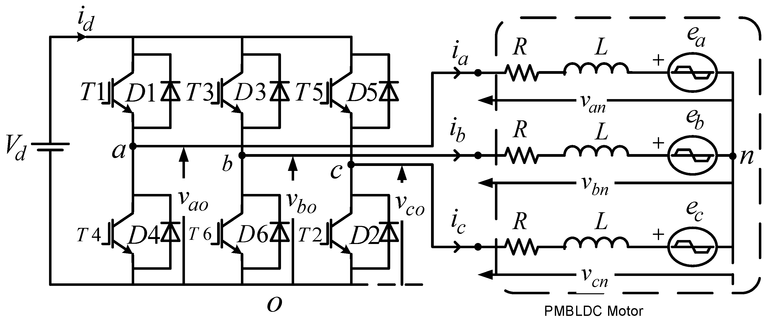
2. Three-Phase Resonant Boost Inverter: Circuit and Operation

The circuit diagram of the proposed TPRBI is shown in Figure 1. LC pairs (L—inductor and C—capacitor) are connected to the legs of a conventional three-leg three-phase VSI. The load is connected differentially to the mid-points of the LC pairs. VDC is the amplitude of the input DC voltage source.
All inductor and capacitor values are kept the same to ensure that the inverter is symmetric. As the input voltage source is parallel to all three legs, each leg can be attributed to the individual operation. The working of all the legs is the same and differs only in phase shift. The switching of the proposed inverter’s power semiconductor devices is performed at the fundamental frequency, and the duty cycle is changed from 0 to 0.5 as per load variation and required gain. The different switching states are explained in Table 1.
Each leg of the topology works in two modes, as illustrated in Table 1. These modes depend on the switching of the top or bottom switch. For dynamic modeling, each leg can be subdivided into two parts, i.e., synchronous switches for pulse generation and LC resonant pair for DC-biased sinusoidal wave generation, as shown in Figure 2. Where ST denotes top switch and SB bottom switch, Vpg denotes phase to DC ground voltage, and Req is equivalent resistance.
From Figure 2, for the synchronous switch part, the output equation can be written as:
V i n t = { D V d c ,                     t = D T s 0 ,                                     t D T s i n t
The second part of the circuit behaves as a single-ended two-pole filter. The transfer function for the circuit is given by:
G ( s ) = V p g ( s ) V i n t ( s ) = 1 1 + s L R e q + s 2 L C
The resonant frequency of the system (ωr) is
ω r = 1 L C
Rephrasing Equation (2) in a standard second-order form by substituting ωr from (3),
G ( s ) = V p g ( s ) V i n t ( s ) = ω r 2 s 2 + α s ω r + ω r 2
where α = 1 R L C .
Now by replacing s by in (4) results in:
G ( j ω ) = ω r 2 ( j ω ) 2 + α ( j ω ) ω r + ω r 2
The gain of the system is given by:
| G ( j ω ) | = 1 { 1 ( ω ω r ) 2 } 2 + α 2 ( ω ω r ) 2
At the resonant frequency, i.e., ω = ωr. Equation. (6) gives the value of gain to be 1/α, i.e.,
| G ( j ω ) | = 1 α = R C L
Now, for a pulse input, the response of an LC resonant circuit is a DC clamped sinusoid. Thus, the overall response of the system when switched at the resonant frequency is:
V P G = V D C + D R C L   V D C sin ( ω t )
where D is the duty cycle, and VDC is the input DC voltage.
Now, replacing R C L with G in (8),
V P G = V D C + D G V D C s i n ( ω t )
The three legs are phase-shifted by 120°, the dynamic equation for each leg is given by (10):
V A G = V D C + D G V D C s i n ( ω t ) V B G = V D C + D G V D C s i n ( ω t 120 ° ) V C G = V D C + D G V D C s i n ( ω t 240 ° )
The line-to-line voltage is:
V A B = 3 D G V D C s i n ( ω t + 30 ° ) V B C = 3 D G V D C s i n ( ω t 90 ° ) V C A = 3 D G V D C s i n ( ω t + 150 ° )
Equation (11) represents the overall equation of the converter, which shows that the proposed converter produces a three-phase voltage controlled by duty cycle variation.

3. PMBLDC Operation: Square vs. Sinusoidal Current Injection

The circuit diagram of a conventional VSI-fed trapezoidal back emf PM BLDC is represented in Figure 3. Where, v a o ,   v b o and v c o are the voltages from the motor stator terminal to the negative battery reference; v n o is voltage from the virtual neutral point to the negative battery reference; and i a , i b and i c are stator input currents. R and L is per phase stator resistance and inductance, respectively. Applying Kirchhoff’s voltage law (KVL), we obtain:
V P o = i P R + L d i P d t + e P + v n o
The index P represents phases, i.e., a, b, and c, for three phases. Multiplication with iP to both sides of (12) gives:
i P V P o = i P 2 R + L i P d i P d t + i P e P + i P v n o
By adding (13) for phases a, b, and c, we obtain:
P = a , b , c i P V P o = R P = a , b , c i P 2 + L P = a , b , c i P d i P d t + P = a , b , c i P e P + P = a , b , c i P v n o
PM BLDC motor has an isolated neutral point, so the sum of currents is constrained (15).
P = a , b , c i P = 0
The useful mechanical power obtained from the electrical power is given by (16).
p m = P = a , b , c i P e P
The mechanical power obtained at all times of operation from the instantaneous electrical power is obtained by substituting Equations (15) and (16) in Equation (14) and thus results in the overall Expression (17).
p m = τ m ω m = P = a , b , c v P o i P R P = a , b , c i P 2
Here, the motor shaft speed ( ω m ) and electromagnetic torque ( τ m ) have a relation as shown in Equation (18).
τ m = 1 ω m ( P = a , b , c v P o i P R P = a , b , c i P 2 )
Equation (18) provides information about the torque variation of a PMBLDC motor fed by a three-phase source irrespective of the current injection type. In the following subsections, the injected current waveforms for square and sinusoidal injection are calculated, and the analytical torque variation is shown.

3.1. Square-Wave Current Injection (Conventional Vsi)

When a conventional VSI feeds the PMBLDC, it injects a square wave current with an amplitude I. Then the sum of squares of current, i.e., P = a , b , c i P 2 , is given by Equation (19)
P = a , b , c i P 2 = 2 ( 1 i o u t i i n i n c 2 ) i n c 2
where iout, iin, and inc are shown in Figure 4 for a single commutation.
Commutating currents vary with the speed of the PMBLDC motor and have a variable value at each commutation cycle; thus, the value obtained from Equation (19) induces torque ripples at every commutating step when substituted in Equation (18). The variation of torque ripple in a PMBLDC motor when fed by a conventional VSI in an ideal and non-ideal setting is shown in Figure 5.

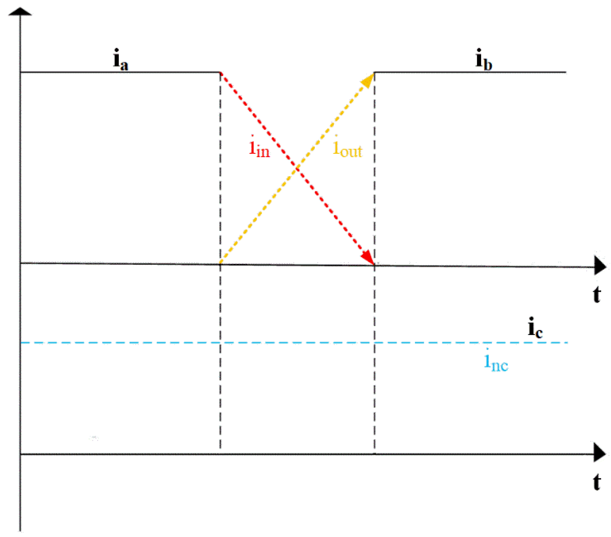
3.2. Sinusoidal Current Injection (Tprbi)
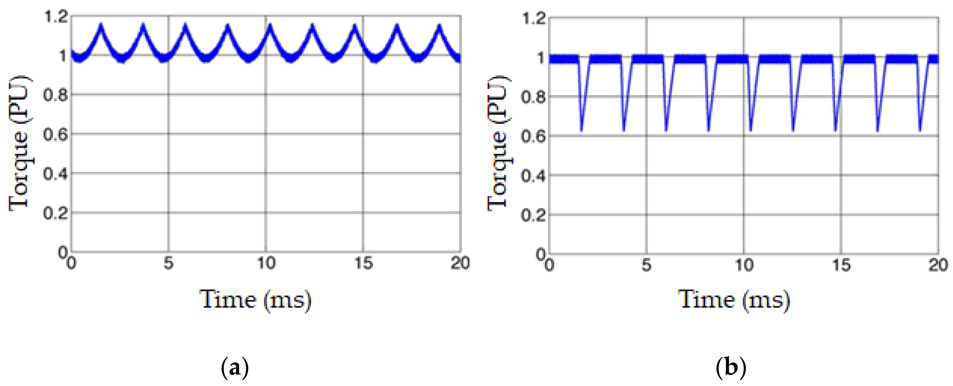
When a three-phase resonant boost inverter feeds the PMBLDC, it injects sinusoidal current into the stator. The peak value of the injected sinusoidal current is Ipeak.
Now for a balanced sinusoidal phase current injection, the sum of squares of current, i.e., P = a , b , c i P 2 is:
P = a , b , c i P 2 = [ s i n 2 θ + s i n 2 ( θ 2 π 3 ) + s i n 2 ( θ + 2 π 3 ) ] I p e a k 2 = 3 2 I p e a k 2
Substituting the Equation (20) in Equation (18), we obtain:
τ m = 1 ω m ( P = a , b , c v P o i P 3 2 R I p e a k 2 )
Now, Equation (21) denotes the torque ripple produced by the PMBLDC motor when fed by the proposed three-phase resonant boost inverter. As shown in the above equation, the second term is constant and does not vary with speed or commutation, as was the case when conventional VSI feeds PMBLDC. Thus, analytically, the PMBLDC fed by the proposed TPRBI has much lower torque ripples and has a smooth operation; moreover, due to fundamental frequency switching, zero current switching is obtained in TPRBI, thus minimizing the losses.

4. Results

The proposed system was simulated using the Simscape electrical toolbox in the MATLAB Simulink environment. The specification of the PMBLDC motor used for simulation is depicted in Table 2.
The circuit diagram of the PMBLDC drive fed by TPRBI is shown in Figure 6.
The simulation results for the injected phase current in TPRBI and VSI-fed PMBLDC motor are shown in Figure 7a,b, respectively.
It can be observed from Figure 7 that the amplitude of current injected, when fed with TPRBI, is close to the ideal sinusoid and leads to a torque ripple-free operation, while in the case of VSI-fed PMBLDC, the injected current has lots of harmonics resulting from commutations. The resulting torque produced by both TPRBI and VSI-fed PMBLDC motors is shown in Figure 8a,b, respectively.
It can be observed from Figure 8 that the torque ripples are minimized in the proposed TPRBI-fed PMBLDC drive; moreover, the maximum torque produced per ampere is higher in the case of the proposed system. A comparative evaluation of the proposed TPRBI-fed PMBLDC drive and conventional VSI-fed PMBLDC drive is presented in Table 3.
T B V = i = 0 n P I V ( i ) V o
where, n is the number of switches and VO is the output voltage. For VSI, the minimum PIV for each switch is VDC, and the maximum output is VDC, so the TBV is six because six switches are used. While for TPRBI, the max gain is 4, at that point PIV of switches is equal to VDC, but the output VO is four times VDC; thus, the TBV of the TPRBI is 1.5. The low value of the TBV signifies lower semiconductor cost and loss.

5. Conclusions

The present article reports a three-phase resonant boost inverter-fed permanent magnet brushless DC motor for electric vehicle applications. The working of the three-phase resonant boost inverter was mathematically represented and validated with simulation results. The generalized torque equations were obtained for a PMBLDC motor fed by a three-phase supply irrespective of the injected current waveforms. The analysis of the effects of square wave phase current injection and sinusoidal phase current injection on the torque of the PMBLDC motor was performed. The superiority of sinusoidal current injection over square wave current injection in terms of torque ripples was proved mathematically.
Further, for validation of the mathematical claims, a simulation model was developed. The simulation results also show that the maximum torque per ampere is higher in the proposed TPRBI-fed PMBLDC motor than the conventional VSI-fed PMBLDC motor drive. A lower value of total blocking voltage for the proposed system in comparison to the conventional system proves that the loss component of the TPRBI is lower than the VSI-fed PMBLDC drive. Thus the proposed system is beneficial and finds a practical application in electric vehicles for traction drives. As a next work, the experimental tests will be performed, and the experimental results will be compared with those obtained in the simulation to validate the proposed method.

Author Contributions

Conceptualization, P.R.T. and V.L.; methodology, P.R.T. and R.K.K.; software, P.R.T. and B.A.; validation, P.R.T. and A.V.J.; investigation, P.R.T.; resources, P.R.T. and B.A.; data curation, V.L. and R.K.K.; writing—original draft preparation, P.R.T., V.L. and R.K.K.; supervision: N.B.; project administration, P.T.; formal analysis, N.B.; funding acquisition, N.B. and P.T.; visualization, P.R.T. and A.V.J.; writing—review and editing: N.B., B.A. and P.T.; figure and table, P.R.T., V.L. and R.K.K. All authors have read and agreed to the published version of the manuscript.

Funding

This work was partially supported by the International Research Partnerships: Electrical Engineering Thai-French Research Center (EE-TFRC) between Université de Lorraine (UL) and King Mongkut’s University of Technology North Bangkok (KMUTNB), and Framework Agreement between the University of Pitesti and King Mongkut’s University of Technology North Bangkok through the Research Program Cooperation under Grant KMUTNB-FF-65-20.

Conflicts of Interest

The authors declare no conflict of interest.

References

  1. Ritchie, H.; Roser, M. Emissions by Sector—Our World in Data. Available online: https://ourworldindata.org/emissions-by-sector# (accessed on 2 June 2021).
  2. Shiue, Y.C.; Chen, P.J.; Lee, C.F.; Yu, C.C.; Chen, C.W. Foresight scenario analysis of motor system of electric vehicle. World Electr. Veh. J. 2012, 5, 975–981. [Google Scholar] [CrossRef] [Green Version]
  3. Phatiphat, P.; Sikkabu, S.; Poonnoy, N.; Mungporn, P.; Yodwong, B.; Kumam, P.; Bizon, N.; Nahid-Mobarakeh, B.; Pierfederici, P. Nonlinear Differential Flatness-Based Speed/Torque Control with State-Observers of Permanent Magnet Synchronous Motor Drives. IEEE Trans. Ind. Electron. 2018, 54, 2874–2884. [Google Scholar] [CrossRef]
  4. Keshri, R.K.; Tripathi, P.R. Torque estimator for a permanent magnet brushless DC motor drive. In International Transportation Electrification Conference (ITEC); Institute of Electrical and Electronics Engineers (IEEE): Piscataway, NJ, USA, 2015; pp. 1–5. [Google Scholar]
  5. Tuan, V.T.; Phattanasak, M.; Kreuawan, S. Integrated Charger-Inverter for High-Performance Electric Motorcycles. World Electr. Veh. J. 2021, 12, 19. [Google Scholar] [CrossRef]
  6. Zhao, X.; Tang, J. Modeling and optimal shift control of a planetary two-speed transmission. World Electr. Veh. J. 2019, 10, 53. [Google Scholar] [CrossRef] [Green Version]
  7. Bizon, N. Energy efficiency for the multiport power converters architectures of series and parallel hybrid power source type used in plug-in/V2G fuel cell vehicles. Appl. Energy 2013, 102, 726–734. [Google Scholar] [CrossRef]
  8. Bizon, N. Energy Efficiency of Multiport Power Converters used in Plug-In/V2G Fuel Cell Vehicles. Appl. Energy 2012, 96, 431–443. [Google Scholar] [CrossRef]
  9. Bertoluzzo, M.; Buja, G.; Keshri, R.K.; Menis, R. Sinusoidal Versus Square-Wave Current Supply of PM Brushless DC Drives: A Convenience Analysis. IEEE Trans. Ind. Electron. 2015, 62, 7339–7349. [Google Scholar] [CrossRef]
  10. Buja, G.; Bertoluzzo, M.; Keshri, R.K. Torque Ripple-Free Operation of PM BLDC Drives With Petal-Wave Current Supply. IEEE Trans. Ind. Electron. 2015, 62, 4034–4043. [Google Scholar] [CrossRef]
  11. Texas Instruments Battery Management Deep Dive on-Demand Technical Training. Available online: https://training.ti.com/introduction-battery-management (accessed on 1 June 2021).
  12. Tripathi, P.R.; Thakura, P.; Keshri, R.K.; Ghosh, S.; Guerrero, J.M. 25 Years of Single-Stage Buck-Boost Inverters: Development and Challenges. IEEE Ind. Electron. Mag. 2021. [Google Scholar] [CrossRef]
  13. Caceres, R.O.; Barbi, I. A boost DC-AC converter: Analysis, design, and experimentation. IEEE Trans. Power Electron. 1999, 14, 134–141. [Google Scholar] [CrossRef]
  14. Fang, Z.P. Z-source inverter. IEEE Trans. Ind. Appl. 2003, 39, 504–510. [Google Scholar] [CrossRef]
  15. Ellabban, O.; Abu-Rub, H. Z-Source Inverter: Topology Improvements Review. IEEE Ind. Electron. Mag. 2016, 10, 6–24. [Google Scholar] [CrossRef]
  16. Siwakoti, Y.P.; Peng, F.Z.; Blaabjerg, F.; Loh, P.C.; Town, G.E. Impedance-Source Networks for Electric Power Conversion Part I: A Topological Review. IEEE Trans. Power Electron. 2015, 30, 699–716. [Google Scholar] [CrossRef]
  17. Mande, D.; Trovão, J.P.; Ta, M.C. Comprehensive review on main topologies of impedance source inverter used in electric vehicle applications. World Electr. Veh. J. 2020, 11, 37. [Google Scholar] [CrossRef]
  18. Siwakoti, Y.P.; Peng, F.Z.; Blaabjerg, F.; Loh, P.C.; Town, G.E.; Yang, S. Impedance-Source Networks for Electric Power Conversion Part II: Review of Control and Modulation Techniques. IEEE Trans. Power Electron. 2015, 30, 1887–1906. [Google Scholar] [CrossRef]
  19. Vijeh, M.; Rezanejad, M.; Samadaei, E.; Bertilsson, K. A General Review of Multilevel Inverters Based on Main Submodules: Structural Point of View. IEEE Trans. Power Electron. 2019, 34, 9479–9502. [Google Scholar] [CrossRef]
  20. Sahoo, M.; Keerthipati, S. A Three-Level LC-Switching-Based Voltage Boost NPC Inverter. IEEE Trans. Ind. Electron. 2017, 64, 2876–2883. [Google Scholar] [CrossRef]
  21. Zhu, X.; Zhang, B.; Qiu, D. A High Boost Active Switched Quasi-Z-Source Inverter With Low Input Current Ripple. IEEE Trans. Ind. Inform. 2019, 15, 5341–5354. [Google Scholar] [CrossRef]
  22. Tran, T.-T.; Nguyen, M.-K.; Duong, T.-D.; Choi, J.-H.; Lim, Y.-C.; Zare, F. A Switched-Capacitor-Voltage-Doubler Based Boost Inverter for Common-Mode Voltage Reduction. IEEE Access 2019, 7, 98618–98629. [Google Scholar] [CrossRef]
  23. Nguyen, M.-K.; Lim, Y.-C.; Kim, Y.-G. TZ-Source Inverters. IEEE Trans. Ind. Electron. 2013, 60, 5686–5695. [Google Scholar] [CrossRef]
  24. Lee, S.S.; Lim, C.S.; Siwakoti, Y.P.; Lee, K.-B. Hybrid 7-Level Boost Active-Neutral-Point- Clamped (H-7L-BANPC) Inverter. IEEE Trans. Circuits Syst. II Express Briefs 2020, 67, 2044–2048. [Google Scholar] [CrossRef]
  25. Guo, X. A Novel CH5 Inverter for Single-Phase Transformerless Photovoltaic System Applications. IEEE Trans. Circuits Syst. II Express Briefs 2017, 64, 1197–1201. [Google Scholar] [CrossRef]
  26. Siddique, M.D.; Mekhilef, S.; Shah, N.M.; Ali, J.S.M.; Blaabjerg, F. A New Switched Capacitor 7L Inverter With Triple Voltage Gain and Low Voltage Stress. IEEE Trans. Circuits Syst. II Express Briefs 2020, 67, 1294–1298. [Google Scholar] [CrossRef]
Figure 1. TPRBI: circuit with resistive load.
Electronics 10 01799 g001
Figure 2. Simplified single-leg equivalence.
Electronics 10 01799 g002
Figure 3. PM BLDC with conventional VSI (square-wave injection).
Electronics 10 01799 g003
Figure 4. Commutating (in and out) and non-commutating current for a single commutation cycle.
Electronics 10 01799 g004
Figure 5. Back-emf (e), phase current (i), and torque (τm) variation of PMBLDC motor for (a) ideal operation and (b) non-ideal (motor as inductive load) operation.
Electronics 10 01799 g005
Figure 6. PMBLDC fed by TPRBI for sinusoidal current injection.
Electronics 10 01799 g006
Figure 7. Simulated current waveform for (a) PMBLDC fed by VSI, i.e., square wave current injection, (b) PMBLDC fed by TPRBI, i.e., sinusoidal phase current injection.
Electronics 10 01799 g007
Figure 8. Simulated torque waveform for (a) PMBLDC fed by TPRBI, i.e., sinusoidal phase current injection, (b) PMBLDC fed by VSI, i.e., square wave current injection.
Electronics 10 01799 g008
Table 1. Switching states for operation of TPRBI.
Electronics 10 01799 i001
Table 2. PMBLDC motor rating.
ParameterNotationValue
Terminal voltageVt48 Volts
Rated currentip50 Amps
Resistance per phaseRph50 mΩ
Inductance per phaseLph75 µH
Motor constantKv0.32 V s/rad
Number of polesNp8
Table 3. Comparative Evaluation.
ParameterVSITPRBI
DC-link VoltageShould be ≥48 Volts
(buck operation)
Wide range operation from 12 to 48 Volts
(Boost operation)
Semiconductor Switching Hard SwitchingSoft Switching
Switching LossHighZero (ZCS)
Peak Inverse Voltage (PIV)Higher than DC-link VoltageEqual to DC-link voltage
Total Blocking Voltage (TBV) **61.5
Efficiency Low High
** TBV is given by Equation (22)
Publisher’s Note: MDPI stays neutral with regard to jurisdictional claims in published maps and institutional affiliations.

