1. Introduction
Millions of Internet of Things (IoT) nodes have been employed during the past decades [
1,
2]. In view of the emerging intelligent industry and living, the number of sensor nodes will continue to increase as sensing is the basis of intelligence. These nodes monitor devices and the environment, communicate with base stations, and need a power supply to support their operation, all of which create challenges for the management of the overall network [
3,
4]. In order to control system redundancy and reduce network complexity, studies have been carried out to integrate several techniques, such as unifying microwave power transfer and wireless communications. One of the strategies is to send power in the downlink from a base station or a power beacon to the sensor node, and transfer information in the uplink using the received power [
5,
6]. In [
7], the power signal from the base station is at 5.5 GHz, and the information transfer function works at 3.5 GHz. Similar dual-frequency information and power transfer solutions also appear in [
8,
9].
Another kind of work is simultaneous wireless information and power transfer (SWIPT) [
10,
11], which simultaneously sends power and information in the downlink from the base station. High isolation between information and energy flows is usually required for such system designs [
12]. Ref. [
13] proposes a tunable dual-port 5.8 GHz system for both energy harvesting and Wi-Fi data streaming. These two modes can be performed independently, or the harvested energy from one port can be used for communication on the other port. In addition, research on spatial modulation [
14] and time division [
15] methods are also reported to achieve separate processing of the information and power signals at the receiver side. These works eliminate most cables in the sensor network. The capacity of energy storage elements can also be reduced on the node, if the wireless power from the base station can meet the needs of the node’s operation. Further, ref. [
16] proposes a system that integrates spectrum sensing, wireless power transfer (WPT), and communication simultaneously. The added spectrum sensing function helps to sense idle channels and achieve flexible spectrum access for data transmission.
When it comes to indoor sensor networks, the interaction between the radiating system and the human body must be considered. If the power required to support the operation of the sensors is entirely provided by wireless transfer, human detection in a sensor network-distributed room becomes indispensable in order to avoid possible exposure to radiation. Compared to adding another sensor, developing sensing function in the SWIPT system is obviously a better choice [
17]. Since communication systems are often developed according to the requirements of communication and strict standards of modulation bandwidth, the main stream radar waveforms with a wide bandwidth are inoperative. Therefore, a study on integrating radar functionality in the original communication and power transfer system is necessary.
Digitalized wireless platforms realize various transmitting and receiving functions by way of upgradable and reconfigurable software [
18]. Most of the signal processing is handed over to computers or embedded systems, which releases the burden of hardware design and makes it easier to configure a transceiver. Software defined radio (SDR) is one of the development tools. As a highly versatile communication system, SDR has been used to serve as an RFID reader [
19], non-contact measurement tool [
20], interrogator of sensor networks [
21], radar receiver [
22], and is also used in medical imaging systems [
23]. Two typical fields of its application are cognitive radio and vehicular networking [
24]. In cognitive radio, combined with machine learning techniques, SDR is able to perform environment sensing, adapt operating behaviors, and learn from new situations. Further, SDR is adopted as the physical layer of vehicular networking to realize the updating of network topology [
25]. Therefore, the application of SDRs in more systems can be expected.
In this paper, a joint design of radar sensing, WPT, and communication is proposed based on SDR to make a compact three-mode system that contains a base station and the sensor node. The base station simultaneously transfers power and information to the sensor node using a two-tone signal, and also sends radar waves for human detection in the room. The sensor node harvests energy and transfers information back through backscattering. This is the first time that WPT, communication, and radar sensing have been integrated. The approach provides a solution for adding radar functionality to existing communication systems with a reduced impact on their original architecture and collaborative relationship. The system design is presented in
Section 2. Signal formulations of the three modes are analyzed in
Section 3. Experimental investigations are carried out in
Section 4.
Section 5 presents a conclusion.
2. System Design
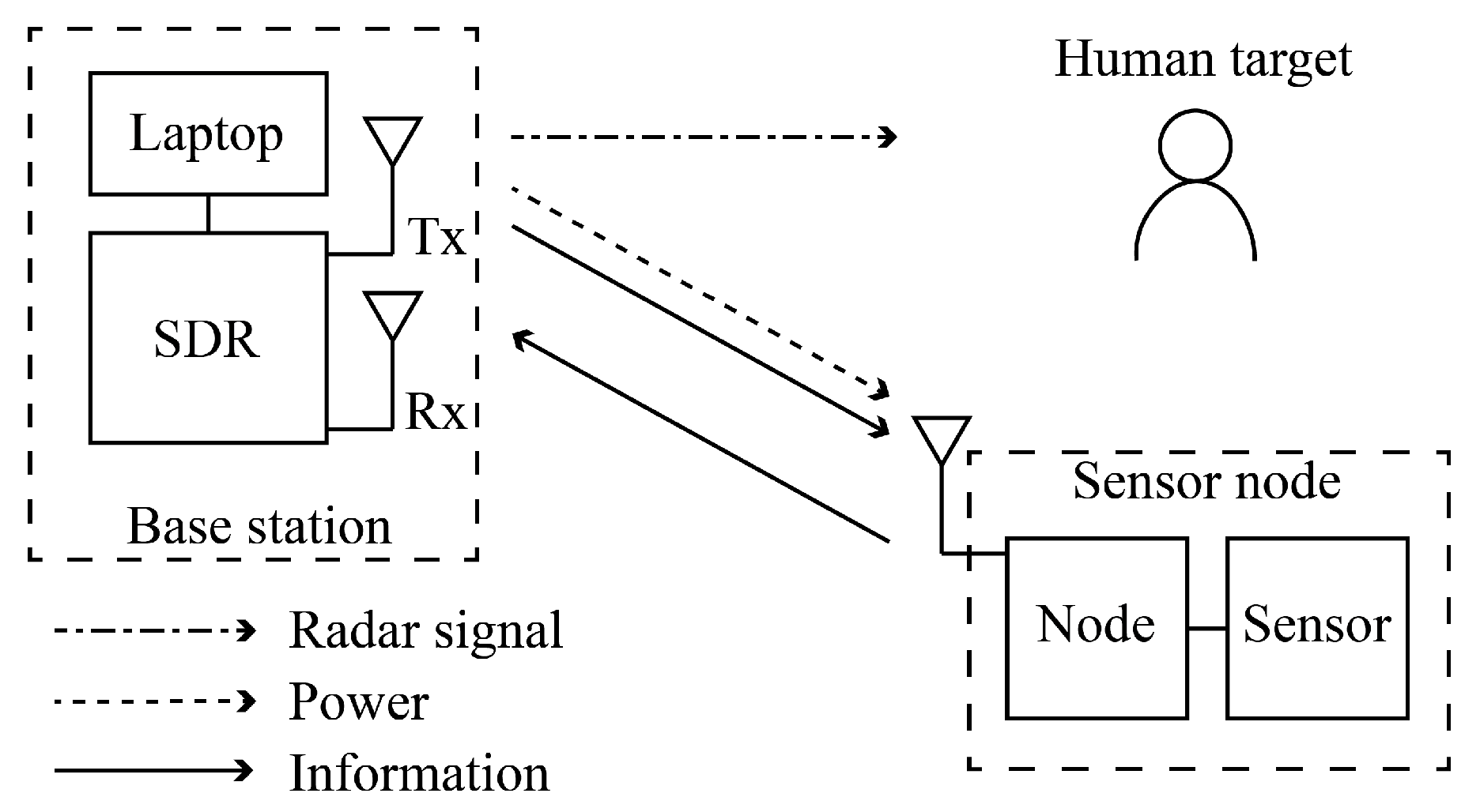
An SDR is adopted in this work as the base station to realize the three modes. As illustrated in
Figure 1, the base station transfers power in the downlink, and provides two-way communication for the sensor node. The sensor node consists of an energy-harvesting node and a sensor. Moreover, radar signals are transmitted to detect the speed and distance of the human target.
The existing indoor human detection radar mainly works in ISM bands such as 2.4 GHz, 24 GHz, and 60 GHz. There are two kinds of radar waveforms, pulse and continuous wave (CW). Research on pulse radar focuses on the ultra-wideband (UWB) pulse. The UWB bandwidth should exceed the minimum of 500 MHz or 20% of the amount of the center frequency. Single-tone CW can only measure the speed of moving targets, while frequency-modulated continuous wave (FMCW) is the main-stream continuous waveform that can simultaneously measure the speed and range of the target. An FMCW system transmits chirp signals whose frequency varies linearly with time, and calculates the target distance from the down converted received signals. The range resolution
depends on the bandwidth of the chirp, and can be calculated as:
where
c is the speed of light and
B is the bandwidth. As a narrower bandwidth leads to a lower range resolution, an FMCW radar usually has a bandwidth of 1–4 GHz in order to detect human targets [
26,
27]. By contrast, the performance of SDRs follows the requirements of a communication system, which has limited modulation bandwidth under strict standards. Most commercial SDRs have an RF bandwidth in the range of about 20–60 MHz, along with a frequency range under 6 GHz. Therefore, the above types of radar will produce compromised quality in terms of range resolution if they are realized on an SDR platform.
Different from these wideband waveforms, the stepped frequency continuous wave (SFCW) waveform sweeps through a bandwidth at discrete frequency values with a fixed step. The instantaneous bandwidth at every step is narrow, but when combined together, the effective bandwidth is large. Since SDR systems have a wide tunable range of center frequency and a relatively low modulation bandwidth, they are able to obtain a range resolution as high as main stream wideband radars by sweeping the carrier frequency. Compared to FMCW, which occupies the whole frequency band, SFCW only uses a narrow band at every frequency step. The idle frequencies in the spectrum can be utilized for coordination among the nodes of the network, which helps to reduce the impact brought about by incorporating radar functionality into the communication system [
28]. Meanwhile, a lower bandwidth of the receiver leads to receiving signals with less noise. Considering that the high sensitivity of the receiver is an advantage of the communication system, combining SFCW with SDR will present a satisfactory sensitivity and anti-interference performance.
However, it usually takes some time for the SDR to change the center frequency of the transmitting signal, which makes it time-consuming for the SFCW method to complete a measurement. To promptly obtain the state of the environment, a single-tone CW is required to check for moving objects instead. In this paper, a time splitting strategy is adopted to arrange the operation of three modes.
The power and information transfer are performed between the base station and the sensor node. A two-tone signal is adopted as the SWIPT waveform at the base station in the downlink. During the node rectification process, the harvested energy serves as the power supply, and the generated third order intermodulation (IM3) products are used as the carrier of the uplink. Data obtained from the sensor are modulated onto the IM3 products, and are then sent to the base station.
As illustrated in cycle 1 in
Figure 2, after some time interacting with the node, the base station switches to transmit single-tone CW to check whether there is a speed change in the environment. If no speed information is recovered from the reflected radar signals, the base station continues to send waveforms for SWIPT. Otherwise, cycle 1 is stopped and the base station switches to the radar mode cycle 2 on the right. The CW waveform continues. After the measured speed returns to zero, the base station sends the SFCW waveform to measure the distance between the target and the base station. The radar mode will repeat between CW and SFCW until both the speed and distance of the human target become undetectable within the detection area. Then, the base station resumes to the cycle of SWIPT, communication, and CW radar.
4. Experimental Investigations
4.1. Reference Path and Measurement Path
As shown in
Figure 3, a commercial SDR, ADALM-PLUTO SDR Active Learning Module (PlutoSDR), is adopted as the base station. The internal transceiver IC AD9363 has two separate LOs without time synchronization. Therefore, the additional phase term
in (14) is random and different for every frequency step, depending on the performance of the two LOs. To eliminate the random phase, a reference path is introduced in
Figure 3. The Tx port of PlutoSDR is connected to the input port of a HMC641ALC4 RF switch module, and the Rx port is connected to a ZFRSC-123-S+ power combiner. A short coaxial cable is connected from the RF3 port of the RF switch to the port 1 of power combiner via a 20 dB attenuator to form the reference path of signal. The Tx and Rx antennas are respectively connected to the RF1 port of the RF switch and port 2 of the power combiner to form the measurement path. At every frequency step of SFCW, the RF switch is switched to the RF3 port first, and then to the RF1 port while keeping the state of the transmitting chain unchanged. Signals from the reference path and measurement path pass through the power combiner in turn to the receiver. Since the Tx and Rx LOs are unchanged in this process, the term
is identical for the reference path and the measurement path. This extra random phase caused by the asynchronization between two chains can be eliminated by subtracting the phase of the reference path from that of the measurement path.
PlutoSDR has one transmitter and one receiver, with an RF coverage from 325 MHz to 6 GHz. The RF switch is controlled by a Geekcreit UNO R3 board via a DG412DJZ logic gate. Except for working in SFCW of the radar mode, the RF switch is always connected to port RF1 in the measurement path when the system is in SWIPT, communication, and CW radar modes.
4.2. SFCW Ranging
The overall experimental system is shown in
Figure 4a. Two GH1-18N horn antennas working at 1–18 GHz are used as the Tx and Rx antennas. The transmitting signal is amplified by a power amplifier before entering the Tx antenna, which enables the base station to provide sufficient power to the sensor node 200 cm away. The frequency range of the SFCW radar mode is 1–3 GHz, with a frequency step of 25 MHz. The carton with the metal plate is moved from 12.5 cm to 200 cm in front of the antennas. A distance list of 200 cm, 170 cm, 140 cm, 110 cm, 80 cm, 50 cm, and 20 cm is set with a 30 cm difference. Around distances of 170 cm, 140 cm, 110 cm, 80 cm, 50 cm, and 20 cm, seven points including the original distance, distances ±2.5 cm, ±5 cm, and ±7.5 cm away are measured. For the distance of 200 cm, four points at 200 cm, 200−2.5 cm, 200−5 cm, and 200−7.5 cm are measured. Therefore, there are 46 points in total within the range of 200 cm.
Figure 4b shows the results of SFCW ranging after calibration. The horizontal axis is the actual distance of the object. The vertical axis is the measured distance. The measurement error is less than 0.65 cm when the distance is more than 1 m, while within 1 m, the error tends to gradually increase as the distance from the object to the antennas decreases. When the distance is 15 cm, the error reaches a maximum of 11.25 cm. In the frequency range of the SFCW radar mode, as the object comes closer to the antennas within 1 m, it gradually leaves the far-field region. However, even if there is a deviation in the measured distance, the presence of the object near the antenna can still be detected, which will not cause misjudgment in the operation of cycle 2. It takes 0.9 s to measure a frequency step, including time to alter the carrier frequency of PlutoSDR, to change ports of the RF switch, and the time to perform the actual measurement. An 81-frequency SFCW requires 72.9 s to measure the distance, and 0.5 s for data processing.
In the test field, there is no obstruction from the front of the antenna to the door of the room. Therefore, the distance where the highest peak of the reflected power distribution is located is the distance between the target and the antenna. For furnished rooms, an additional calibration step has to be added, namely the room needs to be measured when no one is present. In that case, the distribution of reflected power is recorded as the calibration data that should be subtracted from the power distribution result in the presence of a target during data processing.
4.3. CW Speed Validation
The frequency of CW radar is set to the highest frequency of 6 GHz that the PlutoSDR can provide. As shown in the enlarged area of
Figure 5a, an IWR6843 antenna-on-package (AoP) radar module from Texas Instruments (TI) is adopted as a reference for speed measurement, and is placed next to the Tx horn antenna. Since this module works at 60 GHz, there is no interference between the two radars. The measured speed of a person walking back and forth in front of the horn antennas is presented in
Figure 5b. The PlutoSDR in radar mode provides a minimum detectable speed of 0.25 m/s.
4.4. SWIPT and Node Communication
Wireless power transfer and communication involve the base station and the sensor node. In this system, the PlutoSDR transfers power and information simultaneously to the sensor node in the downlink. The node receives power and sends back information in the uplink through backscattering. The downlink two-tone signal is generated using differential frequency shift keying (DFSK) at 2.538 GHz, with modulation frequencies of 100 kHz and 300 kHz. The node backscatter is at 2.5385 GHz, and amplitude shift keying (ASK) modulation is used. As shown in
Figure 6, the sensor node consists of a rectification and backscatter node, a CozIR-LP CO
sensor, a MSP430FR5994 LaunchPad Development Kit microcontroller unit (MCU), and a patch antenna. During the bi-directional communication, the base station sends information in the downlink, including a 3-byte preamble, a 2-byte nonce, and the ID of the sensor node. After passing the verification, the sensor node replies repeatedly with a message consisting of 3-byte preamble, the same ID and nonce, the 2-byte CO
sensor readout, and two 13-byte fixed values as padding. As illustrated in
Figure 7, there are 35 bytes in a message from the sensor node.
A typical usage of the sensor is to take a reading every minute. Therefore, the period of cycle 1 in
Figure 2 is set to 60 s, of which SWIPT lasts for the first 55 s. The rectified DC component charges a 1 F supercapacitor that acts as the power source of the MCU. The MCU reads data from the sensor once per cycle. From 50 to 55 s, the node demodulates instructions from the DFSK waveform and modulates information in the ASK waveform. Only in the presence of two-tone input can the data be modulated onto the IM3 carrier and reflected back to the base station. Then, CW radar mode is performed in the last 5 s of cycle 1. If this cycle is paused and the base station turns to cycle 2 in
Figure 2, the two-tone input at the node and the accompanying IM3 products for uplink modulation will be suspended as well.
The DFSK demodulation consumes 728
W in 0.7 s per cycle. The CozIR-LP CO
sensor requires 417
W to take a reading every minute under default settings. The uplink transmission process repeats the message 16 times, and a total of 4480 bits are sent in a period of 2 s. The two padding sequences with fixed values can be used for additional functions such as encryption keys. An average power of 264
W is consumed at the MCU for ASK modulation. The sensor node is placed 2 m away from the base station. The tag is presented in the previous work [
33], which has an average harvested power of 32.75
W when −10 dBm power is provided at the rectifier circuit. The measured maximum output power of PlutoSDR around 2.538 GHz is 3 dBm. In view of the 46 dB free-space path loss during propagation, a 23 dB power amplifier is connected between the Tx antenna and the RF1 port of the RF switch at the base station. The receive gain of PlutoSDR is set to a high level to obtain uplink information. Correspondingly, in order to prevent saturation of the input signal at receiver chain in the SFCW radar mode, the 20 dB attenuator is added in the reference path.
4.5. Time Sequence of the Three Modes
This system arranges the three modes by time splitting. First, the base station sends 55 s of SWIPT waveform to power the node and provides the IM3 component required by uplink backscattering. Starting from the 50th second, the node demodulates the downlink signal to acquire instructions for sensor access. Then, the data from the CO
sensor are modulated onto the IM3 product in ASK modulation, and are repeatedly sent to the base station within a period of 2 s. Correspondingly, the base station receives and demodulates the signal for 5 s, followed by 5 s of speed detection in CW radar mode. This 60-s process is illustrated in cycle 1 in
Figure 8. If no speed is detected from the current scene, cycle 1 continues. Otherwise, the base station turns to cycle 2 while maintaining the CW radar mode until the calculated speed returns to 0. Then, the succeeding SFCW radar mode measures the distance of the target. It takes 73.4 s to finish 81 frequency steps and the data processing. This is illustrated in cycle 2 in
Figure 8. If no target is detected within the detection range, the base station resumes to cycle 1. If the target remains in the scene, cycle 2 will repeat.
In situations where the power transmitted to the sensor is higher, more frequent insertion of the CW mode during the SWIPT process can be adopted, such as speed monitoring every 30 s. This leads to a smaller window of time during which a person is likely to be exposed to radiation. Further, the measuring time of the target range in SFCW radar mode is a result of the trade-off with the range resolution. A higher number of frequency steps means denser sampling over the spectrum. Reducing the number of steps can shorten the measuring time. However, the range will be accordingly divided into sparser cells, which leads to a reduced resolution.
5. Conclusions
The joint design of radar sensing, WPT, and communication is proposed in this paper. Based on a reconfigurable SDR, the base station is capable of powering and communicating with the nodes of an indoor wireless sensor network by SWIPT waveform and backscattering, and detecting the presence of a human through radar sensing. The energy harvested from the SWIPT waveform is accumulated in the sensor node as the power source. The three modes of the base station are achieved by time splitting strategy. During the 60-s cycle 1, the base station sends two-tone signals to simultaneously transfer power and information to the sensor node, and then receives information from the node through backscattering. The speed detection is executed at the end of every cycle to check the potential presence of a human object. When a moving object is detected, the power and information signals are halted, while the speed and distance measurements will continue until the moving object leaves the area. The minimum detectable speed is 0.25 m/s. A range resolution of 2.5 cm is achieved by means of SFCW on the PlutoSDR. A trade-off between measurement time and range resolution is essential when implementing radar function on communication platforms. This system is suitable for indoor environments where wireless sensor nodes are distributed and humans may appear, such as in hospitals, smart homes, and industrial plants. In future work, a multiple-input and multiple-output (MIMO) antenna array can be introduced to calculate the distance and orientation of the targets to achieve indoor localization.


