
Comparative Study of Discrete PI and PR Controller Implemented in SRG for Wind Energy Application: Theory and Experimentation


Abstract
:1. Introduction
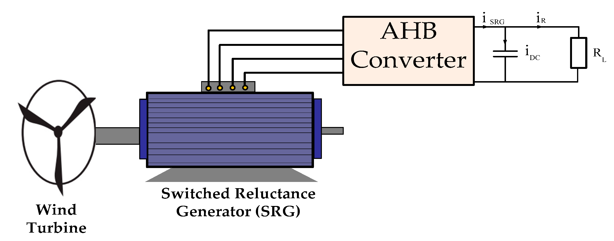
2. SRG Backgrounds
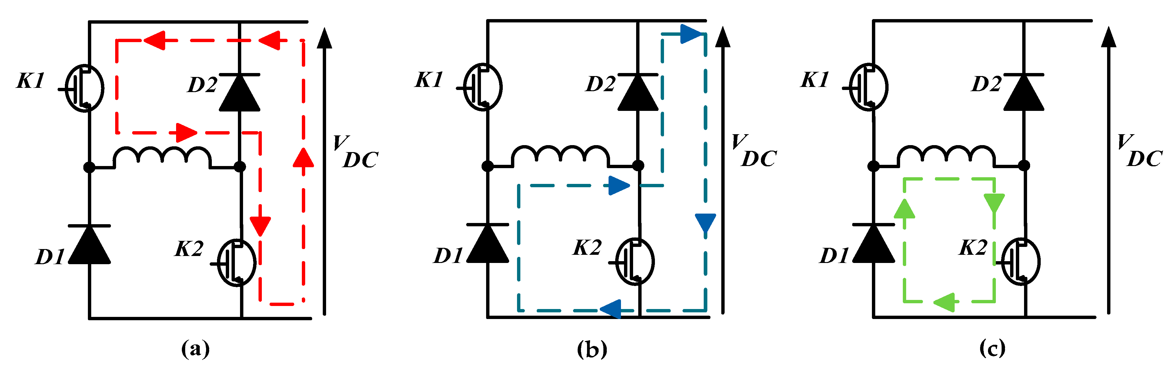
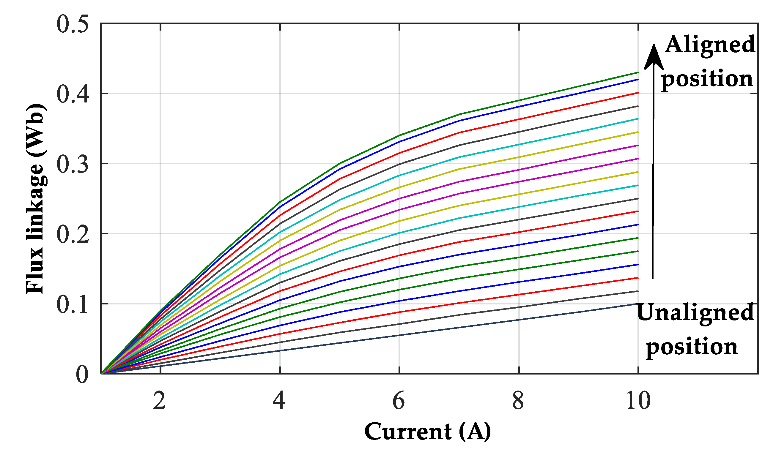
2.1. Mathematical Model and Analysis of SRG Operation
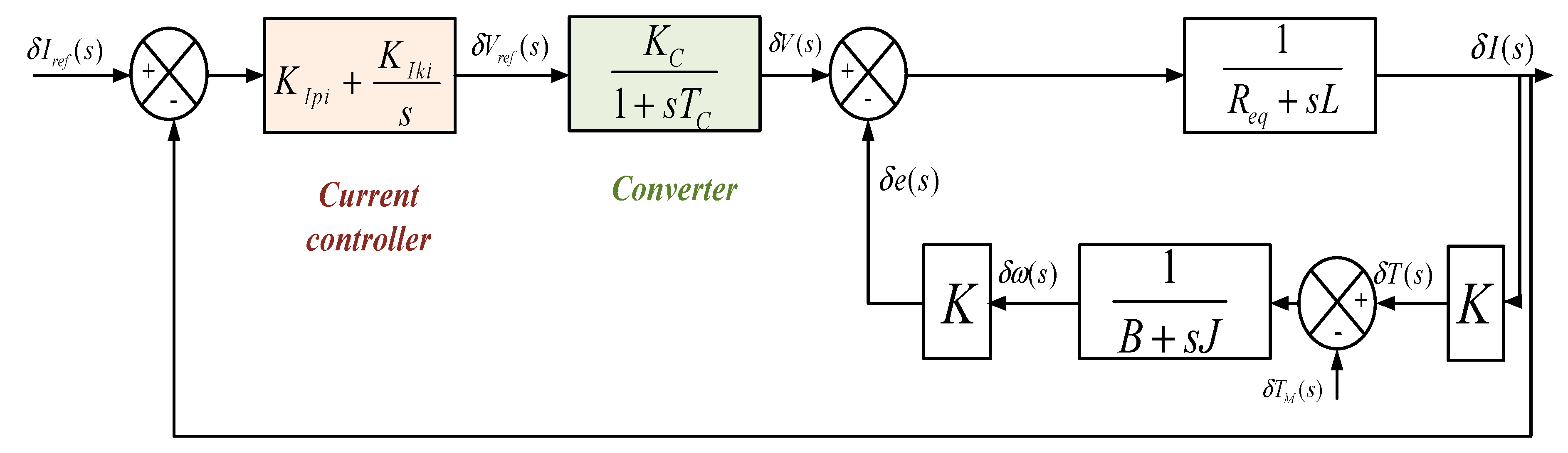
2.2. Simplification and Linearization of SRG
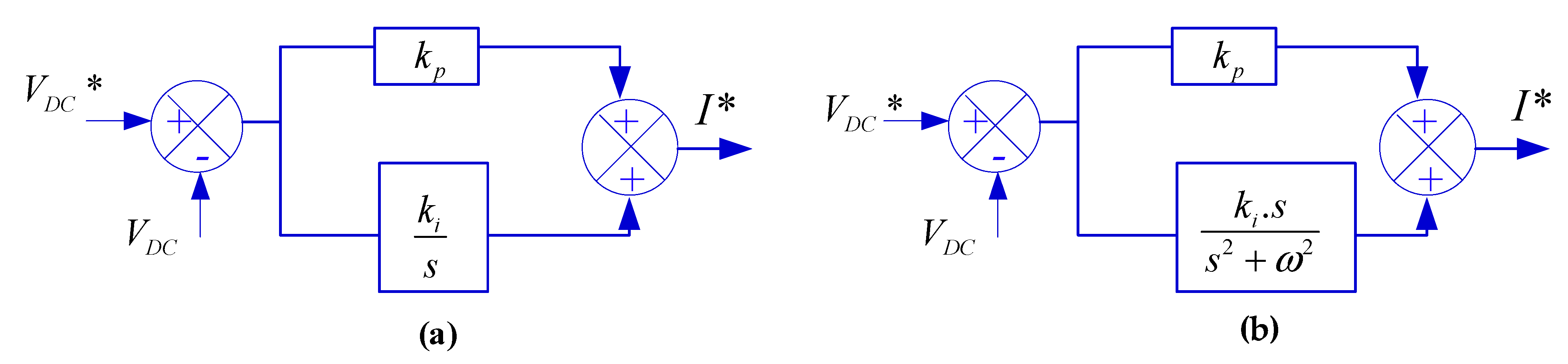
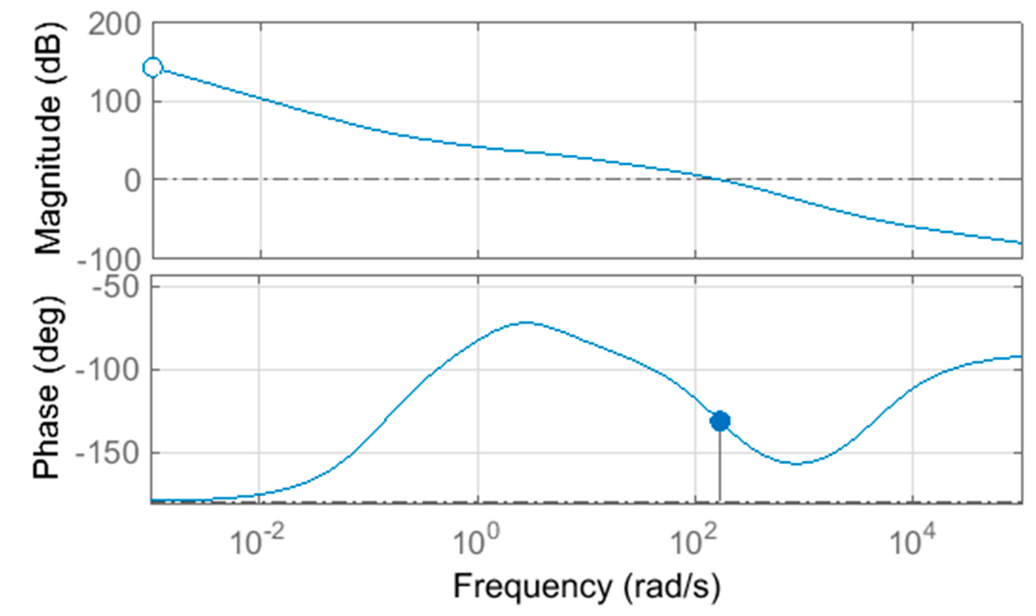
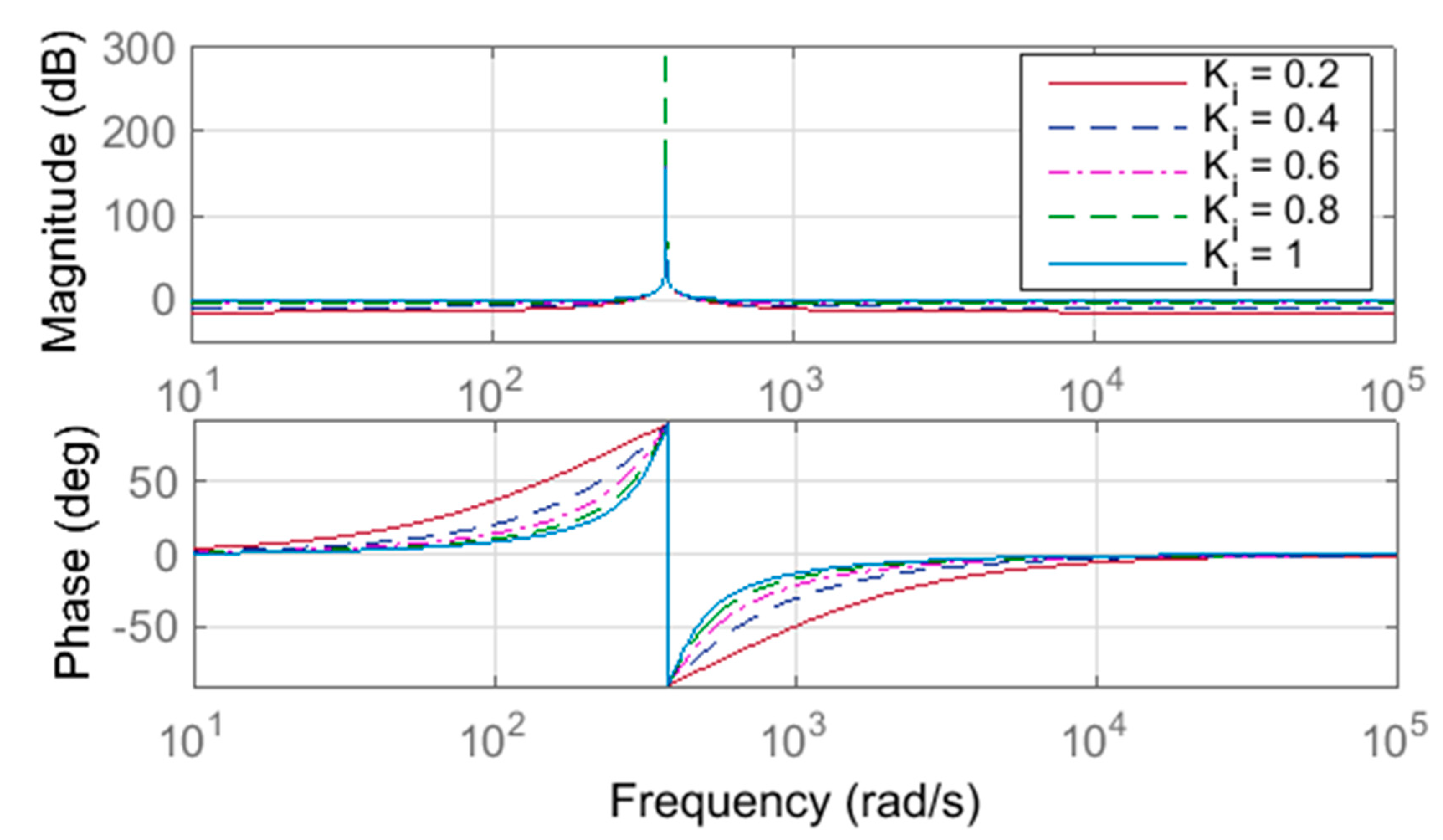
3. Voltage Controller Using PI and PR Controllers
4. Discrete Implementation
4.1. Implementation of PI Controller Using Discrete Transfer Function
4.2. Implementation of PR Controller Using Discrete Transfer Function
5. Experimental Results and Discussion
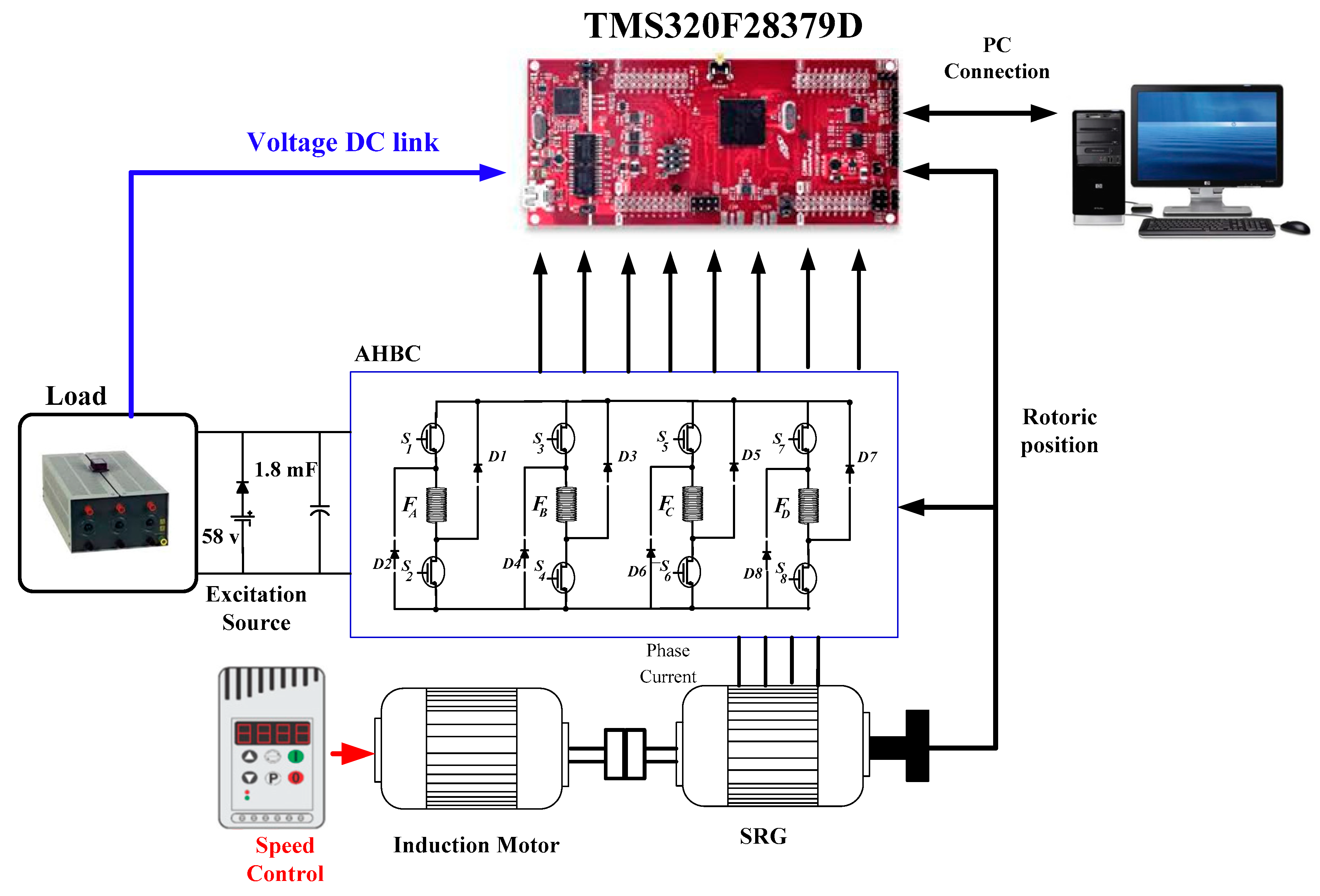
5.1. Experimentation
5.2. Experimental Results and Discussion
6. Conclusions
Author Contributions
Funding
Institutional Review Board Statement
Informed Consent Statement
Data Availability Statement
Conflicts of Interest
References
- Chen, Z.; Li, H. Overview of different wind generator systems and their comparisons. IET Renew. Power Gener. 2008, 2, 123–138. [Google Scholar] [CrossRef] [Green Version]
- Liu, Y.; Ren, L.; Li, Y.; Zhao, X. The industrial performance of wind power industry in China. Renew. Sustain. Energy Rev. 2015, 43, 644–655. [Google Scholar] [CrossRef]
- De Oliveira, A.L.; Capovilla, C.E.; Santana Casella, I.R.; Azcue-Puma, J.L.; Sguarezi Filho, A.J. Co-Simulation of an SRG Wind Turbine Control and GPRS/EGPRS Wireless Standards in Smart Grids. IEEE/CAA J. Autom. Sin. 2021, 8, 656–663. [Google Scholar] [CrossRef]
- Gao, S.; Wang, Q.; Li, G.; Qian, Z.; Zhou, S.; Li, Z. A Deflectable Switched Reluctance Motor/Generator for Wave Energy Conversion and Underwater Propulsion Systems. J. Electr. Eng. Technol. 2021, 16, 3157–3167. [Google Scholar] [CrossRef]
- Valdivia, V.; Todd, R.; Bryan, F.J.; Barrado, A.; Lazaro, A.; Forsyth, A.J. Behavioral Modeling of a Switched Reluctance Generator for Aircraft Power Systems. IEEE Trans. Ind. Electron. 2014, 61, 2690–2699. [Google Scholar] [CrossRef]
- Zhu, Y.; Wu, H.; Zhang, J. Regenerative Braking Control Strategy for Electric Vehicles Based on Optimization of Switched Reluctance Generator Drive System. IEEE Access 2020, 8, 76671–76682. [Google Scholar] [CrossRef]
- Diao, K.; Sun, X.; Lei, G.; Guo, Y.; Zhu, J. Multimode Optimization of Switched Reluctance Machines in Hybrid Electric Vehicles. IEEE Trans. Energy Convers. 2021, 36, 2217–2226. [Google Scholar] [CrossRef]
- Sun, X.; Diao, K.; Yang, Z. Performance improvement of a switched reluctance machine with segmental rotors for hybrid electric vehicles. Comput. Electr. Eng. 2019, 77, 244–259. [Google Scholar] [CrossRef]
- Bahy, M.; Nada, A.S.; Elbanna, S.H.; Shanab, M.A.M. Voltage control of switched reluctance generator using grasshopper optimization algorithm. Int. J. Power Electron. Drive Syst. 2020, 11, 75. [Google Scholar] [CrossRef] [Green Version]
- Chen, H.; Xu, D.; Deng, X. Control for Power Converter of Small-Scale Switched Reluctance Wind Power Generator. IEEE Trans. Ind. Electron. 2021, 68, 3148–3158. [Google Scholar] [CrossRef]
- Li, Z.; Yu, X.; Qian, Z.; Wang, X.; Xiao, Y.; Sun, H. Generation Characteristics Analysis of Deflection Type Double Stator Switched Reluctance Generator. IEEE Access 2020, 8, 196175–196186. [Google Scholar] [CrossRef]
- Sarr, A.; Bahri, I.; Berthelot, E.; Kebe, A.; Diallo, D. Switched Reluctance Generator for Low Voltage DC Microgrid Operation: Experimental Validation. Energies 2020, 13, 3032. [Google Scholar] [CrossRef]
- dos Santos Barros, T.A.; dos Santos Neto, P.J.; Nascimento Filho, P.S.; Moreira, A.B.; Ruppert Filho, E. An approach for switched reluctance generator in a wind generation system with a wide range of operation speed. IEEE Trans. Power Electron. 2017, 32, 8277–8292. [Google Scholar] [CrossRef]
- Araujo, W.R.H.; Reis, M.R.C.; Wainer, G.A.; Calixto, W.P. Efficiency Enhancement of Switched Reluctance Generator Employing Optimized Control Associated with Tracking Technique. Energies 2021, 14, 8388. [Google Scholar] [CrossRef]
- Lu, M.Z.; Jhou, P.H.; Liaw, C.M. Wind Switched-Reluctance Generator Based Microgrid with Integrated Plug-In Energy Support Mechanism. IEEE Trans. Power Electron. 2021, 36, 5496–5511. [Google Scholar] [CrossRef]
- Zan, X.; Ni, K.; Zhang, W.; Jiang, Z.; Cui, M.; Yu, D.; Zeng, R.A. New Control Strategy for SR Generation System Based on Modified PT Control. IEEE Access 2019, 7, 179720–179733. [Google Scholar] [CrossRef]
- Chirapo, K.A.C.; Oliveira, A.L.; Sguarezi Filho, A.J.; Pelizari, A.; Di Santo, S.G.; Costa, E.C.M. P+RES Controller Applied to the Direct Power Control of Switched Reluctance Generator. J. Control Autom. Electr. Syst. 2020, 31, 360–366. [Google Scholar] [CrossRef]
- Touati, Z.; Pereira, M.; Araújo, R.E.; Khedher, A. Improvement of Steady State Performance of Voltage Control in Switched Reluctance Generator: Experimental Validation. Machines 2022, 10, 103. [Google Scholar] [CrossRef]
- Chen, H.; Gu, J.J. Implementation of the Three-Phase Switched Reluctance Machine System for Motors and Generators. IEEE/ASME Trans. Mechatron. 2010, 15, 421–432. [Google Scholar] [CrossRef]
- Hao, C.; Xianjun, M.; Fang, X.; Tao, S.; Guilin, X. Fault tolerant control for switched reluctance motor drive. In Proceedings of the IEEE 2002 28th Annual Conference of the Industrial Electronics Society, IECON 02, Sevilla, Spain, 5–8 November 2002; Volume 2, pp. 1050–1054. [Google Scholar] [CrossRef]
- Touati, Z.; Mahmoud, I.; Khedher, A. Hysteresis Current Control of Switched Reluctance Generator. In Proceedings of the 2020 11th International Renewable Energy Congress (IREC), Hammamet, Tunisia, 29–31 October 2020; pp. 1–8. [Google Scholar] [CrossRef]
- Sunan, E.; Syed Muhammad Raza, K.; Goto, H.; Guo, H.-J.; Ichinokur, O. Instantaneous torque ripple control and maximum power extraction in a permanent magnet reluctance generator driven wind energy conversion system. In Proceedings of the XIX International Conference on Electrical Machines—ICEM 2010, Rome, Italy, 6–8 September 2010; pp. 1–6. [Google Scholar] [CrossRef]
- Ramu, K. Switched Reluctance Motor Drives: Modeling, Simulation, Analysis, Design, and Applications; CRC Press: Boca Raton, FL, USA, 2011. [Google Scholar]
- Yepes, A.G.; Freijedo, F.D.; Doval-Gandoy, J.; Lopez, O.; Malvar, J.; Fernandez-Comesana, P. On the discrete-time implementation of resonant controllers for active power filters. In Proceedings of the 35th Annual Conference of IEEE Industrial Electronics, Porto, Portugal, 3–5 November 2009. [Google Scholar] [CrossRef]


| Controller | Execution Time (μs) |
|---|---|
| PI | 0.66 |
| PR | 0.81 |
| Characteristics | Values |
|---|---|
| Output power | 250 W |
| Maximum current | 3 A |
| Inductance (aligned position) | 0.14 H |
| Inductance (unaligned position) | 0.021 H |
| Viscous friction | 0.01 Nms |
| Moment of inertia | 0.006 Kgm2 |
| Resistance of phase winding | 5 Ω |
| Controller | ||
|---|---|---|
| Parameters | PI | PR |
| Kp | 0.9 | 100 |
| Ki | 0.09 | 1 |
| Control Schemes | Rise Time (s) | Settling Time (s) | Peak Overshoot | Voltage Ripple (%) |
|---|---|---|---|---|
| PI | 0.40 | 0.92 | 5.6 | 2.88 |
| PR | 0.22 | 0.52 | 0 | 2.85 |
| 500 (rpm) | 600 (rpm) | 700 (rpm) | 800 (rpm) | |||||
|---|---|---|---|---|---|---|---|---|
| PI | PR | PI | PR | PI | PR | PI | PR | |
| Rise time (s) | 1.3 | 0.84 | 0.66 | 0.34 | 0.45 | 0.38 | 0.64 | 0.45 |
| Settling time (s) | 1.68 | 1.49 | 1.02 | 0.48 | 1 | 0.62 | 1.2 | 0.82 |
| Peak overshoot | 0.91 | 0 | 3.8 | 0 | 3.4 | 0 | 3.83 | 0 |
| Voltage ripple (%) | 4.7 | 4.5 | 4.28 | 3.8 | 3.06 | 2.79 | 3.58 | 3.4 |
Publisher’s Note: MDPI stays neutral with regard to jurisdictional claims in published maps and institutional affiliations. |
© 2022 by the authors. Licensee MDPI, Basel, Switzerland. This article is an open access article distributed under the terms and conditions of the Creative Commons Attribution (CC BY) license (https://creativecommons.org/licenses/by/4.0/).
Share and Cite
Touati, Z.; Pereira, M.; Araújo, R.E.; Khedher, A. Comparative Study of Discrete PI and PR Controller Implemented in SRG for Wind Energy Application: Theory and Experimentation. Electronics 2022, 11, 1285. https://doi.org/10.3390/electronics11081285
Touati Z, Pereira M, Araújo RE, Khedher A. Comparative Study of Discrete PI and PR Controller Implemented in SRG for Wind Energy Application: Theory and Experimentation. Electronics. 2022; 11(8):1285. https://doi.org/10.3390/electronics11081285
Chicago/Turabian StyleTouati, Zeineb, Manuel Pereira, Rui Esteves Araújo, and Adel Khedher. 2022. "Comparative Study of Discrete PI and PR Controller Implemented in SRG for Wind Energy Application: Theory and Experimentation" Electronics 11, no. 8: 1285. https://doi.org/10.3390/electronics11081285