
Modeling and Extended State Observer-Based Backstepping Control of Underwater Electro Hydrostatic Actuator with Pressure Compensator and External Load


Abstract
:1. Introduction
- A new underwater electro hydrostatic actuator model with the pressure compensator. If the sensors can measure the pressure compensator state, the disturbance of the compensator could be compensated based on the model; otherwise, it is observed by extending the state observer.
- The backstepping controller combined two low-order extended state observers for the underwater EHA system. The uncertain external load and the disturbance effect caused by the pressure compensator are estimated and then compensated by feedforward. Combining the backstepping method leads to transient motion tracking and final tracking performance.
2. Materials and Methods
2.1. Modeling and Problem Formulation
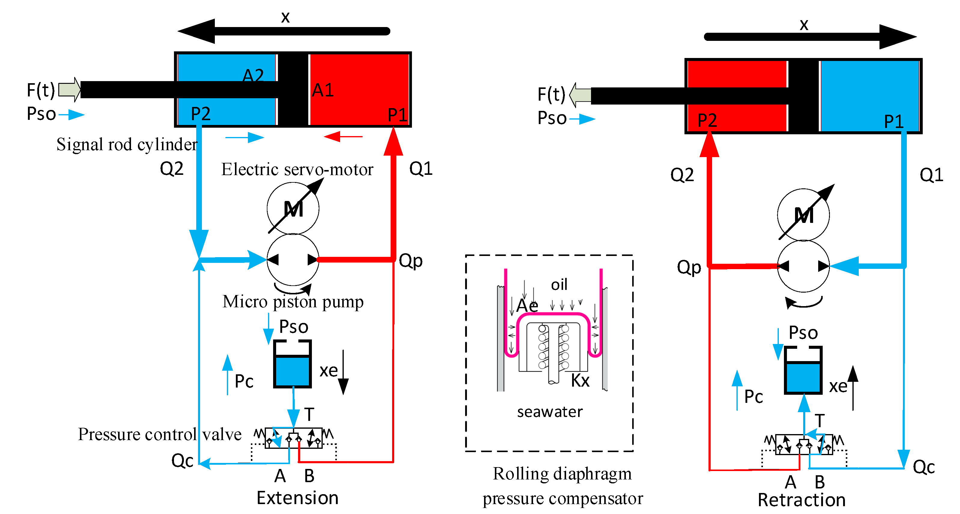
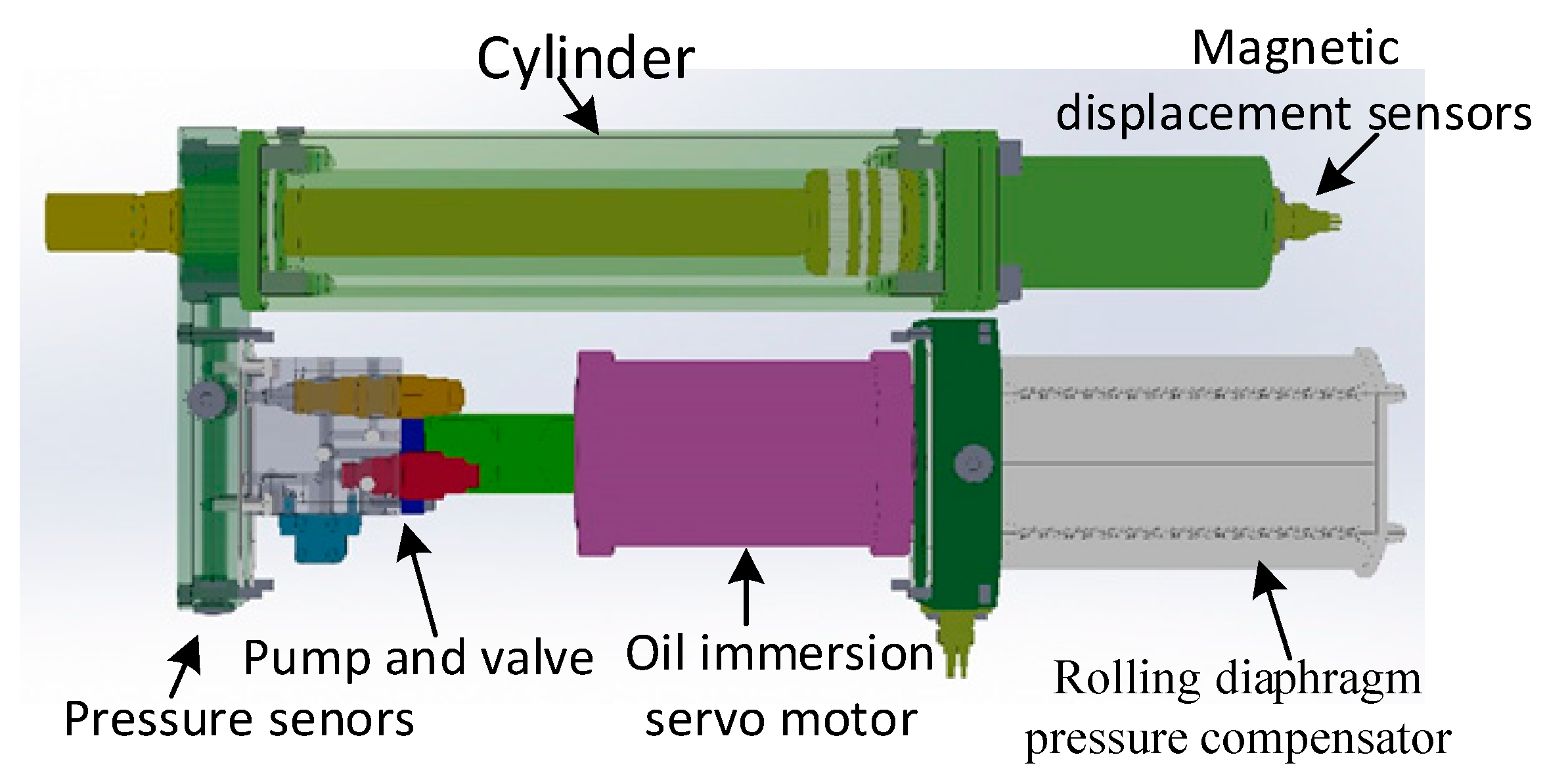
2.1.1. System Description
2.1.2. Modeling of the Underwater EHA
- 1.
- Dynamic of cylinder
- 2.
- Flows rate with the pressure compensator
- 3.
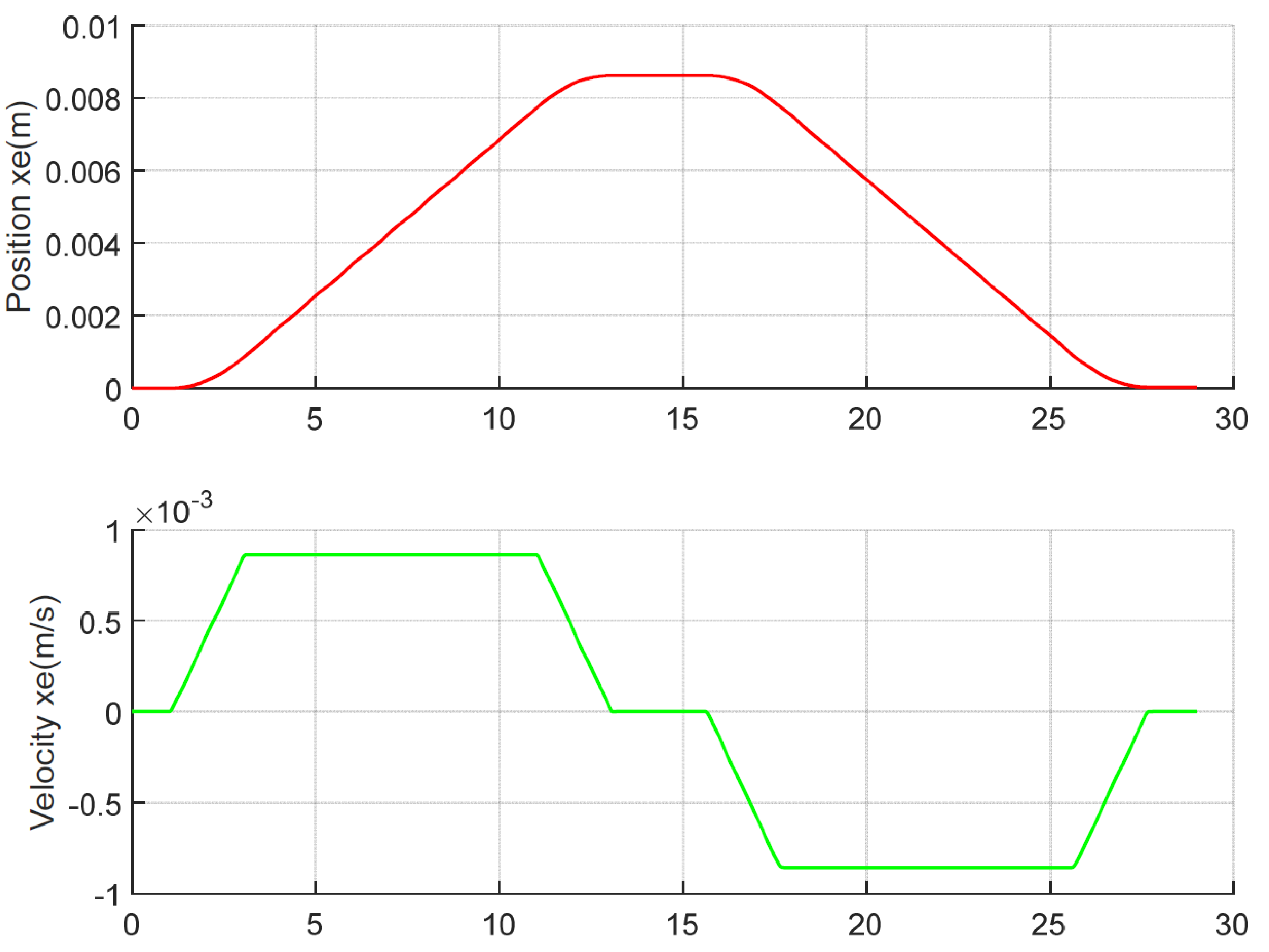
- Simple dynamic of the pressure compensator
2.1.3. Problem Formulation
2.2. Backstepping Control Design with Extended State Observer
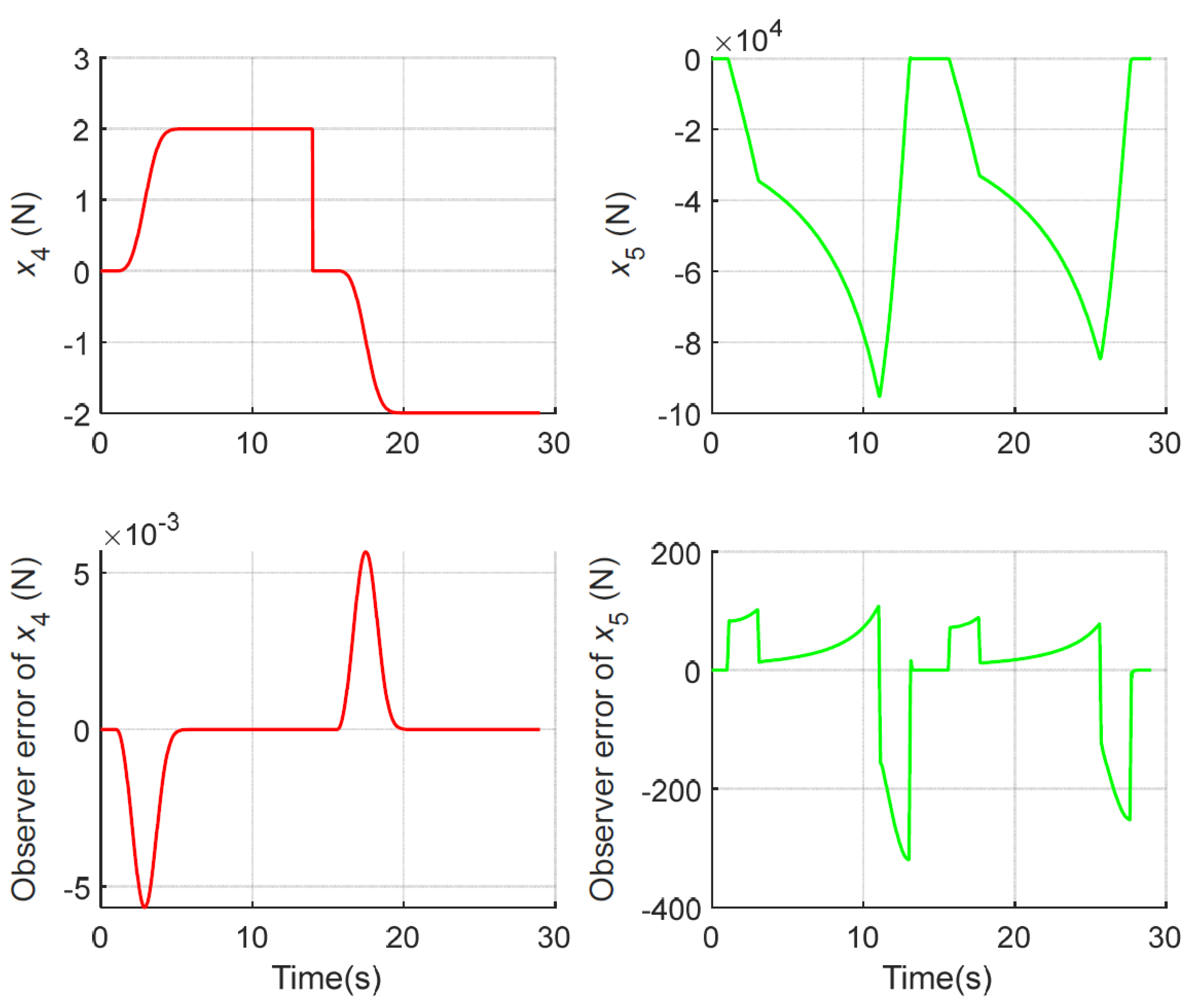
2.2.1. Extend State Observer Design
2.2.2. Backstepping Controller Design
3. Results
3.1. Simulation Setup
- (1)
- In the simulation model: , .
- (2)
- In controller and observer: , .
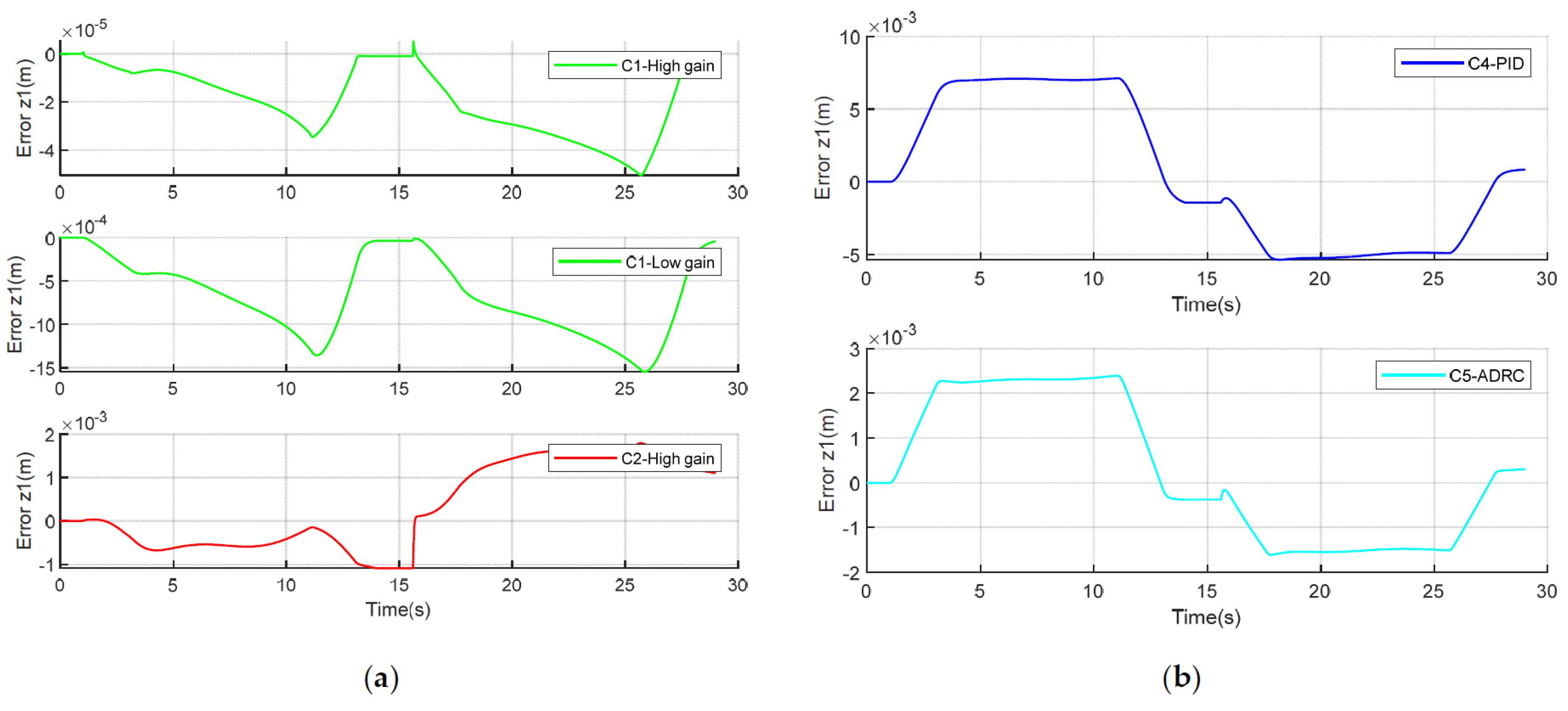
- (1)
- C1: Backstepping controller with an extending state observer.
- (2)
- C2: The classic backstepping controller.
- (3)
- C4: The contractional PID controller.
- (4)
- C5: The ADRC (active disturbance rejection control) controller.
3.2. Comparative Results
4. Discussion
5. Conclusions
Author Contributions
Funding
Acknowledgments
Conflicts of Interest
References
- Alle, N.; Hiremath, S.S.; Makaram, S.; Subramaniam, K.; Talukdar, A. Review on electro hydrostatic actuator for flight control. Int. J. Fluid Power 2016, 17, 125–145. [Google Scholar] [CrossRef]
- Kumar, M. A survey on electro hydrostatic actuator: Architecture and way ahead. Mater. Today Proc. 2021, 45, 6057–6063. [Google Scholar] [CrossRef]
- Maré, J.-C.; Fu, J. Review on signal-by-wire and power-by-wire actuation for more electric aircraft. Chin. J. Aeronaut. 2017, 30, 857–870. [Google Scholar] [CrossRef]
- Sun, W.; Wang, X.; Zhang, C. A Model-Free Control Strategy for Vehicle Lateral Stability with Adaptive Dynamic Programming. IEEE Trans. Ind. Electron. 2020, 67, 10693–10701. [Google Scholar] [CrossRef]
- Sivčev, S.; Coleman, J.; Omerdić, E.; Dooly, G.; Toal, D. Underwater manipulators: A review. Ocean. Eng. 2018, 163, 431–450. [Google Scholar] [CrossRef]
- Fu, Y.; Han, X.; Sepehri, N.; Zhou, G.; Fu, J.; Yu, L.; Yang, R. Design and performance analysis of position-based impedance control for an electrohydrostatic actuation system. Chin. J. Aeronaut. 2018, 31, 584–596. [Google Scholar] [CrossRef]
- Law, M.; Wabner, M.; Colditz, A.; Kolouch, M.; Noack, S.; Ihlenfeldt, S. Active vibration isolation of machine tools using an electro-hydraulic actuator. CIRP J. Manuf. Sci. Technol. 2015, 10, 36–48. [Google Scholar] [CrossRef]
- Navatha, A.; Bellad, K.; Hiremath, S.S.; Karunanidhi, S. Dynamic Analysis of Electro Hydrostatic Actuation System. Procedia Technol. 2016, 25, 1289–1296. [Google Scholar] [CrossRef] [Green Version]
- Belloli, D.; Previdi, F.; Savaresi, S.M.; Cologni, A.; Zappella, M. Modeling and Identification of an Electro-Hydrostatic Actuator. IFAC Proc. Vol. 2010, 43, 620–625. [Google Scholar] [CrossRef] [Green Version]
- Guo, Q.; Zhang, Y.; Celler, B.G.; Su, S.W. State-Constrained Control of Single-Rod Electrohydraulic Actuator with Parametric Uncertainty and Load Disturbance. IEEE Trans. Contr. Syst. Technol. 2018, 26, 2242–2249. [Google Scholar] [CrossRef]
- Li, S.; Du, X.; Zhang, L.; Chen, K.; Wang, S. Study on dynamic characteristics of underwater pressure compensator considering nonlinearity. Mech. Sci. 2020, 11, 183–192. [Google Scholar] [CrossRef]
- Wu, J.-B.; Li, L.; Wei, W. Research on dynamic characteristics of pressure compensator for deep-sea hydraulic system. Proc. Inst. Mech. Eng. Part M J. Eng. Marit. Environ. 2021, 236, 19–33. [Google Scholar] [CrossRef]
- Guo, Q.; Zhang, Y.; Celler, B.G.; Su, S.W. Backstepping Control of Electro-Hydraulic System Based on Extended-State-Observer With Plant Dynamics Largely Unknown. IEEE Trans. Ind. Electron. 2016, 63, 6909–6920. [Google Scholar] [CrossRef]
- Sun, W.; Pan, H.; Gao, H. Filter-Based Adaptive Vibration Control for Active Vehicle Suspensions with Electrohydraulic Actuators. IEEE Trans. Veh. Technol. 2016, 65, 4619–4626. [Google Scholar] [CrossRef]
- Mohanty, A.; Yao, B. Integrated Direct/Indirect Adaptive Robust Control of Hydraulic Manipulators with Valve Deadband. IEEE/ASME Trans. Mechatron. 2011, 16, 707–715. [Google Scholar] [CrossRef]
- Yao, B.; Bu, F.; Reedy, J.; Chiu, G.-C. Adaptive robust motion control of single-rod hydraulic actuators: Theory and experiments. IEEE/ASME Trans. Mechatron. 2000, 5, 79–91. [Google Scholar] [CrossRef]
- Lyu, L.; Chen, Z.; Yao, B. Advanced Valves and Pump Coordinated Hydraulic Control Design to Simultaneously Achieve High Accuracy and High Efficiency. IEEE Trans. Contr. Syst. Technol. 2021, 29, 236–248. [Google Scholar] [CrossRef]
- Temporelli, R.; Boisvert, M.; Micheau, P. Control of an Electromechanical Clutch Actuator Using a Dual Sliding Mode Controller: Theory and Experimental Investigations. IEEE/ASME Trans. Mechatron. 2019, 24, 1674–1685. [Google Scholar] [CrossRef]
- Shen, W.; Wang, J. An integral terminal sliding mode control scheme for speed control system using a double-variable hydraulic transformer. ISA Trans. 2019, S0019-0578(19)30414-8. [Google Scholar] [CrossRef]
- Kim, M.J.; Chung, W.K. Disturbance-Observer-Based PD Control of Flexible Joint Robots for Asymptotic Convergence. IEEE Trans. Robot. 2015, 31, 1508–1516. [Google Scholar] [CrossRef]
- Lee, W.; Kim, M.J.; Chung, W.K. Asymptotically Stable Disturbance Observer-Based Compliance Control of Electrohydrostatic Actuators. IEEE/ASME Trans. Mechatron. 2020, 25, 195–206. [Google Scholar] [CrossRef]
- Ahn, K.K.; Nam, D.N.C.; Jin, M. Adaptive Backstepping Control of an Electrohydraulic Actuator. IEEE/ASME Trans. Mechatron. 2014, 19, 987–995. [Google Scholar] [CrossRef]
- Yao, J.; Deng, W. Active disturbance rejection adaptive control of uncertain nonlinear systems: Theory and application. Nonlinear Dyn. 2017, 89, 1611–1624. [Google Scholar] [CrossRef]
- Yao, J.; Jiao, Z.; Ma, D. Adaptive Robust Control of DC Motors with Extended State Observer. IEEE Trans. Ind. Electron. 2014, 61, 3630–3637. [Google Scholar] [CrossRef]
- Luo, C.; Yao, J.; Gu, J. Extended-state-observer-based output feedback adaptive control of hydraulic system with continuous friction compensation. J. Frankl. Inst. 2019, 356, 8414–8437. [Google Scholar] [CrossRef]
- Lin, T.; Lin, Y.; Ren, H.; Chen, H.; Li, Z.; Chen, Q. A double variable control load sensing system for electric hydraulic excavator. Energy 2021, 223, 119999. [Google Scholar] [CrossRef]
- Lyu, L.; Chen, Z.; Yao, B. Development of Pump and Valves Combined Hydraulic System for Both High Tracking Precision and High Energy Efficiency. IEEE Trans. Ind. Electron. 2019, 66, 7189–7198. [Google Scholar] [CrossRef]
- Cheng, M.; Zhang, J.; Xu, B.; Ding, R.; Wei, J. Decoupling Compensation for Damping Improvement of the Electrohydraulic Control System with Multiple Actuators. IEEE/ASME Trans. Mechatron. 2018, 23, 1383–1392. [Google Scholar] [CrossRef]
- Ding, R.; Cheng, M.; Jiang, L.; Hu, G. Active Fault-Tolerant Control for Electro-Hydraulic Systems with an Independent Metering Valve Against Valve Faults. IEEE Trans. Ind. Electron. 2021, 68, 7221–7232. [Google Scholar] [CrossRef]
- Kim, M.J.; Beck, F.; Ott, C.; Albu-Schaffer, A. Model-Free Friction Observers for Flexible Joint Robots with Torque Measurements. IEEE Trans. Robot. 2019, 35, 1508–1515. [Google Scholar] [CrossRef] [Green Version]
- Helian, B.; Chen, Z.; Yao, B.; Lyu, L.; Li, C. Accurate Motion Control of a Direct-Drive Hydraulic System with an Adaptive Nonlinear Pump Flow Compensation. IEEE/ASME Trans. Mechatron. 2021, 26, 2593–2603. [Google Scholar] [CrossRef]
- Helian, B.; Chen, Z.; Yao, B. Precision Motion Control of a Servomotor-Pump Direct-Drive Electrohydraulic System with a Nonlinear Pump Flow Mapping. IEEE Trans. Ind. Electron. 2020, 67, 8638–8648. [Google Scholar] [CrossRef]
- Ren, G.; Esfandiari, M.; Song, J.; Sepehri, N. Position Control of an Electrohydrostatic Actuator with Tolerance to Internal Leakage. IEEE Trans. Contr. Syst. Technol. 2016, 24, 2224–2232. [Google Scholar] [CrossRef]
- Cai, Y. Research on Robust Control of Electro-Hydrostatic Actuators and Secondary Controlled Systems Based on Quantitative Feedback Theory. Ph.D. Thesis, Northeastern University, Shenyang, China, 2017. (In Chinese). [Google Scholar]
- Han, J. From PID to Active Disturbance Rejection Control. IEEE Trans. Ind. Electron. 2009, 56, 900–906. [Google Scholar] [CrossRef]


| Parameter | Value | Parameter | Value |
|---|---|---|---|
| 100 kg | 7 × 10⁸ | ||
| 2000 N/(m/s) | 4.5 × 10⁶ Pa | ||
| A1 | 2.3758 × 10⁻³ m2 | 0.0716 m3 | |
| A2 | 1.76 × 10⁻³ m2 | 3.1 N/mm | |
| Ae | 14.314 × 10⁻³ m2 |
| Controllers | |||
|---|---|---|---|
| C1 high gain | 0.538 | ||
| C1 low gain | 19.172 | ||
| C2 high gain | 25.164 | ||
| C4 PID | 125 | ||
| C5 ADRC [35] | 39.54 |
Publisher’s Note: MDPI stays neutral with regard to jurisdictional claims in published maps and institutional affiliations. |
© 2022 by the authors. Licensee MDPI, Basel, Switzerland. This article is an open access article distributed under the terms and conditions of the Creative Commons Attribution (CC BY) license (https://creativecommons.org/licenses/by/4.0/).
Share and Cite
Nie, Y.; Liu, J.; Lao, Z.; Chen, Z. Modeling and Extended State Observer-Based Backstepping Control of Underwater Electro Hydrostatic Actuator with Pressure Compensator and External Load. Electronics 2022, 11, 1286. https://doi.org/10.3390/electronics11081286
Nie Y, Liu J, Lao Z, Chen Z. Modeling and Extended State Observer-Based Backstepping Control of Underwater Electro Hydrostatic Actuator with Pressure Compensator and External Load. Electronics. 2022; 11(8):1286. https://doi.org/10.3390/electronics11081286
Chicago/Turabian StyleNie, Yong, Jiajia Liu, Zhenhua Lao, and Zheng Chen. 2022. "Modeling and Extended State Observer-Based Backstepping Control of Underwater Electro Hydrostatic Actuator with Pressure Compensator and External Load" Electronics 11, no. 8: 1286. https://doi.org/10.3390/electronics11081286