
An Artificial Visual System for Motion Direction Detection Based on the Hassenstein–Reichardt Correlator Model


1
Division of Electrical Engineering and Computer Science, Kanazawa University, Kakuma-machi, Kanazawa 920-1192, Japan
2
Faculty of Electrical, Information and Communication Engineering, Kanazawa University, Kakuma-machi, Kanazawa 920-1192, Japan
3
Department of Intelligence Information System, University of Toyama, 3190 Gofuku, Toyama 930-8555, Japan
*
Authors to whom correspondence should be addressed.
Electronics 2022, 11(9), 1423; https://doi.org/10.3390/electronics11091423
Submission received: 20 March 2022
/
Revised: 25 April 2022
/
Accepted: 26 April 2022
/
Published: 28 April 2022
(This article belongs to the Special Issue Feature Papers in Computer Science & Engineering)
Abstract
:The perception of motion direction is essential for the survival of visual animals. Despite various theoretical and biophysical investigations that have been conducted to elucidate directional selectivity at the neural level, the systemic mechanism of motion direction detection remains elusive. Here, we develop an artificial visual system (AVS) based on the core computation of the Hassenstein–Reichardt correlator (HRC) model for global motion direction detection. With reference to the biological investigations of Drosophila, we first describe a local motion-sensitive, directionally detective neuron that only responds to ON motion signals with high pattern contrast in a particular direction. Then, we use the full-neurons scheme motion direction detection mechanism to detect the global motion direction based on our previous research. The mechanism enables our AVS to detect multiple directions in a two-dimensional view, and the global motion direction is inferred from the outputs of all local motion-sensitive directionally detective neurons. To verify the reliability of our AVS, we conduct a series of experiments and compare its performance with the time-considered convolution neural network (CNN) and the EfficientNetB0 under the same conditions. The experimental results demonstrated that our system is reliable in detecting the direction of motion, and among the three models, our AVS has better motion direction detection capabilities.
1. Introduction
For numerous animals, vision plays a critical role in receiving information from the outside world [1]. In recent decades, scientists have discovered separate visual processing systems in different species of animals, and each system is dedicated to processing its own interesting features [2,3,4]. Among these functional processing systems, motion perception is considered the most basic visual capability because of its widespread presence in the visual system, ranging from vertebrates to invertebrates [5]. Research on motion perception can be dated back to 1894, when Exner first presented a drawing of motion detection neural networks [6]. In 1912, Wertheimer introduced the Phi phenomenon and revealed that motion can be seen in two stationary flashes [7]. The discovery that optic nerve fibers’ activities can be recorded by the discharge of impulses makes it possible for biologists to conduct research on single ganglion cells [8,9,10,11]. After the observation of many retinal ganglion cells in the receptive field with light-specific responses [12,13], neurons that respond to movement in a direction-selective way have been observed in both the mammalian retina (direction-selective ganglion cells, DSGCs) and the insect optic lobe (lobula plate tangential cells, LPTCs) [14,15].
In order to understand the mechanism underlying signal processing in direction-selective neurons (DSNs), scientists have proposed a variety of computational models [16,17,18,19,20]. These models are summarized by Borst and Egelhaaf and have been divided into two main categories: correlation-type models and gradient-type models [21,22]. The gradient-type models, which originated from the computer vision, calculate motion through the spatial and the temporal gradient of the moving image. In contrast to the gradient-type model, the biological motion detectors correlate the brightness values measured at two adjacent image points with each other after one of them has been filtered in time. In 1956, Hassenstein and Reichardt proposed the first biologically based correlation-type model, the so-called HRC model [16]. The HRC model is considered the modern theoretical framework for motion direction detection because it encourages people to understand the selectivity of motion direction from the perspective of neural computations [23,24]. As advances in techniques develop, more details about DSNs’ neuronal circuits have been investigated [25,26,27,28,29,30,31,32,33,34,35,36]. Now, we have evidence to believe that motion detection in flies can be computed by preferred direction enhancement, and the direction selectivity underlying the fly’s neural circuits can be well-explained by the HRC models [37].
Although direction selectivity in visual pathways has been researched in recent decades, the exact mechanism of global motion direction detection has remained a puzzle [31,38]. To settle this issue, we propose an artificial visual system (AVS) to further understand the detecting mechanism of motion direction. First, we assume that the motion can be observed in two time-continuous stationary images. Based on the research of Adelson and Bergen [39], we build our dataset with a sufficiently high sampling frequency so that the step size of the object’s movement is fixed. Then, we cite the concept of simple cells [40] and propose a local motion-sensitive directionally detective neuron to detect motion in a particular direction. In our previous works, we have conducted research on the motion direction detection mechanism and the orientation detection mechanism, which may exist in the biological visual system [41,42,43,44,45,46]. In studies of mammalian motion vision, we relied on the dendritic computation of direction-selective ganglion cells and Barlow’s retina inhibitory scheme in direction-selective ganglion cells, respectively, to successfully detect the global motion direction using the multi-neurons scheme scanning mechanism [41,42]. In this paper, we build our neurons to respond to the ON motion signals with a high pattern contrast. The proposed neuron, based on the core computation of the HRC model, detects the motion direction with two spatiotemporally separated photoreceptors. Furthermore, the proposed neuron can be easily extended to two-dimensional multi-direction detections; for simplicity, eight neurons were employed to detect eight potential directions of motion. Finally, we used the full-neurons scheme motion direction detection mechanism to detect the global direction of motion. Inspired by the fly’s visual system, we assume that each light spot in the visual field can provide signals to an array of local motion-sensitive directionally detective neurons and introduce the activation strength to obtain the global direction of motion. Similar to the way LPTCs sum signals from medulla columns and generate a wide-field response [33], we summed the activated number of neurons that detect the same direction and mark the maximum value as the global motion direction. To verify the reliability of our AVS, we conducted a series of experiments. The experimental results show that our AVS not only detects the global motion direction regardless of sizes and shapes, but also performs well in noisy situations. Moreover, we compare the system’s performance with the time-considered CNN and the EfficientNetB0 under the same conditions. The detection results show that our AVS not only beats the CNN and the EfficientNetB0 on motion direction detection in learning costs, but also in noise resistance.
2. Materials and Methods
The fly’s nervous system, because it has far fewer neurons than the mammalian nervous system, has always been the focus of research on vision [29]. In this section, we introduce our AVS with reference to biophysical investigations of Drosophila.
2.1. Hassenstein–Reichardt Correlator Model
The HRC model was first proposed by analyzing the optomotor behavior of the Chlorophanus viridis beetle [16]. It consists of two mirror-symmetrical subunits, and each subunit has its own preferred direction (Figure 1a) [21,22,23,24]. In 2010, Borst and his laboratory members set a tethered fly in the center of a striped drum and observed the existence of optomotor responses in both directions by rotating the striped drum in opposite ways [29]. Such experimental results have been supported by other research [47,48,49,50,51], providing evidence that the HRC model is a qualified computational model to explain motion detection in Drosophila.
Theoretically, the HRC model is an excitatory scheme of biologically based computational models [37]. In its most basic form, the HRC model receives inputs from two spatially separated positions, one of which has been temporally delayed [52]. Figure 1b shows a rightward motion detector of the HRC model. The detector will respond to a rightward shift but will evoke no response in a leftward shift. For further explanation, in Figure 1c, we use a yellow dot to indicate the light spot’s position at time T and a red dot to indicate that light spot’s position at time T + ∆T. If we mathematically define the value of signals in the rightward motion detector as 1, the computation in its preferred direction will be 1 × 1 = 1. Therefore, the rightward motion detector will evoke a response. However, the detector will fail to evoke any responses in detecting the stimuli moving in its null direction because the calculation in it is 0 × 1 = 0.
2.2. Local Motion-Sensitive Directionally Detective Neurons
In a fly’s visual system, LPTCs serve as directionally selective neurons that produce a wide-field response [47]. They depolarize when motion appears in their preferred direction and hyperpolarize when objects move in the null direction. However, LPTCs do not compute the local motion direction themselves. This raises the question of which neuron can functionally compute the local motion signals upstream to LPTCs. Leveraging advances in techniques, two main types of columnar cells, which detect local motion direction in the fly’s visual system, have been identified [53]. They are T4 neurons that respond to ON-edge signals in the L1 pathway and T5 neurons that respond to OFF-edge signals in the L2 pathway. Either T4 or T5 comprise four main subtypes, and each subtype of T4 or T5 forms neuronal circuits, which output signaling a specific direction. Although the inhibitory inputs (e.g., signals from Mi4 and C3) and the inhibitory cell type (lobula plate intrinsic cells) have been found in fly motion pathways [33,54,55,56,57], we still have evidence to believe that local motion detection in Drosophila’s ON-edge motion pathway is mainly computed by preferred direction enhancement, which can be well-explained by the core computation of the HRC model (signals from Mi1 and Tm3 are two primary excitatory inputs to T4; blocking them will lead the T4 nearly losing responses to ON edges) [34,51].
Considering the findings that the fly’s motion pathways seem to take achromatic inputs and either the L1 pathway or L2 pathway is sufficient to drive the optomotor response at high pattern contrast, in this paper, we design a local motion-sensitive directionally detective neuron with a 3 × 3 local receptive field and make them respond to ON motion signals with high pattern contrast based on the core computation of the HRC model (shown in Figure 2a). Mathematically, we assign the value of 1 to the signals and the value of 0 to the background. Figure 2b shows the rightward local motion-sensitive directionally detective neuron. We use notations to indicate the signal from the centrally located photoreceptor at time T, and denotes the signal from its right-side photoreceptor at time T + ∆T. The activation result of the rightwards local motion-sensitive directionally detective neuron can be expressed by the following equation:
If—and only if—the activation result of is 1, the rightwards local motion-sensitive directionally detective neuron located at will be activated.
Moreover, we extend our proposed neurons to two-dimensional multi-direction detections. Based on the concept of local receptive field [13], we employ 8 local motion-sensitive directionally detective neurons for detecting 8 directions, respectively. As shown in Figure 2c, they are 0°-detective neuron (Rightward, R), 45°-detective neuron (Upper Rightward, UR), 90°-detective neuron (Upward, U), 135°-detective neuron (Upper Leftward, UL), 180°-detective neuron (Leftward, L), 225°-detective neuron (Lower Leftward, LL), 270°-detective neuron (Downward, D), and 315°-detective neuron (Lower Rightward, LR). The equations of extended neurons’ activation results can be expressed as follows:
2.3. AVS for Global Motion Direction Detection
With the development of biological science, neuronal circuits of the fruit fly Drosophila melanogaster have been well-studied [32,37]. We now know that the visual processing in Drosophila begins in the optic lobe, and the principal regions of the optic lobe are four neuropils (the lamina, medulla, lobula, and lobula plate) [51]. Here, we demonstrate the main processes of ON-edge motion signals detected by Drosophila. When ON-edge motion signals appear, the photoreceptor neurons (R1–R6) in the retinal ommatidia will first generate visual signals and transmit them to lamina monopolar cells in the first neuropil (the lamina). Then, medulla columnar neurons (e.g., Mi1 and Tm3) receive signals from the lamina neurons and project inputs to the dendritic arbors of T4 in the M10 layer of the second neuropil (medulla). Finally, LPTCs receive signals from T4 cells, summed to generate wide-field motion responses. Remarkably, a single dendritic arbor of T4 cells can sample from different positions of the visual field via medullary columns [35].
Inspired by biophysical investigations of Drosophila, we propose an artificial visual system using the full-neurons scheme motion direction detection mechanism. First, we hypothesize that each light spot in the visual field can be received by different local motion-sensitive directionally detective neurons. In this paper, we assume that each light spot at time T can be received by 8 local motion-sensitive directionally detective neurons. Second, we design our local motion-sensitive directionally detective neurons with the core computation of the HRC model. Each local motion-sensitive directionally detective neuron will be activated when it receives the signal from the photoreceptor located in its preferred direction at time T + ∆T. Third, we sum the number of the activated neurons with the same preferred direction and regard it as the activation strength in that direction. The AVS will give the detection result based on the maximum value of activation strength in eight directions. For a visual field of size M × N region, we use to denote the photoreceptor located at the m-th row and n-th column (1 ≤ m ≤ M, 1 ≤ n ≤ N). The process of the AVS for global motion direction detection can be expressed as follows:
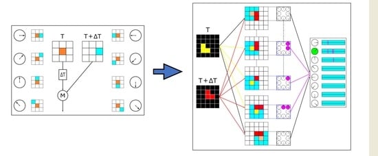
Figure 3 shows the detection process of the AVS for a 1-pixel object. We use notations , , , …, to indicate the positions of photoreceptors in the visual field, so the detection process in Figure 3 can be described as follows. Firstly, the light spot at time T (yellow dot) is received by the centrally located photoreceptor of the 5 × 5 visual field. Secondly, the outputs of each photoreceptor are sent to 8 local motion-sensitive directionally detective neurons, which will be delayed until time T + ∆T, and received by the center point of each local motion-sensitive directionally detective neuron’s 3 × 3 local receptive field. Thirdly, each local motion-sensitive directionally detective neuron will detect whether there exists a signal from the photoreceptor located in its preferred direction at time T + ∆T (orange dot center, blue dots surrounding it). In this flowchart, the photoreceptor located at receives the light signal at time T, and receives the signal at time T + ∆T (red dot), so the 0°-detective neuron is activated (pink dot). Finally, the AVS gives the detection result based on the maximum value of activation strength in eight directions. Since the 0°-detective neuron located at is the only activated neuron during this detection, the global motion direction of this 1-pixel object is rightward. A more complex process of the AVS for a 3-pixel object is presented in Figure 4. During this detection, a total of 5 local motion-sensitive directionally detective neurons have been activated. They are 0°-detective neuron and 45°-detective neuron located at , 45°-detective neuron located at , 45°-detective neuron, and 90°-detective neuron located at . As the 45°-detective neurons achieve the maximum value of the activation strength, the global motion direction of this 3-pixel object is upper rightward.
3. Results and Discussion
To validate the reliability of our AVS, we conduct a series of experiments with a background size of 32 × 32, 1,024-pixel datasets. The objects in all experiments have random sizes ranging from 1 to 128 pixels, and their shapes and positions are set to arbitrary.
In the first series of experiments, we test our AVS within the background with no noise. The dataset has a total of 192,000 images (each object has 24,000 images), and the detection results are presented in Table 1. The activation plots of the AVS for a 16-pixel object motion direction detection within the background with no noise are shown in Figure 5. The activation numbers of eight local motion-sensitive directionally detective neurons are: 0°-detective neurons 5, 45°-detective neurons 5, 90°-detective neurons 9, 135°-detective neurons 16, 180°-detective neurons 8, 225°-detective neurons 7, 270°-detective neurons 6, and 315°-detective neurons 5. Thus, the global direction of this 16-pixel object’s motion is upper leftward.
In the second series of experiments, we test our AVS within the background with 1% to 10% separated noises. The dataset has a total of 192,000 images (each object has 24,000 images), and the detection results are presented in Table 2. The reason why the separated noises have no effect on the detection results is because the noise remains stationary between the time T and the time T + ∆T. Therefore, no local motion-sensitive directionally detective neurons have been activated by the noises. Figure 6 shows an example of the activation plots of the AVS for a 32-pixel object motion direction detection within the background with 10% separated noises. The activation numbers of eight local motion-sensitive directionally detective neurons are: 0°-detective neurons 17, 45°-detective neurons 14, 90°-detective neurons 15, 135°-detective neurons 14, 180°-detective neurons 15, 225°-detective neurons 18, 270°-detective neurons 32, and 315°-detective neurons 18. Thus, the global direction of this 32-pixel object’s motion is downward.
In the third series of experiments, we test our AVS within the background with 1% to 10% connected noises. The dataset has a total of 192,000 images (each object has 24,000 images), and the detection results are presented in Table 3. Through observation, it can be found that the connected noises do have impacts on the detection results, especially when the object’s size is small. However, as the size of the object increases, the detection results will return to high accuracy. The activation plots of the AVS for a 64-pixel object motion direction detection within the background with 2% connected noises have been presented in Figure 7, and the error activations due to noise are represented by the purple dots. The activation numbers of eight local motion-sensitive directionally detective neurons are: 0°-detective neurons 33, 45°-detective neurons 31, 90°-detective neurons 35, 135°-detective neurons 38, 180°-detective neurons 43, 225°-detective neurons 64, 270°-detective neurons 41, and 315°-detective neurons 34. Thus, the global direction of this 64-pixel object’s motion is Lower Leftward.
In the last series of experiments, we compare the performance of the AVS, the time-considered CNN, and the EfficientNetB0. In recent research, convolutional architectures performed well in tasking audio synthesis, and convolutional networks are regarded as the natural starting point for sequence modeling tasks [58]. Therefore, we propose a time-considered CNN train it for the task of detecting the global direction of motion. The time-considered CNN is made up of eight convolution kernels (3 × 3), eight feature maps (32 × 32), and eight outputs. The structure of the time-considered CNN is shown in Figure 8. At first, we used the dataset with no noise in the background and randomly picked 3000 images out of 24,000 images from each size of the object’s dataset to form a new dataset. Then, we picked 15,000 images in the new dataset for training the CNN and the EfficientNetB0 and then used 5000 of the remaining images to form the test dataset. Finally, we saved the CNN and the EfficientNetB0 when the training accuracy reached 100% and compared their performances with the proposed AVS. The accuracy rates on the test dataset are: AVS 100%, the time-considered CNN 63.6%, and the EfficientNetB0 100%. Furthermore, we performed a comparison of the three models in detecting the dataset with separated noises and the dataset with connected noises. These detection results are shown in Table 4, Table 5, Table 6 and Table 7, respectively. We can easily observe from these tables that our AVS has better performance than the time-considered CNN and the EfficientNetB0. Furthermore, since our AVS cites the spatial structure of the basic form of the HRC model, the requirements on the dataset are almost none, while the CNN and the EfficientNetB0 need a large amount of data for training.
4. Conclusions
In this paper, we proposed an artificial visual system using the full-neurons scheme motion direction detection mechanism to detect the global direction of motion. With reference to the ON-edge motion pathway in flies, we assumed that each light spot in the visual field can be received by eight local motion-sensitive directionally detective neurons. The detection in each local motion-sensitive directionally detective neuron is based on the core computation of the HRC model, and the global motion direction is inferred from the maximum value of activation strength in eight directions. Through three different types of experiments, we demonstrated that the proposed AVS not only has a great motion direction detection ability, but also has good resistance to noises. Additionally, through comparison of our AVS with the time-considered CNN and the EfficientNetB0, we verified the possibility of the proposed AVS as an engineering application. Although our AVS is still in the early stages of design, it already exhibits three notable advantages: learning costs, noise resistance, and structural extensibility. With the application of neurons with different functions in our designed AVS, the AVS can be used for more complex detection tasks. For example, in subsequent experiments, we initially confirmed that the application of the horizontal cells concept will allow our AVS to detect the direction of motion in grayscale images. We will continue to explore our artificial visual system in conjunction with investigations from biological research.
Author Contributions
Conceptualization, Y.T. and Z.T.; methodology, Y.T. and Z.T.; software, C.Y., Y.K. and B.L.; formal analysis, Y.T., Z.T. and C.Y.; writing—original draft preparation, C.Y.; writing—review and editing, Y.K., Z.T. and C.Y. All authors have read and agreed to the published version of the manuscript.
Funding
This work was funded by JSPS KAKENHI Grant No.19K12136.
Data Availability Statement
The datasets used and/or analyzed during the current study are available from the corresponding author on reasonable request.
Conflicts of Interest
The authors declare no conflict of interest.
References
- Fiske, S.T.; Taylor, S.E. Social Cognition; Mcgraw-Hill Book Company: New York, NY, USA, 1991. [Google Scholar]
- Livingstone, M.S. Art, illusion and the visual system. Sci. Am. 1988, 258, 78–85. [Google Scholar] [CrossRef] [PubMed]
- Livingstone, M.; Hubel, D. Segregation of form, color, movement, and depth: Anatomy, physiology, and perception. Science 1988, 240, 740–749. [Google Scholar] [CrossRef] [PubMed] [Green Version]
- Zhang, S.; Srinivasan, M.V. Behavioural evidence for parallel information processing in the visual system of insects. Jpn. J. Physiol. 1993, 43, 247–258. [Google Scholar]
- Nakayama, K. Biological image motion processing: A review. Vis. Res. 1985, 25, 625–660. [Google Scholar] [CrossRef]
- Exner, S. Entwurf zu einer Physiologischen Erklärung der Psychischen Erscheinungen; Deuticke: Leipzig, Germany, 1894. [Google Scholar]
- Wertheimer, M. Experimentelle studien uber das sehen von bewegung. In Zeitschrift fur Psychologie; Verlag von Johann Ambrosius Barth: Leipzig, Germany, 1912; p. 61. [Google Scholar]
- Adrian, E.D.; Matthews, R. The action of light on the eye: Part I. The discharge of impulses in the optic nerve and its relation to the electric changes in the retina. J. Physiol. 1927, 63, 378–414. [Google Scholar] [CrossRef] [Green Version]
- Adrian, E.D.; Matthews, R. The action of light on the eye: Part II. The processes involved in retinal excitation. J. Physiol. 1927, 64, 279–301. [Google Scholar] [CrossRef] [PubMed] [Green Version]
- Adrian, E.D.; Matthews, R. The action of light on the eye: Part III. The interaction of retinal neurones. J. Physiol. 1928, 65, 273–298. [Google Scholar] [CrossRef]
- Hartline, H.K.; Graham, C.H. Nerve impulses from single receptors in the eye. J. Cell. Comp. Physiol. 1932, 1, 277. [Google Scholar] [CrossRef]
- Hartline, H.K. The response of single optic nerve fibers of the vertebrate eye to illumination of the retina. Am. J. Physiol.-Leg. Content 1938, 121, 400–415. [Google Scholar] [CrossRef]
- Kuffler, S.W. Discharge patterns and functional organization of mammalian retina. J. Neurophysiol. 1953, 16, 37–68. [Google Scholar] [CrossRef] [Green Version]
- Barlow, H.B.; Levick, W.R. The mechanism of directionally selective units in rabbit’s retina. J. Physiol. 1965, 178, 477. [Google Scholar] [CrossRef] [PubMed] [Green Version]
- Hausen, K. The lobula-complex of the fly: Structure, function and significance in visual behaviour. In Photoreception and Vision in Invertebrates; Springer: Boston, MA, USA, 1984; pp. 523–559. [Google Scholar]
- Hassenstein, B.; Reichardt, W. Systemtheoretische analyse der zeit-, reihenfolgen-und vorzeichenauswertung bei der bewegungsperzeption des rüsselkäfers chlorophanus. Z. Nat. B 1956, 11, 513–524. [Google Scholar] [CrossRef] [Green Version]
- Reichardt, W. Autocorrelation, a principle for evaluation of sensory information by the central nervous system. In Proceedings of the Symposium on Principles of Sensory Communication, New York, NY, USA, 1 January 1961; pp. 303–317. [Google Scholar]
- Van Santen, J.P.H.; Sperling, G. Elaborated reichardt detectors. JOSA A 1985, 2, 300–321. [Google Scholar] [CrossRef] [PubMed]
- Hildreth, E.C.; Koch, C. The analysis of visual motion: From computational theory to neuronal mechanisms. Ann. Rev. Neurosci. 1987, 10, 477–533. [Google Scholar] [CrossRef] [PubMed]
- Reichardt, W. Evaluation of optical motion information by movement detectors. J. Comp. Physiol. A 1987, 161, 533–547. [Google Scholar] [CrossRef]
- Borst, A.; Egelhaaf, M. Principles of visual motion detection. Trends Neurosci. 1989, 12, 297–306. [Google Scholar] [CrossRef] [Green Version]
- Beauchemin, S.S.; Barron, J.L. The computation of optical flow. ACM Comput. Surv. 1995, 27, 433–466. [Google Scholar] [CrossRef]
- Clifford, C.W.G.; Ibbotson, M.R. Fundamental mechanisms of visual motion detection: Models, cells and functions. Prog. Neurobiol. 2002, 68, 409–437. [Google Scholar] [CrossRef]
- Borst, A.; Euler, T. Seeing things in motion: Models, circuits, and mechanisms. Neuron 2011, 71, 974–994. [Google Scholar] [CrossRef] [Green Version]
- Rister, J.; Pauls, D.; Schnell, B.; Ting, C.Y.; Lee, C.H.; Sinakevitch, I.; Morante, J.; Strausfeld, N.J.; Ito, K.; Heisenberg, M. Dissection of the peripheral motion channel in the visual system of Drosophila melanogaster. Neuron 2007, 56, 155–170. [Google Scholar] [CrossRef] [Green Version]
- Takemura, S.Y.; Lu, Z.; Meinertzhagen, I.A. Synaptic circuits of the Drosophila optic lobe: The input terminals to the medulla. J. Comp. Neurol. 2008, 509, 493–513. [Google Scholar] [CrossRef] [PubMed] [Green Version]
- Joesch, M.; Plett, J.; Borst, A.; Reiff, D.F. Response properties of motion-sensitive visual interneurons in the lobula plate of Drosophila melanogaster. Curr. Biol. 2008, 18, 368–374. [Google Scholar] [CrossRef] [PubMed] [Green Version]
- Sanes, J.R.; Zipursky, S.L. Design principles of insect and vertebrate visual systems. Neuron 2010, 66, 15–36. [Google Scholar] [CrossRef] [PubMed] [Green Version]
- Borst, A.; Haag, J.; Reiff, D.F. Fly motion vision. Ann. Rev. Neurosci. 2010, 33, 49–70. [Google Scholar] [CrossRef]
- Briggman, K.L.; Helmstaedter, M.; Denk, W. Wiring specificity in the direction-selectivity circuit of the retina. Nature 2011, 471, 183–188. [Google Scholar] [CrossRef]
- Takemura, S.Y.; Bharioke, A.; Lu, Z.; Nern, A.; Vitaladevuni, S.; Rivlin, P.K.; Katz, W.T.; Olbris, D.J.; Plaza, S.M.; Winston, P.; et al. A visual motion detection circuit suggested by Drosophila connectomics. Nature 2013, 500, 175–181. [Google Scholar] [CrossRef] [Green Version]
- Borst, A.; Helmstaedter, M. Common circuit design in fly and mammalian motion vision. Nat. Neurosci. 2015, 18, 1067–1076. [Google Scholar] [CrossRef]
- Takemura, S.Y.; Nern, A.; Chklovskii, D.B.; Scheffer, L.K.; Rubin, G.M.; Meinertzhagen, I.A. The comprehensive connectome of a neural substrate for ‘ON’motion detection in Drosophila. Elife 2017, 6, e24394. [Google Scholar] [CrossRef] [Green Version]
- Strother, J.A.; Wu, S.T.; Wong, A.M.; Nern, A.; Rogers, E.M.; Le, J.Q.; Rubin, G.M.; Reiser, M.B. The emergence of directional selectivity in the visual motion pathway of Drosophila. Neuron 2017, 94, 168–182. [Google Scholar] [CrossRef] [Green Version]
- Shinomiya, K.; Huang, G.; Lu, Z.; Parag, T.; Xu, C.S.; Aniceto, R.; Ansari, N.; Cheatham, N.; Lauchie, S.; Neace, E.; et al. Comparisons between the ON-and OFF-edge motion pathways in the Drosophila brain. Elife 2019, 8, e40025. [Google Scholar] [CrossRef]
- Groschner, L.N.; Malis, J.G.; Zuidinga, B.; Borst, A. A biophysical account of multiplication by a single neuron. Nature 2022, 603, 119–123. [Google Scholar] [CrossRef] [PubMed]
- Mauss, A.S.; Vlasits, A.; Borst, A.; Feller, M. Visual circuits for direction selectivity. Ann. Rev. Neurosci. 2017, 40, 211–230. [Google Scholar] [CrossRef] [PubMed]
- Fukushima, K.; Miyake, S. Neocognitron: A self-organizing neural network model for a mechanism of visual pattern recognition. In Competition and Cooperation in Neural Nets; Springer: Berlin/Heidelberg, Germany, 1982; pp. 267–285. [Google Scholar]
- Adelson, E.H.; Bergen, J.R. Spatiotemporal energy models for the perception of motion. J. Opt. Soc. Am. A 1985, 2, 284–299. [Google Scholar] [CrossRef] [PubMed] [Green Version]
- Hubel, D.H.; Wiesel, T.N. Receptive fields and functional architecture of monkey striate cortex. J. Physiol. 1968, 195, 215–243. [Google Scholar] [CrossRef]
- Tang, C.; Todo, Y.; Ji, J.; Tang, Z. A novel motion direction detection mechanism based on dendritic computation of direction-selective ganglion cells. Knowl.-Based Syst. 2022, 241, 108205. [Google Scholar] [CrossRef]
- Han, M.; Todo, Y.; Tang, Z. Mechanism of Motion Direction Detection Based on Barlow’s Retina Inhibitory Scheme in Direction-Selective Ganglion Cells. Electronics 2021, 10, 1663. [Google Scholar] [CrossRef]
- Yan, C.; Todo, Y.; Tang, Z. The Mechanism of Motion Direction Detection Based on Hassenstein-Reichardt Model. In Proceedings of the 2021 6th International Conference on Computational Intelligence and Applications (ICCIA), Xiamen, China, 11–13 June 2021; pp. 180–184. [Google Scholar]
- Kobayashi, Y.; Todo, Y.; Tang, Z. Mechanism and Learning of Motion Direction Detection Using Dendritic Neuron Model based Direction Selective Ganglion Cells. In Proceedings of the 22nd International Conference on Bioinformatics & Computational Biology (BIOCOMP’21), Las Vegas, NV, USA, 26–29 July 2021. [Google Scholar]
- Zhang, X.; Todo, Y.; Tang, C.; Tang, Z. The Mechanism of Orientation Detection Based on Dendritic Neuron. In Proceedings of the 2021 IEEE 4th International Conference on Big Data and Artificial Intelligence (BDAI), Qingdao, China, 2–4 July 2021; pp. 225–229. [Google Scholar]
- Li, B.; Todo, Y.; Tang, Z. The Mechanism of Orientation Detection Based on Local Orientation-Selective Neuron. In Proceedings of the 2021 6th International Conference on Computational Intelligence and Applications (ICCIA), Xiamen, China, 11–13 June 2021; pp. 195–199. [Google Scholar]
- Joesch, M.; Schnell, B.; Raghu, S.V.; Raghu, S.V.; Reiff, D.F.; Borst, A. ON and OFF pathways in Drosophila motion vision. Nature 2010, 468, 300–304. [Google Scholar] [CrossRef]
- Behnia, R.; Clark, D.A.; Carter, A.G.; Clandinin, T.R.; Desplan, C. Processing properties of ON and OFF pathways for Drosophila motion detection. Nature 2014, 512, 427–430. [Google Scholar] [CrossRef]
- Yue, S.; Fu, Q. Modeling direction selective visual neural network with on and off pathways for extracting motion cues from cluttered background. In Proceedings of the 2017 International Joint Conference on Neural Networks (IJCNN), Anchorage, AK, USA, 14–19 May 2017; pp. 831–838. [Google Scholar]
- Fu, Q.; Yue, S. Modelling Drosophila motion vision pathways for decoding the direction of translating objects against cluttered moving backgrounds. Biol. Cybern. 2020, 114, 443–460. [Google Scholar] [CrossRef]
- Borst, A.; Haag, J.; Mauss, A.S. How fly neurons compute the direction of visual motion. J. Comp. Physiol. A 2020, 206, 109–124. [Google Scholar] [CrossRef] [Green Version]
- Frye, M. Elementary motion detectors. Curr. Biol. 2015, 25, 215–217. [Google Scholar] [CrossRef] [PubMed] [Green Version]
- Maisak, M.S.; Haag, J.; Ammer, G.; Serbe, E.; Meier, M.; Leonhardt, A.; Schilling, T.; Bahl, A.; Rubin, G.M.; Nern, A.; et al. A directional tuning map of Drosophila elementary motion detectors. Nature 2013, 500, 212–216. [Google Scholar] [CrossRef] [PubMed]
- Mauss, A.S.; Pankova, K.; Arenz, A.; Nern, A.; Rubin, G.M.; Borst, A. Neural circuit to integrate opposing motions in the visual field. Cell 2015, 162, 351–362. [Google Scholar] [CrossRef] [PubMed] [Green Version]
- Zavatone-Veth, J.A.; Badwan, B.A.; Clark, D.A. A minimal synaptic model for direction selective neurons in Drosophila. J. Vis. 2020, 20, 2. [Google Scholar] [CrossRef] [Green Version]
- Davis, F.P.; Nern, A.; Picard, S.; Reiser, M.B.; Rubin, G.M.; Eddy, S.R.; Henry, G.L. A genetic, genomic, and computational resource for exploring neural circuit function. eLife 2020, 9, 50901. [Google Scholar] [CrossRef]
- Özel, M.N.; Simon, F.; Jafari, S.; Holguera, I.; Chen, Y.C.; Benhra, N.; EI-Danaf, R.J.; Kapuralin, K.; Malin, J.A.; Konstantinides, N.; et al. Neuronal diversity and convergence in a visual system developmental atlas. Nature 2021, 589, 88–95. [Google Scholar] [CrossRef]
- Bai, S.; Kolter, J.Z.; Koltun, V. An empirical evaluation of generic convolutional and recurrent networks for sequence modeling. arXiv 2018, arXiv:1803.01271. [Google Scholar]
Figure 1.
(a) Schematic of the HRC model. (b) Schematic of the rightwards motion detector of the HRC model. (c) Process of the rightward motion detector in detecting its preferred direction (left) and null direction (right). In its preferred direction, the activation signal caused by the light spot at time T (yellow) will be delayed until time T + ∆T and then multiply with the activation signal caused by the light spot at time T + ∆T (red); thus, the rightward motion detector will respond (pink). Conversely, the rightwards motion detector will evoke no response in its null direction detection because the signal from the receptor at time T has not been temporally delayed.

Figure 2.
(a) The theoretical structure of the rightwards local motion-sensitive directionally detective neuron. (b) Schematic of 0°-detective neuron. The rightwards local motion-sensitive directionally detective neuron will respond when both the photoreceptor at time T and the photoreceptor at time T + ∆T. (c) Schematic of eight local motion-sensitive directionally detective neurons.

Figure 3.
Flowchart of the AVS in detecting 1-pixel object.

Figure 4.
Flowchart of the AVS in detecting 3-pixel object.

Figure 5.
The activation plots of the AVS for 16-pixel object motion direction detection within the background with no noise.
Figure 5.
The activation plots of the AVS for 16-pixel object motion direction detection within the background with no noise.

Figure 6.
The activation plots of the AVS for 32-pixel object motion direction detection within the background with 10% separated noises.
Figure 6.
The activation plots of the AVS for 32-pixel object motion direction detection within the background with 10% separated noises.

Figure 7.
The activation plots of the AVS for 64-pixel object motion direction detection within the background with 2% connected noises.
Figure 7.
The activation plots of the AVS for 64-pixel object motion direction detection within the background with 2% connected noises.

Figure 8.
Schematic of the time-considered CNN.


Table 1.
Detection results of the AVS within the background with no noise.
| Model | 1 | 2 | 4 | 8 | 16 | 32 | 64 | 128 |
|---|---|---|---|---|---|---|---|---|
| AVS | 100% | 100% | 100% | 100% | 100% | 100% | 100% | 100% |
Table 2.
Detection results of the AVS within the background with separated noises.
| Noises | 1 | 2 | 4 | 8 | 16 | 32 | 64 | 128 |
|---|---|---|---|---|---|---|---|---|
| 1% | 100% | 100% | 100% | 100% | 100% | 100% | 100% | 100% |
| 2% | 100% | 100% | 100% | 100% | 100% | 100% | 100% | 100% |
| 5% | 100% | 100% | 100% | 100% | 100% | 100% | 100% | 100% |
| 10% | 100% | 100% | 100% | 100% | 100% | 100% | 100% | 100% |
Table 3.
Detection results of the AVS within the background with connected noises.
| Noises | 1 | 2 | 4 | 8 | 16 | 32 | 64 | 128 |
|---|---|---|---|---|---|---|---|---|
| 1% | 81.6% | 96.0% | 99.8% | 100% | 100% | 100% | 100% | 100% |
| 2% | 56.7% | 84.0% | 97.9% | 99.9% | 100% | 100% | 100% | 100% |
| 5% | 36.6% | 52.1% | 75.0% | 95.1% | 99.8% | 100% | 100% | 100% |
| 10% | 30.7% | 37.8% | 52.3% | 74.1% | 94.5% | 99.8% | 100% | 100% |
Table 4.
Detection results of the time-considered CNN within the background with separated noises.
| Noises | 1 | 2 | 4 | 8 | 16 | 32 | 64 | 128 |
|---|---|---|---|---|---|---|---|---|
| 1% | 14.8% | 19.7% | 20.0% | 25.4% | 36.0% | 55.6% | 78.6% | 95.0% |
| 2% | 13.8% | 14.7% | 16.1% | 18.4% | 23.9% | 36.7% | 58.2% | 86.9% |
| 5% | 12.9% | 13.5% | 13.7% | 14.4% | 16.9% | 21.3% | 28.2% | 55.8% |
| 10% | 12.7% | 12.9% | 13.3% | 13.5% | 15.6% | 18.6% | 21.1% | 37.8% |
Table 5.
Detection results of the time-considered CNN within the background with connected noises.
| Noises | 1 | 2 | 4 | 8 | 16 | 32 | 64 | 128 |
|---|---|---|---|---|---|---|---|---|
| 1% | 15.2% | 17.4% | 20.3% | 25.7% | 36.4% | 55.9% | 79.9% | 95.1% |
| 2% | 13.6% | 14.7% | 15.8% | 18.8% | 23.9% | 37.2% | 62.1% | 88.9% |
| 5% | 12.9% | 13.4% | 14.1% | 15.0% | 16.5% | 20.8% | 33.8% | 65.7% |
| 10% | 12.7% | 13.0% | 13.4% | 13.9% | 15.3% | 17.9% | 25.3% | 50.6% |
Table 6.
Detection results of the EfficientNetB0 within the background with separated noises.
| Noises | 1 | 2 | 4 | 8 | 16 | 32 | 64 | 128 |
|---|---|---|---|---|---|---|---|---|
| 1% | 29.3% | 36.9% | 43.8% | 50.1% | 58.4% | 64.8% | 69.9% | 81.5% |
| 2% | 15.0% | 18.4% | 22.1% | 28.4% | 37.2% | 43.9% | 52.2% | 66.8% |
| 5% | 14.0% | 14.5% | 15.7% | 17.2% | 22.6% | 29.8% | 42.2% | 58.0% |
| 10% | 12.9% | 11.9% | 12.1% | 12.7% | 15.2% | 18.9% | 23.6% | 30.5% |
Table 7.
Detection results of the EfficientNetB0 within the background with connected noises.
| Noises | 1 | 2 | 4 | 8 | 16 | 32 | 64 | 128 |
|---|---|---|---|---|---|---|---|---|
| 1% | 27.8% | 34.2% | 43.0% | 51.2% | 58.6% | 63.1% | 72.5% | 82.8% |
| 2% | 15.4% | 18.2% | 22.2% | 30.8% | 36.0% | 42.7% | 52.4% | 66.1% |
| 5% | 13.8% | 14.1% | 13.4% | 16.9% | 20.4% | 28.2% | 38.8% | 55.4% |
| 10% | 13.3% | 13.0% | 14.1% | 17.4% | 20.3% | 26.4% | 33.0% | 39.9% |
Publisher’s Note: MDPI stays neutral with regard to jurisdictional claims in published maps and institutional affiliations. |
© 2022 by the authors. Licensee MDPI, Basel, Switzerland. This article is an open access article distributed under the terms and conditions of the Creative Commons Attribution (CC BY) license (https://creativecommons.org/licenses/by/4.0/).
Share and Cite
MDPI and ACS Style
Yan, C.; Todo, Y.; Kobayashi, Y.; Tang, Z.; Li, B. An Artificial Visual System for Motion Direction Detection Based on the Hassenstein–Reichardt Correlator Model. Electronics 2022, 11, 1423. https://doi.org/10.3390/electronics11091423
AMA Style
Yan C, Todo Y, Kobayashi Y, Tang Z, Li B. An Artificial Visual System for Motion Direction Detection Based on the Hassenstein–Reichardt Correlator Model. Electronics. 2022; 11(9):1423. https://doi.org/10.3390/electronics11091423
Chicago/Turabian StyleYan, Chenyang, Yuki Todo, Yuki Kobayashi, Zheng Tang, and Bin Li. 2022. "An Artificial Visual System for Motion Direction Detection Based on the Hassenstein–Reichardt Correlator Model" Electronics 11, no. 9: 1423. https://doi.org/10.3390/electronics11091423
Note that from the first issue of 2016, this journal uses article numbers instead of page numbers. See further details here.