
A Compact Fourth-Order Tunable Bandpass Filter Based on Varactor-Loaded Step-Impedance Resonators
Xi’an Institute of Space Radio Technology, Xi’an 710100, China
*
Author to whom correspondence should be addressed.
Electronics 2023, 12(11), 2539; https://doi.org/10.3390/electronics12112539
Submission received: 17 May 2023
/
Revised: 30 May 2023
/
Accepted: 2 June 2023
/
Published: 5 June 2023
(This article belongs to the Special Issue Microwave Devices: Analysis, Design, and Application)
Abstract
:In this paper, a compact high-selectivity frequency tunable bandpass filter (BPF) with constant absolute bandwidth (ABW) based on varactor-loaded step-impedance resonators (SIRs) is presented. By introducing cross coupling between resonators, a pair of transmission zeros (TZs) close to the passband are produced and the selectivity of the filter is enhanced significantly. Another pair of TZs are generated to improve the out-of-band rejection by using source-load coupling. The varactor-loaded SIRs are utilized to design the compact fourth-order tunable BPF in order to realize wide tuning range and compact size. In addition, the frequency-dependent coupling feeding structures are employed instead of lumped capacitors used in conventional feeding structures, as a result, the insertion-loss performance is improved. The simulated and measured results are presented and show good agreement. The measured results exhibit a tuning range from 0.8 to 1.14 GHz with a 3 dB constant ABW of about 47 ± 5 MHz, the return loss of the filter is greater than 13.9 dB, and the insertion loss is about 2.7–3.1 dB. Moreover, four TZs are generated, and the proposed tunable filter shows high selectivity with a rectangular coefficient of 2.3–3.1.
1. Introduction
With the development of modern wireless communication systems, more frequency bands are utilized, and RF front-ends need to operate at multiple frequency bands [1]. The traditional RF front-end solution termed filter bank to achieve multi-band compatibility generally occupy large area on circuit board and have high costs [2].The electrically tunable filter which can support numerous frequency bands with a single filter structure may meet the requirements of miniaturization, integration and low cost, is one of the promising microwave components for future wireless communications [3].
Recently, numbers of electrically tunable bandpass filters have been proposed. Two-pole tunable bandpass filters based on uniform-impedance resonators (UIRs) are introduced in [4,5]. Two tunable transmission zeros are generated due to the source-load coupling architecture. In [6,7], two-pole frequency tunable filters based on mixed coupling structures are proposed, by adjusting the mixed coupling structures, the constant bandwidth characteristic is achieved. In addition to these tunable filters based on coupled resonators, dual-mode resonators are also used to design frequency tunable filters in [8] and [9]. In [10], a frequency tunable bandpass filter based on coupled line is proposed, the proposed tunable filter has a simple structure and wide tuning range. However, these aforementioned low-order tunable filters (with two poles) usually suffer from poor selectivity. In order to improve the selectivity of filters, several high-order tunable filters are presented in [11,12,13,14,15,16]. In [11], a miniature tunable four-pole bandpass filter is demonstrated, the selectivity of the proposed filters is improved significantly compared with two-pole filters. Nevertheless, the absolute bandwidth of the filter cannot remain constant throughout the tuning range. In [12], defected ground structures (DGSs) are applied in the coupling schemes of the presented planar tunable filter to achieve constant ABW, while the selectivity of the filter is inadequate. In [13], a cross-coupled tunable bandpass filter based on full-wavelength tunable resonators is proposed. The proposed tunable filter is comprised of two cascaded-trisection structures, and two transmission zeros are generated for improving the frequency selectivity; however, the structure of the proposed filter is complicated, and the insertion loss is large. In [14,15,16], fourth-order tunable filters with constant ABW are demonstrated; however, in order to maintain constant ABW, lumped capacitors are used to connect the feeding microstrip lines to the filter, which may increase the insertion loss of the tunable filters. In [17,18], fourth-order tunable BPFs with high selectivity are designed. The proposed tunable BPFs are manufactured by low temperature co-fired ceramic (LTCC) technology, as a result, the integration of the filters is enhanced, and the filters are compact, but the tuning range of the filters is not good. In [19], an electrical tunable microstrip bandpass filter with cross coupling is proposed. The proposed tunable BPF cannot maintain constant ABW during the tuning range. In [20], a tunable fourth-order BPF with constant ABW is presented. The filter is based on varactor-loaded UIRs, and the selectivity of the proposed filter is enhanced significantly due to the cross-coupling structures; however, the tuning range of the filter also need to be improved. Thus, it is still a challenge to design a compact fourth-order tunable filter with high selectivity, wide tuning range and constant ABW.
In this paper, a compact frequency tunable bandpass filter with high selectivity, wide tuning range and constant ABW based on varactor-loaded SIRs is proposed. The proposed tunable filter is comprised of four varactor-loaded SIRs. To enhance selectivity of the filter, the cascaded quadruplet (CQ) filter topology is utilized, and two transmission zeros located close to the passband are generated. Meanwhile, cross coupling between the input and output feeding microstrip lines is introduced to generate two additional transmission zeros. By regulating the ratio between electric coupling and magnetic coupling and making the overall coupling coefficient inversely proportional to frequency, constant ABW of the proposed filter is realized. In addition, the proposed tunable filter is compact as a result of the application of the varactor-loaded SIR. The insertion loss of the proposed tunable BPF is improved due to the application of the frequency-dependent coupling-feeding structures.
2. Theory of Tunable BPF with Constant ABW
According to the classical filter synthesis theory, transmission zeros at finite frequencies can be generated by introducing cross coupling between resonators [21], and the selectivity of bandpass filter can be improved effectively by arranging the location of the transmission zeros properly. In this paper, the typical CQ filter topology is employed to enhance the selectivity of the tunable filter. In addition, the source-load coupling is introduced to produce additional two transmission zeros. Figure 1 illustrates the topology of the proposed filter. Each green node represents a resonator, the resonant frequencies of resonators are electronically controlled by varactor diodes. The S and L node represent the source and load of the tunable filter. The solid lines indicate the main path couplings, and the dashed line denotes the cross couplings. E and M represent electric and magnetic coupling, respectively.
The general normalized coupling matrix denoted by [m] is employed to represent the proposed tunable filter topology. The coupling coefficient between the resonator i and j (i, j = 1, 2, 3, 4) is denoted by mij, mS1 represents the input couplings between the source, and resonator 1, m4L represents the output coupling between the load and resonator 4, and mSL represents the input couplings between the source and load. For the sake of simplicity, the diagonal entries of the general coupling matrix are all zeros assuming all resonators resonating at the same frequency here. In addition, m13 and m24 are also zeros, which indicates that the coupling between the nonadjacent resonators is zero, with the exception of the cross coupling between resonators 1 and 4.
then the normalized coupling matrix [m] can be mapped to the center frequency fc and scaled by fractional bandwidth (FBW). Thus, the denormalized coupling matrix [M] can be obtained from the following equation:
QeS and QeL are the external quality factors in association with the input and output couplings, respectively. QeS and QeL can be expressed as follows:
for frequency tunable filters with constant ABW. In order to make filer response of the tunable filter remain stable, the normalized coupling matrix [m] of the filer should remain unchanged [22]. Thus, from Equations (1)–(3), it can be shown that the coupling coefficient Mij between resonators is inversely proportional to the frequency, and the external quality factor QeS and QeL is directly proportional to the frequency.
In order to illustrate the synthesis procedure for frequency tunable filter with constant ABW, a design example of a fourth-order tunable filter is demonstrated here. For a frequency tunable filter with ABW 50 MHz, the tuning range is 0.8~1.1 GHz, maximum in-band return loss of the filter is 20 dB. To enhance the selectivity and stopband performance of the filter, two pairs of transmission zeros at the normalized resonant frequency ±1.7 and ±25 are designed. Based on the method introduced in [23], the normalized coupling matrix [m] can be obtained using the predefined return loss and transmission zero distribution. The matrix [m] is expressed as follows:
The de-normalized coupling matrix and external quality can be obtained by Equations (1)–(3). Thus, the M12, M23, M14 and Qe can be expressed as shown in Figure 2. Because of the symmetric distribution of the filter, M34 = M12, Qe = QeS = QeL.
Based on the coupling matrix [M] and external quality Qe calculated before, the filter response S11 and S12 can be obtained by Equations (5)–(7).
where [U] is similar to the (n + 2) × (n + 2) identity matrix, except that [U]11 = [U]n + 2, n + 2 = 0, [q] is the (n + 2) × (n + 2) matrix with all entries zeros, except for [q]11 = [q] n + 2,n + 2 =1.
The filter response of the tunable filter is shown in Figure 3. It can be seen that during the whole tuning range, and the S11 and S12 curves remain stable, the absolute bandwidth remains 50 MHz, two transmission zeros close to the passband are generated, and the selectivity of the proposed filter is improved significantly, besides, another two transmission zeros located far from the passband are also produced, and this two transmission zeros are very useful to enhance the rejection level of stopband.
3. Analysis of the Varactor-Loaded SIR
In compared to conventional UIR, filters based on SIRs usually have a smaller size and superior stopband performance. Therefore, varactor-loaded SIR is employed to design tunable filters. Figure 4 shows the layout of the proposed varactor-loaded SIR, the SIR consists of two transmission lines, whose electrical length and characteristic admittance are θ1, θ2 and Y1, Y2, respectively. The varactor diode is loaded at the position θc away from the short end of the SIR. Cv is the effective capacitance of varactor diode.
Based on transmission line theory in [23], the following equations can be used to estimate the input admittance Yin.
The resonance condition that the imaginary part of the input admittance must be zero is shown by Equation (11). Thus Equations (8)–(11) can be used to calculate the resonance frequency of tunable SIR.
To investigate the impact of locating position θc on resonance characteristics of the proposed tunable SIR, the following analysis is conducted. Figure 5 shows resonance frequency versus the capacitance Cv of varactor diode with different values of locating position θc. As the capacitance Cv increases, the resonance frequency of the proposed SIR decreases. However, for the same Cv, the resonance frequency will not change significantly with different values of loading position θc.
Tuning range (TR) is important for frequency tunable bandpass filters, which can be defined as Equation (12). In (12), f(Cv_min) and f(Cv_max) represent the resonance frequency of the SIR when the efficient capacitance Cv is the minimum and maximum value, respectively.
Equation (13) defines the electrical length ratio α of the proposed tunable SIR, and Equation (14) defines the characteristic admittance ratio β of the proposed tunable SIR. It can be seen that the resonance characteristic can be affected by α and β from Equations (8)–(11).
for specific electrical length ratio α and characteristic admittance ratio β, Y2, θ1 and θ2 as marked in Figure 4. These values can be calculated by Equations (13) and (14) when assuming that θ1 + θ2 = 180° and Y1 = 0.03 S. Then, resonance frequency of the proposed step-impedance resonator can be calculated by Equations (8)–(11). Finally, the tuning range can be obtained by Equation (12), here, Cv_min = 1.77pf Cv_max = 9.24 pf (SMV1413).
The relationships between TR and α under different values of β is shown in Figure 6. If β is chosen to be 1, the proposed tunable resonator will become a UIR, and the TR will remain unchanged when α varies. In addition, it can be seen that the TR will be widened when β increases, which means that the varactor-loaded SIR will have a wider TR compared with UIR. As α increases, TR increases firstly and then decreases, and when α = 0.6, the maximum of TR is realized.
Based on the above analysis, compared with conventional UIRs, the proposed tunable SIRs can achieve wider tuning range. Therefore, the proposed tunable SIR is adopted to implement the tunable BPF with high selectivity and constant ABW.
4. Frequency-Dependent Coupling Structure
According to the conclusion of Section 2, the coupling coefficient Mij must be inversely proportional to the frequency, and the external quality factor Qe must be directly proportional to the frequency in order to realize constant ABW characteristic. Consequently, the design of frequency-dependent coupling structures is crucial to design a tunable filter with constant ABW. Some simulations are carried out to obtain the frequency-dependent coupling characteristic. The dielectric substrate Rogers 5880 with relative permittivity εr = 2.2 and thickness h = 0.787 mm is used for simulation.
The coupling coefficient Mij between varactor-loaded SIRs can be extracted by the equation in [23] as follows:
where fo and fe represent the odd-mode and even-mode resonance frequency of the coupling structures, and fo and fe can be obtained by the commercial simulation software Advanced Design system (ADS) (v 2019).
Similarly, the external quality Qe can be extracted by the following equation in [23] as follows:
where w0 and τs11 represent the center frequency and group delay of S11, and w0 and τs11 can be obtained by ADS simulation.
4.1. Design of Frequency-Dependent Electric Coupling Structure
The proposed frequency-dependent electric coupling structure between two varactor-loaded SIRs is shown in Figure 7. For a varactor-loaded SIR, the maximum position of the electric field is at the open end of the resonator. As the distance from the open end of the SIR increases, the electric field decreases, and the magnetic field increases; hence, the proposed coupling structure is electric coupling dominant.
The extracted electric coupling coefficient versus efficient capacitance Cv with different values of coupling slot s and locating position l5 is shown in Figure 8. As shown, the coupling coefficient goes higher as Cv increases, while the resonant frequency decreases when the capacitance Cv increases. As a result, the coupling coefficient is inversely proportional to the frequency. For different values of coupling slot s, the coupling coefficient drops when the coupling slot s is larger. For different locating positions l5, the slope of the coupling coefficient increases as the locating position l5 of the varactor increases. Thus, the magnitude and slope of coupling coefficient can be adjusted flexibly by altering the coupling slot s and locating position l5, respectively.
4.2. Design of Frequency-Dependent Magnetic Coupling Structure
Figure 9 shows the proposed frequency-dependent magnetic coupling structure between two varactor-loaded SIRs. As the distance from the short end of a varactor-loaded SIR rises, the magnetic field will decrease, and the electric field will increase. The maximum position of the magnetic field is at the short end of resonator; hence, the proposed coupling structure in this section is magnetic coupling dominant.
The extracted coupling coefficient versus capacitance Cv with different values of coupling slot s and l4 is shown in Figure 10. As shown, when the efficient capacitance Cv of varactor increases, the coupling increases, too. For different values of coupling slot s, coupling coefficient decreases when the coupling slot s increases. For different values of l4, the slope of coupling coefficient will decrease when l4 increases; thus, the slope of magnetic coupling coefficient can be adjusted by changing l4.
4.3. Design of Frequency-Dependent Feeding Structure
The proposed feeding structure for a varactor-loaded SIR is shown in Figure 11. The feeding microstrip line with short end is coupled to the varactor-loaded SIR. The width of the feeding microstrip line is w3, and the coupling slot width between the resonator and feeding line is s.
Figure 12 presents the external quality Qe versus efficient capacitance Cv of varactor with different values of coupling slot s and locating position l1. As shown, the external quality Qe goes lower as Cv increases, while the resonant frequency decreases when the capacitance Cv increases. As a result, the external quality Qe is proportional to the frequency. For various values of coupling slot s, the larger coupling slot s means the larger external quality Qe, and the slope of Qe changes slightly when coupling slot s changes. However, for different values of locating position l1, the slope of Qe can be adjusted by changing the locating position l1 of varactor.
At this point, the frequency-dependent electric/magnetic coupling and feeding structures have been shown and analyzed. According the analysis before, the magnitude and slope of the coupling coefficient and external quality can be adjusted flexibly by changing the corresponding structural parameters, and this characteristic is crucial to realize constant ABW for tunable filters.
5. High-Selectivity Tunable BPF with Constant ABW
In order to validate the effectiveness of the frequency-dependent coupling structures, a fourth-order high-selectivity frequency tunable BPF with constant ABW based on varactor-loaded SIRs is designed in this section.
The layout of the proposed fourth-order tunable BPF is shown in Figure 13. The proposed tunable filter is comprised of four varactor-loaded SIRs, named R1, R2, R3 and R4, and two feeding microstrip lines, the resonators and feeding microstrip lines are connected to ground plane by metal vias with a diameter of 0.4 mm. The proposed tunable BPF is fabricated on Rogers 5880 substrate with a relative dielectric constant εr of 2.2, height of 0.787 mm. The commercial varactor diode SMV1413 from Skyworks is chosen as the tuning element. The varactor diode SMV1413 can be equivalent to a variable capacitor Cv, inductor Ls and a resistor Rs in series. Variable capacitance Cv is from 1.77 pf (30V) to 9.24 pf (0V), Ls = 0.7 nH, and Rs = 0.35 Ohm. The values of capacitor, inductor and resistor are according to the datasheet of SMV1413. The effective capacitance of the varactors can be adjusted by DC voltage VC1 and VC2. The DC bias lines are connected to resonators by 100k ohm resistors to reduce the influence on resonators.
The design targets are described in Section 2. Based on the synthesize procedure introduced in Section 2, the ideal coupling coefficient M12, M23, M14 and the external quality factor Qe are shown in Figure 2. By adjusting the structure parameters of the frequency-dependent coupling structures described in Section 4, the simulation coupling coefficient M12, M23, M14 and the external quality Qe can be fitted to the ideal values. The contrast between the final simulation values and the ideal values is illustrated in Figure 14.
The full-wave EM simulation software HFSS 15.0 (Driven Modal) is utilized to optimize the proposed filter. The final structure parameters are given as follows: w11 = 1 mm, w12 = 2 mm, feed_w = 1.2 mm, l11 = 36.8 mm, l12 = 17.9 mm, l13 = 11 mm, l14 = 5 mm, l21 = 5.3 mm, l22 = 9 mm, l23 = 16.9 mm, l24 = 21.1 mm, l25 = 11 mm, l26 = 4 mm, s12 = 0.5 mm, s23 = 0.62 mm, s14 = 1.2 mm, feed_s = 0.18 mm. Finally, the overall size of the filter is 39.3 mm × 45.2 mm (0.14λg × 0.17λg at 0.8 GHz). The photograph of the fabricated filter is shown in Figure 15.
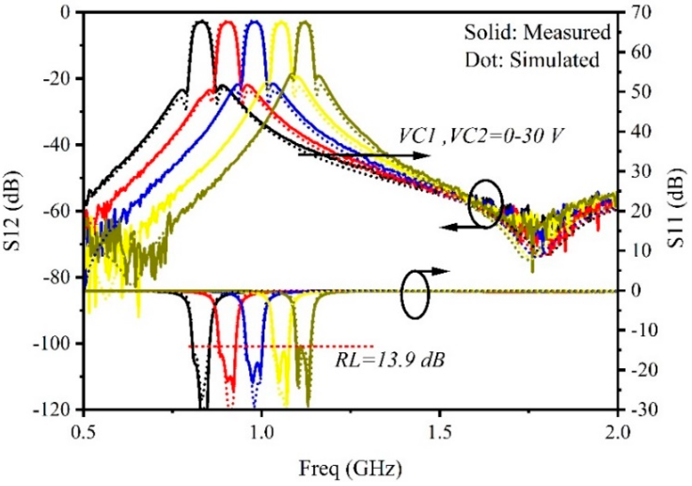
The measured frequency responses are obtained by using Keysight N5244A vector network analyzer. The measured and simulated frequency response is shown in Figure 16. The result shows that the center frequency of the proposed filter can be tuned from 0.8 to 1.14 GHz while varying the bias voltage VC1/VC2 from 0 to 30 V, the tuning range of the tunable BPF is about 35.1%. The return loss of the filter is better than 13.9 dB, and the insertion loss (IL) is 2.7–3.1 dB during the whole tuning range. The 3 dB ABW of the tunable filter is 47 ± 5 MHz; obviously, the constant ABW characteristic is realized. Two transmission zeros on both sides of the passband are generated, and the selectivity of the proposed filter is improved, and the rectangular coefficient (20 dB:3 dB) is 2.3–3.1. Another two transmission zeros located far from the passband are produced to improve the stopband performance. It can be seen that there are some deviations of S11 and S12 between the measured and simulated EM results. The deviation may be caused by mechanical tolerances and discontinuity of connectors. In addition, the series resistance of the varactor diode and mechanical tolerances make measured insertion losses higher than the simulated ones.
The performance comparison with some prior works is listed in Table 1. It can be seen that many fourth-order tunable filters achieve two or three TZs due to the cross-coupling structures between resonators; however, the tuning range (normalized by center frequency, %) of the filters are not good. The filter in [7] based on SIR realizes a 50% tuning range, but the selectivity of the filter is poor, and ABW of the filter can remain constant. The proposed tunable filter based on varactor-loaded SIR has a wide tuning range and small layout size compared with other high-order tunable filters. Moreover, four transmission zeros make the proposed tunable filter own high frequency selectivity and wide stopband performance. Additionally, the constant ABW characteristic is realized, and the characteristic is very useful in some practical applications.
Although the proposed tunable filter realizes good performance in terms of tuning range, number of TZs, selectivity, constant ABW and layout size, the insertion loss of the filter is about 3.1 dB, and it is still a little large, which may limit its applications in some practical scenarios. The large insertion loss is mainly caused by the equivalent resistance of the varactor diodes. Thus, how to reduce the insertion loss of fourth-order tunable filters may be an important work in the future. In addition, high-order filters are more likely to realize better frequency selectivity and wide stopbands, so it is also an interesting work to apply varactor-loaded SIRs to the design of sixth- or eight-order frequency tunable filters.
6. Conclusions
In this paper, a compact high-selectivity fourth-order tunable bandpass filter based on varactor-loaded step-impedance resonators with constant ABW is proposed. By establishing cross coupling between resonators, a pair of transmission zeros located close to the passband are generated, and the selectivity of the filter is enhanced significantly. Another pair of transmission zeros are produced to improve the out-of-band rejection by using source-load coupling. Meanwhile, by adopting a frequency-dependent coupling structure between resonators, the ABW of the proposed tunable filter remains constant during the whole tuning range. In addition, the proposed tunable filter has a wide tuning range and compact size due to the use of the varactor-loaded SIR. The good performance of the proposed tunable filter makes it attractive in modern wireless communication systems.
Author Contributions
The paper is completed by S.L. (Shuang Li), S.L. (Shengxian Li) and J.Y. Conceptualization, S.L. (Shuang Li) and S.L. (Shengxian Li); methodology, S.L. (Shuang Li); validation, S.L. (Shuang Li), S.L. (Shengxian Li) and J.Y.; formal analysis, S.L. (Shuang Li); investigation, S.L. (Shuang Li); writing—original draft preparation, S.L. (Shuang Li); writing—review and editing, S.L. (Shengxian Li) and J.Y.; project administration, S.L. (Shengxian Li). All authors have read and agreed to the published version of the manuscript.
Funding
The APC was funded by Xi’an Institute of Space Radio Technology.
Institutional Review Board Statement
Not applicable.
Informed Consent Statement
Not applicable.
Data Availability Statement
The data presented in this study are available on request from the corresponding author. The data are not publicly available due to privacy.
Conflicts of Interest
The authors declare no conflict of interest.
References
- Doumanis, E.; Goussetis, G.; Vuorio, J.; Hautio, K.; Amper, O.; Kuusmik, E.; Palonnen, J. Tunable Filters for Agile 5G New Radio Base Transceiver Stations. IEEE Microw. Mag. 2021, 22, 26–37. [Google Scholar] [CrossRef]
- Guyette, C. Intrinsically Switched Varactor-Tuned Filters and Filter Banks. IEEE Trans. Microw. Theory Tech. 2012, 60, 1044–1056. [Google Scholar] [CrossRef]
- Islam, H.; Das, S.; Bose, T.; Ali, T. Diode Based Reconfigurable Microwave Filters for Cognitive Radio Applications: A Review. IEEE Access 2020, 8, 185429–185444. [Google Scholar] [CrossRef]
- Kumar, N.; Narayana, S.; Singh, Y.K. Constant Absolute Bandwidth Tunable Symmetric and Asymmetric Bandpass Responses Based on Reconfigurable Transmission Zeros and Bandwidth. IEEE Trans. Circuits Syst. II Express Briefs 2021, 69, 1014–1018. [Google Scholar] [CrossRef]
- Zhang, Y.-J.; Cai, J.; Chen, J.-X. Design of Novel Reconfigurable Filter with Simultaneously Tunable and Switchable Passband. IEEE Access 2019, 7, 59708–59715. [Google Scholar] [CrossRef]
- Deng, H.-W.; Sun, L.; Liu, F.; Xue, Y.-F.; Xu, T. Compact Tunable Balanced Bandpass Filter with Constant Bandwidth Based on Magnetically Coupled Resonators. IEEE Microw. Wirel. Compon. Lett. 2019, 29, 264–266. [Google Scholar] [CrossRef]
- Qin, W.; Cai, J.; Li, Y.-L.; Chen, J.-X. Wideband Tunable Bandpass Filter Using Optimized Varactor-Loaded SIRs. IEEE Microw. Wirel. Compon. Lett. 2017, 27, 812–814. [Google Scholar] [CrossRef]
- Abdelfattah, M.; Zhang, R.; Peroulis, D. High-Selectivity Tunable Filters with Dual-Mode SIW Resonators in an L-Shaped Coupling Scheme. IEEE Trans. Microw. Theory Tech. 2019, 67, 5016–5028. [Google Scholar] [CrossRef]
- Lu, D.; Tang, X.; Barker, N.S.; Feng, Y. Single-Band and Switchable Dual-/Single-Band Tunable BPFs with Predefined Tuning Range, Bandwidth, and Selectivity. IEEE Trans. Microw. Theory Tech. 2018, 66, 1215–1227. [Google Scholar] [CrossRef]
- Chen, X.; Wu, Y.; Yang, Y.; Wang, W. Simple Coupled-Line Tunable Bandpass Filter with Wide Tuning Range. IEEE Access 2020, 8, 82286–82293. [Google Scholar] [CrossRef]
- Gao, L.; Rebeiz, G.M. A 0.97–1.53-GHz Tunable Four-Pole Bandpass Filter with Four Transmission Zeroes. IEEE Microw. Wirel. Components Lett. 2019, 29, 195–197. [Google Scholar] [CrossRef]
- Liu, Y.; Liu, L.; Liang, C.; Majid, I. Compact Planar Tunable Filter with Constant Absolute Bandwidth and Wide-Frequency Tuning Range Using DGS Coupling Structure. IEEE Access 2021, 9, 157259–157266. [Google Scholar] [CrossRef]
- Xiang, Q.; Sun, H.; Fu, M.; Jin, Q.; Feng, Q. A 5th-Order Constant Bandwidth Tunable Bandpass Filter with Two Cascaded Trisection Structures. IEEE Trans. Circuits Syst. II Express Briefs 2022, 70, 126–130. [Google Scholar] [CrossRef]
- Huang, X.; Feng, Q.; Zhu, L.; Xiang, Q.; Jia, D. Synthesis and design of tunable bandpass filters with constant absolute bandwidth using varactor-loaded microstrip resonator. Int. J. RF Microw. Comput.-Aided Eng. 2014, 24, 681–689. [Google Scholar] [CrossRef]
- Ohira, M.; Hashimoto, S.; Ma, Z.; Wang, X. Coupling-Matrix-Based Systematic Design of Single-DC-Bias-Controlled Microstrip Higher Order Tunable Bandpass Filters with Constant Absolute Bandwidth and Transmission Zeros. IEEE Trans. Microw. Theory Tech. 2018, 67, 118–128. [Google Scholar] [CrossRef]
- Tian, D.; Feng, Q.; Xiang, Q. Design of High Order Cross-Coupled Constant Absolute Bandwidth Frequency-Agile Bandpass Filters. Appl. Comput. Electromagn. Soc. J. 2019, 34, 1373–1378. [Google Scholar]
- Zhang, J.; You, C.J.; Jiao, Z.; Zhu, J.; Xiao, Q.; Cai, J. A tunable LTCC fourth-order bandpass filter with high selectivity for L-band satellite applications. Microw. Opt. Technol. Lett. 2021, 63, 1067–1072. [Google Scholar] [CrossRef]
- Wu, H.; You, B.; Gao, K.-K.; Li, X.-G. A 4th-Order LTCC Bandpass Filter with Both Tunable Center Frequency and Bandwidth. Electronics 2022, 11, 4119. [Google Scholar] [CrossRef]
- Li, X.; Zou, C.; Xiang, Q. Fourth-order Electrical Tunable Microstrip LC Cross-coupled Bandpass Filter. In Proceedings of the 2019 Photonics & Electromagnetics Research Symposium-Spring (PIERS-Spring), Rome, Italy, 17–20 June 2019; pp. 2076–2079. [Google Scholar]
- Wang, S.; Xiang, Q.; Feng, Q. A Fourth Order Constant Absolute Bandwidth Tunable Bandpass Filter with Cross-Coupling. In Proceedings of the 2019 IEEE MTT-S International Wireless Symposium (IWS), Guangzhou, China, 19–22 May 2019; pp. 1–3. [Google Scholar] [CrossRef]
- Cameron, R.J.; Kudsia, C.M.; Mansour, R.R. Microwave Filters for Communication Systems: Fundamentals, Design, and Applications; John Wiley & Sons: Hoboken, NJ, USA, 2018. [Google Scholar]
- Lu, D.; Yu, M.; Barker, N.S.; Li, Z.; Li, W.; Tang, X. Advanced Synthesis of Wide-Tuning-Range Frequency-Adaptive Bandpass Filter with Constant Absolute Bandwidth. IEEE Trans. Microw. Theory Tech. 2019, 67, 4362–4375. [Google Scholar] [CrossRef]
- Hong, J.-S.G.; Lancaster, M.J. Microstrip Filters for RF/Microwave Applications; John Wiley & Sons: Hoboken, NJ, USA, 2004; Volume 167. [Google Scholar]
- Anand, A.; Liu, X. Reconfigurable Planar Capacitive Coupling in Substrate-Integrated Coaxial-Cavity Filters. IEEE Trans. Microw. Theory Tech. 2016, 64, 2548–2560. [Google Scholar] [CrossRef] [Green Version]
Figure 1.
Coupling topology of the proposed filter.
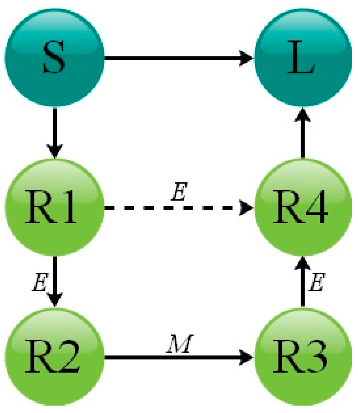
Figure 2.
Theoretical coupling coefficient and external quality for the predefined tunable filter based on the synthesis method introduced before.
Figure 2.
Theoretical coupling coefficient and external quality for the predefined tunable filter based on the synthesis method introduced before.
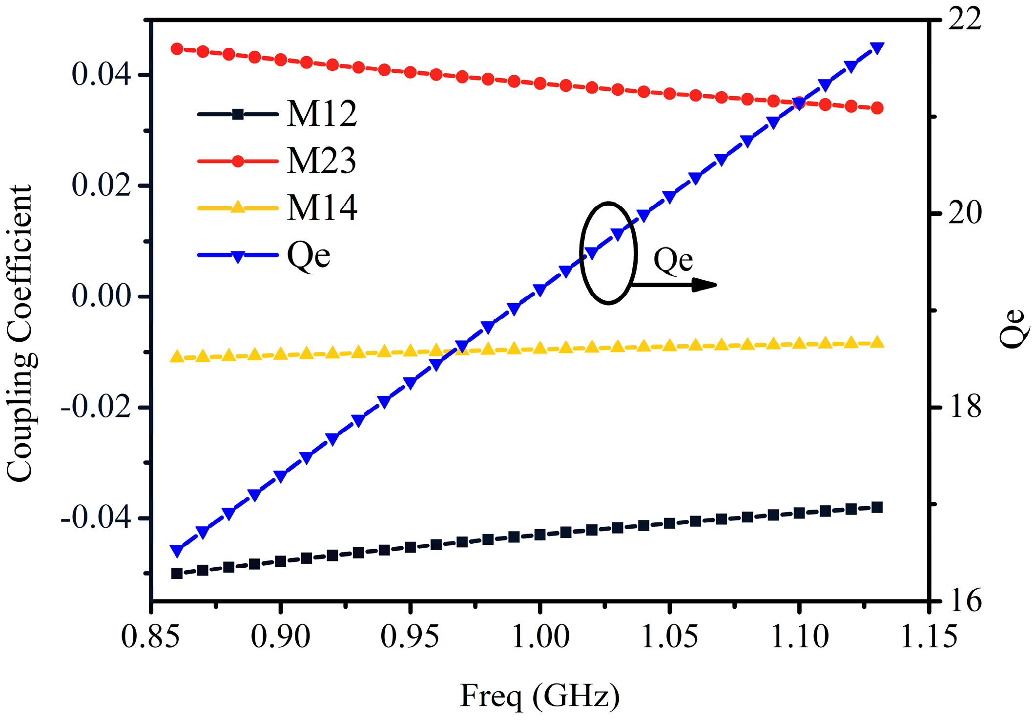
Figure 3.
Frequency response of the tunable filter during the whole tuning range.

Figure 4.
Layout of the proposed tunable SIR.

Figure 5.
Resonance frequency versus capacitance Cv with different values of θc, Y1 = 0.03 S, Y2 = 0.01 S, θ1 = θ2 = 90°, where the reference frequency is 1GHz.
Figure 5.
Resonance frequency versus capacitance Cv with different values of θc, Y1 = 0.03 S, Y2 = 0.01 S, θ1 = θ2 = 90°, where the reference frequency is 1GHz.

Figure 6.
Tuning range of the tunable SIR versus electronic length ratio α with different values of characteristic impedance β, Y1 = 0.03 S, θc = 20°, θ1 + θ2 = 180°, where the reference frequency is 1 GHz.
Figure 6.
Tuning range of the tunable SIR versus electronic length ratio α with different values of characteristic impedance β, Y1 = 0.03 S, θc = 20°, θ1 + θ2 = 180°, where the reference frequency is 1 GHz.
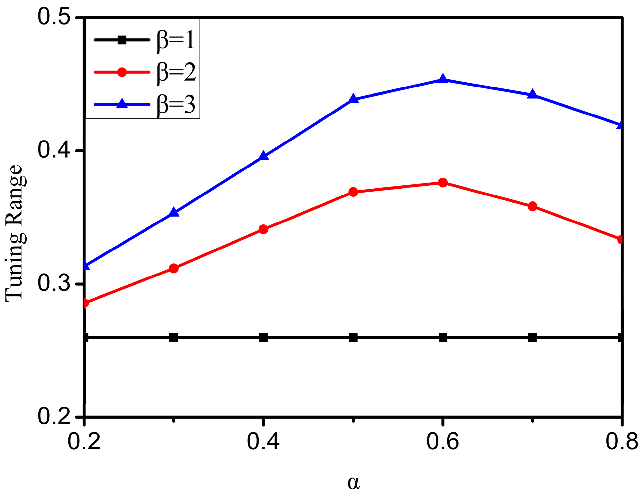
Figure 7.
The proposed frequency-dependent electric coupling structure.
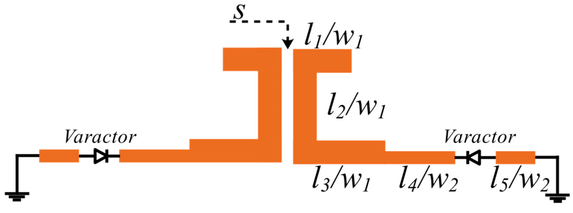
Figure 8.
Electric coupling coefficient versus efficient capacitance Cv with different values of coupling slot s and locating position l5, w1 = 2 mm, w2 = 1 mm, l1 = 5 mm, l2 = 25 mm, l3 = 20.5 mm, l4 + l5 = 37.5 mm.
Figure 8.
Electric coupling coefficient versus efficient capacitance Cv with different values of coupling slot s and locating position l5, w1 = 2 mm, w2 = 1 mm, l1 = 5 mm, l2 = 25 mm, l3 = 20.5 mm, l4 + l5 = 37.5 mm.

Figure 9.
The proposed frequency-dependent magnetic coupling structure.
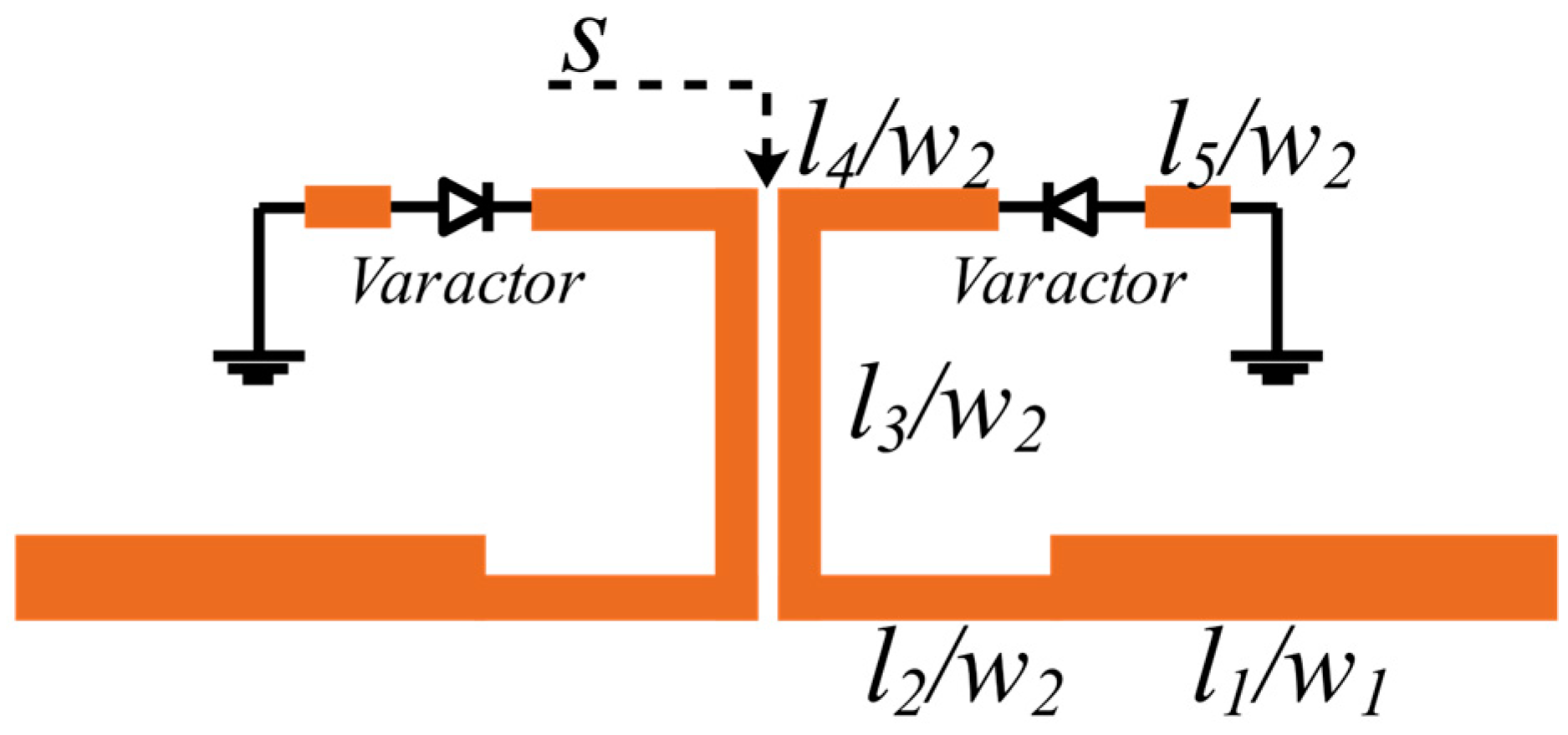
Figure 10.
Magnetic coupling coefficient versus efficient capacitance Cv with different values of coupling slot s and l4, w1 = 2 mm, w2 = 1 mm, l1 = 5 mm, l2 = 25 mm, l3 = 20.5 mm, l4 + l5 = 37.5 mm.
Figure 10.
Magnetic coupling coefficient versus efficient capacitance Cv with different values of coupling slot s and l4, w1 = 2 mm, w2 = 1 mm, l1 = 5 mm, l2 = 25 mm, l3 = 20.5 mm, l4 + l5 = 37.5 mm.
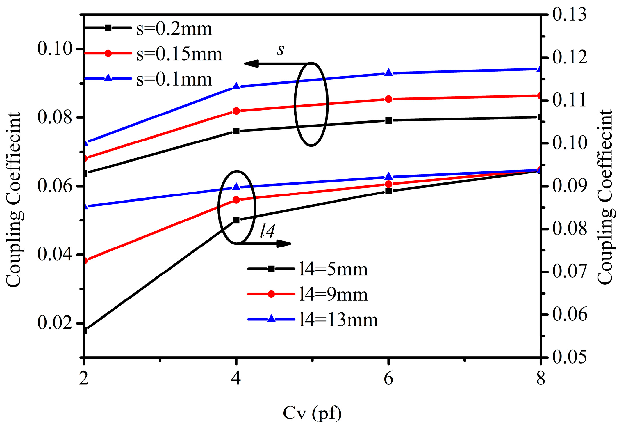
Figure 11.
The feeding structure of the varactor-loaded SIR.

Figure 12.
The external quality Qe versus efficient capacitance cv with different values of coupling slot s and locating position l1. w1 = 1 mm, w2 = 2 mm, w3 = 1.2 mm, l1 + l2 = 37.5 mm, l3 = 37.5 mm, l4 = 53 mm.
Figure 12.
The external quality Qe versus efficient capacitance cv with different values of coupling slot s and locating position l1. w1 = 1 mm, w2 = 2 mm, w3 = 1.2 mm, l1 + l2 = 37.5 mm, l3 = 37.5 mm, l4 = 53 mm.

Figure 13.
Layout of the proposed tunable filter with CABW.
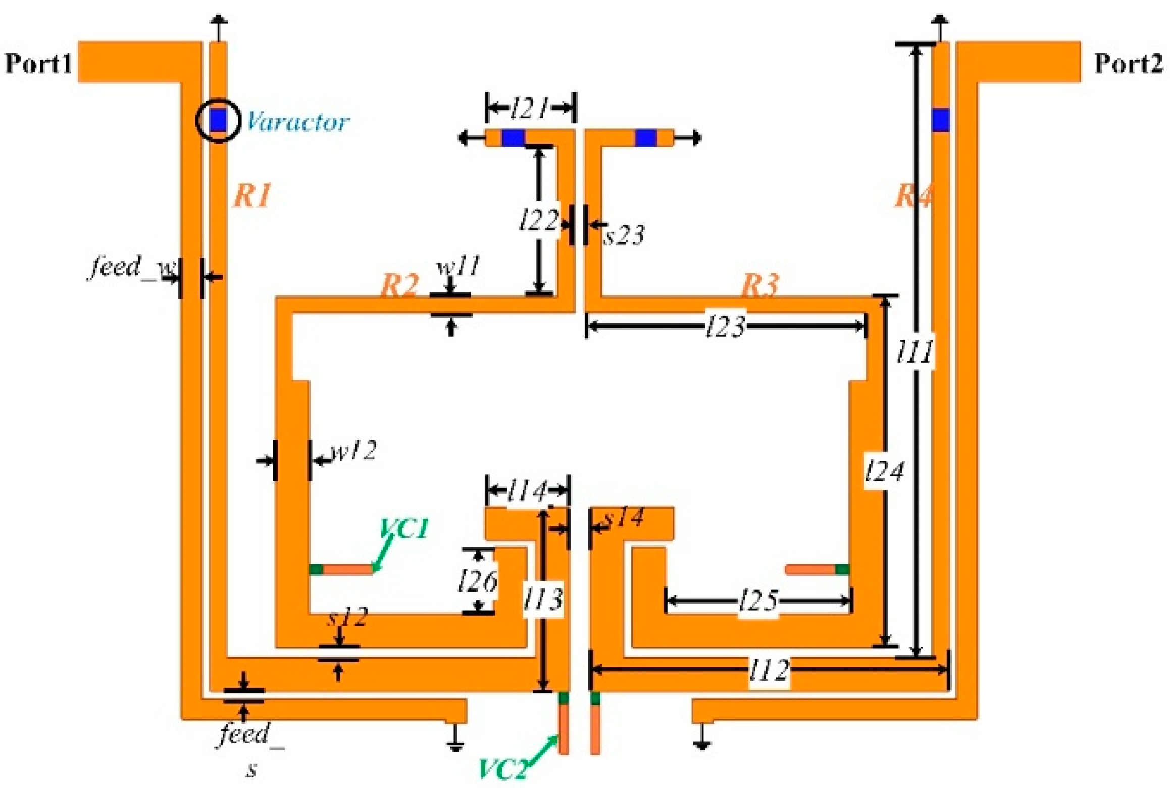
Figure 14.
The ideal and simulated coupling coefficient and external quality Qe for the predefined design goal.
Figure 14.
The ideal and simulated coupling coefficient and external quality Qe for the predefined design goal.
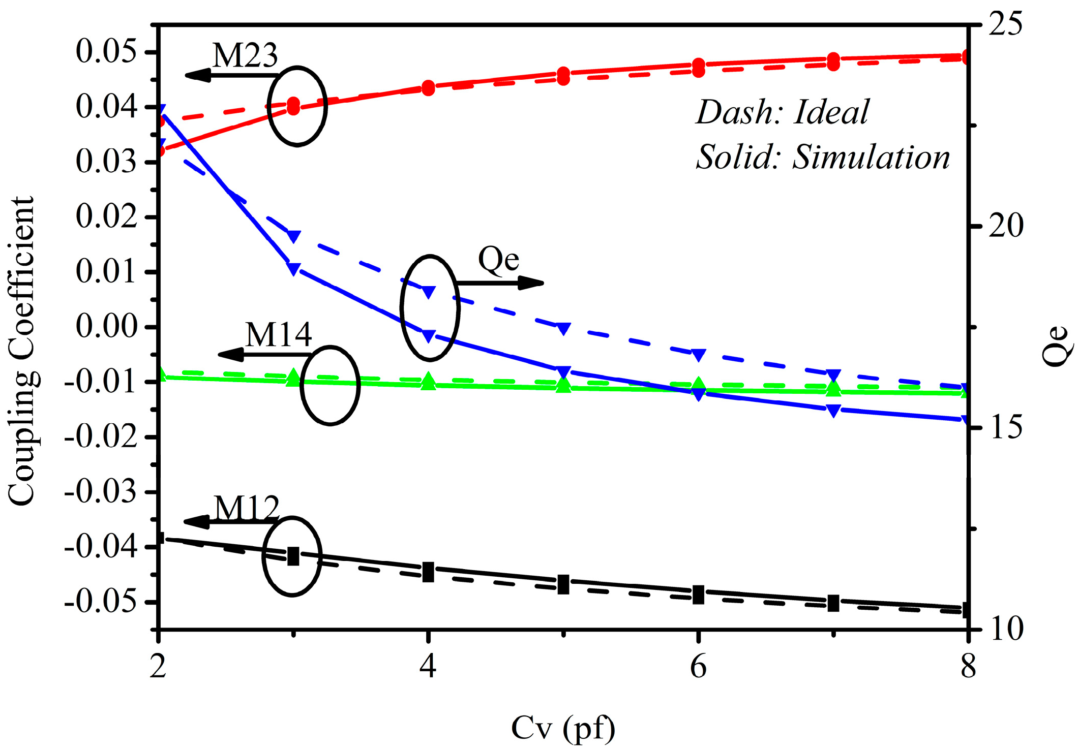
Figure 15.
The photograph of the fabricated filter.
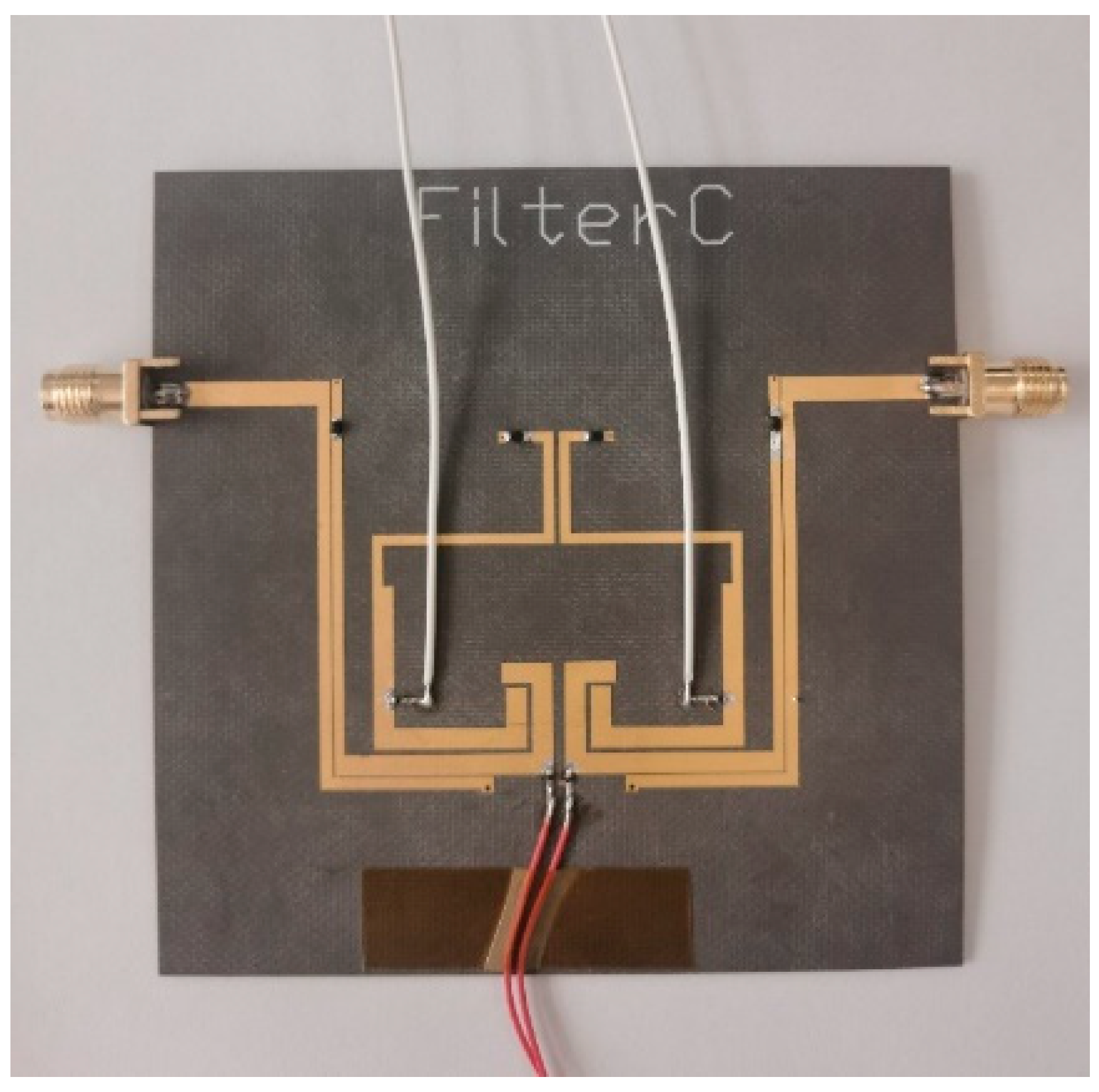
Figure 16.
Simulated and measured frequency response of the proposed tunable BPF.

Table 1.
Typical performance comparison with prior works.
| REF. | Freq (GHz) | TR (%) | BW (MHz) | IL (dB) | Order | NTZ 3 | Resonator | CABW 2 | Size (λg × λg) |
|---|---|---|---|---|---|---|---|---|---|
| [4] | 1.5–1.8 | 18.1 | 119 | 2.5 | 2 | 0 | UIR | YES | 0.18 × 0.13 |
| [7] | 0.6–1 | 50 | 93–155 | 2.8 | 2 | 0 | SIR | NO | 0.19 × 0.19 |
| [13] | 1.48–1.88 | 23 | 92 | 5.6 | 5 | 2 | UIR | YES | NG |
| [15] | 0.89–1.13 | 23.8 | 46.8 | 4.3 | 4 | 2 | UIR | YES | 0.23 × 0.19 |
| [17] | 1.26–1.61 | 24.4 | 176–225 | 2.3 | 4 | 2 | UIR | NO | 0.09 × 0.08 |
| [18] | 2.86–3.2 | 13 | 170–320 | 6.85 | 4 | 3 | NG1 | NO | 0.3 × 0.17 |
| [19] | 2–2.45 | 20.2 | 104–135 | 6.85 | 4 | 2 | LC | NO | NG 1 |
| [20] | 1.36–1.78 | 26.6 | 93 | 5 | 4 | 2 | UIR | YES | NG 1 |
| [22] | 1.21–1.58 | 26.8 | 133 | 3 | 4 | 4 | UIR | YES | 0.73 × 0.11 |
| [24] | 2.24–2.64 | 16.3 | 240 | 3.9 | 4 | 1 | SIW 4 | YES | NG 1 |
| Proposed | 0.8–1.14 | 35.1 | 47 | 3.1 | 4 | 4 | SIR | YES | 0.14 × 0.17 |
1 Not Given; 2 constant ABW; 3 numbers of TZ; 4 substrate-integrated waveguide.
Disclaimer/Publisher’s Note: The statements, opinions and data contained in all publications are solely those of the individual author(s) and contributor(s) and not of MDPI and/or the editor(s). MDPI and/or the editor(s) disclaim responsibility for any injury to people or property resulting from any ideas, methods, instructions or products referred to in the content. |
© 2023 by the authors. Licensee MDPI, Basel, Switzerland. This article is an open access article distributed under the terms and conditions of the Creative Commons Attribution (CC BY) license (https://creativecommons.org/licenses/by/4.0/).
Share and Cite
MDPI and ACS Style
Li, S.; Li, S.; Yuan, J. A Compact Fourth-Order Tunable Bandpass Filter Based on Varactor-Loaded Step-Impedance Resonators. Electronics 2023, 12, 2539. https://doi.org/10.3390/electronics12112539
AMA Style
Li S, Li S, Yuan J. A Compact Fourth-Order Tunable Bandpass Filter Based on Varactor-Loaded Step-Impedance Resonators. Electronics. 2023; 12(11):2539. https://doi.org/10.3390/electronics12112539
Chicago/Turabian StyleLi, Shuang, Shengxian Li, and Jianrong Yuan. 2023. "A Compact Fourth-Order Tunable Bandpass Filter Based on Varactor-Loaded Step-Impedance Resonators" Electronics 12, no. 11: 2539. https://doi.org/10.3390/electronics12112539
Note that from the first issue of 2016, this journal uses article numbers instead of page numbers. See further details here.