

Bionic Design of a Novel Portable Hand-Elbow Coordinate Exoskeleton for Activities of Daily Living
by
 ,
,
Qingyun Meng
1,2,3,
Guanxin Liu
1,2,
Qiaoling Meng
2,
Xin Xu
2,3,
Liang Qin
1,3 and
Hongliu Yu
2,* 1
College of Medical Instruments, Shanghai University of Medicine and Health Sciences, Shanghai 201318, China
2
Institute of Rehabilitation Engineering and Technology, University of Shanghai for Science and Technology, Shanghai 200093, China
3
Shanghai Engineering Research Center of Wearable Medical Technology and Devices, Shanghai 201318, China
*
Author to whom correspondence should be addressed.
Electronics 2023, 12(15), 3326; https://doi.org/10.3390/electronics12153326
Submission received: 5 April 2023
/
Revised: 2 August 2023
/
Accepted: 2 August 2023
/
Published: 3 August 2023
(This article belongs to the Special Issue Advanced Wearable/Flexible Devices and Systems in Bioelectronics)
Abstract
:This paper presents the mechanical design and test of a portable hand-elbow combination linkage upper limb rehabilitation robot, which can realize the joint movement of the hand joint and elbow joint and reproduce the complete grasping action. The joints that need bionic support are determined according to the characteristics of human upper limbs and hands, and the overall bionic mechanism is designed. The Motion module in SolidWorks is used to simulate and analyze the rehabilitation robot. The measurement experiment and grasping experiment of joint mobility are carried out on the experimental prototype. As a result, the angular displacement and linear displacement curves obtained via the simulation results are smooth. The measurement experiment of the joint range of motion confirms that the joint range of motion is also within the range of the normal joint angle of the human body, and the grasping experiment shows that the exoskeleton can grasp and lift a 1.801-kg cylindrical object and other daily necessities of different shapes. This result shows that the design of the portable hand-elbow combination linkage upper limb rehabilitation robot is reasonable, can satisfy the rehabilitation training requirements of the hand and upper limb, and has some ability to assist users in daily life.
1. Introduction
Stroke, which is a disease characterized by cerebral ischemia and hemorrhagic injury, is known for its high incidence rate, high mortality, high disability rate, high recurrence rate, and numerous complications [1,2]. According to the Global Burden of Disease Report published by the World Health Organization, the year 2019 saw 12.2 million new cases of stroke diagnosed, 101 million existing cases of stroke exist, 143 million disability-adjusted life years (DALYs) attributed to stroke, and 6.55 million deaths caused by stroke [3]. Globally, stroke remained the second most prevalent cause of death, accounting for 11.6% of total deaths, and the third most prevalent cause of death and disability combined, accounting for 5.7% of total DALYs, in 2019.
After the onset of stroke, it is often accompanied by a variety of functional injuries, such as language function, upper limb motor function, lower limb motor function, etc. Among these functional injuries, upper limb motor function injury accounts for a high proportion, and about 65% of stroke patients still have upper limb motor dysfunction within 3–6 months of the operation [4]. Existing experimental studies have confirmed that continuous passive enhanced periodic training of patients’ upper limbs can effectively prevent muscle disuse atrophy and contribute to the recovery of a patient’s upper limb motor function [5,6].
The traditional rehabilitation treatment method is to carry out one-to-one or one-to-many special rehabilitation training for patients through physiotherapy, and most recently, upper limb rehabilitation training [7] has become a research hotspot in society. Upper limb exoskeletons are wearable exoskeleton devices specifically designed for the human upper limbs, aiming to enhance upper limb function and mobility. They can support and assist movements of the arms, shoulders, and hands, helping individuals with daily activities and specific tasks. Upper limb exoskeletons are widely used in fields such as medical rehabilitation, industrial workforce augmentation, and assistive functional activities. Upper limb exoskeletons are considered to be a viable form of treatment for many conditions, such as post-stroke rehabilitation, traumatic brain injury (TBI), spinal cord injury (SCI), and neurodegenerative diseases [8]. Cappello et al. [9] described the design of a soft exoskeleton with a single actuator for the elbow joint that can control flexion and extension simultaneously, aiming to enhance the strength of human users. The design approach of the CLEVER arm [10] allows the use of carbon fiber-reinforced 3D-printed links and the design and control of the shoulder joint, reducing the weight of the exoskeleton while maintaining high rigidity and torque. With the continuous development of exoskeleton-related technologies, the increasing assistive capabilities provided by exoskeletons are expected to address the issue of prolonged static posture [11]. However, the development of such devices still faces the following challenges: (1). Power and energy management: upper limb exoskeletons require efficient power systems to provide sufficient force and prolonged battery life. The weight and size of the batteries need to be considered to ensure the device is lightweight and portable. (2). Human–machine interaction and control: Designing user-friendly and controllable interfaces is crucial for upper limb exoskeletons. Users should be able to control the device easily and receive accurate feedback and sensations to help them achieve natural and intuitive movements. (3). Degrees of freedom and adaptability: upper limb exoskeletons need to have multi-joint degrees of freedom and flexible designs that accommodate different arm morphologies and movements, ensuring the practicality of the device.
At present, many types of upper limb rehabilitation training systems [12,13,14,15] have been introduced into hospitals as intelligent equipment, but they have not been widely popularized because of their non-portability, large volume, and high cost. And most of the existing upper limb rehabilitation training devices can only recover the shoulder, elbow, and wrist of the upper limb, which cannot effectively combine hand rehabilitation with upper limb rehabilitation. The hand is an indispensable body part that people use in activities of daily living. Indeed, 60% of the activities in life need to be realized using the upper limb, and the function of the hand accounts for 90% of the function of the upper limb [15,16]. It can be seen that hand rehabilitation is important to patients’ upper limb rehabilitation.
As is well known, the human upper limbs and hands have a total of 18 joints and 27 degrees of freedom. The coordinated functioning of these joints allows the human hand to grasp objects in space in various postures. However, stroke patients experience issues, such as muscle weakness or excessive muscle tone, related to the driving muscle groups of these joints due to damage to the central nervous system, resulting in a reduction in the range of motion of the joints. For example, after the onset of the disease, the shoulder muscles may experience muscle relaxation, leading to shoulder weakness. The elbow muscles may exhibit excessive tension in the biceps brachii and inadequate strength in the triceps brachii, making elbow flexion and extension difficult. The hand muscles may suffer from spasms after the disease, preventing independent extension of the hand joints.
According to the above characteristics analysis, it is necessary to design a bionic mechanism to replace the human shoulder joint, elbow joint, and hand joint muscle groups to realize joint drive. The driving torques that correspond to the three degrees of freedom of the shoulder joint (pronation/extra rotation, flexion/extension, and adduction/abduction) are 6.5 N·m, 11 N·m, and 5.5 N·m, respectively; The corresponding driving torque of elbow flexion and extension is 4 N·m, and the driving torque that corresponds to the movement of one finger of the hand is 1 N·m [17]. Due to the characteristics of many degrees of freedom and the large driving torques, the total weight of the shoulder joint driving system can generally reach more than 2.2 kg [18], which is much heavier than that of the elbow and hand joint driving system. Considering that the weight and volume of the rehabilitation trainer are too large, the rehabilitation robots are not portable, which greatly affects their popularization and application in families or communities, and the final rehabilitation trainer discards the bionic shoulder joint and chooses to replace the elbow joint and hand joint with the bionic mechanism. Moreover, in the design of the hand bionic mechanism, considering that the position and function of the thumb are different from those of the four fingers, the thumb mechanism should be separately designed. At the same time, the distal interphalangeal joint of the four fingers has a certain work relationship with the proximal interphalangeal joint [15,16,17,18,19], that is, the movement of the proximal interphalangeal joint will drive the movement of the distal interphalangeal joint. Therefore, in the design of the hand joint mechanism of the elbow joint rehabilitation trainer, the bionics of the proximal interphalangeal joint and metacarpophalangeal joint can realize the complete flexion and extension of fingers.
Based on the above issues, this study designs a new type of portable elbow joint rehabilitation trainer that is lightweight, portable, safe, and effective, primarily targeting patients with upper limb hemiplegia. By wearing the portable elbow joint rehabilitation trainer, patients can perform coordinated rehabilitation training for their hands and elbow joints at any location, without the need to visit a designated rehabilitation center, thereby saving rehabilitation time. After a stroke, patients with stiff finger joints initiate their hand movements from a bent position. Achieving sufficient hand opening is crucial for performing activities of daily living (ADL) [20]. When designing the exoskeleton joint range, we primarily consider the following three aspects: (1). Feix et al. [21] found that a grip size of 7 cm or smaller is sufficient to encompass 90% of objects in the grip dataset for healthy individuals. In 83% of cases, the required grip size is less than 5 cm. Therefore, to accommodate a wide range of objects for gripping, the device should be capable of achieving at least a 5-cm grip size, and preferably a 7-cm grip size. To achieve an opening greater than 5 cm with the average finger size, a bending angle of approximately 10° (MCP joint) and 20° (PIP joint) in the index finger is necessary [20]. (2). Based on past research into relevant hand exoskeletons, it has been proven that as long as the MCP and PIP joints of the finger components each provide approximately 65° of range of motion (ROM), the exoskeleton can perform various rehabilitation exercises [22]. (3). As the device is intended for a population that includes patients with limited joint mobility in the early stages of rehabilitation, early- and moderate-intensity activities can significantly reduce a range of complications caused by prolonged bed rest [23]. To ensure patient safety and avoid re-injury, an exoskeleton is chosen that has moderate angles and meets the requirements stated in (1) and (2). The exoskeleton mechanism is designed to support daily activities and assist in gripping everyday objects, ensuring that the joint range of motion of the exoskeleton falls within the normal range of motion of a healthy human joint [24], as shown in Table 1, which includes the specific mechanical parameters of the exoskeleton. Based on the characteristics of the human upper limb and hand, this study determines the need for bionic joints. Subsequently, a bionic mechanism is designed to replace the impaired muscle groups responsible for the patient’s movement dysfunction, and motion simulation analysis and force analysis of each joint of the elbow joint rehabilitation trainer are performed to demonstrate the correctness of the structural design. Finally, measurement experiments of joint range of motion and gripping capabilities are conducted on the prototype to examine whether the exoskeleton’s range of motion falls within the normal range of motion of a healthy human joint and whether it satisfies the function of assisting in gripping, thus verifying the feasibility of the exoskeleton.
2. Overall Mechanical Structure Design
The portable hand-elbow combination linkage upper limb rehabilitation robot (Figure 1) is mainly divided into an elbow function module and a hand function module. Each functional module is driven by speed reduction motors of different specifications, and the action of the thumb in the hand functional module is driven by a micro-speed reduction motor alone. The elbow function module and the hand function module are connected by a slider–crank mechanism that lacks a power source, which can adapt to the patient’s wrist flexion and extension. In addition, to ensure the comfort of the elbow joint rehabilitation trainer, breathable cushioning materials are placed at the contact part between the trainer and the human body, and elastic bandages are used to fix the upper limbs of patients with the re-habilitation trainer. To ensure the safety of patients and prevent secondary injury, mechanical limits are set at each joint of the elbow joint rehabilitation trainer, and limit switches are set at the output end of the reduction motor.
Figure 1 depicts the three-dimensional representation of the entire mechanical structure.
2.1. Elbow Function Module
The elbow function module (Figure 2) is composed of an upper arm bracket, elbow speed reduction motor, secondary deceleration synchronous belt, and pre-loaded spring. The upper arm bracket is made of memory alloy material, which can adapt to upper arms of different sizes. The position of the upper arm bracket can also be adjusted by pressing the spring pin on the arm bracket. The secondary deceleration synchronous belt is used to move the elbow speed reduction motor up to the lower part of the triceps brachii, which can reduce the load torque of the body weight on the shoulder joint and prevent the locked rotation of the elbow speed reduction motor. The pre-loading of the built-in coil spring at the elbow joint of the rehabilitation trainer can realize the gravity balance of the forearm mechanism and the hand mechanism, reduce the energy loss of the motor, and increase the flexibility of the mechanism (see Appendix A for the parameters of the exoskeleton).
In addition, the upper arm bracket adopts the underactuated slider mechanism. As shown in Figure 3, s represents the distance between the two underactuated sliders, M represents the driving torque that the elbow drive module can provide, and δ represents the distance between the center of the pre-loaded spring and the elbow rotation center. With the movement of the whole elbow function module, the value of δ can be reduced to zero to achieve the coincidence of the two centers of rotation.
At the same time, the forearm bracket can adaptively slide on the upper arm bracket in the process of elbow flexion and extension movement. Thus, the motion impact caused by the misalignment of the rotation centers of human–machine joints can be eliminated.
2.2. Hand Function Module
The hand function module is composed of a hand support plate, a four-finger training module, and a thumb training module. The four-finger training module (Figure 4a) includes a reduction motor, a reduction gearbox, and a four-finger actuator. The reduction motor and reduction gearbox are installed and fixed on the hand support plate, and the reduction motor transmits the power to the four-finger actuator through the reduction gearbox. The four-finger actuator is composed of a spatial four-bar mechanism and slider–crank mechanism (Figure 4b), which can synchronously drive the metacarpophalangeal and proximal interphalangeal joints of the four fingers. The geometric dimensions of the slider–crank mechanism are determined based on the dimensions of the proximal and middle phalanxes of the human hand. The rotational centers of the mechanism can adaptively match the metacarpophalangeal joints and proximal interphalangeal joints of the hand, ensuring the effectiveness and safety of the hand function module during the operation and training processes.
The thumb training module (Figure 5) includes a three-degree freedom damping link, a micro reduction motor, an incomplete gear set, and a thumb actuator. By manually adjusting the angle of the three degrees of freedom damping connecting rod, the position of the thumb actuator can be changed to cooperate with the four fingers to realize the multi-posture grasping action. When the micro-reduction motor moves, the output end of the motor passes through the external incomplete gear set and transmits the power to the thumb actuator to drive the thumb flexion and extension movement. The thumb actuator is a slider–crank mechanism.
3. Kinematic Simulation Analysis
The correct grasping motion of the human hand toward objects in space is achieved by first approaching the object through movements of the shoulder and elbow joints, before adjusting the grasping posture through the wrist joint and, finally, achieving precise gripping through movements of the hand joints. Therefore, when simulating the motion of the elbow joint rehabilitation training device, it is necessary to sequentially simulate the movements of the elbow and hand joints to verify the correctness of the structural design of the elbow joint rehabilitation training device.
3.1. Motion Simulation of the Elbow Function Module
The hand-elbow combination linkage upper limb rehabilitation robot adopts the motion simulation analysis carried out via the motion simulation module using SolidWorks software [25]. The rated speed of the elbow reduction motor is set at 40 r/min, and the rated torque is set at 1.8 N·m. After passing through the secondary deceleration synchronous belt with a reduction ratio of 4:1, the final output speed of the elbow is 10 r/min. At the same time, in order to prevent stroke patients from experiencing secondary injury caused by excessive stretching of the limbs under the condition of excessive elbow muscle tension, the maximum joint range of motion of the elbow of the rehabilitation trainer is set at 120° [26]. Therefore, the calculation of simulation period is shown in the following formula:
where θ (°) is the motion angle of the driving output rod, and n (r/min) is the final output speed of the joint. We apply the elbow data to Equation (1) to obtain a simulation cycle of T = 4 s.
The angular displacement curve of the elbow joint and the linear displacement curve of the metacarpophalangeal joint (the reference point is the metacarpophalangeal joint of the index finger when the angular displacement of the elbow joint is 0°, and the vertical direction is the positive direction) can be obtained by extracting and analyzing the data after motion simulation. The simulation results are shown in Figure 6 and Figure 7.
It can be seen in the simulation curve that the angular displacement curve of the elbow joint and the linear displacement curve of the metacarpophalangeal joint gently change in the process of one-time flexion and extension simulation of the elbow function module. This outcome shows that the starting and ending movements of the rehabilitation trainer mechanism are slow, and the movement process is stable, which is consistent with the movement of the human elbow joint.
3.2. Motion Simulation of the Hand Function Module
Since the four fingers have the same physiological characteristics and bionic mechanism, in this study, the forefinger is taken as the simulation object of the four fingers. To ensure the safety of patients using the hand-elbow combination linkage upper limb rehabilitation robot, the set values of the range of motion of each joint of the hand are within the range of motion of healthy people [27]. The rated speed of the reduction motor of the four-finger training module is 1100 r/min, and the rated torque is 0.062 N·m. After using a reduction gearbox with a reduction ratio of 100:1, the final output speed is 11 r/min, the output torque is 6.2 N·m, and the movement angle of the four-finger push rod connected to the output shaft of the reduction gearbox is 130°.
When the data of the four-finger training module are applied to Equation (1), it can be concluded that the simulation cycle of four-finger training is 3.94 s. The rated speed of the micro reduction motor of the thumb training mechanism is 60 r/min, and the rated torque is 0.055 N·m. After passing through the incomplete gear set with an external reduction ratio of 10:1, the final output speed is 6 r/min, and the output torque is 0.55 N·m. The motion angle of the thumb push rod connected to the output shaft of the incomplete gear set is 71.5°. By applying the data of the thumb training module to Equation (1), a thumb training simulation cycle of 3.97 s can be obtained. After a complete hand grasping simulation, the angular displacement curves of the metacarpophalangeal joint of the index finger, the proximal interphalangeal joint of the index finger, and the interphalangeal joint of the thumb can be obtained. The simulation curve is shown in Figure 8.
In Figure 8, the angular displacement curves of each joint of the hand gently change, and the ranges of motion of the metacarpophalangeal joint, proximal interphalangeal joint, and thumb interphalangeal joint are 0~84°, 0~73°, and 0~49°, respectively. The angular displacement curve of the proximal interphalangeal joint stays at the maximum angle for about 0.3 s, as there is no relative displacement between the slider and chute of the proximal interphalangeal joint in the four-finger actuator during this time period.
3.3. Workspace Analysis
The workspace of an exoskeleton is an important indicator used to evaluate its feasibility. It represents the motion performance of the robot and directly influences its practical application value. In the elbow joint rehabilitation trainer, we take the palm position point P of the trainer as the endpoint (Figure 9a). By imposing angle constraints on the wrist and elbow joints and using the Monte Carlo random sampling method, we generate a large number of endpoint positions to visualize the robot’s workspace (Figure 9b).
As shown in the figure, the simulated workspace results align with the human workspace and conform to the physiological parameters of the human body. This result proves that the robot is capable of meeting the requirements of rehabilitation training.
4. Prototype Experiment
After completing the motion simulation of the mechanism, a prototype of a portable elbow-linked upper limb rehabilitation robot was produced, and the prototype had adjustable settings to accommodate different users. Non-load-bearing components of the experimental prototype were fabricated using 3D printing technology, resulting in it having a total weight of approximately 1.5 kg. To verify the operational performance of the upper limb rehabilitation robot, this study recruited six healthy adults to participate in joint range of motion measurement and grip experiments while wearing the experimental prototype. The information of the participants is shown in Table 2, and all participants had no neurological impairments or diseases.
4.1. Joint Range of Motion Measurement Experiment
The joint range of motion measurement experiment was primarily conducted to obtain the range of motion of the elbow joint, finger joints (proximal interphalangeal joint and thumb interphalangeal joint), and wrist joint when patients wore the exoskeleton for rehabilitation training. Under the passive control mode, Participant 1 and Participant 2 wore the exoskeleton while in a standing position and performed five cycles of flexion and extension movements. The extreme positions of each flexion/extension motion were captured using a camera, and the joint range of motion was measured based on the marked points on the participants’ joints. In this context, the symbol α represents the elbow joint range of motion, the symbol β represents the range of motion of the index and middle finger joints, the symbol γ represents the range of motion of the proximal interphalangeal joint, and the symbol θ represents the range of motion of the thumb interphalangeal joint. The angles of each joint were determined for each motion cycle and averaged, as shown in Table 3 and Table 4. Throughout the entire experimental process, the movements were smooth and stable and lacked any interference, confirming the rationality of the design structure.
By comparing the actual maximum joint activity of each joint with the maximum joint activity of the simulation analysis, we found that the actual measured value was less than 5–10° of the simulation result in Figure 8. This outcome occurred because the human body is not a pure rigid body. While wearing the hand-elbow joint rehabilitation trainer, there is still relative motion between the experimenter’s muscles and bones, which would result in the range of motion of the human skeleton being slightly smaller than that of the hand-elbow joint rehabilitation trainer. The testing process is shown in Figure 10 and Figure 11.
4.2. Grasping Experiment
To verify the bionics of the portable hand-elbow joint rehabilitation exoskeleton robot, a grasp strength test platform [28] (Figure 12) was built to test the hand grasp strength of the hand-elbow combination linkage of the upper limb rehabilitation robot. The experimenter was not permitted to use his strength during the grasp test, and the elbow joint had to be kept in a horizontal position. By grasping two kinds of cylinders (φ43 mm and φ65 mm, respectively) that were similar to the diameter of the water cup used in daily life and slowly pulling them vertically and horizontally until relative sliding started to occur, the value of the tension meter was read. After five tensile tests were performed on the cylinders that were φ43 mm and φ65 mm in diameter, respectively, and taking the average value, it was concluded that the average grasp force of the φ43-millimeter cylinder was 11.34 N, the average grasp force of the φ65-millimeter cylinder was 17.65 N, and the grasp force was equal to the weight of the cylinder grasped by the hand-elbow combined rehabilitation trainer.
Additionally, multiple everyday items with significant geometric variances were used in the grasp test, and Participant 1 conducted the physical grasp test while wearing the upper limb rehabilitation robot. Seven commonly used items were selected: a pen (a cylindrical object measuring 150 mm in length and 10 mm in diameter), card (a rectangular object measuring 88 mm in length, 63 mm in width, and 1 mm in height), book (a rectangular object measuring 230 mm in length, 170 mm in width, and 10 mm in height), water cup (a cylindrical object measuring 160 mm in height and with a maximum diameter of 70 mm), apple (a spherical object with a diameter of 80 mm), towel (a rectangular object measuring 70 mm in length, 50 mm in width, and 33 mm in height), and water bottle (a bottle measuring 220 mm in height, 64 mm in bottle body diameter, 30 mm in bottle mouth diameter, and 52 mm in bottle bottom diameter). All items were tested once, and the grasping experiments were all successful. As shown in Figure 13, the exoskeleton was capable of grasping items of various sizes, which shows that the portable hand-elbow combination linkage upper limb rehabilitation robot can provide some daily life assistance to people with upper limb motor dysfunction. In the next phase of our work, we will focus on increasing the sample size and testing the accuracy of the exoskeleton.
Furthermore, to verify the universality of the designed exoskeleton, Participant 3 used the exoskeleton hand to perform a physical grasping experiment. During the experiment, Participant 3 was able to complete the task of picking up and drinking from a cup with the assistance of the exoskeleton device without applying any active force, as shown in Figure 14. The experimental object used was a porcelain cup with a volume of 300 mL (which was filled with water during the experiment), and no significant shaking or abnormalities occurred during the experiment. The experiment demonstrated that the exoskeleton was able to successfully perform the pre-determined action of retrieving water, thus exhibiting good auxiliary gripping capability.
Further, grasp tests using the hand exoskeleton were conducted by participants 4, 5, and 6. During the experiment, each participant performed grasping tasks with the assistance of the hand exoskeleton and using different objects. Participant 1 grasped a pen (a cylindrical object measuring 150 mm in length and 10 mm in diameter), Participant 2 grasped a tissue box (measuring 195 mm in length, 120 mm in width, and 50 mm in height), and Participant 3 grasped a water cup (with a maximum diameter of 88 mm and a minimum diameter of 60 mm), as shown in Figure 15. Throughout the experiment, there were no noticeable tremors or anomalies. The experiment demonstrated that the hand exoskeleton performed well in executing the intended grasping actions, exhibiting excellent auxiliary grip capabilities. The device can effectively achieve the designed goal of assisting users with daily living activities.
5. Conclusions
This paper presents a portable hand-elbow combination linkage upper limb rehabilitation robot, which can carry out rehabilitation training of hand and elbow joints, as well as reproduce the complete grasping action of the upper limb. After wearing the hand-elbow joint rehabilitation trainer, the user can carry out rehabilitation training at any location. The portable hand-elbow joint rehabilitation trainer adopts a bionic mechanism to replace the dysfunctional muscles of each joint. Through the motion simulation and mechanism mechanics analysis of each bionic joint of the hand-elbow joint rehabilitation trainer, and compared to the motion parameters of healthy people, it was proven that the movement of hand-elbow joint rehabilitation trainer conformed to the movement law of healthy people’s upper limbs and hands, and the rehabilitation requirements for patients with upper limb hemiplegia could be realized. Finally, the joint ranges of the motion measurement and grasp experiments were implemented while using the experimental prototype. The experimental results show that the portable hand-elbow joint rehabilitation trainer is reasonably designed, can grasp and lift a 1.801-kg cylindrical object, and has a certain ability to assist in daily life. The test results have also preliminarily demonstrated the feasibility of the exoskeleton, though further testing is still required to validate it at a clinical level, which is one of our future tasks.
A series of passive rehabilitation training movements in healthy subjects verified the structure and control strategy of the hand-elbow combination linkage upper limb rehabilitation robot, which will be used as part of the upper limb rehabilitation system. However, the rehabilitation of stroke patients with upper limb dysfunction is a complex process. The future work direction will include the structural design of the variable-length adjustment structure of the upper limb exoskeleton to ensure that it adapts to the size of the upper limbs of different wearers, which would ensure that the superposition of the patient’s upper limb joints align with the center of the upper limb rehabilitation exoskeleton. The future development of the control system will use compliance control to control the flexible upper limb exoskeleton rehabilitation training system to form an active training mode, a passive training mode, and a booster training mode.
Future work also includes the application of various sensors, such as myoelectricity, force, and posture sensors, to intelligently identify the movement state of limbs in rehabilitation training and evaluate limb function in real time based on this process. Based on the evaluation results, the rehabilitation training plan is changed in real time to help patients to unconsciously perform adaptive rehabilitation training. The future system can not only improve the fluency of training, but also improve the participation of patients, promote the interaction between perception and learning, and provide doctors with real-time treatment reports to improve the effectiveness of rehabilitation treatment.
Author Contributions
Conceptualization, Q.M. (Qingyun Meng) and Q.M. (Qiaoling Meng); methodology, Q.M. (Qingyun Meng) and H.Y.; software, G.L. and X.X. and L.Q.; validation, X.X. and L.Q.; formal analysis, Q.M. (Qingyun Meng) and G.L.; writing—original draft preparation, Q.M. (Qingyun Meng) and G.L.; writing—review and editing, Q.M. (Qingyun Meng); visualization, Q.M. (Qingyun Meng) and G.L.; supervision, Q.M. (Qiaoling Meng) and H.Y.; project administration, Q.M. (Qingyun Meng) and Q.M. (Qiaoling Meng); funding acquisition, Q.M. (Qiaoling Meng). All authors have read and agreed to the published version of the manuscript.
Funding
This research was funded by the National Natural Science Foundation of China (61803265), and the Shanghai Municipal Commission of Science and Technology of China (20S31905400).
Institutional Review Board Statement
The study was conducted according to the guidelines of the Declaration of Helsinki, and approved by the Institutional Review Board (or Ethics Committee) of Shanghai University of Medicine and Health Sciences (protocol code 2019-ZYXM-04--420300197109053525 and 10/07/2019), and (new protocol code 2022-ZYXM1-04--420300197109053525 and 20/10/2022).
Informed Consent Statement
Informed consent was obtained from all subjects involved in the study.
Data Availability Statement
The data presented in this study are available on request from the corresponding author. The data are not publicly available, as the data also form part of an ongoing study.
Conflicts of Interest
The authors declare no conflict of interest.
Appendix A

Table A1.
Exoskeleton parameters and component selection.
| Exoskeleton | Features |
|---|---|
| Manufacturing Materials | Photosensitive Resin, Aluminum Alloy 6061 |
| Total Weight | 1.5 kg |
| Total Length | 520 mm |
| Hand Weight | 0.45 kg |
| Hand Length | 184 mm |
| Elbow Exoskeleton Drive Motor | EC-i-52, Swiss Maxon, EPOS4 Module 50/8, Swiss Maxon |
| Four-Finger Module Drive Motor | Motor (2224U006SR, Faulhaber, Stuttgart), Planetary Gearhead (gear ratio 9.7:1, Faulhaber, Stuttgart) |
| Thumb Module Drive Motor | ZGA20RU, Shenzhen Zhengke Motor |
| Motor Driver | A3950S (Allegro, MA) |
| Controller Main Chip | STM32F407ZGT6 |
| Torque Sensor | TJN-1, China TianGuang Sensor Company |
| IMU (Inertial Measurement Unit) | LPMS-ME1, LP-RSEARCH In |
References
- World Health Organization. World Report on Ageing And Health 2015; World Health Organization: Geneva, Switzerland, 2015; Volume 145, pp. 150–151. [Google Scholar]
- Feigin, V.L.; Stark, B.A.; Johnson, C.O.; Roth, G.A.; Bisignano, C.; Abady, G.G.; Hamidi, S. Global, regional, and 495 national burden of stroke and its risk factors, 1990–2019: A systematic analysis for the Global Burden of Disease 496 Study 2019. Lancet Neurol. 2021, 20, 795–820. [Google Scholar] [CrossRef]
- Coleman, E.R.; Moudgal, R.; Lang, K.; Hyacinth, H.I.; Awosika, O.O.; Kissela, B.M.; Feng, W.W. Early rehabilitation after stroke: A narrative review. Curr. Atheroscler. Rep. 2017, 19, 59–79. [Google Scholar] [CrossRef] [Green Version]
- Askim, T.; Bernhardt, J.; Salvesen, Ø.; Indredavik, B. Physical activity early after stroke and its association to functional outcome 3 months later. J. Stroke Cerebrovasc. Dis. 2014, 23, 5–12. [Google Scholar] [CrossRef]
- Phipps, S.; Richardson, P. Occupational therapy outcomes for clients with traumatic brain injury and stroke using the Canadian occupational performance measure. Am. J. Occup. Ther. 2007, 61, 28–34. [Google Scholar] [CrossRef] [PubMed] [Green Version]
- Ada, L.; Preston, E.; Langhammer, B.; Canning, C.G. Profile of upper limb recovery and development of secondary impairments in patients after stroke with a disabled upper limb: An observational study. Physiother. Theor. Pract. 2020, 36, 196–202. [Google Scholar] [CrossRef] [PubMed]
- Oubre, B.; Daneault, J.F.; Jung, H.T.; Whritenour, K.; Miranda, J.G.V.; Park, J.; Ryu, T.; Kim, Y.; Lee, S.I. Estimating upper-limb impairment level in stroke survivors using wearable inertial sensors and a minimally-burdensome motor task. IEEE Trans. Neural Syst. Rehabil. Eng. 2020, 28, 601–611. [Google Scholar] [CrossRef] [PubMed]
- Pramod, B.M.; Akhil, V.M. Upper Limb Exoskeleton for Rehabilitation-A Study. In Proceedings of the 2022 International Conference on Applied Artificial Intelligence and Computing (ICAAIC), Salem, India, 9–11 May 2022; pp. 1597–1603. [Google Scholar]
- Cappello, L.; Binh, D.K.; Yen, S.C.; Masia, L. Design and preliminary characterization of a soft wearable exoskeleton for upper limb. In Proceedings of the IEEE RAS and EMBS International Conference on Biomedical Robotics and Biomechatronics, Singapore, 26–29 June 2016; pp. 623–630. [Google Scholar]
- Zeiaee, A.; Zarrin, R.S.; Eib, A.; Langari, R.; Tafreshi, R. CLEVERarm: A Lightweight and Compact Exoskeleton for Upper-Limb Rehabilitation. IEEE Robot. Autom. Lett. 2022, 7, 1880–1887. [Google Scholar] [CrossRef]
- Huysamen, K.; Bosch, T.; de Looze, M.; Stadler, K.S.; Graf, E.; O’Sullivan, L.W. Evaluation of a passive exoskeleton for static upper limb activities. Appl. Ergon. 2018, 70, 148–155. [Google Scholar] [CrossRef] [PubMed]
- Yu, H.; Choi, I.S.; Han, K.L.; Choi, J.Y.; Chung, G.; Suh, J. Development of a upper-limb exoskeleton robot for refractory construction. Control Eng. Pract. 2018, 72, 104–113. [Google Scholar] [CrossRef]
- Nef, T.; Mihelj, M.; Riener, R. ARMin: A robot for patient-cooperative arm therapy. Med. Biol. Eng. Comput. 2007, 45, 887–900. [Google Scholar] [CrossRef] [Green Version]
- Kan, P.; Huq, R.; Hoey, J.; Goetschalckx, R.; Mihailidis, A. The development of an adaptive upper-limb stroke rehabilitation robotic system. J. Neuroeng. Rehabil. 2011, 8, 33. [Google Scholar] [CrossRef] [PubMed] [Green Version]
- Wang, D.; Meng, Q.Y.; Meng, Q.L.; Li, X.; Yu, H. Design and Development of a Portable Exoskeleton for Hand Rehabilitation. IEEE Trans. Neural Syst. Rehabil. Eng. 2018, 26, 2376–2386. [Google Scholar] [CrossRef] [PubMed]
- Wang, D.; Yu, H.; Wu, J.; Meng, Q.; Lin, Q. Integrating fuzzy based QFD and AHP for the design and implementation of a hand training device. J. Intell. Fuzzy Syst. 2019, 36, 3317–3331. [Google Scholar] [CrossRef]
- Lu, Z. Design and Research of Upper Limb Assisted Exoskeleton; Nanjing University of Science & Technology: Nanjing, China, 2017. [Google Scholar]
- Xie, Q.; Meng, Q.; Zeng, Q.; Fan, Y.; Dai, Y.; Yu, H. Human-Exoskeleton Coupling Dynamics of a Multi-Mode Therapeutic Exoskeleton for Upper Limb Rehabilitation Training. IEEE Access 2021, 9, 61998–62007. [Google Scholar] [CrossRef]
- Meng, Q.L.; Shen, Z.; Nie, Z.; Meng, Q.Y.; Wu, Z.; Yu, H. Modeling and Evaluation of a Novel Hybrid-Driven Compliant Hand Exoskeleton Based on Human-Machine Coupling Model. Appl. Sci. 2021, 11, 10825. [Google Scholar] [CrossRef]
- Haarman, C.J.W.; Hekman, E.E.G.; Rietman, J.S.; Van Der Kooij, H. Mechanical Design and Feasibility of a Finger Exoskeleton to Support Finger Extension of Severely Affected Stroke Patients. IEEE Trans. Neural Syst. Rehabil. Eng. 2023, 31, 1268–1276. [Google Scholar] [CrossRef]
- Thomas, F.; Ian, M.; Aaron, M.D. Analysis of human grasping behavior: Object characteristics and grasp type. IEEE Trans. Haptics 2014, 7, 311–323. [Google Scholar]
- Tong, K.Y.; Ho, S.K.; Pang, P.M.K.; Hu, X.L.; Tam, W.K.; Fung, K.L.; Wei, X.J.; Chen, P.N.; Chen, M. An Intention Driven Hand Functions Task Training Robotic System. In Proceedings of the 2010 Annual International Conference of the IEEE Engineering in Medicine and Biology Society (EMBC’10), Buenos Aires, Argentina, 31 August–4 September 2010; pp. 3406–3409. [Google Scholar]
- Zhan, Q.; Wang, L. Timing and strategies for early management and rehabilitation of acute ischemic stroke. J. Neurol. Neurorehabil. 2016, 12, 1–7. [Google Scholar]
- Zhong, M.; Fen, N.; Chen, Z.; Jin, D. Design of structure and control system for progressive finger-rehabilitation robot. J. Mech. Des. 2022, 39, 27–33. [Google Scholar]
- Zhang, M.; He, N.; Song, W. Kinematics simulation of 6-DOF platform based on SolidWorks motion. Mech. Des. Manuf. Eng. 2016, 45, 36–39. [Google Scholar] [CrossRef]
- Tiboni, M.; Borboni, A.; Faglia, R.; Pellegrini, N. Robotics rehabilitation of the elbow based on surface electromyography signals. Adv. Mech. Eng. 2018, 10, 1687814018754590. [Google Scholar] [CrossRef]
- Ang, B.W.K.; Yeow, C.H. Print-it-Yourself (PIY) glove: A fully 3D printed soft robotic hand rehabilitative and assistive exoskeleton for stroke patients. In Proceedings of the 2017 IEEE/RSJ International Conference on Intelligent Robots and Systems (IROS 2017), Vancouver, BC, Canada, 24–28 September 2017; pp. 1219–1223. [Google Scholar]
- Yap, H.K.; Khin, P.M.; Koh, T.H.; Sun, Y.; Liang, X.; Lim, J.H.; Yeow, C.H. A Fully Fabric-Based Bidirectional Soft Robotic Glove for Assistance and Rehabilitation of Hand Impaired Patients. IEEE Robot. Autom. Lett. 2017, 2, 1383–1390. [Google Scholar] [CrossRef]
Figure 1.
Overall 3D model.

Figure 2.
Elbow function module.

Figure 3.
Schematic diagram of underactuated slider mechanism.
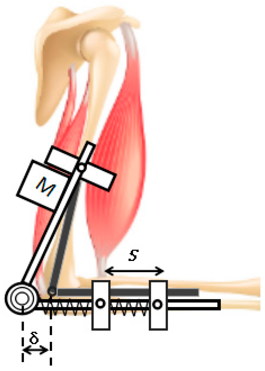
Figure 4.
Hand mechanical structure. (a) four-finger training module; (b) slider–crank mechanism.

Figure 5.
Thumb training module.
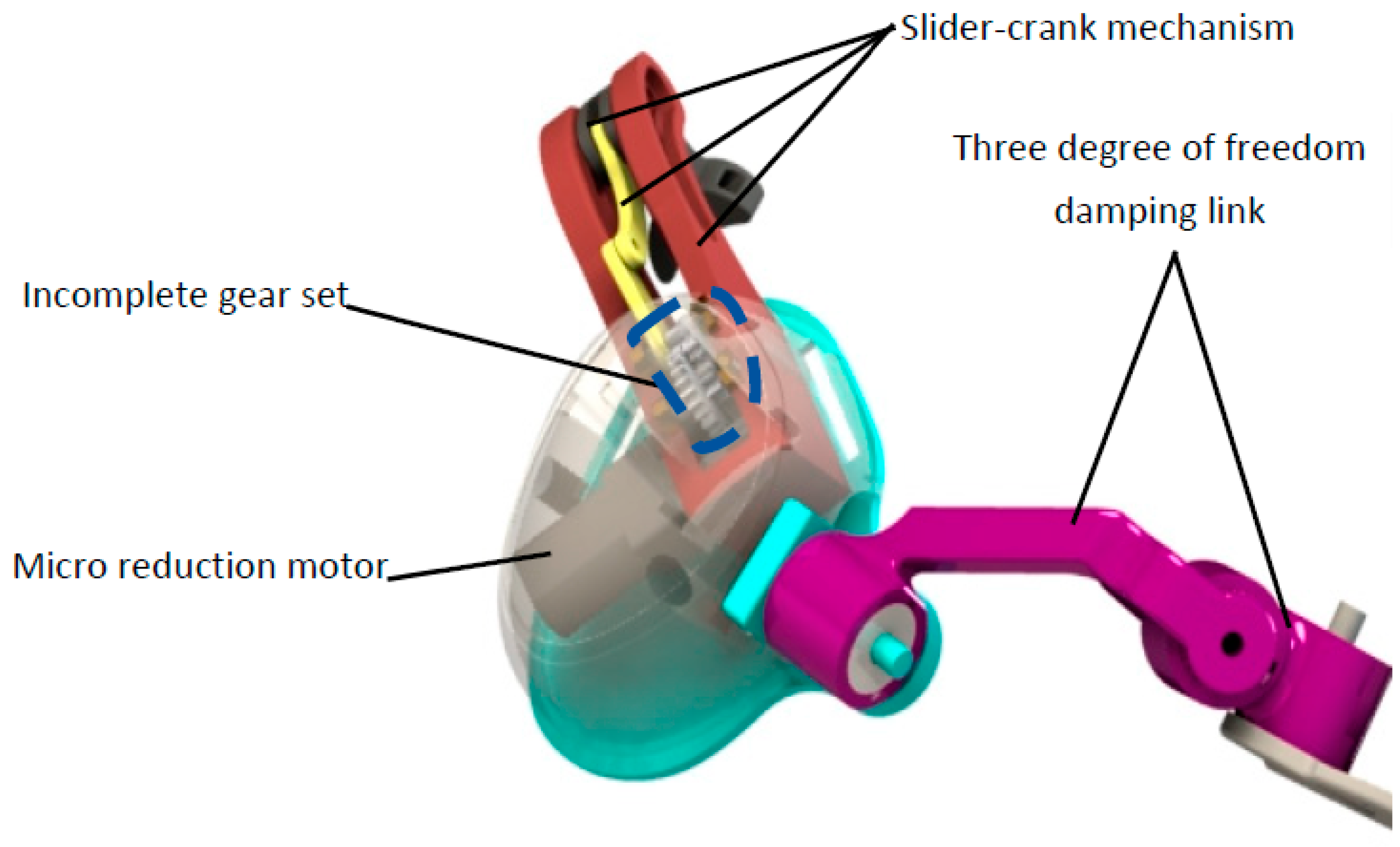
Figure 6.
Angular displacement curve of elbow joint.
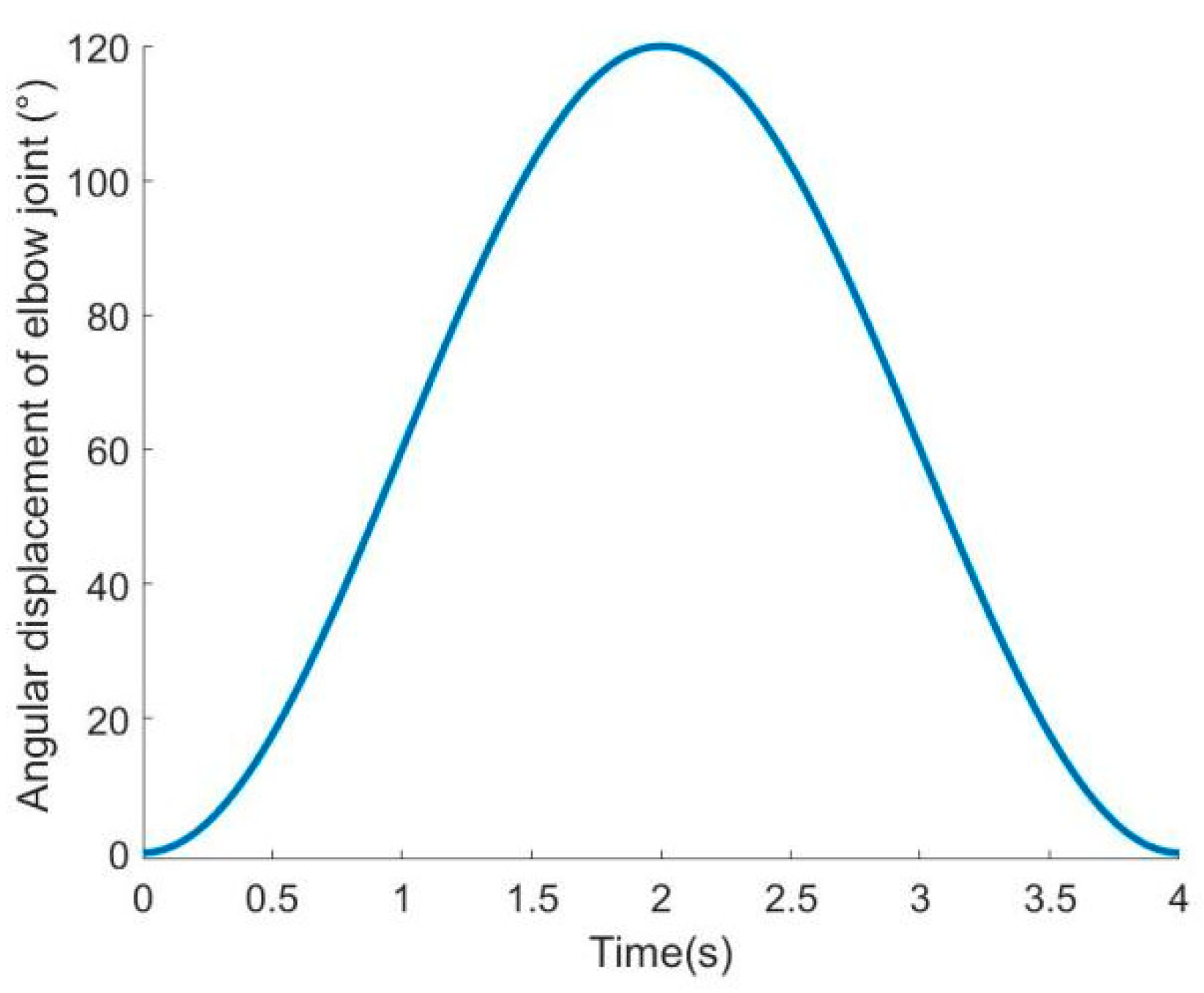
Figure 7.
Linear displacement curve of metacarpophalangeal joint.

Figure 8.
Angular displacement curve of each joint of hand.
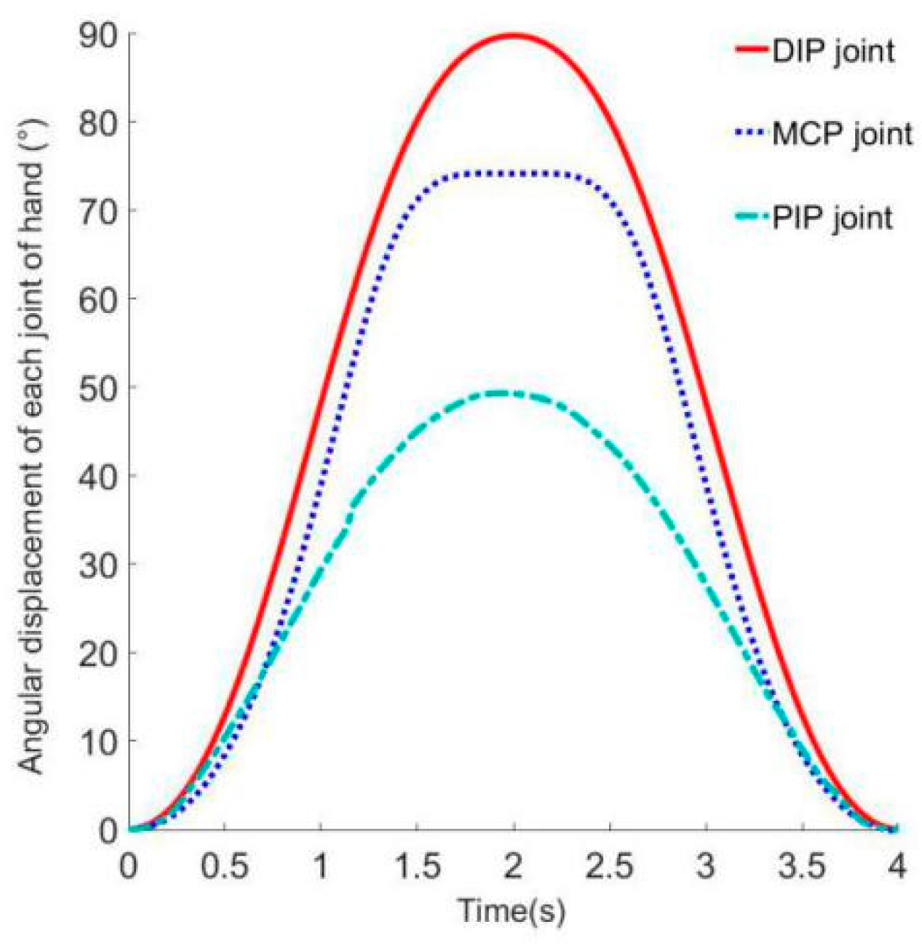
Figure 9.
Workspace Analysis: (a) schematic diagram of endpoints; (b) trainer workspace.

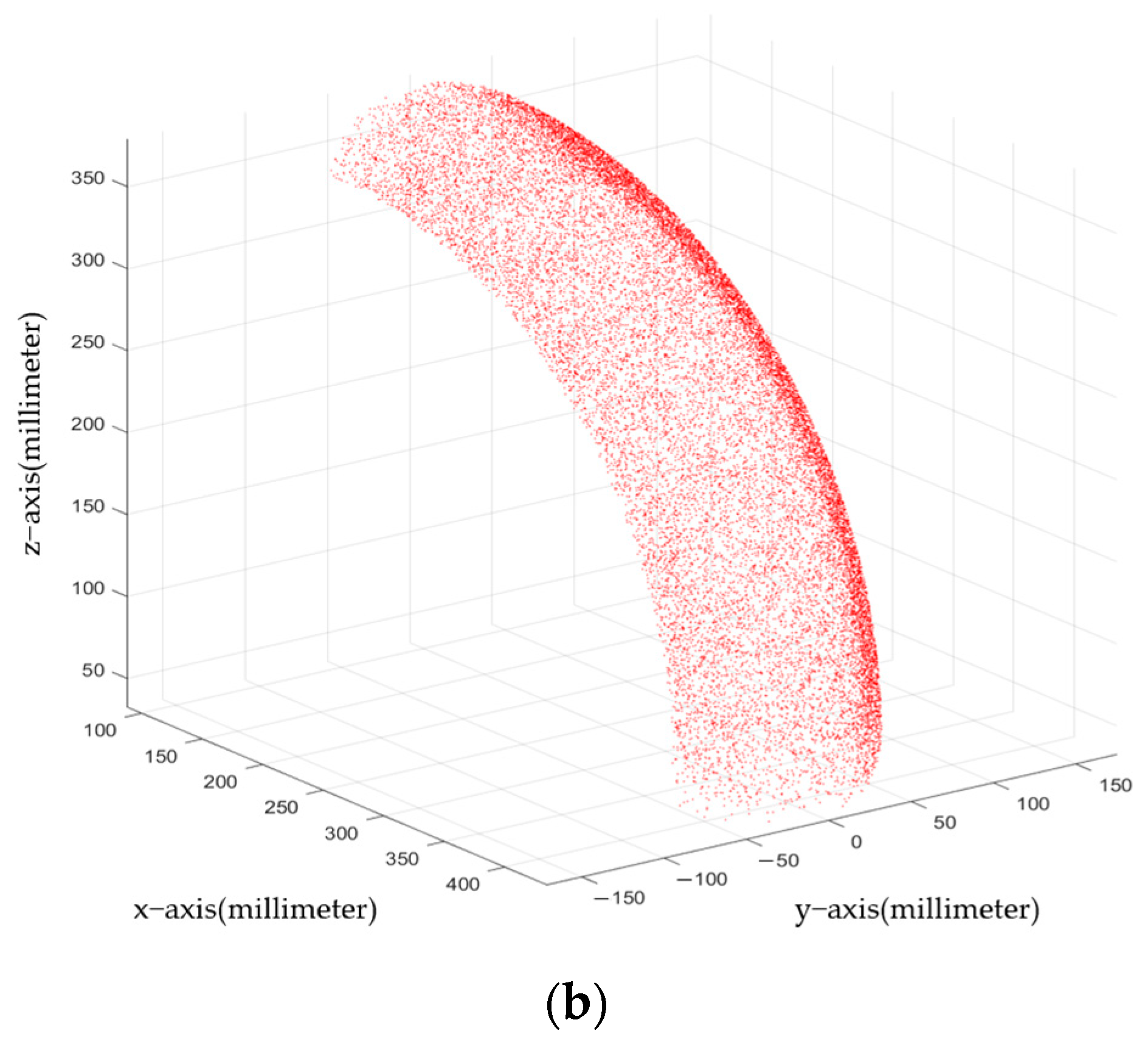
Figure 10.
Participant 1 tests the diagram: (a) measurement of elbow joint angle; (b) angle measurement of index finger joint; (c) angle measurement of interphalangeal joint of thumb.
Figure 10.
Participant 1 tests the diagram: (a) measurement of elbow joint angle; (b) angle measurement of index finger joint; (c) angle measurement of interphalangeal joint of thumb.
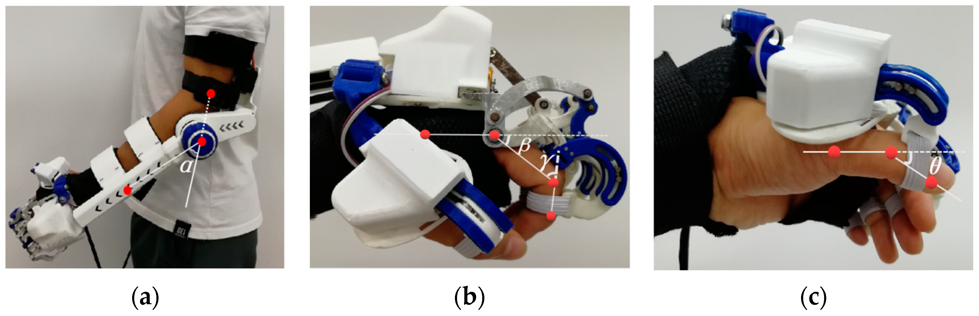
Figure 11.
Participant 2 tests the diagram: (a) measurement of elbow joint angle; (b) measurement of hand joint angles.
Figure 11.
Participant 2 tests the diagram: (a) measurement of elbow joint angle; (b) measurement of hand joint angles.

Figure 12.
Grasp strength test platform: (a) schematic diagram of test platform; (b) tension test prototype.
Figure 12.
Grasp strength test platform: (a) schematic diagram of test platform; (b) tension test prototype.

Figure 13.
Grasp test 1: (a) grasp pen; (b) grasp card; (c) grasp book; (d) grasp water cup; (e) grasp apples; (f) grasp paper towels; (g) grasp bottled drinking water.
Figure 13.
Grasp test 1: (a) grasp pen; (b) grasp card; (c) grasp book; (d) grasp water cup; (e) grasp apples; (f) grasp paper towels; (g) grasp bottled drinking water.
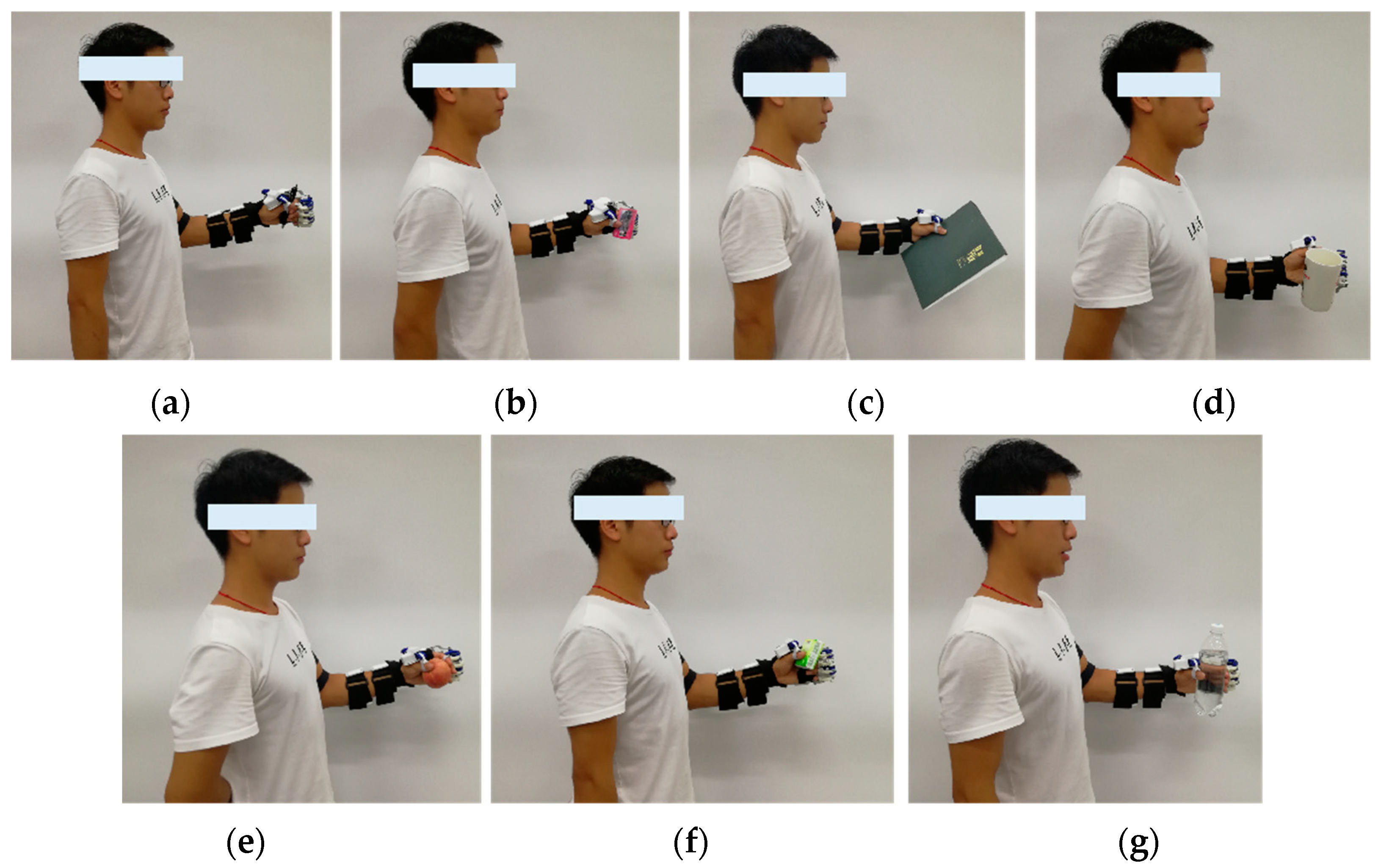
Figure 14.
Grasp test 2.
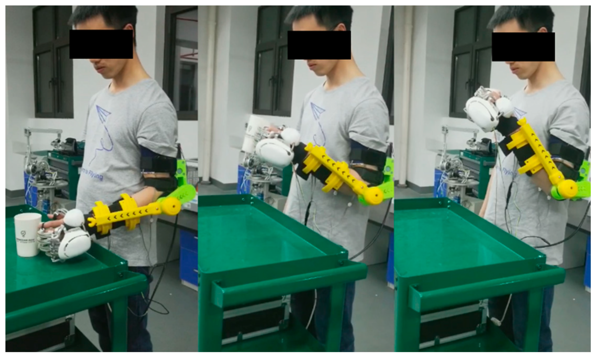
Figure 15.
Grasp test 3: (a) Participant 4; (b) grasping the pen; (c) Participant 5; (d) grasping the tissue box; (e) Participant 6; (f) grasping the water cup.
Figure 15.
Grasp test 3: (a) Participant 4; (b) grasping the pen; (c) Participant 5; (d) grasping the tissue box; (e) Participant 6; (f) grasping the water cup.

Table 1.
Mechanical parameters of exoskeleton.
| Joint | Angular Range (°) | Healthy Human Joint Range (°) |
|---|---|---|
| Elbow Joint | Flexion/Extension 0–120 | Flexion/Extension 0–135 |
| Four-Finger MCP | Flexion 0–84 | Flexion 0–90 |
| Four-Finger PIP | Flexion 0–73 | Flexion 0–110 |
| Thumb IP | Flexion 0–49 | Flexion 0–70 |
Table 2.
Participant body data.
| ID | Gender | Age | Height | Weight |
|---|---|---|---|---|
| 1 | Male | 24 | 175 cm | 60 kg |
| 2 | Male | 25 | 177 cm | 65 kg |
| 3 | Male | 26 | 175 cm | 58 kg |
| 4 | Female | 43 | 162 cm | 62 kg |
| 5 | Female | 25 | 158 cm | 42 kg |
| 6 | Male | 27 | 170 cm | 71 kg |
Table 3.
Range of motion of each joint of Participant 1.
| Angle | 1 | 2 | 3 | 4 | 5 | Average Value |
|---|---|---|---|---|---|---|
| α | 114.6 | 114.9 | 115.5 | 115.3 | 115.7 | 115.2 |
| β | 76.2 | 76.0 | 75.8 | 75.4 | 75.7 | 75.8 |
| γ | 71.9 | 71.5 | 72.2 | 71.4 | 71.7 | 71.7 |
| θ | 37.5 | 37.8 | 38.1 | 38.2 | 37.9 | 37.9 |
Table 4.
Range of motion of each joint of Participant 2.
| Angle | 1 | 2 | 3 | 4 | 5 | Average Value |
|---|---|---|---|---|---|---|
| α | 115.3 | 114.7 | 114.4 | 115.6 | 115.0 | 115.0 |
| β | 75.5 | 76.2 | 76.0 | 75.6 | 75.5 | 75.7 |
| γ | 71.1 | 71.4 | 72.3 | 71.6 | 71.5 | 71.5 |
| θ | 37.7 | 37.6 | 38.0 | 38.2 | 38.5 | 38.0 |
Disclaimer/Publisher’s Note: The statements, opinions and data contained in all publications are solely those of the individual author(s) and contributor(s) and not of MDPI and/or the editor(s). MDPI and/or the editor(s) disclaim responsibility for any injury to people or property resulting from any ideas, methods, instructions or products referred to in the content. |
© 2023 by the authors. Licensee MDPI, Basel, Switzerland. This article is an open access article distributed under the terms and conditions of the Creative Commons Attribution (CC BY) license (https://creativecommons.org/licenses/by/4.0/).
Share and Cite
MDPI and ACS Style
Meng, Q.; Liu, G.; Meng, Q.; Xu, X.; Qin, L.; Yu, H. Bionic Design of a Novel Portable Hand-Elbow Coordinate Exoskeleton for Activities of Daily Living. Electronics 2023, 12, 3326. https://doi.org/10.3390/electronics12153326
AMA Style
Meng Q, Liu G, Meng Q, Xu X, Qin L, Yu H. Bionic Design of a Novel Portable Hand-Elbow Coordinate Exoskeleton for Activities of Daily Living. Electronics. 2023; 12(15):3326. https://doi.org/10.3390/electronics12153326
Chicago/Turabian StyleMeng, Qingyun, Guanxin Liu, Qiaoling Meng, Xin Xu, Liang Qin, and Hongliu Yu. 2023. "Bionic Design of a Novel Portable Hand-Elbow Coordinate Exoskeleton for Activities of Daily Living" Electronics 12, no. 15: 3326. https://doi.org/10.3390/electronics12153326
Note that from the first issue of 2016, this journal uses article numbers instead of page numbers. See further details here.