
Development of a Compliant Lower-Limb Rehabilitation Robot Using Underactuated Mechanism

1
State Key Laboratory of Robotics and System, Harbin Institute of Technology, Harbin 150001, China
2
Department of Mechanical Engineering, Harbin Institute of Technology (Weihai), Weihai 264209, China
3
Tianzhi Institute of Innovation and Technology, Weihai 264209, China
*
Author to whom correspondence should be addressed.
Electronics 2023, 12(16), 3436; https://doi.org/10.3390/electronics12163436
Submission received: 28 June 2023
/
Revised: 3 August 2023
/
Accepted: 10 August 2023
/
Published: 14 August 2023
(This article belongs to the Special Issue Advanced Wearable/Flexible Devices and Systems in Bioelectronics)
Abstract
:Most existing lower-limb rehabilitation robots (LLRR) for stroke and postoperative rehabilitation are bulky and prone to misalignments between robot and human joints. These drawbacks hamper LLRR application, leading to poor arthro-kinematic compatibility. To address these challenges, this paper proposes a novel robot with portability and compliance features. The developed robot consists of an underactuated mechanism and a crus linkage, respectively corresponding to the hip and knee joints. The underactuated mechanism is a new type of remote center of motion (RCM) mechanism with two sets of contractible slider cranks that can reduce the misalignments between robot and human joints. The underactuated mechanism is then optimized using the particle swarm optimization method, and the developed robot’s kinematic analysis is presented. The proposed robot can be simplified as a two-link mechanism with the ability to easily plan its trajectory using the modified Denavit–Hartenberg method. Finally, passive exercise trials demonstrate that the mismatch angles between the human and robot knee joints are less than 2.1% of the range of motion, confirming the feasibility and effectiveness of the proposed robot.
1. Introduction
The increasing population ages and traffic accidents have led to a substantial demand for lower-limb rehabilitation, particularly after knee arthroplasty (knee arthroplasty (KA)) [1,2], lower-limb hemiplegia [3,4], and other lower-limb orthopedic surgeries. However, the shortage of skilled therapists has caused unfavorable outcomes following orthopedic surgery or stroke. In this case, the development of lower-limb rehabilitation robots (LLRR) has offered solutions by enabling extensive rehabilitation exercises with good consistency [5,6]. LLRR have been developed for decades with the aims of improving rehabilitation outcomes and reducing the workload of therapists, which is crucial for rehabilitation in orthopedic surgery, gait rehabilitation [7,8,9], and muscle strength training [6,10].
There exist two major categories of LLRR, lower-limb exoskeletons (LLEs) [11,12] and end-effector-based robots [13]. The advantages of the LLEs compared to end-effector-based robots are the multijoint motions, limb weight support [4], and high safety [14,15]. Moreover, the sitting/lying-type LLEs provide convenience to treat lower-limb impairment patients during the initial stages of rehabilitation training, as the patients have no autonomous movement abilities [11]. Previous designs of the sitting/lying-type LLRR have mainly focused on achieving the flexion–extension movement of the hip/knee on the sagittal plane. Wang et al. [12] designed a 3-DOF sitting/lying-type LLRR equipped with eccentric slider-crank mechanisms, showing good potential in rehabilitation exercises. Unfortunately, this robot ignored the potential impact of joint misalignment, which may result in spurious forces and torques. Vaida et al. [16,17] designed a parallel rehabilitation robot that enables a patient to perform lower-limb rehabilitation on the bed, targeting the acute stroke phase. This robot consists of two modules with 4-DOF and eight motors, enabling rehabilitation exercises for all three joints; however, the volume limits maneuverability. Wang et al. [18] developed a 4-DOF workspace LLRR that covers the flexion/extension of three lower-limb joints and adduction/abduction of the hip joint. It allows patients to directly perform rehabilitation training in a wheelchair. However, this robot belongs to the end-effector, and a direct push force exerted on the foot could result in an excessive internal force on the knee joint and discomfort for patients [19]. Mohan et al. [20] designed a 2PRP-2PPR planar parallel orthosis named ANKUR-LL II which can provide a sitting/lying arrangement, consisting of a 3-DOF active manipulator and a passive exoskeleton based on a 3R serial chain. A compound gear train is deployed in this robot to amplify the rotation angle at the end-effector; however, the mechanical structure limits mobility for home-based rehabilitation. Barbosa et al. [21] proposed a low-cost and cable-driven parallel LLRR that can help with gait rehabilitation. The mechanical structure of this robot is easy to assemble, but the cable actuation requires a complex control design and a large volume.
Although the aforementioned LLRR can provide multijoint rehabilitation motions for lower limbs, several challenges remain. The first challenge for the design of the LLRR is to decrease the misalignments between the robot and human joints. A previous study [22] has demonstrated that the misalignments of the hip joint center can reduce the range of motion (ROM) of the knee during continuous passive motion (CPM) [23] and enlarge the misalignment at the knee joint, as shown in Figure 1d. Standing/walking LLRR with compliant components and self-aligning mechanisms have been widely used [24,25,26], while most sitting/lying LLRR lack compliant design, increasing misalignments and load between the knee and the robot [27,28]. In addition, these LLRR are restricted to a laboratory setting with large space due to their size and weight [29]. Their use for home-based rehabilitation [30], which can reduce the financial costs and length of hospital stays for patients [31], is hampered by the bulky structures and low mobility. Finally, most of these LLRR were designed for patients after stroke, while few were for patients after KA. Although pneumatic actuation [32,33] applied in CPM devices could improve safety and comfort, these pneumatic CPM devices can only conduct flexion–extension movement of the knee. Thus, it is still a challenge to design a portable and compliant LLRR with multiple exercises for patients after orthopedic surgery or stroke, especially in outpatient and home settings.
To address these challenges, a novel anthropomorphic LLRR has been developed, obtaining the benefits of portability, compliance, and affordability. This robot consists of an underactuated five-bar mechanism corresponding to the hip joint and two sets of links corresponding to the knee and ankle. The design of the proposed robot aims at addressing the following concerns of existing designs: (a) the lack of kinematic structures compatible with the human anatomy causing misalignments between the joints of robots and humans; (b) the large size and weight hindering the application of home-based rehabilitation [12,18]; and (c) complex structures with high inertia causing undesirable difficulties for control [20,34,35]. Considering the recommended rehabilitation exercises for patients after stroke and knee surgery, as shown in Figure 1, the movement of the hip joint and thigh is mainly in the sagittal plane. Therefore, based on the remote center of motion (RCM) mechanism, a 3-DOF underactuated five-bar linkage was designed to match the hip joint, which can significantly reduce the mechanism’s weight and inertia. An underactuated mechanical system can reduce the use of actuators and energy consumption, which has been widely applied in spacecraft, robotics and underactuated manipulators [36]. The proposed RCM mechanism based on the five-bar linkage using contractible slider cranks offers the advantages of a relatively low risk of interference and foldable structure, although numerous types of RCM mechanisms have been proposed previously [37,38,39]. Furthermore, to improve the portability of the device, it is necessary to optimize the size of the mechanism through an optimization algorithm. Since the optimization of the underactuated five-bar linkage is a nonlinear problem, the particle swarm optimization (PSO) method [12,40] is used to optimize the link length and slider stroke.
This paper is organized as follows. Section 2 presents the synthesis and static analysis of the robot, including the underactuated mechanism design, mechanical structure optimization, and compliant passive DOF design. Kinematic analysis is then presented in Section 3. Section 4 introduces the passive exercise trials to investigate the performance of the robot, and the results are then discussed. Finally, Section 6 concludes this work.
2. Proposed Robot Design
This section describes the details of the novel LLRR’s conceptual design and structure optimization. The robot was developed for home-based rehabilitation and patients with a height of 1600~1850 mm. Given the recommended rehabilitation exercises in Figure 1, the angle range for each joint is shown in Table 1. Since the knee and ankle joint mechanisms of the proposed robot is relatively simple, the synthesis and optimization are formulated by focusing on the hip joint mechanism.
2.1. Recording of the Human Hip Trajectory
Hip joint and thigh segment trajectories during rehabilitation exercises play an important role in the design of a robot that mimics natural hip flexion and extension for individuals after stroke or knee surgery. Thus, to characterize the motions of the lower limb, the trajectory of the lower limb of a healthy subject was recorded using a motion capture system with eight cameras (Mars2H, Nokov, Beijing, China, sampling rate 50 Hz). Both markers attached to anatomical landmarks and clusters of markers on rigid plates were placed according to a modified Helen Hayes set [41], as depicted in Figure 2a. Markers were placed on the pelvis, thigh, knee, shank, and ankle. The subjects were asked to carry out the rehabilitation exercises motions (see Figure 1) ten times.
The results show that the trajectory of marker A (greater trochanter) follows a linear trajectory, while the trajectory of marker B (lateral epicondyles of the femur) falls in circular arcs (Figure 2b). Although it is difficult to predict the true center of rotation (COR) of the hip joint, least-squares fitting can be used to determine the COR and radius of marker B. Therefore, the thigh can be rotated by the RCM mechanism that supports circular motions for the hip joint.
2.2. Underactuated Mechanism Design
Details of the virtual prototype of the proposed robot are depicted in Figure 3. The robot consists of three modules, namely, hip, knee, and ankle joint mechanisms. In this study, to endow the LLRR with good compatible performance while ensuring small size and low inertia, an underactuated five-bar linkage based on a double slider-crank mechanism was developed. Moreover, the affordability of LLRR for outpatient and home settings is another objective of this novel design. The proposed robot is mainly made of aluminum alloy pipes and plastic, to reduce the weight. Figure 3b shows the exploded view for the underactuated mechanism, especially the joint unit B, C and D. Joint B and C has the same mechanical components, consisting of bearing and customized spring units. It should be pointed out that link 4 is connected with link 3 through a passive revolute on the seal cover of the motor housing. The electric putter is comprised of a high-performance 24 V step motor (AZM46MK, Oriental motor, Tokyo, Japan), a gearbox with a 100:1 reduction ratio, and an electric cylinder with a stroke of 30 mm. The actuation units of motors 1 and 2 are the same, while the stroke of slider E is 70 mm. The motor of joint D does not belong to the underactuated mechanism, indicating that the actuation units of the underactuated mechanism only include motors 1 and 2.
A new RCM mechanism taking the requirement for compatibility into account and reducing the risk of interference with the lower limb was designed. In contrast to conventional parallelogram-based RCM mechanisms, an underactuated five-bar linkage RCM mechanism with a slider and an electric putter is proposed. Actuators for the slider and electric putter mechanism are positioned on the base to match the hip center for different thigh lengths and reduce the inertia of the five-bar mechanism. The movable slider is fixed on the nut of a lead screw, and link 1 is connected to the electric putter. To improve the stability of joints B1 and B2 (see Figure 3), the two joints are connected by link B1B2, and two linear slides are used as support. This design reduces the force of the electric push rod (link 1) in the vertical direction and makes its movement more stable. The DOF of the five-bar linkage is given by the Chebyshev–Grübler–Kutzbach criterion:
where n is the total number of links (including the ground link), and f1 is the number of joints. In the presented robot, the five-bar linkage (ABCDE) has 6 binary links and 6 first-order joints. Accordingly, the presented five-bar linkage possesses 3 DOFs. Figure 3 shows that there are only two inputs (motors 1 and 2); thus, the five-bar linkage (ABCDE) mechanism is underactuated.
As shown in Figure 4a, the customized torsional springs at joints B1/B2 and C1/C2 (see Figure 3) ensure that θC and θB remain in a desired pose under the gravity of the lower limb. In addition, mechanical limit stops are designed to prevent excessive hyperextension of joints B and C. In this context, the joints connected to actuators are defined as actuated joints, while those connected to torsional spring are defined as passively driven joints (B and C joints, Figure 4a). Furthermore, joint D and rotational joint E are defined as passive joints that are free to move. It should be noted that joint E has two DOFs (double joint); one is a translational pair and the other is a rotational pair. In the five-bar linkage (ABCDE), joint D is a passive rotating joint, while it is an actuated joint due to motor 3 in the crus link.
2.3. Motion Principle of the Underactuated Mechanism Design
As recommended by therapists, the designed underactuated hip joint mechanism moves slowly. Meanwhile, inertial forces are negligible when compared to lower-limb gravity and external forces exerted by motors. As a result, the dynamic of this system is not taken into account, and a static model is adequate to describe how the underactuated five-bar mechanism rotates the thigh. The purpose of the static analysis is to estimate the torsion spring torque for the five-bar linkage to maintain a balanced configuration. A generic equilibrium configuration of the five-bar linkage can be easily obtained when it is static without any external load, as shown in Figure 4b. Taking links l2 and l3 together as the investigated object, one can obtain:
where M0, MD0, and MCg are moments generated by G0 (equivalent gravity of the link structure and motor 3), FD0, and GC (equivalent gravity exerted on joint C), respectively. MBs is the torsion torque of the torsional spring located at joint B, while MCs is the torsion torque at joint C. Furthermore, kB and kC are the stiffness coefficients of spring B and C, respectively. θB0 and θC0 are the initial angles of joints B and C. Note that the ROM of joints B and C are restricted by mechanical limits as follows: joint B, relative to the base, θB = 110° to 170°; joint C, relative to link l2, θC = 30° to 150°. Anticlockwise rotation is considered as the positive direction. Due to the existence of MBs, MCs, and the preload force (FE0 and FA0) of joints A/E caused by mechanical restriction, the five-bar linkage can remain in a stable configuration.
The gravity of a lower limb restricts the movement of the five-bar linkage when the leg is attached to links l3 and l6. The movement trajectory of the thigh (see Figure 2) forms a constraint on the movement of link l3, which is referred to as an external constraint. The forces exerted by joints E and A, spring torsion, gravity, and external constraint work together to keep the five-bar linkage in a required configuration. The torque MD generated by the actuation force FE is applied to link l3 via link l4, as shown in Figure 5. Similarly, torque MA generated by the actuation force FA is applied to link l2. For a better understanding of the motion principle of the five-bar linkage, a quasi-static equilibrium about joints B and C is obtained, as shown in Figure 5.
Taking the anticlockwise rotation of link l3 as an example (Figure 5a), one can obtain
where M1 and MC1 are moments generated by G1 (equivalent gravity of the lower limb and link structure) and GC1 (equivalent gravity exerted on joint C). MD1 and MA1 are moments generated by FD1 and FA1, respectively. As the variation of MBs is nonlinear, the stiffness coefficients kB and kC are determined through trial–error experiments. In joint B, MBs is exerted by the torsion spring to maintain clockwise rotation for link l2. Mechanical limits are designed to limit θB from 110° to 170° under the action of MBs when external forces are applied on joints B and C. Details of the motion sequence for the five-bar linkage are shown in Figure 6.
Figure 6a,b illustrate the motion principle of the hip joint mechanism (underactuated five-bar linkage). It should be noted that this sequence occurs while the actuators continuously move to the left. In Figure 6a, link l3 on joint D is rotated counterclockwise as the actuated joint E moves from the initial position E1 to E2, and joint C acts as a rotating base. When the thigh is strapped to link l3 through belts, the hip joint O acts as a virtual base. Thus, the proposed five-bar mechanism can be considered as a series of two consecutive three-bar slider-crank linkage mechanisms EDO and BCO, as shown in Figure 6c,d. Figure 6c shows that the distance r2 decreases along the x-axis as the actuated joint E moves by a small displacement ∆r2 (leftward movement), inducing a small angular displacement (∆2) between the thigh and l3. Therefore, the thigh gravity exerted on joint C will decrease considerably. Due to the effect of MBs, joint C will be stuck by the thigh when the passively driven joint B shifts to the left by a small displacement ∆r1 (leftward movement), as shown in Figure 6d. Joints C and D can fit a circular trajectory by changing the pose of the link CD through the special sequence motion of joints E and A. Therefore, the position of the virtual base point O can be changed to adapt the mechanism to different thigh lengths. Various parameters such as the pose of link CD and the values of θB and θC can be obtained by the inertial sensor and potentiometer. These parameters enable the system to achieve closed-loop control and adjust the pose of link CD by adjusting the displacement of joints E and B. Finally, the estimation of kinematic compatibility [24,42] for the hip joint mechanism can be obtained by collecting misalignment between the thigh and link CD. For these reasons, the proposed five-bar linkage mechanism has the characteristics of the RCM mechanism, low inertia and underactuation, which can also adapt to patients with different heights.
2.4. Optimization of the Underactuated Mechanism
The purpose of optimizing the hip joint mechanism is to reduce its size. Figure 7 shows the schematic plot of the hip joint mechanism, which consists of two actuated joints at points E and A (prismatic pairs), two passively driven joints at points B and C, and passive joints D and E (revolution pairs), respectively. Since the proposed five-bar linkage is a kind of RCM mechanism, the sliding of A/E joints can adapt to different thigh lengths.
Therefore, the main objective of mechanism optimization is the stroke l1 of the electric putter and the stroke l5 of the slider E. The length of link CD (l3) is set to 200 mm by comparing it with other existing devices and thigh lengths. Depending on the range of leg length and the ROM of hip and knee joints listed in Table 1, the lengths of l2 and l4 links can be determined. The crus link l6 is designed to be retractable. It should be noted that the link structure l4 is designed to be v-shaped to avoid collision with link l6, as shown in Figure 3. Therefore, the length of l4 should ensure the following conditions:
The recommended values of thigh (lOD = l3 + l7) and knee height (l6) are as follows:
The limit positions of the hip joint mechanism are shown in Figure 7, and virtual joint O corresponds to the hip joint. Due to the limitation of the robot base and range of θB, the minimum value of the hip joint is 20° (ΨH2 = 20°). Considering the 50th percentile of sitting thigh thickness parameters [43] and design convenience, the height of the virtual rotation center is set to 60 mm (h1). The height of the center of joint B is designed as h2 = 40 mm, and the height of joint E is h3 = 80 mm. The value of l4 can be determined according to Equations (12) and (13), while the maximum value of l1 can be determined according to the vector-loop equation obtained from Figure 7a, as follows:
In the x and y directions, one can obtain:
where 110° ≤ θB1 ≤ 170°, the following constraint for l2 can be obtained by substituting Equation (13) into Equation (15):
The minimum of l1 when ΨH2 = 20° can be determined according to the vector-loop equation obtained from Figure 7b as:
Similarly, constraint equations in the x and y directions can be respectively obtained as:
The maximum value of l2 can be determined according to Equations (19) and (13). Thus, the range of l2 can be obtained as the first constraint:
Since , the total length of the allowable electric putter stroke l1 can be obtained by subtracting Equations (20) and (16), which is considered as the second constraint:
In the same way, the vector-loop equations obtained from the equivalent mechanism EDO are:
Therefore, the following constraint for l4 in the left and right limit positions can be obtained in the y direction, respectively, as:
Considering the range of θB, let θE ∈ [110°, 170°], the following constraint for l4 can be obtained by substituting Equation (13) into Equations (25) and (26):
In the x direction, the components of Equations (23) and (24) can be described by:
By subtracting Equation (28) from Equation (29), the range of the lead screw stroke (l5) can be obtained as:
It can be inferred from Equations (30) and (27) that l5 is positively correlated with l4, while Equations (16) and (20) indicate that l2 has a nonlinear inverse relationship with l1. Therefore, the minimum values of l4 and l5 can be determined. To make the size of the five-bar mechanism as small as possible and by considering Equations (13), (21) and (22), the following are the design variables with their ranges, the objective function, and the constraints:
Design vector:
Objective function to be minimized:
Constraints to be satisfied:
Since l2 has a nonlinear inverse relationship with l1, the PSO algorithm was applied to obtain the optimal length of linkages for the proposed five-bar linkage. By moving a swarm of particles across a multidimensional search space, the PSO algorithm searches for optima. For the PSO algorithm used in the present work, the number of particles and their dimensions are presented as N and d, respectively. The particles are updated according to the following equations.
where j denotes the particle, and i is the present iteration number. Vj(i+1) denotes a new velocity for each particle based on its previous velocity Vj(i), Pbest,j denotes the best location it has achieved so far, and Gbest,j denotes the global best location. The individual particle’s position Xj(i+1) is updated in solution hyperspace based on Equation (34). The parameters c1 and c2 in Equation (35) are the cognition and social acceleration coefficients, respectively. For the j-th particle, r1 and r2 are the two random numbers that were separately created in the [0, 1] range. The inertia weight factor is denoted as wi, which plays an important role in the PSO convergence behavior and can be defined as:
where wmin denotes the minimal value of inertia weight and n is the maximum number of iterations. The maximum number of iterations is determined to be the number of generations necessary to attain the best value of the objective function.
To obtain the minimum value of the objective function, the j-th particle can be set as:
Since the values of the elements of Xj and Vj are constrained to the same ranges as l2, l7, and θB in Equation (31), respectively, the initial values of elements of Xj and Vj are given by:
where and are the upper bound and lower bound of the search space for the j-th dimension, and is a random number generated in the range [0, 1]. After a certain number of generations, the values of the objective function remain unchanged. Following various trials, the optimization parameters for the PSO algorithm are obtained as follows:
- (1)
- maximum number of generations: 200;
- (2)
- population: 50;
- (3)
- minimum of the inertia weight (wmin): 0.4;
- (4)
- c1 and c2: 2.
The design employs a small-size solution, selecting l2 = 270 mm and l1 = 228 mm. To consider the variation of h1 caused by body weight and improve adaptive alignment performance, l1 is designed as 280 mm to improve the flexibility of the five-bar linkage. Finally, the length and width of the robot are designed to be 910 mm and 300 mm, respectively. The mechanical structure and compliant design comparison with the other sitting/lying LLRR are shown in Table 2, which indicates that the proposed robot is portable for outpatient and home settings. The total mass of the prototype robot is 11.8 kg, including the actuators and the electric putter, which makes it portable for outpatient and home settings.
2.5. Knee and Ankle Joint Mechanisms
The knee and ankle joint mechanism model composed of crus link 1 and crus link 2 is shown in Figure 8. The length of connecting link 2 can be adjusted to different calf lengths. Motor module 3 consists of a DC servo motor and a harmonic reducer. This motor module directly drives crus link 1 to complete the rotation of the knee joint mechanism. The knee joint mechanism could induce a slight movement of the sagittal plane and tibia rotation accompanied by skin deformations [19,44]. These deformations occurring at the interface between the leg and the robot might cause uncontrollable forces. Therefore, passive mechanisms were added to the crus bracket and support plate to avoid the appearance of undesired forces [45].
The crus bracket can slide and rotate along axis x1 on the slide rail, with a range of translation of ±20 mm and rotation of ±20° (α1). The restraint of the elastic rope restricts the rotation of the crus bracket around the slide rail. The crus bracket and support plate are made of resin by 3D printing. The translation of the support plate is achieved using linear sliding bearings and springs installed in the U-shaped support. The springs between the support plate and U-shaped support introduce the damping force and elasticity for translation along axis x1 and rotation of the ankle around axis y1. The rotation of the ankle joint is designed as passive DOF, and the ROM for the ankle around axis y1 is shown in Table 1. Thus, the designed passive mechanisms include two passive DOFs to cope with potential uncontrollable forces induced by skin deformations. Both the knee joint and the ankle joint mechanisms are treated as one link for simplicity, and the rehabilitation exercise of the lower limb in the sagittal plane can be achieved by considering the proposed robot as a two-link mechanism. The kinematic details of the proposed robot will be addressed in the following section.
3. Kinematic Analysis
In this section, a kinematic analysis of the designed rehabilitation robot is conducted to plan the robot’s trajectory, especially the hip joint mechanism. The robot is designed for passive and active lower-limb rehabilitation and can be considered as a two-link mechanism consisting of hip and crus links. The motion of the hip mechanism (five-bar linkage) is provided with two equivalent sliders. Kinematic parameters for the hip joint mechanism and two equivalent three-bar slider-crank linkage mechanisms are graphically described in Figure 9. The global coordinate system is attached to the virtual point O, and represents the angle from the x-axis to links l7 and l8, respectively. Therefore, the loop-closure equations of the equivalent slider-crank BCO and EDO are described as follows:
where s1 and s2 are the slider offsets in the y direction from joints B and E to point O, while r1 and r2 are the distances in the x direction from joints B and E to point O, respectively. By taking the derivative and rearranging Equations (39) and (40), one can obtain:
where and are linear velocities of joints B and slider E, and the angular velocities of links l7 and l8 are and , respectively. Moreover, the Jacobian matrix can be described as:
The relationship between the input velocities and the output angular velocities can be derived from Equations (40)–(44), as follows:
where Jq R2×2 denotes a Jacobian matrix for the hip joint mechanism. Referring to Equations (45) and (46), the singularity configuration of the hip joint mechanism occurs when Jq = 0, and Equation (47) can be obtained:
Therefore, the hip mechanism singularity occurs when θB or θE = nπ (n = 0, 0.5, 1), namely, BC/DE and AB are collinear or perpendicular. To avoid the singular configuration of the hip joint mechanism, mechanical limits are designed to restrict the range of θB and θE. Considering the working principle of the hip joint mechanism, let ψ1 = ψ2 = ψ and , we can obtain:
As the values of l8, l7, θB, θE, and ψ can be directly measured, the relationship between v1 (linear velocity of joint B) and v2 (linear velocity of joint E) can be calculated from Equation (47). In addition, the angle and the angular velocity of the knee joint can be readily obtained by the encoder in motor 3.
In the early stage of rehabilitation, collecting joint angles of healthy lower limbs as a reference for passive motion planning will benefit the comfort and safety of rehabilitation. Therefore, a simple and reliable kinematic model is necessary to achieve mirror therapy and conventional rehabilitation therapy [46]. By fixing the ankle joint, the lower limb and the rehabilitation robot can be considered as a two-link mechanism. Figure 9d indicates the established coordinates of each link, and the modified Denavit–Hartenberg method (MD–H) is used to determine the kinematic features. The z-axis of all joints is aligned with the joint axis and perpendicular to the paper outward. The MD–H parameters of the equivalent two-link mechanism are given in Table 3. The forward kinematics of the equivalent two-link mechanism can be obtained as:
where L1 and L2 are the lengths of the thigh and crus, and θH and θK are the angles of hip and knee joints. O1, O2, and F represent the hip joint, knee joint, and endpoint, respectively. For notational ease, c1 = cos θH, c12 = cos (θH + θK), s1 = sin θH, and s12 = sin (θH + θK). Because the ROM of the robot hip joint is 20°~80°, θH has a unique solution under this condition. Combining the range of motion of the robot knee joint, the angles can be derived as:
Therefore, the inverse kinematics solution is unique and easily obtained in this work, which can be used in passive and active rehabilitation during motion control.
4. Experimental Protocol and Evaluation
4.1. Experimental Protocol
An experimental prototype of the proposed robot was developed according to the mechanical optimization described in previous sections. Three healthy subjects gave their informed consent to participate. Research related to this article was approved by the Laboratory Academic Committee of the State Key Laboratory of Robotics and System (Ref. No. 2022035). Their average height and mass were (mean ± SD) 171 ± 4.1 cm and 67 ± 3.6 kg, respectively. A series of passive experiments are conducted to just verify the effectiveness of this rehabilitation robot in terms of arthro-kinematic compatibility of the lower limb. These experiments consist of two typical rehabilitation exercises, i.e., knee flexion–extension and elevation of the extended leg according to Figure 1, which are selected as periodic trajectories for verification. Note that trajectory optimization is not within the scope of this paper.
The natural motion trajectories (without the robot) of three healthy subjects were recorded as reference using the motion capture system and map the reference trajectory to the joint space of the robot. In these tests, the subject joint angles are measured using the motion capture system. The corresponding joints angular of the robot are recorded by the motion capture system and potentiometer assembled in the robotic joint together, as shown in Figure 10a. To measure the human–robot interaction forces, two Flexiforce A301 sensors (Tekscan Inc., Norwood, MA, USA) are placed between a soft elastic strap of the robot and the human shank, as shown in Figure 10b. Considering that pressure measurements during the passive exercise are susceptible to being influenced by the initial preload of the fastening strap, the total initial preload measured by the sensors is set as roughly 1.5 N. The preload of the elastic strap was below the comfort limit of each subject. In this paper, we processed data and exported the results using Micro Cal Origin 2017 software.
4.2. Kinematics and Interaction Force
Mismatch angles and interaction forces between the robot and the lower limb are recorded during the selected passive rehabilitation exercise. Figure 11 shows angle-tracking results including two complete cycles in arthro-kinematic compatibility tests to illustrate the performance of the proposed robot. As shown in Figure 11a, the subjects experienced knee flexion–extension with a ROM of 30°~90° on the knee joint and 35°~78° on the hip joint. Mismatch angles at 90° and 78° positions (peak angles) between the robot joint and subject joint are less than 1.9° and 2.2° (i.e., 2.1% and 2.8% of the maximum angle) for the knee joint and hip joints, respectively. Figure 11b shows the measured angles at the hip joint during the elevation of the extended leg exercise for both the subject and the robot, with a ROM of 33°~65°. Since the knee joint remained straight during the elevation of the extended leg exercise, there was no need to measure the knee joint angles. The results show that the maximum mismatch angles at the 65° position are less than 1.6°, which is 2.4% of the maximum motion angle.
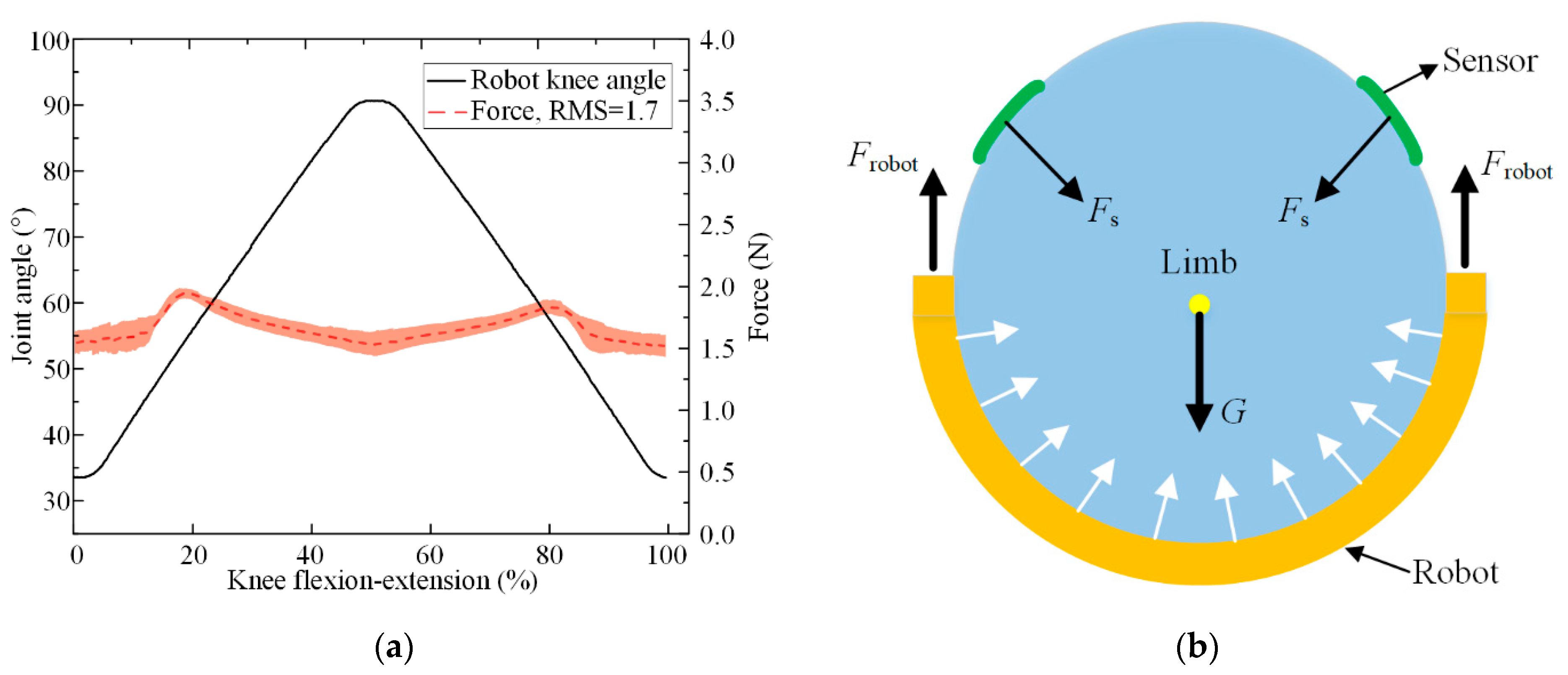
Figure 12 shows the measured interaction forces between the bandage and shank across all subjects and repetitions after time normalization based on knee flexion–extension sine-wave period. The average recorded interaction forces across all experiments varied from 1.55 N to 1.95 N. The shape of the interaction forces profile exhibits two local maxima at approximately 18% and 82% of knee flexion–extension cycles, showing limited variation from the initial preload. The low values of mismatch angles and interaction forces illustrate the kinematic compatibility of the robot mechanism.
5. Discussion
In previous LLRR designs, hip and knee mobility is simplified to a hinge joint. Rarely has a quantitative assessment of the kinematic compatibility between LLRR and the lower limb around the hip and knee been reported. To address the gap, a hip mechanism based on the RCM structure aiming at improving the kinematic compatibility of the LLRR has been designed, which is quantified by measuring the mismatch angles and interaction forces during the passive movements. Though the verification motions are passive, the results provide evidence of good kinematic compatibility in contrast to the CPM device. The mismatch angles occupying more than 20% of the ROM are reported between the human knee joint and the CPM device [22,23], which are much higher than our results (below 2.2%).
Previous powered exoskeletons and treadmill-based rehabilitation exoskeletons [24,28] focused on the self-aligning mechanism, which increases design complexity and mechanical impedance to some extent. Unlike previous research, we focused on mapping the human natural trajectory to the joint space of the robot by using the RCM mechanism. In addition, the passive auxiliary mechanism featured at the knee joint includes two passive DOFs of PR configuration, as shown in Figure 8, which reduces the false force and macro misalignments. These designs eventually lead to low interaction forces measured by the pressure sensors, which is in line with our expectations. Nevertheless, there might be room for improvement in some aspects of the proposed robot. In our future work, we will mount the force and joint torque sensors in each joint mechanism and develop assist-as-needed control based on motion intention. Due to the limited number of experiments at present, the future objective is to use machine learning after gathering enough samples to plan the optimal lower-limb motion trajectory.
6. Conclusions
A portable and compliant rehabilitation robot using an underactuated RCM mechanism was developed for postoperative and stroke patients to carry out rehabilitation exercises in both home-based and outpatient settings. The mechanical design, optimization, kinematic analysis, and experimental evaluation of this novel robot are carefully addressed. A novel compliant hip joint mechanism that consists of contractible slider cranks and stackable five-bar linkage was designed to achieve arthro-kinematic compatibility and low inertia for safe human–robot interaction. The length of the hip joint mechanism was optimized based on a PSO method due to its nonlinear characteristics. In the kinematic analysis, the robot is considered as a two-link mechanism to simplify its trajectory planning using the MD–H method. Additionally, passive mechanisms and compliant elements were added to the crus bracket to improve the compliance of the robot. Finally, passive rehabilitation exercise trials on healthy subjects with different heights were conducted to validate the kinematic compatibility of the proposed robot. The rehabilitation trajectory will be optimized and the control method will be further investigated to achieve active exercises in the future.
Author Contributions
Conceptualization, Y.Y. (Yunlong Yang) and Y.Y. (Yufeng Yao); methodology, Y.Y. (Yunlong Yang) and J.G.; software, Y.Y. (Yunlong Yang) and H.Y.; validation, Y.Y. (Yunlong Yang), Y.Y. (Yufeng Yao) and H.Y.; data analysis, Y.Y. (Yunlong Yang) and H.Y.; writing—original draft preparation, Y.Y. (Yunlong Yang) and J.G.; writing—review and editing, Y.Y. (Yunlong Yang), H.Y., Y.Y. (Yufeng Yao) and J.G.; funding acquisition, Y.Y. (Yufeng Yao). All authors have read and agreed to the published version of the manuscript.
Funding
This work is supported by the National Key R&D Program of China (Grants No. 2021YFB2011900 and No. 2018YFB1308100).
Institutional Review Board Statement
The study was conducted in accordance with the Declaration of Helsinki and approved by the Laboratory Academic Committee of the State Key Laboratory of Robotics and System, Harbin Institute of Technology (Ref. No. 2022035).
Informed Consent Statement
Informed consent was obtained from all subjects involved in the study.
Data Availability Statement
The data presented in this study are available on request from the corresponding author. The data are not publicly available due to privacy.
Conflicts of Interest
The authors declare no conflict of interest.
References
- Song, L.; Wang, A.; Zhong, J. Inverse Dynamics Modeling and Analysis of Healthy Human Data for Lower Limb Rehabilitation Robots. Electronics 2022, 11, 3848. [Google Scholar] [CrossRef]
- Preston, J.S.; KBateman, D.; Tria, A.J., Jr. Constraint in Revision Total Knee Arthroplasty. Mastering Orthop. Tech. Revis. Knee Arthop. 2019, 1, 1–7. [Google Scholar]
- Sarajchi, M.; Al-Hares, M.K.; Sirlantzis, K. Wearable Lower-Limb Exoskeleton for Children with Cerebral Palsy: A Systematic Review of Mechanical Design, Actuation Type, Control Strategy, and Clinical Evaluation. IEEE Trans. Neural Syst. Rehabil. Eng. 2021, 29, 2695–2720. [Google Scholar] [CrossRef] [PubMed]
- Sarajchi, M.; Sirlantzis, K. Design and Control of a Single-Leg Exoskeleton with Gravity Compensation for Children with Unilateral Cerebral Palsy. Sensors 2023, 23, 6103. [Google Scholar] [CrossRef] [PubMed]
- Susanto, S.; Simorangkir, I.T.; Analia, R.; Pamungkas, D.S.; Soebhakti, H.; Sani, A.; Caesarendra, W. Real-Time Identification of Knee Joint Walking Gait as Preliminary Signal for Developing Lower Limb Exoskeleton. Electronics 2021, 10, 2117. [Google Scholar] [CrossRef]
- Dupont, P.E.; Nelson, B.J.; Goldfarb, M.; Hannaford, B.; Menciassi, A.; O’Malley, M.K.; Simaan, N.; Valdastri, P.; Yang, G.-Z. A decade retrospective of medical robotics research from 2010 to 2020. Sci. Robot. 2021, 6, eabi8017. [Google Scholar] [CrossRef]
- Calabrò, R.S.; Billeri, L.; Andronaco, V.A.; Accorinti, M.; Milardi, D.; Cannavò, A.; Aliberti, E.; Militi, A.; Bramanti, P.; Naro, A. Walking on the Moon: A randomized clinical trial on the role of lower body positive pressure treadmill training in post-stroke gait impairment. J. Adv. Res. 2020, 21, 15–24. [Google Scholar] [CrossRef]
- Wang, D.; Lee, K.-M.; Ji, J. A passive gait-based weight-support lower extremity exoskeleton with compliant joints. IEEE Trans. Robot. 2016, 32, 933–942. [Google Scholar] [CrossRef]
- Duschau-Wicke, A.; Von Zitzewitz, J.; Caprez, A.; Lunenburger, L.; Riener, R. Path control: A method for patient-cooperative robot-aided gait rehabilitation. IEEE Trans. Neural Syst. Rehabil. Eng. 2009, 18, 38–48. [Google Scholar] [CrossRef] [Green Version]
- Qiu, S.; Pei, Z.; Wang, C.; Tang, Z. Systematic Review on Wearable Lower Extremity Robotic Exoskeletons for Assisted Locomotion. J. Bionic Eng. 2023, 20, 436–469. [Google Scholar] [CrossRef]
- Li, W.; Liu, K.; Li, C.; Sun, Z.; Liu, S.; Gu, J. Development and Evaluation of a Wearable Lower Limb Rehabilitation Robot. J. Bionic Eng. 2022, 19, 688–699. [Google Scholar] [CrossRef]
- Wang, W.; Hou, Z.-G.; Tong, L.; Zhang, F.; Chen, Y.; Tan, M. A novel leg orthosis for lower limb rehabilitation robots of the sitting/lying type. Mech. Mach. Theory 2014, 74, 337–353. [Google Scholar] [CrossRef]
- Komada, S.; Hashimoto, Y.; Okuyama, N.; Hisada, T.; Hirai, J. Development of a biofeedback therapeutic-exercise-supporting manipulator. IEEE Trans. Ind. Electron. 2009, 56, 3914–3920. [Google Scholar] [CrossRef]
- van Kammen, K.; Boonstra, A.M.; van der Woude, L.H.; Visscher, C.; Reinders-Messelink, H.A.; den Otter, R. Lokomat guided gait in hemiparetic stroke patients: The effects of training parameters on muscle activity and temporal symmetry. Disabil. Rehabil. 2020, 42, 2977–2985. [Google Scholar] [CrossRef] [Green Version]
- Jezernik, S.; Colombo, G.; Keller, T.; Frueh, H.; Morari, M. Robotic orthosis lokomat: A rehabilitation and research tool. Neuromodul. Technol. Neural Interface 2003, 6, 108–115. [Google Scholar] [CrossRef]
- Vaida, C.; Birlescu, I.; Pisla, A.; Ulinici, I.-M.; Tarnita, D.; Carbone, G.; Pisla, D. Systematic design of a parallel robotic system for lower limb rehabilitation. IEEE Access 2020, 8, 34522–34537. [Google Scholar] [CrossRef]
- Husty, M.; Birlescu, I.; Tucan, P.; Vaida, C.; Pisla, D. An algebraic parameterization approach for parallel robots analysis. Mech. Mach. Theory 2019, 140, 245–257. [Google Scholar] [CrossRef]
- Wang, H.; Lin, M.; Jin, Z.; Yan, H.; Liu, G.; Liu, S.; Hu, X. A 4-DOF Workspace Lower Limb Rehabilitation Robot: Mechanism Design, Human Joint Analysis and Trajectory Planning. Appl. Sci. 2020, 10, 4542. [Google Scholar] [CrossRef]
- Yang, Y.; Huang, H.; Guo, J.; Yu, F.; Yao, Y. Estimation of Tibiofemoral Joint Contact Forces Using Foot Loads during Continuous Passive Motions. Sensors 2022, 22, 4947. [Google Scholar] [CrossRef]
- Mohan, S.; Mohanta, J.; Kurtenbach, S.; Paris, J.; Corves, B.; Huesing, M. Design, development and control of a 2PRP-2PPR planar parallel manipulator for lower limb rehabilitation therapies. Mech. Mach. Theory 2017, 112, 272–294. [Google Scholar] [CrossRef]
- Barbosa, A.M.; Carvalho, J.C.M.; Gonçalves, R.S. Cable-driven lower limb rehabilitation robot. J. Braz. Soc. Mech. Sci. Eng. 2018, 40, 1–11. [Google Scholar] [CrossRef]
- Kim, Y.H.; Kim, K.; Park, W.M.; Yoon, K.H. Reduction of knee range of motion during continuous passive motion due to misaligned hip joint centre. Comput. Methods Biomech. Biomed. Eng. 2012, 15, 801–806. [Google Scholar] [CrossRef] [PubMed]
- Bible, J.E.; Simpson, A.K.; Biswas, D.; Pelker, R.R.; Grauer, J.N. Actual knee motion during continuous passive motion protocols is less than expected. Clin. Orthop. Relat. Res.® 2009, 467, 2656–2661. [Google Scholar] [CrossRef] [PubMed] [Green Version]
- Sarkisian, S.V.; Ishmael, M.K.; Lenzi, T. Self-aligning mechanism improves comfort and performance with a powered knee exoskeleton. IEEE Trans. Neural Syst. Rehabil. Eng. 2021, 29, 629–640. [Google Scholar] [CrossRef] [PubMed]
- Sanchez-Villamañan, M.d.C.; Gonzalez-Vargas, J.; Torricelli, D.; Moreno, J.C.; Pons, J.L. Compliant lower limb exoskeletons: A comprehensive review on mechanical design principles. J. Neuroeng. Rehabil. 2019, 16, 55. [Google Scholar] [CrossRef]
- Stienen, A.H.A.; Hekman, E.E.G.; Helm, F.C.T.V.D.; Kooij, H.V.D. Self-Aligning Exoskeleton Axes Through Decoupling of Joint Rotations and Translations. IEEE Trans. Robot. 2009, 25, 628–633. [Google Scholar] [CrossRef]
- Bessler-Etten, J.; Schaake, L.; Prange-Lasonder, G.B.; Buurke, J.H. Assessing effects of exoskeleton misalignment on knee joint load during swing using an instrumented leg simulator. J. Neuroeng. Rehabil. 2022, 19, 13. [Google Scholar] [CrossRef]
- Zanotto, D.; Akiyama, Y.; Stegall, P.; Agrawal, S.K. Knee joint misalignment in exoskeletons for the lower extremities: Effects on user’s gait. IEEE Trans. Robot. 2015, 31, 978–987. [Google Scholar]
- Guzmán, C.H.; Blanco, A.; Brizuela, J.A.; Gómez, F.A. Robust control of a hip–joint rehabilitation robot. Biomed. Signal Process. Control 2017, 35, 100–109. [Google Scholar] [CrossRef]
- Rupp, R.; Schließmann, D.; Plewa, H.; Schuld, C.; Gerner, H.J.; Weidner, N.; Hofer, E.P.; Knestel, M. Safety and efficacy of at-home robotic locomotion therapy in individuals with chronic incomplete spinal cord injury: A prospective, pre-post intervention, proof-of-concept study. PLoS ONE 2015, 10, e0119167. [Google Scholar]
- Kuroda, Y.; Young, M.; Shoman, H.; Punnoose, A.; Norrish, A.R.; Khanduja, V. Advanced rehabilitation technology in orthopaedics—A narrative review. Int. Orthop. 2021, 45, 1933–1940. [Google Scholar] [CrossRef]
- Baiden, D.; Wilkening, A.; Ivlev, O. Safety and handling concept for assistive robotic devices with pneumatic rotary soft-actuators. In Proceedings of the 2011 IEEE/ASME International Conference on Advanced Intelligent Mechatronics (AIM), Budapest, Hungary, 3–7 July 2011; pp. 754–759. [Google Scholar]
- Deaconescu, T.; Deaconescu, A. Pneumatic muscle actuated isokinetic equipment for the rehabilitation of patients with disabilities of the bearing joints. In Proceedings of the International MultiConference of Engineers and Computer Scientists, Hong Kong, China, 18–20 March 2009. [Google Scholar]
- Wang, Y.; Wang, K.; Zhang, Z.; Mo, Z. Control strategy and experimental research of a cable-driven lower limb rehabilitation robot. IEEE Access 2021, 235, 2468–2481. [Google Scholar]
- Rupp, R.; Plewa, H.; Hofer, E.P.; Knestel, M. MotionTherapy@Home—A robotic device for automated locomotion therapy at home. In Proceedings of the 2009 IEEE International Conference on Rehabilitation Robotics, Kyoto, Japan, 23–26 June 2009. [Google Scholar]
- Lee, K.; Wang, Y.; Zheng, C. TWISTER Hand: Underactuated Robotic Gripper Inspired by Origami Twisted Tower. IEEE Trans. Robot. 2020, 36, 488–500. [Google Scholar]
- Khullar, G.; Schmitz, A.; Hsu, C.; Sathe, P.; Funabashi, S.; Sugano, S. A Multi-Fingered Robot Hand with Remote Center of Motion Mechanisms for Covering Joints with Soft Skin. In Proceedings of the 2021 IEEE International Conference on Robotics and Biomimetics (ROBIO), Sanya, China, 27–31 December 2021; pp. 564–570. [Google Scholar]
- Smits, J.; Reynaerts, D.; Vander Poorten, E. Synthesis and methodology for optimal design of a parallel remote center of motion mechanism: Application to robotic eye surgery. Mech. Mach. Theory 2020, 151, 103896. [Google Scholar]
- Chen, G.; Wang, J.; Wang, H. A New Type of Planar Two Degree-of-Freedom Remote Center-of-Motion Mechanism Inspired by the Peaucellier–Lipkin Straight-Line Linkage. J. Mech. Des. 2018, 141, 015001. [Google Scholar] [CrossRef]
- Houssein, E.H.; Gad, A.G.; Hussain, K.; Suganthan, P.N. Major advances in particle swarm optimization: Theory, analysis, and application. Swarm Evolut. Comput. 2021, 63, 100868. [Google Scholar]
- Langley, B.; Jones, A.; Board, T.; Greig, M. Modified conventional gait model vs. Six degrees of freedom model: A comparison of lower limb kinematics and associated error. Gait Posture 2021, 89, 1–6. [Google Scholar]
- Näf, M.B.; Junius, K.; Rossini, M.; Rodriguez-Guerrero, C.; Vanderborght, B.; Lefeber, D. Misalignment compensation for full human-exoskeleton kinematic compatibility: State of the art and evaluation. Appl. Mech. Rev. 2018, 70, 050802. [Google Scholar]
- China Standards GB/T 10000-1988; Human Dimensions of Chinese Adults. Administration of Technology Supervision, People’s Republic of China: Beijing, China, 1988; Volume GB 10000-88. (In Simplified Chinese).
- Feng, Y.; Tsai, T.-Y.; Li, J.-S.; Rubash, H.E.; Li, G.; Freiberg, A. In-vivo analysis of flexion axes of the knee: Femoral condylar motion during dynamic knee flexion. Clin. Biomech. 2016, 32, 102–107. [Google Scholar]
- Jarrassé, N.; Morel, G. Connecting a Human Limb to an Exoskeleton. IEEE Trans. Robot. 2012, 28, 697–709. [Google Scholar] [CrossRef] [Green Version]
- Xu, J.; Xu, L.; Li, Y.; Cheng, G.; Shi, J.; Liu, J.; Chen, S. A multi-channel reinforcement learning framework for robotic mirror therapy. IEEE Robot. Autom. Lett. 2020, 5, 5385–5392. [Google Scholar] [CrossRef]
Figure 1.
The multiple rehabilitation exercises recommended by therapists. (a) Knee flexion and extension with the hip fixed. (b) Knee flexion and extension. (c) Elevation–depression of the extended leg. (d) Misalignments between CPM device joints and the human joints.
Figure 1.
The multiple rehabilitation exercises recommended by therapists. (a) Knee flexion and extension with the hip fixed. (b) Knee flexion and extension. (c) Elevation–depression of the extended leg. (d) Misalignments between CPM device joints and the human joints.

Figure 2.
Acquisition of the trajectory data of the thigh. COR: center of rotation. (a) Motion capture system and location of markers on the leg. (b) Trajectories of the markers of A and B.
Figure 2.
Acquisition of the trajectory data of the thigh. COR: center of rotation. (a) Motion capture system and location of markers on the leg. (b) Trajectories of the markers of A and B.
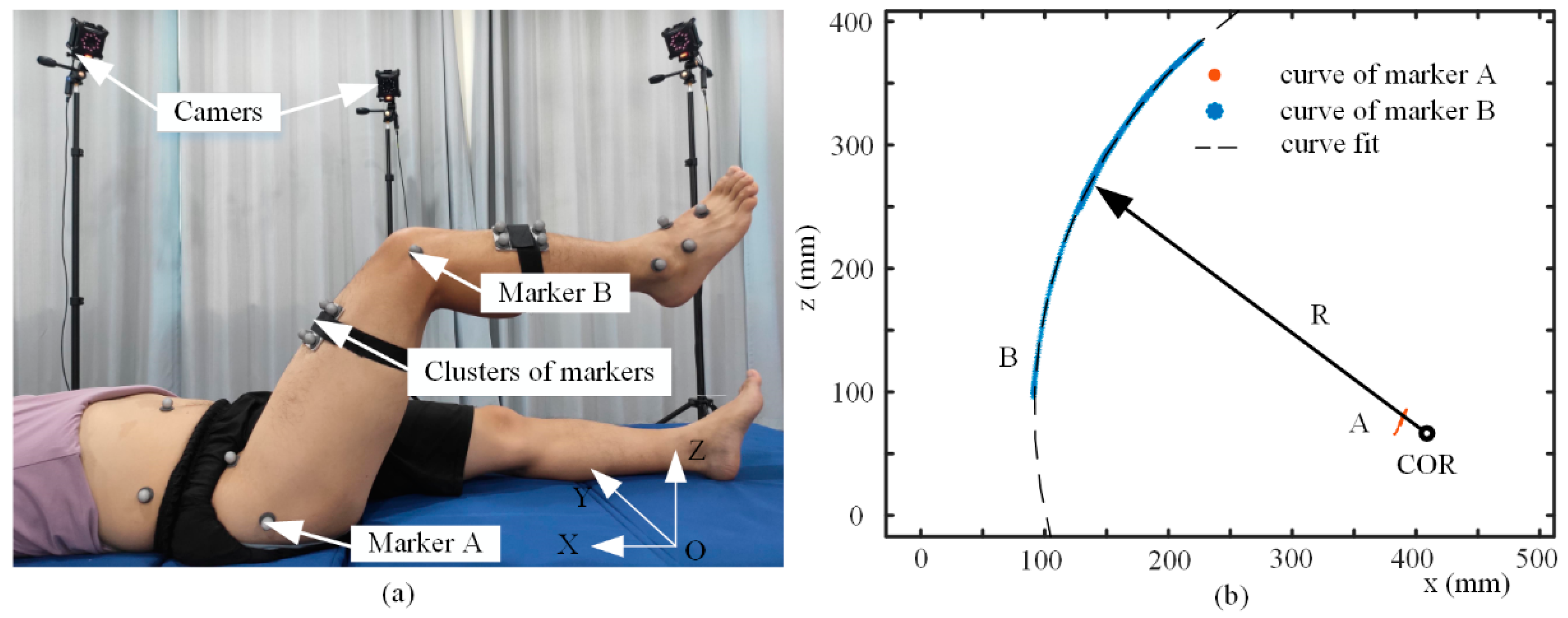
Figure 3.
An overview of the proposed robot. (a) Virtual prototype of the novel robot. (b) Exploded view of the underactuated mechanism.
Figure 3.
An overview of the proposed robot. (a) Virtual prototype of the novel robot. (b) Exploded view of the underactuated mechanism.
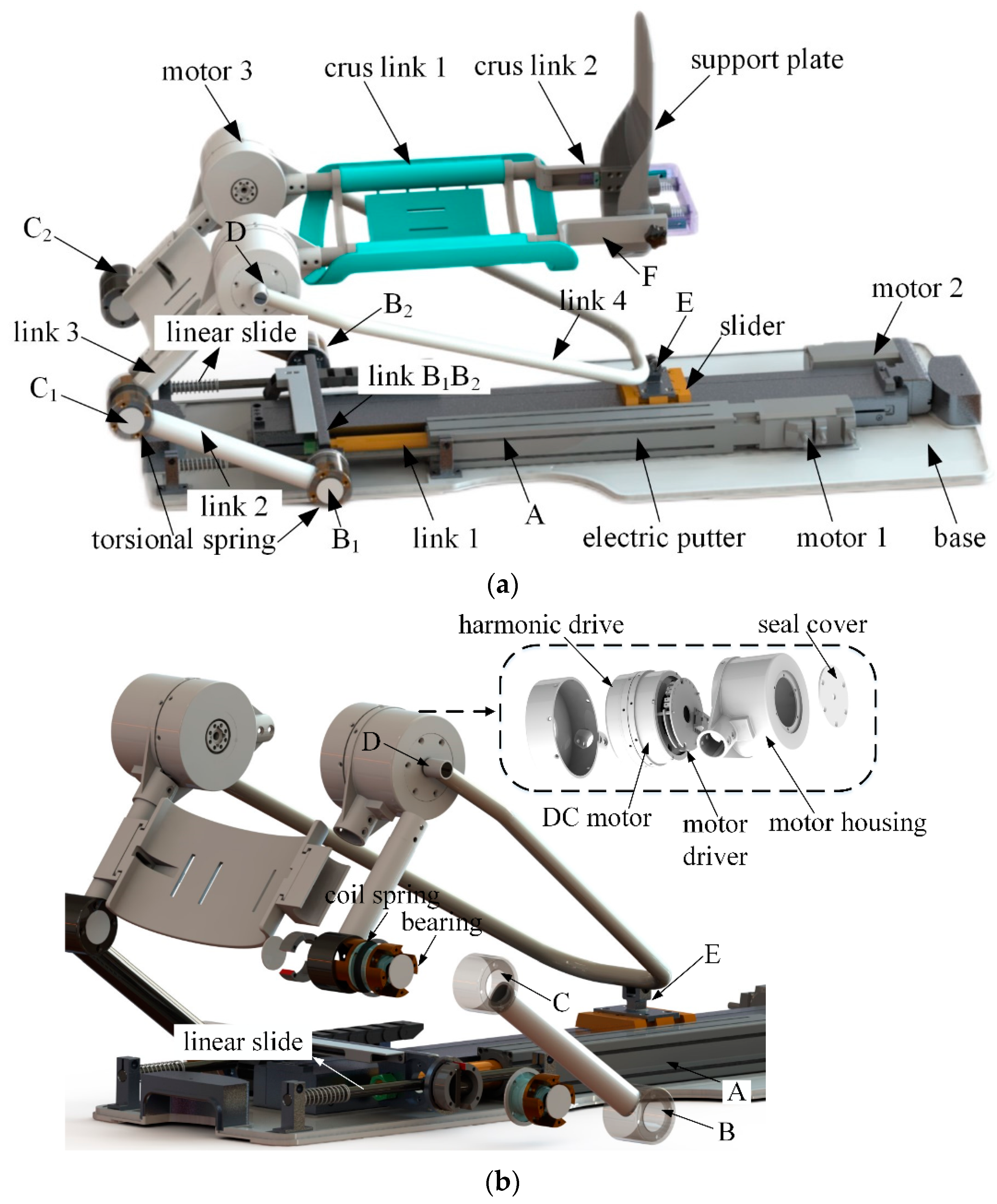
Figure 4.
(a) Schematic illustration of the structure. (b) Unloaded static model of the novel robot.
Figure 4.
(a) Schematic illustration of the structure. (b) Unloaded static model of the novel robot.
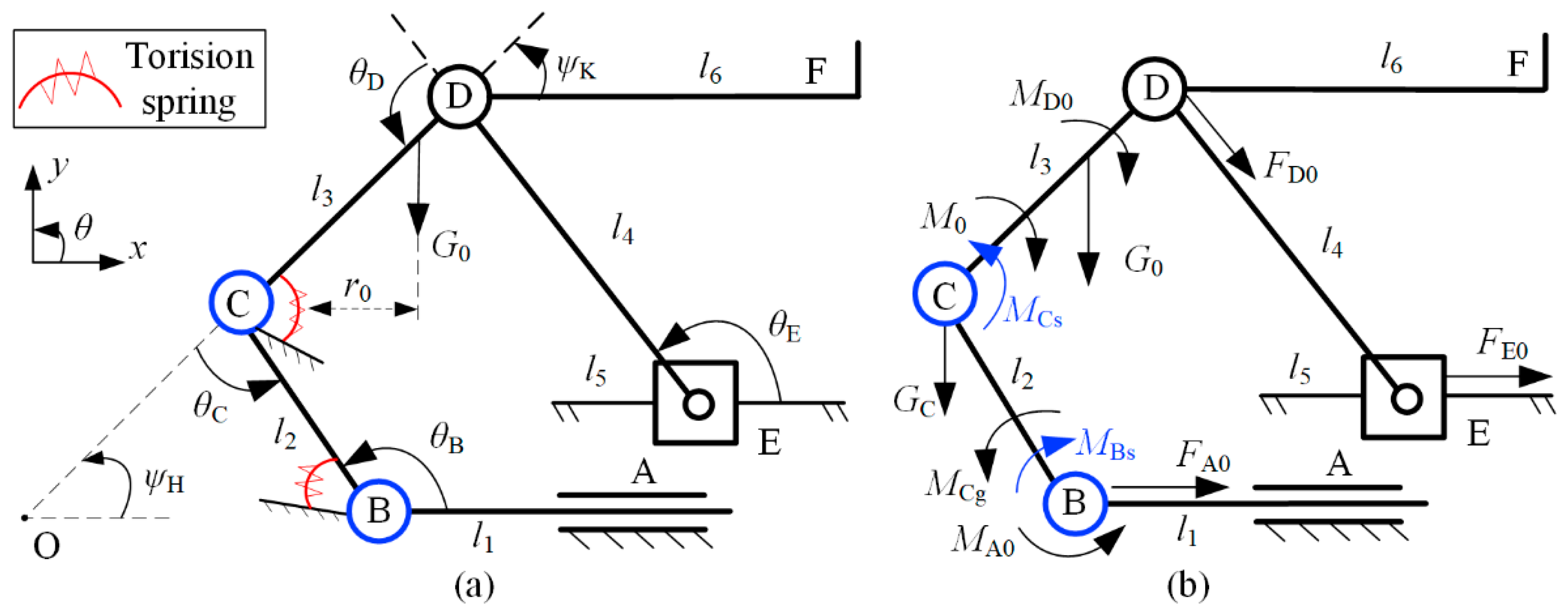
Figure 5.
Quasi-static model of the proposed robot in different movement directions. (a) Move to the left. (b) Move to the right.
Figure 5.
Quasi-static model of the proposed robot in different movement directions. (a) Move to the left. (b) Move to the right.

Figure 6.
Motion sequence of the underactuated five-bar linkage and equivalent virtual mechanism. (a) Joint E moves to the left and rotation of joint D. (b) Joint A moves to the left and rotation of joint C. (c) Equivalent mechanism EDO. (d) Equivalent mechanism BCO. Parameters r1 and r2 are the distance in the x direction from joints B and E, respectively, to point O. R1 and R2 are the trajectories of joints C and D.
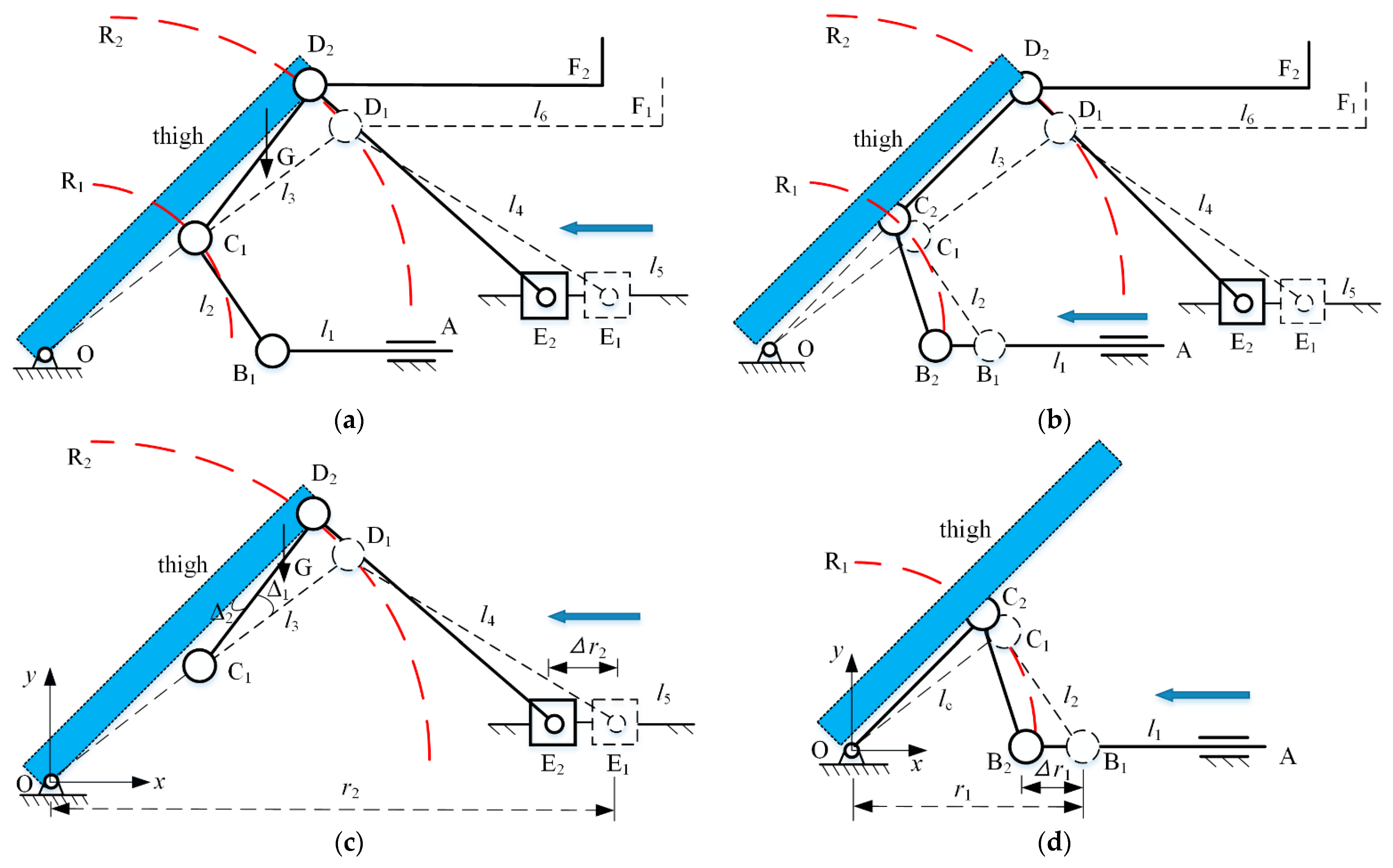
Figure 7.
Schematic plot of the two limit positions of underactuated five-bar mechanism. (a) The maximum hip joint angle, ΨH1 = 80°. (b) The minimum hip joint angle, ΨH2 = 20°. Parameters h1, h2, and h3 are the vertical distances between points O, B, and E and the base, respectively.
Figure 7.
Schematic plot of the two limit positions of underactuated five-bar mechanism. (a) The maximum hip joint angle, ΨH1 = 80°. (b) The minimum hip joint angle, ΨH2 = 20°. Parameters h1, h2, and h3 are the vertical distances between points O, B, and E and the base, respectively.
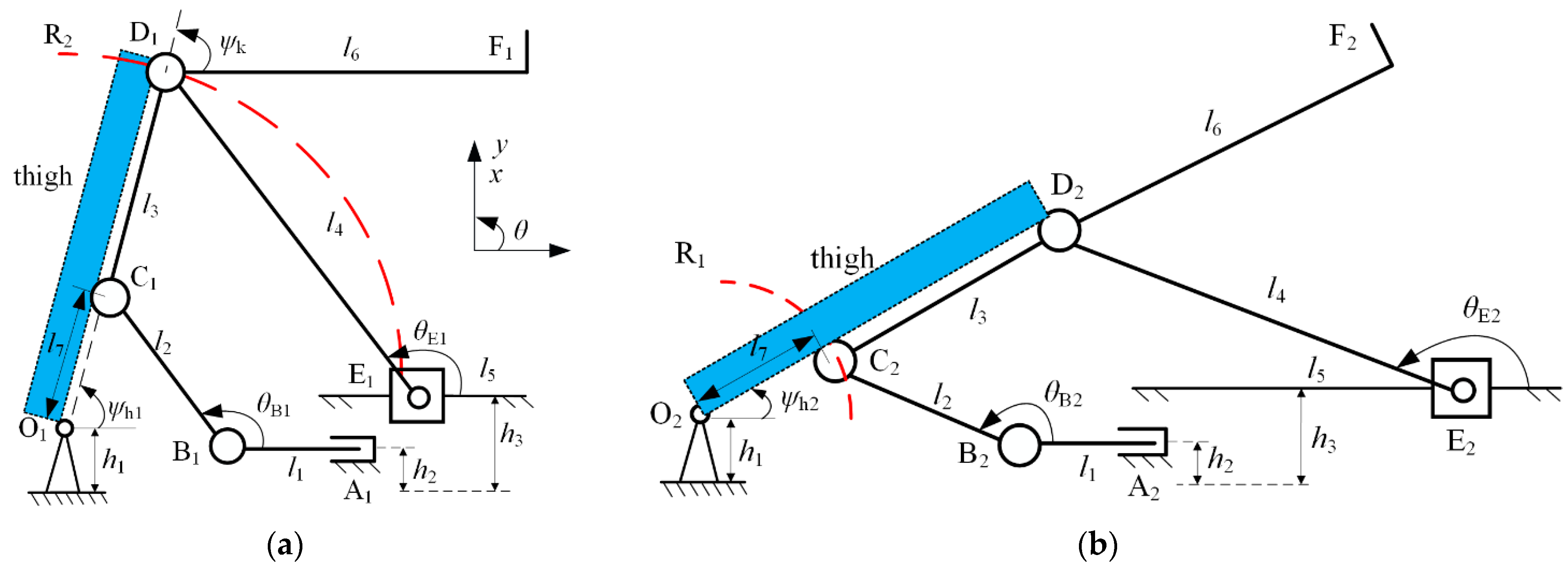
Figure 8.
Virtual prototype of the knee joint mechanism. α1 and θ1 denote the rotation angle of the crus bracket and ankle, respectively.
Figure 8.
Virtual prototype of the knee joint mechanism. α1 and θ1 denote the rotation angle of the crus bracket and ankle, respectively.

Figure 9.
Schematic structure of the robot and two three-bar slider-crank movements. (a) Parameters of the proposed robot. (b,c) Parameters of the equivalent slider-crank BCO and EDO, respectively. (d) Kinematic parametric model of the equivalent two-link mechanism.
Figure 9.
Schematic structure of the robot and two three-bar slider-crank movements. (a) Parameters of the proposed robot. (b,c) Parameters of the equivalent slider-crank BCO and EDO, respectively. (d) Kinematic parametric model of the equivalent two-link mechanism.
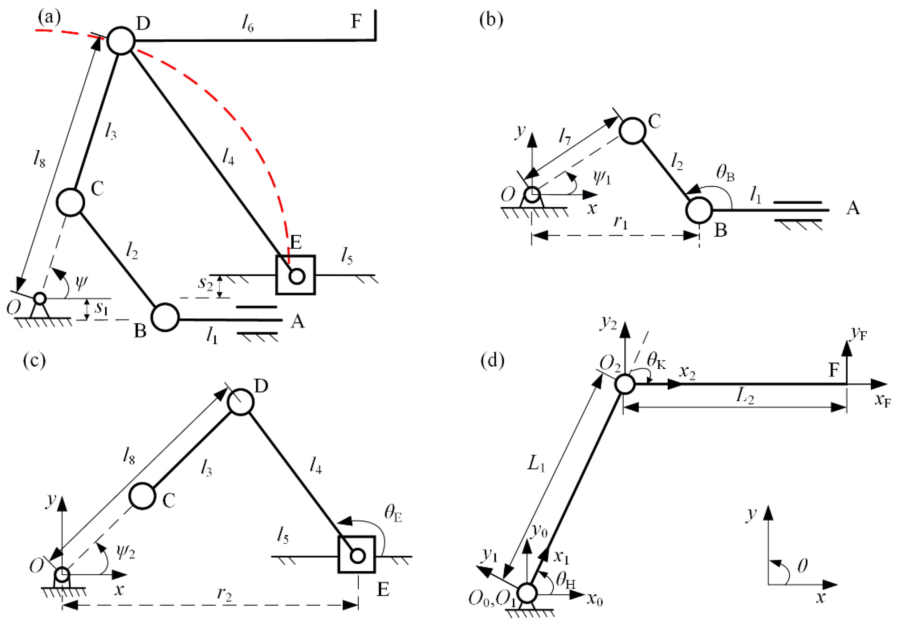
Figure 10.
Experimental setup during testing of the robot. (a) Performance tests for the arthro-kinematic compatibility, markers were placed on subjects and the robot. (b) Force-measuring sensors were placed on the shank.
Figure 10.
Experimental setup during testing of the robot. (a) Performance tests for the arthro-kinematic compatibility, markers were placed on subjects and the robot. (b) Force-measuring sensors were placed on the shank.
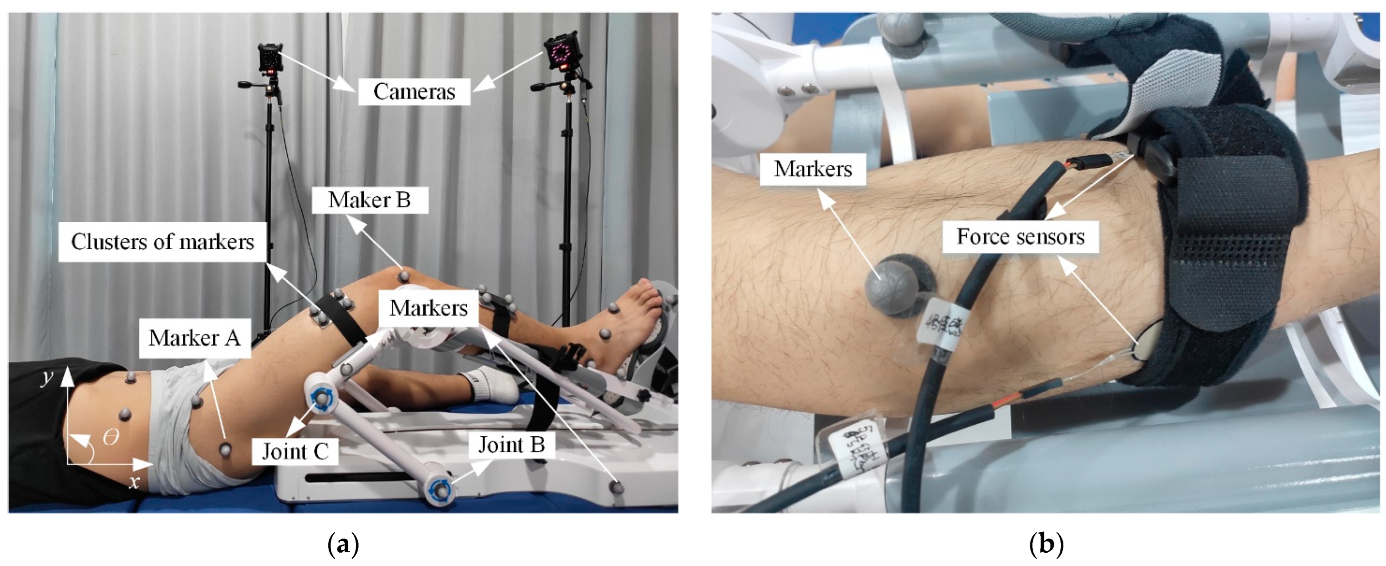
Figure 11.
Average results of the joint angles in different passive rehabilitation exercises. (a) Knee and hip joint angles in passive knee flexion–extension exercise. (b) Hip joint angles in passive elevation of the extended leg exercise. Shaded areas indicate ±1 SD.
Figure 11.
Average results of the joint angles in different passive rehabilitation exercises. (a) Knee and hip joint angles in passive knee flexion–extension exercise. (b) Hip joint angles in passive elevation of the extended leg exercise. Shaded areas indicate ±1 SD.
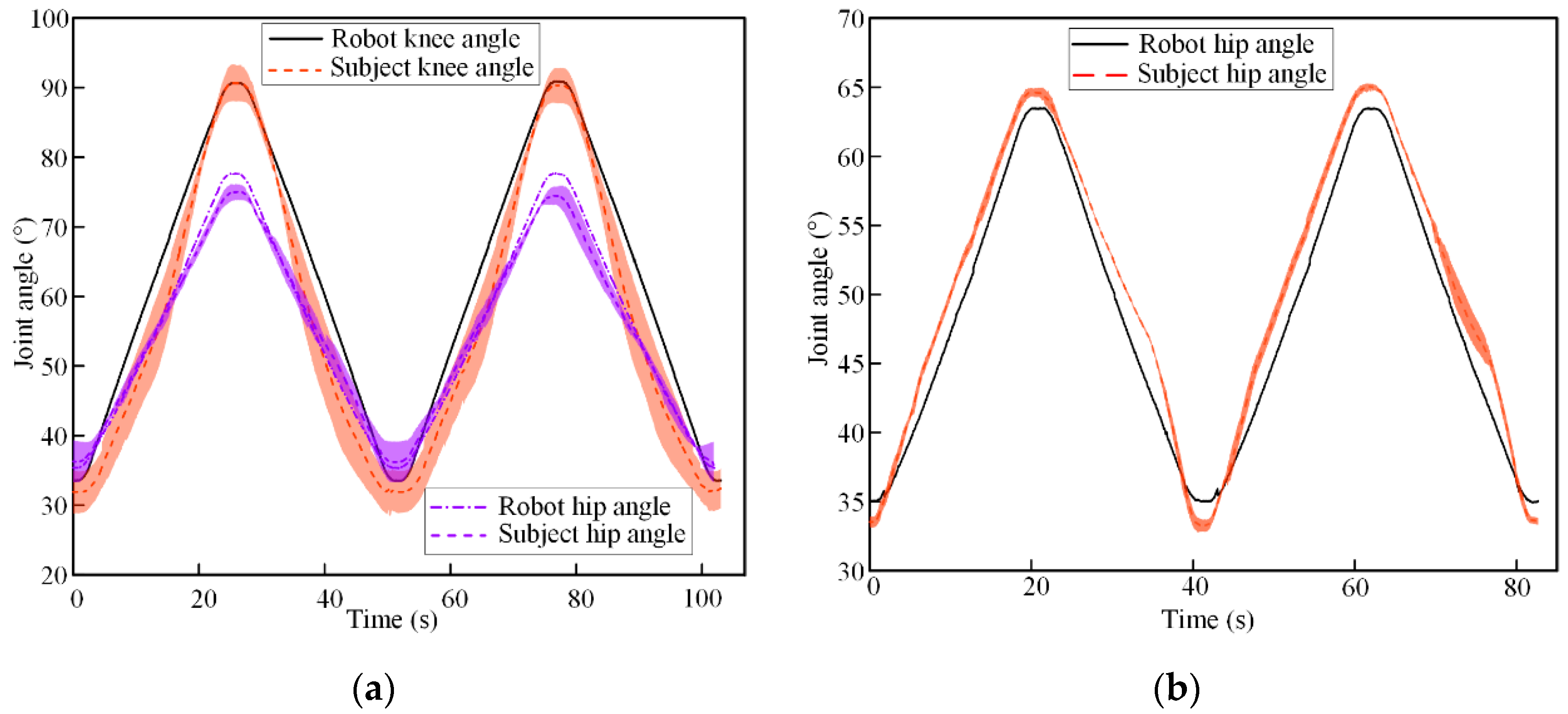
Figure 12.
(a) Mean values of the interaction forces at the shank, RMS value of interaction force is reported in the legend, shaded areas indicate ±1 SD. (b) Schematic diagram of the interaction forces between the human shank and the robot. Frobot is the force applied by the robot, and Fs is the interaction force measured by sensors.

Table 1.
The ROM of recommended rehabilitation exercises.
| Hip | Knee | Ankle | |
|---|---|---|---|
| Minimal angle (°) | 0 | 0 | −25 |
| Maximal angle (°) | 80 | 120 | 10 |
Table 2.
Mechanical structure comparison with other sitting/lying LLRR.
| Device | Size (L × W × H m3) | Weight (kg) | Complaint Type | Active DOF |
|---|---|---|---|---|
| Underactuated LLRR | 0.91 × 0.3 × 0.26 | 11.8 | Elastic strap and passive DOF | 3 |
| CLLRTR [34] | 2.3 × 1.2 × 0.8 | >50 | - | 3 |
| Lokomat [9] | 2.6 × 1.2 × 2.2 | >80 | Elastic strap | 4 |
| Hip Bot [29] | 2.0 × 1.0 × 0.7 | >50 | - | 5 |
| Motion Therapy [35] | 1.9 × 1.0 × 1.4 | 55 | Pneumatic muscles | 3 |
| iLeg [12] | 1.8 × 0.8 × 1.5 | >50 | Elastic strap | 3 |
Table 3.
The MD–H parameters of the equivalent two-link mechanism.
| i | αi−1 | ai−1 | di | θi |
|---|---|---|---|---|
| 1 | 0 | 0 | 0 | θH |
| 2 | 0 | L1 | 0 | θK |
| Point F | 0 | L2 | 0 | 0 |
Disclaimer/Publisher’s Note: The statements, opinions and data contained in all publications are solely those of the individual author(s) and contributor(s) and not of MDPI and/or the editor(s). MDPI and/or the editor(s) disclaim responsibility for any injury to people or property resulting from any ideas, methods, instructions or products referred to in the content. |
© 2023 by the authors. Licensee MDPI, Basel, Switzerland. This article is an open access article distributed under the terms and conditions of the Creative Commons Attribution (CC BY) license (https://creativecommons.org/licenses/by/4.0/).
Share and Cite
MDPI and ACS Style
Yang, Y.; Guo, J.; Yao, Y.; Yin, H. Development of a Compliant Lower-Limb Rehabilitation Robot Using Underactuated Mechanism. Electronics 2023, 12, 3436. https://doi.org/10.3390/electronics12163436
AMA Style
Yang Y, Guo J, Yao Y, Yin H. Development of a Compliant Lower-Limb Rehabilitation Robot Using Underactuated Mechanism. Electronics. 2023; 12(16):3436. https://doi.org/10.3390/electronics12163436
Chicago/Turabian StyleYang, Yunlong, Junlong Guo, Yufeng Yao, and Hesheng Yin. 2023. "Development of a Compliant Lower-Limb Rehabilitation Robot Using Underactuated Mechanism" Electronics 12, no. 16: 3436. https://doi.org/10.3390/electronics12163436
Note that from the first issue of 2016, this journal uses article numbers instead of page numbers. See further details here.