1. Introduction
Electromagnetically induced transparency is a quantum interference effect in a three-energy atomic system as a result of destructive interference between two laser beams [
1]. A transparent window of transmitted wave can be observed in the broad absorption spectrum [
2]. The strong dispersion around the transparent window leads directly to the slow-wave effect [
3]. Since the realization of electromagnetically induced transparency based on electromagnetic metamaterials by Zhang et al. in 2008 [
4], electromagnetically induced transparency metamaterials have been investigated further in the last decade. Therefore, the realization of electromagnetically induced transparency requires harsh experimental conditions because electromagnetically induced transparency is a quantum interference phenomenon in a triatomic system [
5]. These stringent experimental conditions, such as macroscopic instruments, stable gas lasers, and low temperatures [
6,
7,
8], have greatly hindered their use in practical applications. In recent years, the development of metamaterials has extended the study of the electromagnetically induced transparency effect. Electromagnetically induced transparency metamaterials avoid the harsh requirements of atomic systems and show excellent performance in visible light [
9], terahertz [
10], and microwaves [
11]. Electromagnetically induced transparency metamaterials have been used in biosensors [
12], switches [
13], and storage [
14], among others.
In general, electromagnetically induced transparency metamaterials consist of bright modes and dark modes. The dark mode is usually not excited by the incident wave, while the bright mode can be immediately and directly excited by the incident wave. Then, the dark mode is excited by the bright mode and a clearly transparent window appears in the transmission spectrum [
15]. It is important to note that the sharp phase change within the electromagnetically induced transparent window leads to the slowing down of wave propagation within a transparent window, leading to slow waves and a non-linearity effect. Therefore, the electromagnetically induced transparency phenomenon has been extensively employed for slow-wave equipment and can be applied to slow-wave devices, optical caching, modulators, sensors, communications equipment and optical signal processors [
16,
17,
18,
19]. Unfortunately, most of the electromagnetically induced transparency metamaterial schemes observed in metamaterials can only be implemented at stationary frequencies, and applications at different frequencies must directly vary the geometrical parameters of the device, which lacks active manipulation [
20].
The coupling to the incident field energy is the key to producing electromagnetically induced transparency phenomena. It can be one or more resonators coupled to the electric field of an incident wave or to the magnetic field of an incident wave. For example, Liu et al. and Vafapour designed an electromagnetically induced transparency metamaterial consisting of a cut line coupled to the electric field of the incident wave and two SSRs whose energy comes only from the near-field coupling of the cut line [
21,
22]. An electromagnetically induced transparency metamaterial is realized by two magnetically coupled resonances, one excited by the magnetic field of the incident wave and the other generated by near-field coupling [
23]. In the electromagnetically induced transparency metamaterials proposed by Zhu et al. and Liu et al. all the introduced resonators acquire the energy from the magnetic field of the incident wave [
24,
25,
26]. However, the majority of the proposed electromagnetically induced transparency metamaterials so far have been positioned on the planar perpendicular of these waves vectors and have been coupled to an electric field of the incident wave instead of the magnetic field. Based on the above research and analysis, our contribution proposed an electromagnetically induced transparency metamaterial parallel to a wave vector, which can be coupled simultaneously with the electrical fields and mechanical fields of the incoming waves.
2. Design Concepts and Simulation Results
First of all, we designed the metamaterial device as a three-dimensional structure. A substrate, a metal strip (MS) and a metal SRR are created in the x-z plane, and the SRR is rotated by 180° around the center to obtain the overall structure in this plane. Further, the whole structure in the x-z plane is rotated by 90° around the
z-axis and the two substrates are intersected to obtain our three-dimensional structure. In addition, this paper presents SSPs to realize tunable electromagnetically induced transparent metamaterials. According to the reported studies, SSP can be realized by GaAs or S-PINs [
27,
28], and the plasma frequency of SSP can be actively tuned by varying the bias voltage to change the operating state of the SSP cell. Thus, by setting two different plasma frequencies, we can obtain the metallic and dielectric states of the SSP, called excited and unexcited states, respectively. Our simulation experiments were conducted in CST STUDIO SUITE, which is a comprehensive 3D electromagnetic field simulation software. We used the microwave RF module of the CST STUDIO SUITE simulation software, clicked on periodic structures as well as structural units and setup the frequency domain solution. The frequency domain finite element method is used by default and the tetrahedral mesh accuracy is setup to solve Maxwell’s system of equations. In addition, we have set the appropriate operating frequency and the boundary conditions set by default. At the same time, in order to obtain a clearer understanding of the direction of the current and the distribution of the electric and magnetic fields, we also need to setup a number of field monitors at different frequencies. In the Navigation Tree, 2D/3D Results, we can observe the current direction and electric and magnetic field distribution at the desired frequency points. In this simulation, we set the appropriate working frequency to 0.4 THz–0.9 THz, and set the field monitor frequency to 0.501 THz, 0.541 THz, 0.599 THz, 0.71 THz, 0.741 THz, 0.8135 THz. Such an operation setup makes it very convenient to observe the current direction as well as the electric and magnetic field distributions, which helps us to interpret the simulation results logically and accurately and to verify the correctness of the simulation results. In our simulations, in order to simulate the tunable material SSP in the software CST, a Drude model was created to describe its dielectric constant
as shown in the following Equation [
29]:
where
stands for plasma frequency and
stands for collision frequency. In our simulation, we set
= 12.8,
= 1.65 ×
rad/s,
= 2.9 ×
rad/s for the metallic state, and
= 2.9 ×
rad/s for the dielectric state.
The thickness of this substrate is set to
d1 = 8 μm, length
a = 260 μm and width
b = 210 μm. it is a hybrid material and its loss tangent and dielectric constant are set to 4.5 and 0, respectively. As shown in
Figure 1, is the fundamental unit of our designed reconfigurable three-dimensional electromagnetically induced transparency metamaterial with low loss and large group delay. The thickness of the metal resonator is set to
d2 = 0.35 μm. the length of the MS resonator is
p = 165 μm and
w3 = 12 μm. the radius of the metal SRR is set to
r = 26 μm, the width
w4 = 12 μm and the opening width
w1 = 13 μm. We use electromagnetic simulation software based on the finite element method to simulate the structure numerically and optimize the parameters. The boundary conditions are set as periodic boundary conditions in the x-y direction and open boundary conditions in the z direction during the simulation. After parametric optimization, the optimized parameters of the structure have been obtained. The remaining structural parameters are also given by us:
w2 = 12 μm,
n2 = 54 μm, and
n1 = 85 μm.
3. Discussion and Analysis of Results
In order to reduce the loss of the electromagnetically induced transparency metamaterial, the radiation loss of a SRR is supposed to be significantly curtailed. We shall validate the significant improvement in the loss performance from a SRR by arranging the rotated SRR for an existent SRR metamaterial. The new rotated SRR provides the existing SRR with residual current in the opposite direction. However, the two distorted SRRs have surplus currents that cancel one another out. As a result, the radiative loss in the whole metamaterial is significantly suppressed, so that the low-loss magnetized metamaterials have been realized.
As mentioned above, the losses at the terahertz bands resulting from SRR surplus currents are generally large. To suppress the radiation loss, the SRR was turned by 180° around the central to generate contrary surplus currents, which canceled one another out, as evidenced by the above current distribution diagram as well. To obtain a clearer understanding of the physical mechanisms for this proposed metamaterial loss reduction,
Figure 2 shows the surface current distribution of the SRRs. It is shown that for SRRs, the currents in the two SRRs are flowing in opposite directions. And the overall magnetic field is enhanced by the summation from the magnetic field produced in every SRRs. Therefore, the total summation from a magnetic field produced in every SRR enhances the overall magnetic field, resulting in a significant increment in the negative permittivity effects. Meanwhile, it is as well noted that a remnant current is mostly distributed in the arms of the SRRs, as well as the current directions in the arms of these two SRRs are opposite and the current strengths are comparable, this implies the remnant currents in the two SRRs cancel each other out. The mutual cancellation results in the radiative loss from metamaterials being significantly inhibited. Thus, this low-loss electromagnetically induced transparency metamaterial is obtained by us. The proposed loss reduction mechanism was by no means restricted to such a structural array. With all metamaterial structures, low-loss metamaterials may have been achieved through suppression of the remnant current.
The resonant oscillator model with coupled bright modes and dark modes of electromagnetically induced transparency metamaterials can analog electromagnetically induced transparency and produce electromagnetically induced transparency phenomena. The bright mode as well as dark mode corresponding with the inspired states and sub-stable states of an atmospheric regime, respectively. Moreover, the previous one may be coupled to an away field and receive energy from the incoming field with a smaller quantity factor (Q), in contrast with the later one [
30], and its energy can only be obtained by coupling to the bright mode.
For simultaneous excitement with electrical as well as magnetic resonances to generate an electromagnetically induced transparency window, the surface induced current of a quasi-dark mode comes not only from close-field coupling with the bright mode, but also from the excitement of the magnetic fields of an incident wave. In contrast to the electrical resonance close-field coupling into magnetic resonances as well as magnetic resonance close-field coupling into magnetic resonances, a quasi-dark mode surface-induced current is not only derived from the bright mode closed-field couplings but also from the excitement of an incoming magnetic field. A strongly inducted surface current in that quasi-dark mode results in lower radiative losses as well as higher transmission levels because of the suppression of the magnetics dipole. The difference between the bright mode and quasi-dark mode Q values for the simultaneous excitation of electrical and magnetic resonance is larger compared to the simultaneous excitation of electrical resonance. The significant difference in Q values is also one of the design rules for electromagnetically induced transparency. Therefore, the simultaneous excitement of electrical as well as magnetic resonances could compensate for a lack in the available design. In our work, the coupling impact of the simultaneous excitation of electrical and magnetic resonances is investigated. These MS resonators and SRR resonators with different Q values are used in bright modes and quasi-dark modes, respectively.
This mechanism is further explained by analyzing mode 1. As shown in
Figure 3, the resonant excitation frequencies of the two MSs and four SRRs are 0.616 THz with a transmission rate of 3.327% and 0.506 THz with a transmission rate of 5.602%, respectively. Their full-width half-maximum (FWHM) bandwidths are 0.07328 THz and 0.01992 THz, respectively. On closer calculation, Q is derived using the following equation:
where
stands for resonance frequency,
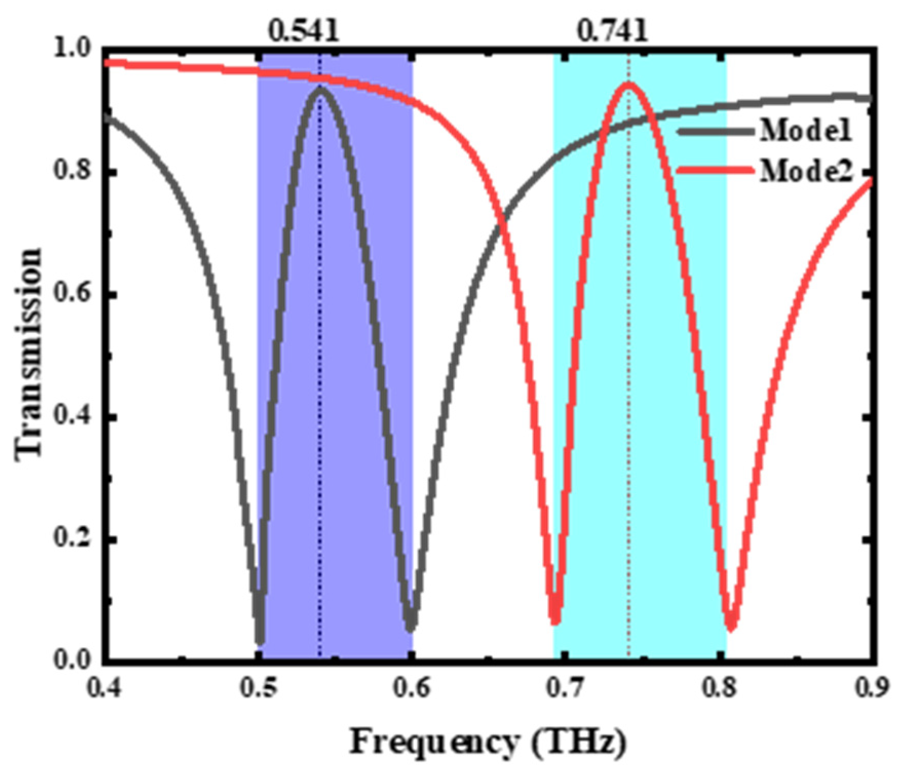
stands for FWHM bandwidths, and the numerical expression for two MSs (5.169) is less than four SSRs (25.391). As a result, the two MSs with smaller Q values are bright modes, while the four SRRs with larger Q values are quasi-dark modes. Also, the largest discrepancy in the Q value between these two makes it possible to generate the electromagnetically induced transparency. In the interaction of these two modes, there is a transmission peak of 92.05% at 0.541 THz, the lower frequency resonance declining with a transmittance of 3.33% at 0.501 THz, and the higher frequency resonance declining with a transmittance of 5.44% at 0.599 THz, producing an electromagnetically induced transparency window with FWHM bandwidths of 0.0668 THz.
The mechanisms for this are more explicitly illustrated by an electric field distribution, as shown in
Figure 4; two SRRs and MS show a stronger electric field at 0.501 THz and 0.599 THz, respectively, which indicates that they could be coupled to and gain energy from the incident field alone. At 0.541 THz, the electric field with two SRRs is greater than that of the MS, indicating the fact that as well as gaining energy from an incident electric field, it also gains energy from MS coupling. In the meantime, the integral current at 0.541 THz is much weaker than that at 0.501 THz and 0.599 THz. This indicates the presence of damaging interferences across the two SRRs and the MS as well as the poor absorption of incident electrons by the metamaterials. A few incident electromagnetic waves are absorbed by the metamaterial, and a transmission peak is created. In addition, two SRRs of large Q values are less prone to dissipating power and promote electromagnetically induced transparency generation. The two SRRs and MS currents are opposite, indicating that their individual produced field counteract one another to produce a de-structured disturbance. This is in agreement with the characterization for bright and pseudo-dark modes as well as in the procedure for the formation of the phenomenon of electromagnetically induced transparency.
What is most fundamental about the phenomenon of electromagnetically induced transparency is that it is accompanied by a strong dispersion of chromatic colors in the vicinity of the window of transparency. This strong dispersion phenomenon is an important reason for the formation of the slow-light effect. Therefore, the slow-light effect is the most representative electromagnetic feature of the electromagnetic induction transparency phenomenon, and it is also the earliest electromagnetic feature that has attracted the attention of researchers. Electromagnetically induced transparent metamaterials with good slow-light effect are extensively used in slow-light equipment. The group delay is the principle to judge the strength of slow light in electromagnetically induced transparent metamaterials. In recent years, researchers have been trying to improve the group delay of electromagnetically induced transparent metamaterials as much as possible through structural designs, so as to realize stronger slow-light efficiency. Slow-wave propagation is another characteristic of electromagnetically induced transparency metamaterials. In order to demonstrate this property in our designed metamaterials, the maximum group delay that the designed metamaterials can provide was calculated. The generation of electromagnetically induced transparency is often accompanied by significant slow-wave effects and large group delays. The slow-wave effect is a phenomenon in which the group velocity of light in vacuum is less than the speed of wave due to dispersion. In the electromagnetically induced transparency window, the phase change is significant, bringing about a significant slow-wave effect and a significant group delay. The group delay of electromagnetically induced transparency is specifically calculated as follows [
31]:
where
φ is the transmitted phase shift,
ω = 2
πf,
f is the frequency, and
t is the thickness of the metamaterial.
Figure 5 represents the group delay in mode 1 and mode 2. In the electromagnetically induced transparency window in mode 1, the group delay peaks at 261.51
at 0.505 THz. Similarly, in the electromagnetically induced transparency window in mode 2, the group time delay peaks at 785.09
at 0.723 THz. According to Equation (4) and
, group velocity passing this electromagnetically induced transparency metamaterial in mode 1 or mode 2 is 1096.1- or 420.1-fold slower than the group velocity in air passage, achieving ultra slow waves. This enables effective application in slow-wave devices, optical caching, modulators, sensors, communications equipment and optical signal processors.
Moreover, the maximal delay bandwidth product (DBP) represents the effectiveness in message storing and transmitting, as well as the quality of the slow-wave phenomenon, given by [
32]:
where
is the FWHM bandwidth (0.0668, 0.0802) and
represents the group delay spike. In mode 1 and mode 2, the maximal DBP is 17.51 and 62.96, respectively, which marks the high efficiency of the communication device.
Table 1 lists the comparison of FHWM, group delay, DBP and polarization independence in this work and previous reports. It can be seen that our work is excellent in terms of group delay and DBP, which indicates that our metamaterial has some applications in broadband filters and slow optical devices. (The reference with * is experimental work, whereas the others are simulations.)
The inspired and uninspired states influence the resonant responses and the electromagnetically induced transparency window by means of the modulation mentioned in
Section 2. As shown in
Figure 6, the transmission peak frequency in mode 2 is 0.741 THz, and a frequency shift of 0.2 THz is achieved by comparison with mode 1. The mechanism of generating the electromagnetically induced transparency window in mode 2 is the same as that of mode 1. The two MSs with smaller Q values are bright modes, while the four SRRs with larger Q values are quasi-dark modes. Also, the largest discrepancy in the Q value between these two makes it possible to generate the electromagnetically induced transparency. In the interaction of these two modes, there is a transmission peak of 93.01% at 0.741 THz, the lower frequency resonance declining with a transmittance of 1.61% at 0.711 THz, and the higher frequency resonance declining with a transmittance of 7.98% at 0.809 THz, producing an electromagnetically induced transparency window with FWHM bandwidths of 0.075 THz. At 0.741 THz, the electric field with two SRRs is greater than that of the MS, indicating the fact that as well as gaining energy from an incident electric field, it also gains energy from MS coupling. In the meantime, the integral current at 0.741 THz is much weaker than that at 0.711 THz and 0.809 THz. This indicates the presence of damaging interferences across the two SRRs and the MS as well as the poor absorption of incident electrons by the metamaterials. A few incident electromagnetic waves are absorbed by the metamaterial, and a transmission peak is created.
The transmission spectrum in mode 2 is shown in
Figure 6. Again, there is a 93.01% transmission peak at 0.741 THz, 1.61% at 0.711 THz, and 7.98% at 0.809 THz. The electromagnetically induced transparency window has FWHM bandwidths of 0.075 THz. The surface current analysis for mode 2 is similar to that of mode 1. What is different is that the total current is slightly higher at the peak electromagnetically induced transparency frequency, resulting in a slightly higher transmission peak.
As shown in
Figure 7, the transmission spectra under TM waves, TE waves, LCP waves, and RCP waves are identical, indicating the polarization insensitivity of the presented metamaterial. Next, the transmission spectra of the presented metamaterials at TE polarization waves while under different incidence angle conditions are shown in
Figure 8. It can be seen that both mode 1 and mode 2 exhibit excellent polarization-insensitive properties.
4. Conclusions
In conclusion, in this paper, a different type of metamaterial structure that can be excited by both electrical and magnetic resonance is presented. This electromagnetically induced transparent metamaterial has excellent slow-wave effects, low loss, reconfigurable properties, and polarization-insensitive properties. The SSP can operate in two different modes—with or without excitation. Mode 1 has a peak transmission of 92.05% at 0.541 THz while mode 2 has a peak transmission of 93.01% at 0.741 THz, resulting in a bandwidth shift of 0.2 THz. The maximum group delay of 261.51 ps and 785.09 ps as well as the delay bandwidth product of 17.51 and 62.96 at mode 1 and mode 2, respectively, indicate a good slow-wave effect with a high efficiency of communication devices. In addition, the metamaterial structure possesses low-loss properties and polarization-insensitive properties. Currently, most of the electromagnetically induced transparent metamaterials have been designed and studied based on two-dimensional planes. There are relatively few studies on three-dimensional electromagnetically induced transparent metamaterials. However, the majority of the proposed electromagnetically induced transparency metamaterials so far have been positioned on the planar perpendicular of these waves vectors and have been coupled to an electric field of the incident wave instead of the magnetic field. Based on the above research and analysis, our contribution proposed an electromagnetically induced transparency metamaterial parallel to a wave vector, which can be coupled simultaneously with the electrical fields and mechanical fields of the incoming waves. Our proposed metamaterial structure, due to its unique characteristics, can be widely used not only for slow-light devices, communications, sensors, etc., but also provides some new design ideas.


