Article

Mathematical Channel Modeling of Electromagnetic Waves in Biological Tissues for Wireless Body Communication

1
Innov’COM Laboratory, Sup’Com, University of Carthage, Technological City of Communications, Route de Raoued Km 3,5, Ariana 2083, Tunisia
2
Innovative Technologies Laboratories (ITL), Computer, Electrical and Mathematical Sciences & Engineering (CEMSE), King Abdullah University of Science and Technology (KAUST), Thuwal 23955, Saudi Arabia
*
Author to whom correspondence should be addressed.
Electronics 2023, 12(6), 1282; https://doi.org/10.3390/electronics12061282
Submission received: 9 February 2023 / Revised: 3 March 2023 / Accepted: 4 March 2023 / Published: 7 March 2023

Abstract

:
In the wireless body area network (WBAN), radio propagations from devices that communicate with the human body are very complex and distinctive compared to other environments. As we know, the human body is a lossy channel that significantly attenuates the propagation of electromagnetic waves (EMW). Therefore, channel models are critical in evaluating the communication link. One of the most predominant models is the path loss channel model, which is used to cover a wide range of communication channels and frequency bands in WBAN. This paper investigates the EMW in a human model irradiated by an incident electromagnetic plane wave. A planar multilayer structure is used for modeling human tissue. Moreover, the steady-state electromagnetic distribution is calculated by solving the differential and integral equations (DIE) by using the method of moments (MoM). The obtained results demonstrate the great use of performing a theoretical analysis for path loss (PL) and power loss density (PLD) estimation. The magnitude of the electric field inside muscle tissue at various depths, and with the most important frequencies in medical applications, is evaluated. This investigation provides evidence that the penetration of EMW in biological tissue strongly depends on the frequency and thickness of the tissue involved. Thus, for different examined conditions, an excellent agreement between recent results that were obtained by an analytical method, finite element (FEM), and the proposed MoM method is verified to be valid in this investigation, and it is found that the distribution of the field, PL, and PLD for different communication scenarios is very promising to determine the quality of communication for WBAN technology.

1. Introduction

Wireless body area network (WBAN) is a wireless communication designed to operate in close proximity to the human body. They are often used for health monitoring, location tracking, and emergency services, as they allow devices to communicate wirelessly without the need for physical connections [1]. One of the key issues in the development of WBANs is the requirement for antennas [2]. That must strictly comply with the regulatory requirements for the specific absorption rate (SAR). These requirements are essential for these devices to operate safely near the human body for long periods of time [2,3]. To address the issue of WBAN, researchers developed compact and flexible antennas, which can conform to the shape of the body and minimize the losses phenomena [4]. Moreover, there are still challenges to be addressed in the development of WBAN, including power consumption, data rate, and interference with other wireless systems.
There are three communication scenarios for a WBAN channel model: in-body, on-body, and off-body. On-body communication involves sensors on the surface of the body that are connected to a link node, while in-body communication involves linking body implants within the body. Off-body communication involves sensors and coordinators that communicate within 3 m around the human body [5]. The signal propagation in these different communication scenarios varies due to the differing propagation medium [6].
Furthermore, modeling the behavior of WBAN can be challenging due to the complex distinctive of human tissue. When the signal propagates as electromagnetic waves on or near the human body, it can be affected by attenuation and interference, which can degrade the quality of the signal [7]. This is because human tissues behave similar to a high-brightness dielectric, which can alter the radiation pattern, polarization, and coincidence of the signal [7,8].
An accurate channel model for WBAN must choose suitable propagation paths. Among the works, different channel models for WBAN are proposed in [9,10,11]. To overcome excessive power losses due to prospective channel human losses, a path loss model with rigorous estimation must be taken into account to analyze the radio link loss in implant communication. This being the case, the modelling of the physical layer is an essential first step. Industrial, scientific, and medical (ISM, 2.4 GHz) and ultra-wideband (UWB, 3.1–10.6 GHz) technologies are increasing in popularity because of their ability to transmit data at high data rates while consuming a low amount of power, which could improve the standard for wireless communications [12,13]. Analytically solving the equations of heterogeneous human tissues with different geometrical complexity is a very hard problem, which the analytic study provides a more detailed understanding of the propagation mechanisms than the simulation study, especially at the interfaces of the layers. For this reason, several approaches have been reported in the literature to solve the electromagnetic characteristics of a lossy medium numerically in either differential or integral form by solving Maxwell’s equations [14,15]. These techniques are divided into two groups: frequency domain and time domain. The most successful method in the time domain is the FDTD [16,17]. It is an effective tool for modelling a miniature structure for analyzing near-field microscopy for electromagnetic compatibility applications [18]. However, FDTD requires a large computation time and memory, as it uses a uniform mesh to model the entire computational domain, which does not conform to curved surfaces (as a spherical or cylindrical boundary). The frequency domain approaches include the method of moments (MoM) [19]. Compared to MoM, FDTD requires the entire domain analysis to be meshed into small cells, with a size smaller than the smallest wavelength used in the simulation. It also assumes the use of homogenous mesh cells, which can become impractical in complex models involving several different materials. Moreover, MOM operates in the frequency domain, and can accurately be used to analyze the complex behavior of heterogeneous material properties. It is a very powerful method when studying inhomogeneous complex shapes [20,21,22].
The main challenges of WBAN involve the implant’s communication channel, as it solely comprises living tissues with layers exhibiting different electromagnetic properties that should be estimated and incorporated into the channel model. This challenge makes the simulation of the channel, multi frequency modeling, and model’s validation complex. This article presents a comprehensive investigation of the WBAN channel model for the wireless communication pattern, including factors such as PL, PLD or skin texture, as these factors determine the quality of the signal communication. In addition, a mathematical formulation is based on the solution of DIE using the MoM is developed. The choice of MoM is that we can present, in the frequency domain, an efficient electromagnetic solution to deal with large structures with short computation times and sufficient computing resources. The proposed investigation has been validated through FEM computations and comparison with an analytical result [12]. The good agreement of the results confirms the validity of the proposed approach and paves the way for the development of a WBAN communication system.
The rest of the paper is set as follows: Section 2 presents the proposed model, where we discuss the parameters and characteristics of human tissue. Section 3 describes the two proposed mathematical formulations. The results and comparison are explained in Section 4. In Section 5, the paper is finally summarized and concluded.

2. Proposed Model

2.1. Characteristics of Human Tissue

According to previous studies, the electrical properties of human tissues change with frequency. There is a database available for tissue parameters [23]. Table 1 includes information for several tissues and different frequencies. The penetration depth, as defined by the Equation (1), is the distance over which the field decreases to (1/e) of its value just inside the layer boundary. Due to reflection, the field E i inside the boundary may already be much smaller than the incident external field. The penetration depth [23] can be determined by applying Equation (1):
δ = 1 ω μ ε 2 1 + σ ω ε 2 1 1 2 ,
where δ is the penetration depth (Pd), ω is the 2πf and f is the frequency, µ is the electromagnetic permeability, ε is the electromagnetic permittivity, and σ is the electric conductivity.
Figure 1 depicts the penetration depth of human tissue as a function of frequency. To penetrate the tissue, the Pd must be greater than the tissue thickness.
According to [24], we can state the decrease in the field strength by Equation (2):
E z = E i e z δ ,  
where E z is the field at the distance z and E i is the field just inside the boundary. As mentioned in Equation (3), the E-field inside the human tissue combines the wave that arrived and the reflected from the next tissue.
E z = E i e z δ τ e z δ ,  
τ represents the reflection coefficient of the next tissue, because there are multiple reflections within each tissue that attenuate the wave. Therefore, the question is more complicated.
In the next subsection, two configurations that were analyzed through calculations and simulations are discussed.

2.2. Lossy to Lossy Medium: Fat to Muscle Human Tissue

First, a simple layer approach is considered here, transmitting antenna Tx placed in a lossy medium, on the muscle tissue medium, which has a thickness of 20 mm. This configuration is illustrated in the accompanying Figure 2. We assume the Tx is in a fat layer on the surface of the muscle. The receiving antenna Rx is placed in the lossy medium of human muscle tissue. For this study, various Rx locations are investigated. In order to model the PL using plane wave, the Tx is placed on the surface of the muscle layer to ensure that a plane wave is obtained when the waves reach the muscle tissue layer.

2.3. Lossless to Lossy Medium: Air to Layers Equivalent to Human Tissue

This configuration involves creating a structure for human tissue that is similar to the one described in the reference [12], as shown in Figure 3. The Tx antenna is placed on the skin, and the insulated Rx antenna is placed in the layered model. This layered model consists of the skin (1.5 mm), fat tissue (8.5 mm), and ends at the muscle layer (27.5 mm). In this scenario, to better understand the behaviors of deep propagation, two different communication scenarios, OB2IB and IB2OB, are studied.

3. Mathematical Formulation

3.1. Selection Method

The electromagnetic problem should be analyzed with the configuration behavior, and, based on the modelling methods, they can be applied to solve the problem.
  • MoM is most useful for unbounded problems related to radiation elements. It is efficient in terms of performance, precision, and execution time;
  • FEM is based on the large-volume configuration for analysis. It is useful for large problems with complex, inhomogeneous configurations. Nevertheless, it does not support unbounded conditions;
  • FDTD is a time-domain technique and is the most efficient for transient analysis problems. It is effective for complex, unbounded, and inhomogeneous problems. The disadvantage of FDTD is the complexity of the analysis, which requires more execution time.
In this study, we need a method that can be implemented for efficient communication inside the human body. MoM is the quintessential requirement for exploration. The formulation has been validated by using the plane wave propagation formula and the concept of transmission line analogy. MoM is one of the most well-known approaches to electromagnetic problems [20]. This technique is based on reducing the operator equations to a system of linear equations that can be written in matrix form. One of the advantages of employing this approach is that the result is extremely precise, since the equations are almost exact and MoM offers a direct numerical solution to these equations. The incident wave may collide with the tissue, forming certain angles (other than 90°) with it. This is an instance of oblique incidence. There are two main varieties of oblique incidence, depending on whether the electric field is normal to it (perpendicular polarization) or is parallel to the plane of incidence (parallel polarization). In the next section, both kinds are explained.

3.2. MoM Formulation

3.2.1. TE Case

In perpendicular polarization, the y-component is the electric field E y that is normal to the plane of incidence. We obtain from Faraday’s law and Ampere’s law the differential equations that describe the problem.
d E y d z = j ω μ z H x ,  
d H x d z = σ z + j ω ε z + k x 2 j ω μ z E y ,  
H z = k x μ z E y .
where k x 2 c sin θ i , and c is the velocity.

3.2.2. TM Case

In this case, the plane of incidence can be determined by the axes of the interface, and normal to the interface, which is the xz-plane.
d H y d z = σ z + j ω ε z E x ,  
d H x d z = j ω μ z + k x 2 σ z + j ω ε z H y ,  
E z = j k x σ z + j ω ε z H y .
Furthermore, there are boundary conditions that enforce the continuity of tangential EM fields at the boundaries (at z = 0 and z = d). According to Figure 2 and Figure 3, we can write:
E t 0 + η H t 0 = 2 E i ,
E t d + η H t d = 0 ,
where
E i 2 E 0 , 2 E 0 cos θ i ,    
η s μ 0 ε 0 1 cos θ i ,               T E μ 0 ε 0 cos θ i ,         T M
and
η L j ω μ 0 σ + j ω ε 1 cos θ i ,             T E j ω μ 0 σ + j ω ε cos θ i ,         T M    
Differential equations (DE) do not have an analytical solution in most cases. Therefore, DE must be solved numerically [14,15]. Alternatively, the differential equations can also be converted into integral equations. The efficiency with which the resulting integral equation may be solved makes this technique an interesting way to investigate the effects of the incident wave inside the tissue. To convert Equation (4) to Equation (9), into integral equations, as an example, we integrate Equation (4)
d E y d z = j ω 0 z μ z H x d z + C .  
where C is a constant, which can be determined according to the boundary conditions Equation (11). Thus, the integral equations obtained may be stated in the following general form:
E t z = η l η l + η s E i + η s η l + η s 0 d Z ( z ) H t z d z η l Y z E t z d z 0 z Z ( z ) H t z d z ,
H t z = E i η l + η s 1 η l + η s 0 d Z z H t z d z η l Y z E t z d z 0 z Y ( z ) E t z d z ,
where
Z z = j ω μ z ,                                                           T E j ω μ z + k x 2 σ z + j ω ε z ,           T M   ,          
  Y z = σ z + j ω ε z + k x 2 j ω μ z ,             T E σ z + j ω ε z ,                                           T M   ,
To solve Equations (16) and (17), the accuracy of MoM for a time-harmonic incident EM plane wave on a human tissue medium is required. Collocation yields excellent results according to [11]. We expand E and H in a set of pulse functions:
E t z = n = 1 N a n E n ,  
H t z = n = 1 N a n H n ,  
where a n is a rectangular pulse function:
a n = 1                 ( n 1 Δ z < z < n Δ z 0 ,                                                     e l s e w h e r e
with Δ z . This partitions the structure into N regions. Substituting Equations (20) and (21) into Equations (16) and (17) and matching the equation at the points z = (m − 1/2) Δ z , for m = 1, 2… N, we obtain:
E n δ n m + η s η l η s + η l n 1 Δ z n Δ z Y z E n d z + n 1 Δ z n 1 + U m n Δ z Z z H n d z η s η s + η l   n 1 Δ z n Δ z Z z H n d z = η l E i η s + η l ,
H n δ n m + 1 η s + η l n 1 Δ z n Δ z Z z H n d z + n 1 Δ z n 1 + U m n Δ z Y z E n d z η l η s + η l   n 1 Δ z n Δ z Y z E n d z = E i η s + η l ,
Finally, we can write t Equations (23) and (24) as a matrix form:
P m n E n H n = η l η l + η s 1 η l + η s E i ,
where δ n m is the Kronecker function, U m n takes as input m and n, it returns 1/2 if they are identical, 1 if m > n, and 0 if m < n, and P m n is defined by the following matrix:
P m n = p 11 p 13 p 12 p 14 ,  
with p 11 , p 12 , p 13 , and p 14 are determined, respectively, by the following equations:
p 11 = δ n m + η s η l η s + η l n 1 Δ z n Δ z Y z d z ,
p 12 = n 1 Δ z n 1 + U m n Δ z Z z d z d z η s η s + η l   n 1 Δ z n Δ z Z z d z ,
p 13 = n 1 Δ z n 1 + U m n Δ z Y z d z η l η s + η l   n 1 Δ z n Δ z Y z d z ,
p 14 = δ n m + 1 η s + η l n 1 Δ z n Δ z Z z d z .

3.3. Loss in the Medium

To accommodate the wireless communication link, it is necessary to investigate the propagation loss for OB2IB and IB2OB channels. For that matter, we derived the path loss based on the average power density. In this way, the path loss in decibels for each link can be obtained from:
P L d B = 10 l o g 10 P i P r = 10 l o g 10 s i s a v ,
where, P i is the transmitted signal, and P r is the received power which equals to the time-average power density s a v .
The power absorbed in each layer is calculated by subtracting the power leaving the layer from the power entering it. Thus, we can calculate the power loss density (PLD) for all the structure per unit volume by applying:
P L D = 1 2 σ E 2 .

3.4. Simulation Settings

Two distinct scenarios were taken into consideration regarding the positioning of the antenna: the on-body antenna is in direct contact with the surface of the skin, whereas the implanted antenna is situated in the muscle:
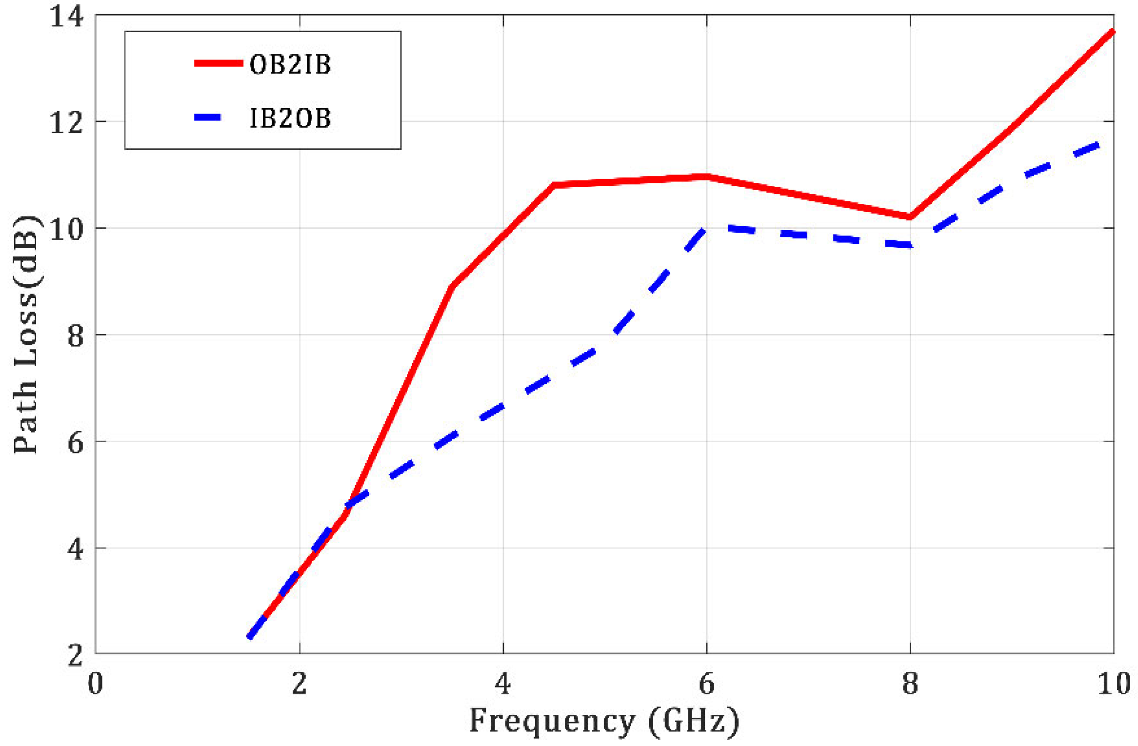
  • In-body to on-body (IB2OB) communication;
  • On-body to in-body (OB2IB) communication.
For the validation, we used COMSOL Multiphysics, which applies the finite element method. The dimensions of the proposed phantom model are 20 mm × 20 mm. The structure of human tissue consists of three layers (skin, fat, and muscle) with the same thickness as those used in the MoM method. E i = 1   V / m is the incident signal perpendicular to the skin layer.

4. Results and Discussion

4.1. Communication Scenarios

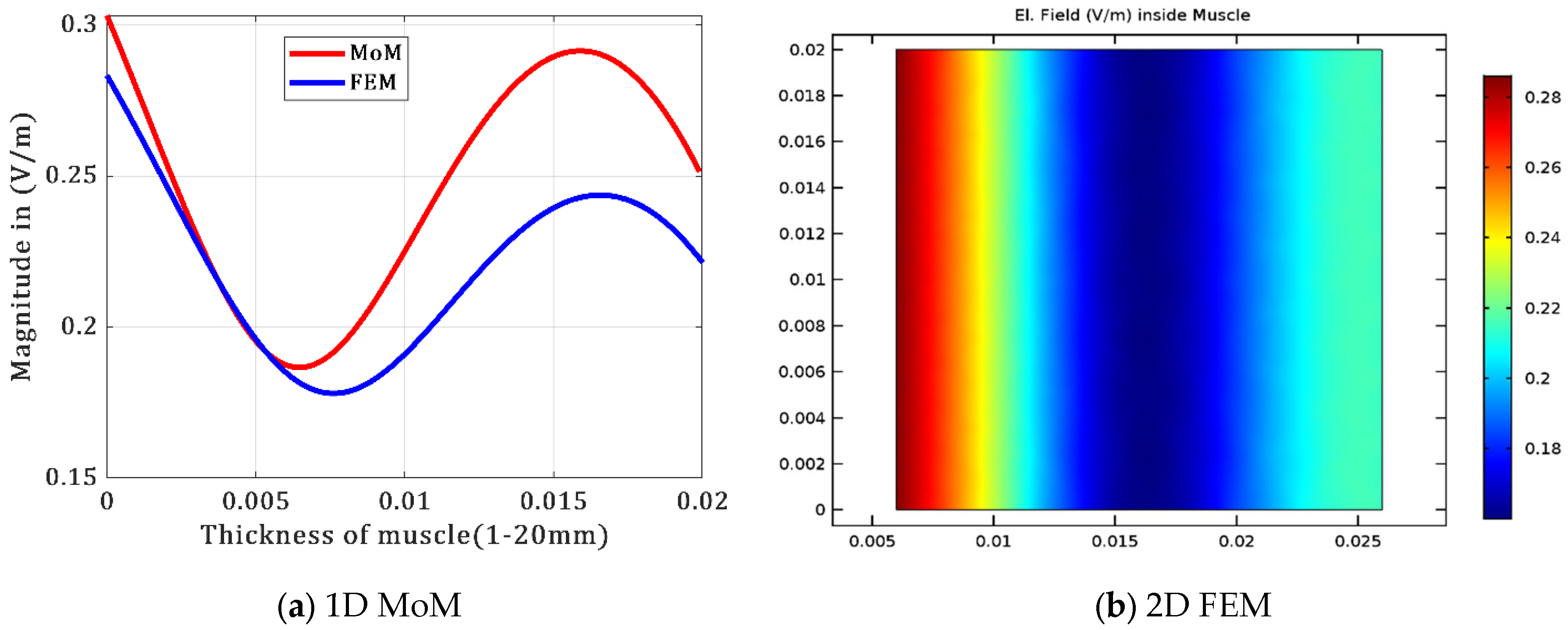
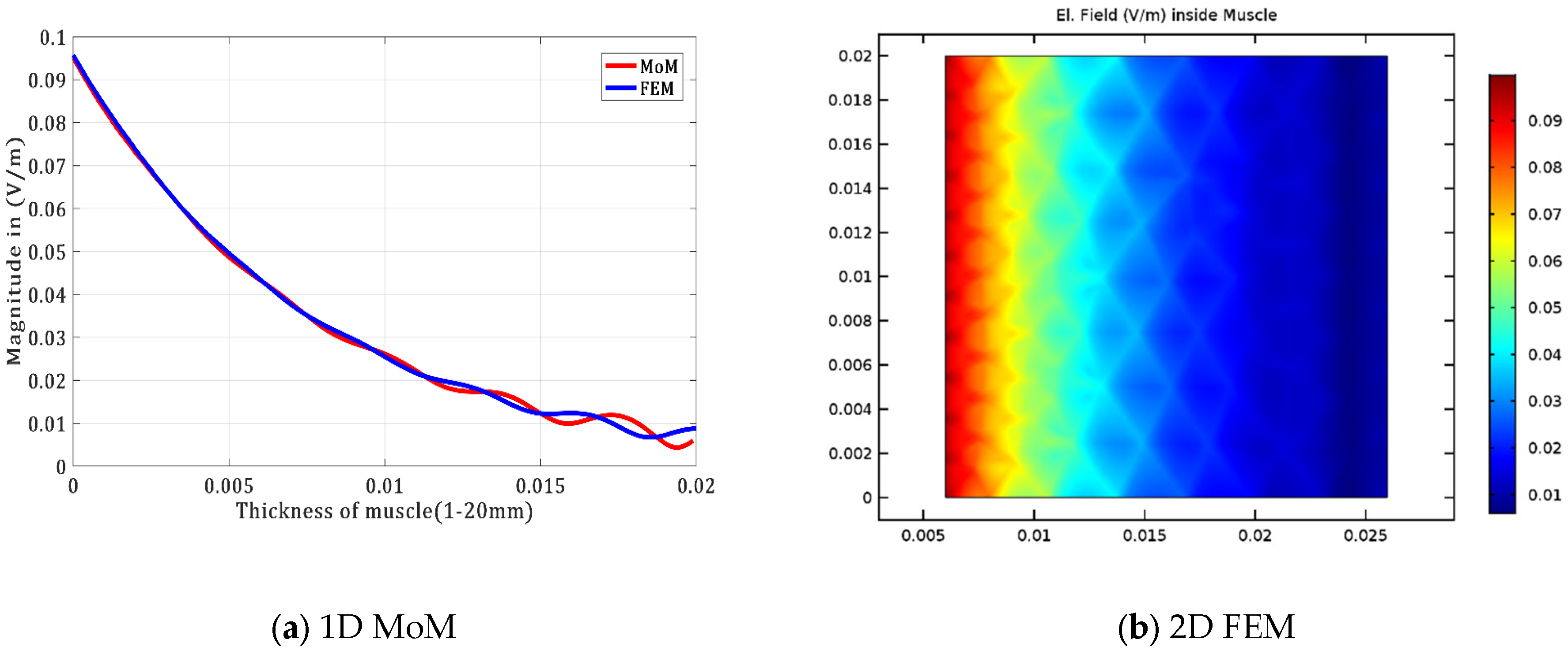
4.1.1. Communication inside Muscle Tissue

To compare the results obtained by the two methods, the dimensions and parameters of the tissues must be the same in both cases. The depths in the muscle tissue chosen for comparison were 3, 6, 9, 11, 14, and 17 mm. The magnitude of the E-field at these points has been calculated for different frequencies. For plotting the results, we should take more points, therefore, the magnitude of E-field is calculated at each 3 mm into muscle tissue. When using a plane wave with frequencies of 915 MHz and 2.45 GHz, the penetration depth of each tissue is greater than its thickness. Therefore, the wave penetrates the tissue and reflects from the next tissue, producing fluctuation at different points and forming a standing wave. Figure 4, Figure 5 and Figure 6 show the results. The comparison of the two methods at different depths and frequencies is illustrated in Table 2.
According to Equation (1), the Pd at frequency 5.8 GHz of a plane wave is 7.5413 mm. This means that the depth of penetration is less than the thickness of the muscle. As a result, the wave reflected from the bone is very small, causing exponential attenuation of the wave, especially in the region from the beginning of the muscle to a depth of 12.45 mm, as the wave behaves according to the Equation (2). In Figure 6, we can observe that the transmitted wave is much greater than the reflected wave. The case is totally different for the 12.4587 to 20 mm region, due to the wave’s behavior in Equation (3), where the reflected wave is present. Subsequently, we can conclude that in the region between 12.45 and 20 mm of muscle tissue, the E-field will present a fluctuation phenomenon. In addition, when the thickness of the tissue is smaller than the penetration depth, the wave is reflected and combined with the transmitted wave. As a result, the wave fluctuates slowly and forms a standing wave at different points. The reflected wave from the next tissue is very weak if the penetration depth of the muscle tissue is less than its thickness. This produces an exponential fading of the wave to a certain depth, at which the penetration depth is greater than the thickness. The wave fluctuates at this depth due to the presence of reflected waves.

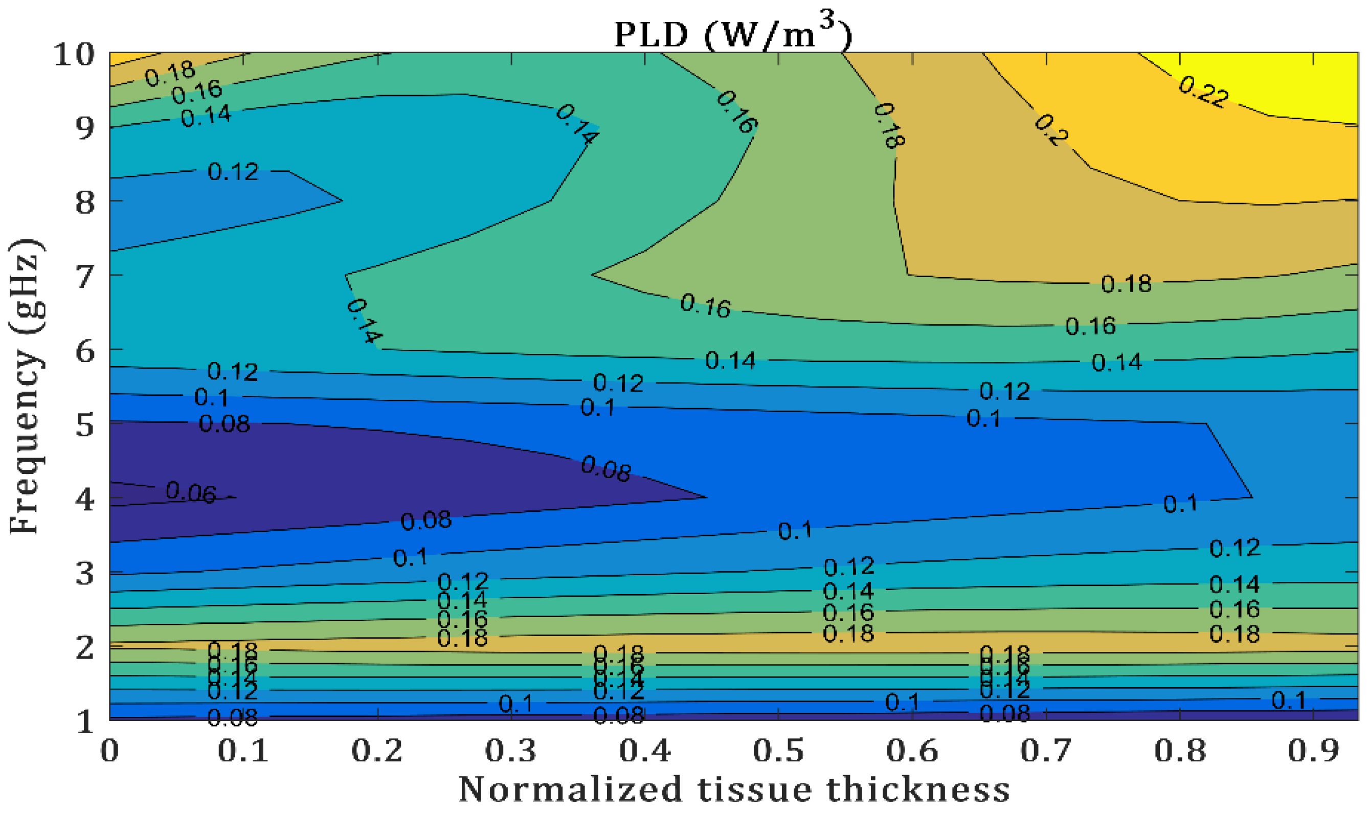
4.1.2. Communication in Inhomogeneous Human Body

The proposed model of tissue is composed of consecutive layers: skin, fat, and muscle. The MoM calculates the EM fields, Figure 7 and Figure 8 reveal the impact of the gradual alteration of medium characteristics between the layers of the human body. This gradual change in medium between layers causes minor discrimination in both electric and magnetic fields. That increases the propagation loss in the transmission channel. Furthermore, for the scenario OB2IB, the variation in the fields in the two frequencies peaks at the skin and is lowest in the muscle due to their higher electrical properties. Similarly, in the scenario IB2OB, the maximum amount of EM field is produced in the muscle and degrades slowly depending on the muscle thickness. This indicates the overall lower transmission energy at the boundaries and such attenuation is highly influenced by the dielectric properties (permittivity, conductivity) of the different biological tissues, which are frequency-dependent. As a result, we can conclude that human tissue is extremely absorbent for both OB2IB and IB2OB, which identifies the potential loss that can have a negative impact on the communication quality and that we must estimate and integrate into the channel model.
Table 3 includes the comparative results of IB2OB and OB2IB. The result of the EM field is obtained by solving Equation (25). We notice that the variation is almost similar when comparing the MoM, FEM, and [12], which strongly suggests that our results are correct and valid. Currently, all research is centered on various numerical techniques for analyzing the communication body setup. Despite its limitations, the FDTD technique is the most widely used [25]. However, we conclude in this study that MoM in the frequency domain gives good results for EM propagation inside human issues in a relatively short amount of time and with greater accuracy.

4.2. Path Loss Model

To develop a comprehensive channel model for typical implant applications, we considered IB2OB and OB2IB channel links based on different Tx locations. At each Tx location, a small antenna is inside or outside the body to transmit information. Meanwhile, the Rx was assumed on the body surface for IB2OB, and at X locations, the Rx was placed in the body. Table 4 presents an evaluation of the path loss level at different frequencies for two communication links. We can observe that for OB2IB, the PL increases as position depth increases. Likewise, a significant attenuation is visible due to the wide frequency, mainly in IB2OB. In Figure 9, the EM wave has difficulty transmitting when the frequency is higher than 10 GHz. The minimum PL occurs, and, thus, the smallest power budget is required at a frequency of about 1.5 GHz. This can be explained by the fact that the wide frequency influences the propagation channel. It should also be noted that after passing through the muscle, the EM wave decreases significantly. The main reason for this phenomenon is that the thickness and conductivity of muscle tissue are much larger than those of other tissues, and, therefore, much more loss is generated in this region.
In Figure 10 and Figure 11, the pattern of the PLD varying in different exposure cases ranging from 1 GHz to 10 GHz is depicted. The highest value of PLD is observed in the skin layer at 10 GHz. Consequently, in all cases, the maximum values of the E-field and PLD are found in the skin layer. As one moves beyond the skin, the PLD rapidly decreases, and beyond the skin, the power loss density is nearly zero, which increases the PL values in the channel modelling. This outcome aligns with the understanding that high-frequency energy absorption is concentrated on the surface of the skin, which is consistent with the fact that the energy absorbed is superficial. This phenomenon must be taken into consideration when modeling the WBAN channel communication.

5. Conclusions

Understanding the characteristics inside the human body remains a challenge for massive use in the era of WBAN communication. This work demonstrated the characteristics of inhomogeneous planar human tissue exposed to incident plane waves, based on an analytical model, by using the method of moments (MoM). All results are finally validated and compared through finite element method (FEM) computations. A comparison of both proposed methods gives, approximately, the same results. The difference in these results can be overlooked when high values of EM field are used, which confirms the potential of the MOM method for analyzing complex media. Moreover, this model enabled us to make simulations with very high precision, thus, figuring out the EM wave’s effect on planar thin layers in terms of PL and PLD. This result has important implications for practical applications of WBAN, particularly for inter-/intra-body communication links, to evaluate the performance requirements of WBANs and beyond. In future work, more complex simulations will be performed to demonstrate the ability of this method based on the MoM method to predict the specific absorption rate levels, which offer useful insight and simplify physical layer modelling for implant communication systems.

Author Contributions

Conceptualization, I.K. and S.B.M.; methodology, I.K. and S.B.M.; validation, I.K., S.B.M., S.A., F.C. and Y.M.; formal analysis, I.K. and S.B.M.; investigation, I.K., S.B.M., S.A. and F.C.; resources, S.A., F.C. and Y.M.; data curation, I.K. and S.B.M.; writing—original draft preparation, I.K. and S.B.M.; writing—review and editing, S.B.M., S.A. and F.C.; visualization, I.K. and S.B.M.; supervision, Y.M.; project administration, Y.M.; funding acquisition, Y.M. All authors have read and agreed to the published version of the manuscript.

Funding

This research received no external funding.

Data Availability Statement

Data sharing is not applicable to this article.

Conflicts of Interest

The authors declare no conflict of interest.

References

  1. Nusrat, T.; Dawod, F.S.; Islam, T.; Kunkolienker, P.; Roy, S.; Rahman, M.; Ghosh, S.; Dey, S.; Mitra, D.; Braaten, B.D. A Comprehensive Study on Next-Generation Electromagnetics Devices and Techniques for Internet of Everything (IoE). Electronics 2022, 11, 3341. [Google Scholar] [CrossRef]
  2. Costanzo, S.; Qureshi, A.M. Compact and Wideband PIFA Design for Wireless Body Area Sensor Networks. Electronics 2021, 10, 2576. [Google Scholar] [CrossRef]
  3. Li, E.; Li, X.J.; Seet, B.-C. A Triband Slot Patch Antenna for Conformal and Wearable Applications. Electronics 2021, 10, 3155. [Google Scholar] [CrossRef]
  4. Jabbar, A.; Zubair, M.; Naveed, M.A.; Mehmood, M.Q.; Massoud, Y. A photopaper-based low-cost, wideband wearable antenna for wireless body area network applications. IET Microw. Antennas Propag. 2022, 16, 962–970. [Google Scholar] [CrossRef]
  5. Movassaghi, S.; Abolhasan, M.; Lipman, J.; Smith, D.; Jamalipour, A. Wireless Body Area Networks: A Survey. IEEE Commun. Surv. Tutor. 2014, 16, 1658–1686. [Google Scholar] [CrossRef]
  6. Li, J.; Nie, Z.; Liu, Y.; Wang, L. Modeling and characterization of different channels based on human body communication. In Proceedings of the 39th Annual International Conference of the IEEE Engineering in Medicine and Biology Society (EMBC), Jeju Island, Republic of Korea, 11–15 July 2017; pp. 702–705. [Google Scholar] [CrossRef]
  7. Ben Saada, A.; Ben Mbarek, S.; Choubani, F. Antenna Polarization Impact on Electromagnetic Power Density for an Off-Body to In-Body Communication Scenario. In Proceedings of the 2019 15th International Wireless Communications & Mobile Computing Conference (IWCMC), Tangier, Morocco, 24–28 June 2019; pp. 1430–1433. [Google Scholar] [CrossRef]
  8. Ben Saada, A.; Ben Mbarek, S.; Choubani, F. Whole-Body Exposure to Far-Field Using Infinite Cylindrical Model for 5G FR1 Frequencies. In Advanced Information Networking and Applications; Lecture Notes in Networks and Systems; Barolli, L., Hussain, F., Enokido, T., Eds.; Springer: Cham, Switzerland, 2022; Volume 449, pp. 471–478. [Google Scholar] [CrossRef]
  9. Chen, Z.; Chen, X.; Lin, F.; Gong, Z. Far-field characterization of wave oblique incidence on body channel for implant communication by using an analytical model. J. Electromagn. Waves Appl. 2021, 35, 1922–1938. [Google Scholar] [CrossRef]
  10. Mercier, P.P.; Chandrakasan, A.P. (Eds.) Ultra-Low-Power Short-Range Radios; Springer International Publishing: Cham, Switzerland, 2015. [Google Scholar]
  11. Kumpuniemi, T.; Tuovinen, T.; Hämäläinen, M.; Yazdandoost, K.Y.; Vuohtoniemi, R.; Iinatti, J. Measurement-based on-body path loss modelling for UWB WBAN communications. In Proceedings of the 2013 7th International Symposium on Medical Information and Communication Technology (ISMICT), Tokyo, Japan, 6–8 March 2013; pp. 233–237. [Google Scholar] [CrossRef]
  12. Chen, Z.Y.; Gao, Y.M.; Du, M. Propagation characteristics of electromagnetic wave on multiple tissue interfaces in wireless deep implant communication. IET Microw. Antennas Propag. 2018, 12, 2034–2040. [Google Scholar] [CrossRef]
  13. Christ, A.; Klingenbock, A.; Samaras, T.; Goiceanu, C.; Kuster, N. The dependence of electromagnetic far-field absorption on body tissue composition in the frequency range from 300 MHz to 6 GHz. IEEE Trans. Microw. Theory Tech. 2006, 54, 2188–2195. [Google Scholar] [CrossRef]
  14. Khalaj-Amirhosseini, M. Analysis of Lossy Inhomogeneous Planar Layers Using the Method of Moments. J. Electromagn. Waves Appl. 2007, 21, 1925–1937. [Google Scholar] [CrossRef]
  15. Rothwell, E.J. Natural-mode Representation for the Field Reflected by an Inhomogeneous Conductor-backed Material Layer—TM Case. J. Electromagn. Waves Appl. 2007, 21, 569–584. [Google Scholar] [CrossRef] [Green Version]
  16. Sullivan, D.M. Electromagnetic Simulation Using the FDTD Method; John Wiley & Sons: Hoboken, NJ, USA, 2013. [Google Scholar]
  17. Ben Mbarek, S.; Choubani, F. FDTD modeling and experiments of microfabricated coplanar waveguide probes for electromagnetic compatibility applications. J. Electromagn. Waves Appl. 2020, 35, 634–646. [Google Scholar] [CrossRef]
  18. Krimi, I.; Ben Mbarek, S.; Hattab, H.; Choubani, F. Electromagnetic near-field study of electric probes for EMC applications. In Innovative and Intelligent Technology-Based Services for Smart Environments Smart Sensing and Artificial Intelligence; CRC Press: Boca Raton, FL, USA, 2021; pp. 45–50. [Google Scholar] [CrossRef]
  19. Carter, R. The Method of Moments in Electromagnetics, by W.C. Gibson. Contemp. Phys. 2010, 51, 183–184. [Google Scholar] [CrossRef]
  20. Happ, F.; Schröder, A.; Brüns, H.D.; Gronwald, F. A method for the calculation of electromagnetic fields in the presence of thin anisotropic conductive layers using the method of moments. In Proceedings of the 2013 International Symposium on Electromagnetic Compatibility, Brugge, Belgium, 2–6 September 2013; pp. 579–582. [Google Scholar]
  21. Sarestoniemi, M.; Hamalainen, M.; Iinatti, J. An Overview of the Electromagnetic Simulation-Based Channel Modeling Techniques for Wireless Body Area Network Applications. IEEE Access 2017, 5, 10622–10632. [Google Scholar] [CrossRef]
  22. Pellegrini, A.; Brizzi, A.; Zhang, L.; Ali, K.; Hao, Y.; Wu, X.; Constantinou, C.C.; Nechayev, Y.; Hall, P.S.; Chahat, N.; et al. Antennas and Propagation for Body-Centric Wireless Communications at Millimeter-Wave Frequencies: A Review [Wireless Corner]. IEEE Antennas Propag. Mag. 2013, 55, 262–287. [Google Scholar] [CrossRef]
  23. Carrara, N. Dielectric Properties of Body Tissues. Institute for Applied Physics; IFAC. Available online: http://niremf.ifac.cnr.it/tissprop/ (accessed on 1 December 2022).
  24. Kang, G.; Gandhi, O. Effect of Dielectric Properties on the Peak1-and 10-g SAR for 802.11 a/b/g Frequencies 2.45 and 5.15 to 5.85 GHz. IEEE Trans. Electromagn. Compat. 2004, 46, 268–274. [Google Scholar] [CrossRef]
  25. Abbasi, Q.H.; Sani, A.; Alomainy, A.; Hao, Y. Numerical characterization and modeling of subject-specific ultrawideband body-centric radio channels and systems for healthcare applications. IEEE Trans. Inf. Technol. Biomed. 2012, 16, 221–227. [Google Scholar] [CrossRef] [PubMed]
Figure 1. The relation between frequency (1000 MHz–10 GHz) and the penetration depth for different tissues [23].
Electronics 12 01282 g001
Figure 2. Propagation of the wave from lossy-to-lossy medium: fat to muscle.
Electronics 12 01282 g002
Figure 3. Propagation of the wave from air to layers equivalent to human tissue.
Electronics 12 01282 g003
Figure 4. E-field inside muscle tissue for both methods at 915 MHz.
Electronics 12 01282 g004
Figure 5. E-field inside muscle tissue for both methods at 2.45 GHz.
Electronics 12 01282 g005
Figure 6. E-field inside muscle tissue for both methods at 5.8 GHz.
Electronics 12 01282 g006
Figure 7. The EM field obtained by the MoM and FEM for OB2IB communication.
Electronics 12 01282 g007
Figure 8. The EM field obtained by the MoM and FEM for IB2OB communication.
Electronics 12 01282 g008
Figure 9. Path loss for different communication scenarios.
Electronics 12 01282 g009
Figure 10. Power loss density in skin, fat, and muscle.
Electronics 12 01282 g010
Figure 11. Power loss density only in skin.
Electronics 12 01282 g011
Table 1. Electric properties of human tissues at ISM band [23].
Frequency Tissue
Parameters
SkinFatMuscle
915 MHzε
σ   s \ m
Pd (mm)
41.33
0.87
39.95
5.45
0.05
242.3
54.99
0.94
42.1
2.45 GHzε
σ   s \ m
Pd (mm)
38
1.46
22.57
5.28
0.1
117.02
52.73
1.73
22.33
5.8 GHzε
σ   s \ m
Pd (mm)
35.11
3.71
8.57
4.95
0.29
40.48
48.48
4.96
7.54
Table 2. Comparison between two methods at different frequencies.
Depth (mm)369111417
915 MHz
MoM0.230.180.200.240.270.28
FEM0.220.170.160.210.230.24
2.45 GHz
MoM0.270.200.160.200.150.089
FEM0.230.190.150.190.130.1
5.8 GHz
MoM0.060.0430.0280.020.0160.011
FEM0.0580.0470.0330.020.0150.012
Table 3. Comparative study between calculation and simulation results on different communication scenarios at frequency of 2.45 GHz.
Communication
Scenario
Physics QuantityCalculation ResultSimulation ResultReference
OB2IBE (V/m)0.61440.5033Our work
0.597460.59853Reference [12]
H (A/m)3.3 × 10−33.8× 10−3Our work
4 × 10−34.02 × 10−3Reference [12]
PL (dB)47.6346.29Our work
IB2OBE (V/m)0.24950.2105Our work
H (A/m)4.1 × 10−34.6 × 10−3Our work
PL (dB)33.0133.15Our work
Table 4. Propagation scenarios.
Communication Scenario (dB)2.45 GHz6 GHz
OB2IB in a different muscle
position 5 mm; 20 mm
35.29; 41.3545.75; 63.87
IB2OB on the interface of the skin47.6776.24
Disclaimer/Publisher’s Note: The statements, opinions and data contained in all publications are solely those of the individual author(s) and contributor(s) and not of MDPI and/or the editor(s). MDPI and/or the editor(s) disclaim responsibility for any injury to people or property resulting from any ideas, methods, instructions or products referred to in the content.

