Article

A Multiobjective Array Beamforming Method for Arrays of Flexible Shape

1
School of Transportation and Civil Engineering, Nantong University, Nantong 266019, China
2
Department of Electronic and Electrical Engineering, University College London, London WC1E 7JE, UK
3
Department of Electrical and Electronic Engineering, The University of Manchester, Manchester M13 9PL, UK
*
Author to whom correspondence should be addressed.
Electronics 2024, 13(4), 752; https://doi.org/10.3390/electronics13040752
Submission received: 10 December 2023 / Revised: 26 January 2024 / Accepted: 5 February 2024 / Published: 13 February 2024
(This article belongs to the Special Issue Applications of Array Antenna in Modern Wireless Systems)

Abstract

:
High-performance beamforming incorporating multiple objectives for large-scale antenna arrays becomes increasingly important to improve the capacity and efficiency of wireless communication systems. The speed of synthesizing a desired beam pattern is critical in wireless communications systems to adapt to highly dynamic wireless channels. A modified particle swarm optimization (PSO) algorithm for synthesizing array beam patterns is proposed in this study. The initial positions of particles in PSO are designated following a Taylor distribution instead of being given uniformly distributed random values as in the classical PSO algorithm. The fitness functions are defined to include multiple objectives represented by producing multiple main lobes with customized deep and broadened nulls. Several scenarios have been established to examine the feasibility of the proposed algorithm. Moreover, the performance of the proposed algorithm is compared with those of the ones based on the classical PSO. A significant performance improvement for obtaining beamforming coefficients has been achieved. The robustness of the proposed algorithm is demonstrated further by applying it to a finite array on a curved surface for beamforming.

1. Introduction

Antenna arrays play an essential role in modern wireless communication systems due to their ability to provide high gain and spatial diversity, resulting in high spectral efficiency in wireless communication systems. In addition, a high signal-to-noise (SNR) ratio and low inter-user interference can be achieved by beamforming, offering high performance and flexibility [1]. Phased array antennas are critical technologies for a wide range of applications, including but not limited to radar, communication, remote sensing, navigation, radio astronomy, biomedical imaging, and radiation therapy; hence, they are widely used in many applications nowadays [2]. Multibeam antenna systems become increasingly important in many applications, including communications, imaging, and radio astronomy, in particular, the fifth-generation (5G) and beyond (i.e., 6G) wireless communications [3]. Beamforming and large-scale antenna arrays play a crucial role in many promising communication and sensing techniques towards 5G and beyond communication networks [4,5,6] such as multiple-input multiple-output (MIMO) [7], massive MIMO communications [8,9] and integrated sensing and communication systems [10].
Significant efforts are being put into exploring array antennas with low sidelobe level (SLL), high directivity, high gain, as well as increased beam steering (BS) capability [11]. In order to obtain more agile array beams and increase beam efficiency, SLL must be maintained at a low level. At the same time, placing nulls in certain directions can reject the interfering sources from the angles concerned [12].
The desired beam pattern is usually achieved by controlling the excitation coefficients of the antenna element, namely amplitude-only [13], phase-only [14], array element position-only [15], or any combination of the above parameters. Controlling a set of complex weights (both the amplitude and the phase) is the most efficient way because it has a greater degree of freedom for the solution space [16]; hence, this study aims to design the optimum complex weights in order to achieve the desired array beam pattern. A uniform linear array (ULA) is one of the most commonly used fixed-shape antenna arrays. Consequently, this article focuses on the beamforming design for ULA that suppresses the sidelobe and places nulls simultaneously.
Many algorithms have been developed for beamforming, most notably linearly constrained minimum variance (LCMV) [17], and minimum variance distortionless response (MVDR) [18]. However, these algorithms are derived based on deterministic methods. The achievable goals of these algorithms are very limited. For instance, traditional beamforming methods cannot simultaneously deal with complex scenarios, including multiple targets and specific requirements such as reducing sidelobe levels and generating nulls at specific directions.
Recently, evolutionary algorithms and machine learning techniques have also been applied to several applications of adaptive and reconfigurable antenna arrays, for instance, adaptive nulling, wireless localization, multiple-input, multiple-output (MIMO) communications, element failures, and calibration [19,20]. The evolutionary optimization algorithms are capable of solving multi-objective and nonlinear problems. These algorithms have been successfully used for antenna array pattern synthesis, such as genetic algorithm (GA) [12,20], particle swarm optimization (PSO) [21,22,23], ant colony optimization (ACO) [24], grey wolf optimization (GWO) [25], whale optimization algorithm (WOA) [26].
The PSO approach appears likely to be the most powerful. PSO is acknowledged for its fast convergence speed, fewer parameters, and ease of implementation. According to [27], PSO is more computationally effective (uses a smaller number of function evaluations) than the GA. Hence, PSO is adopted in this paper. However, the initial and convergence conditions are very important in implementing the PSO algorithm. The performance of PSO is primarily influenced by particle initialization as a stochastic search algorithm.
PSO algorithm is used for beamforming in [28] with a restrictive approach to synthesize four radiation patterns for a four-element array. An adaptive array beamformer using PSO is proposed in [29], where an initial DOA estimate is first determined using a PSO estimator to improve the overall beamformer performance. A PSO-based algorithm is utilized in [30] to address the outage problem for the millimeter-wave (mmWave) non-orthogonal multiple access (NOMA) system.
A modified PSO algorithm, which initializes particles based on a Taylor function instead of a uniform distribution, is proposed. This algorithm has a lower fitness at the beginning, and maintains a faster convergence rate in the subsequent iteration process, and is verified in the following design scenarios. The modified algorithm combines the advantages of traditional beamforming methods and intelligent algorithms, making it more suitable for solving array beamforming problems.
The major contributions of this paper are stated as follows: (1) A modified PSO is proposed with a faster convergence speed and validated and compared to the classic PSO with some typical scenarios. (2) A simple fitness function is proposed to flexibly control sidelobe level and null directions, including single null, multiple nulls, and broad nulls. (3) Considering the combination of multiple main beams and multiple nulls in large-scale arrays.
Notation: Throughout the manuscript, the following mathematical notation is used. Bold uppercase letters (e.g., H )

2. Array Beamforming

To illustrate a simple beamforming operation, consider the case shown in Figure 1. The far-field beam pattern of an antenna array can be synthesized by [31]
B θ , ϕ = w H v ( k ) ,
where w C N × 1 is a vector which represents the weights and the components are complex numbers, N is the number of elements in an array, and v C N × 1 is the array manifold vector which is related to the angle of incoming waves, determined by the wavenumber k , and the array element spacing vector p , and the observation angle θ , ϕ .
The array manifold vector v ( k ) C N × 1 is defined by
v ( k ) = e j k T p 0 e j k T p 1 e j k T p N 1 ,
which incorporates all of the spatial characteristics of the array. The array consists of a set of isotropic antennas located at positions p n = p x n , p y n , p z n T , n = 0 , 1 , , N 1 . Moreover, the wavenumber is defined by
k = 2 π λ sin θ cos ϕ sin θ sin ϕ cos θ ,
where λ is the wavelength. The complex weight vector is w H = w 0 * , w 1 * , , w N 1 * , which can adjust the gain and phase at the output of each antenna to achieve a desirable beam pattern.
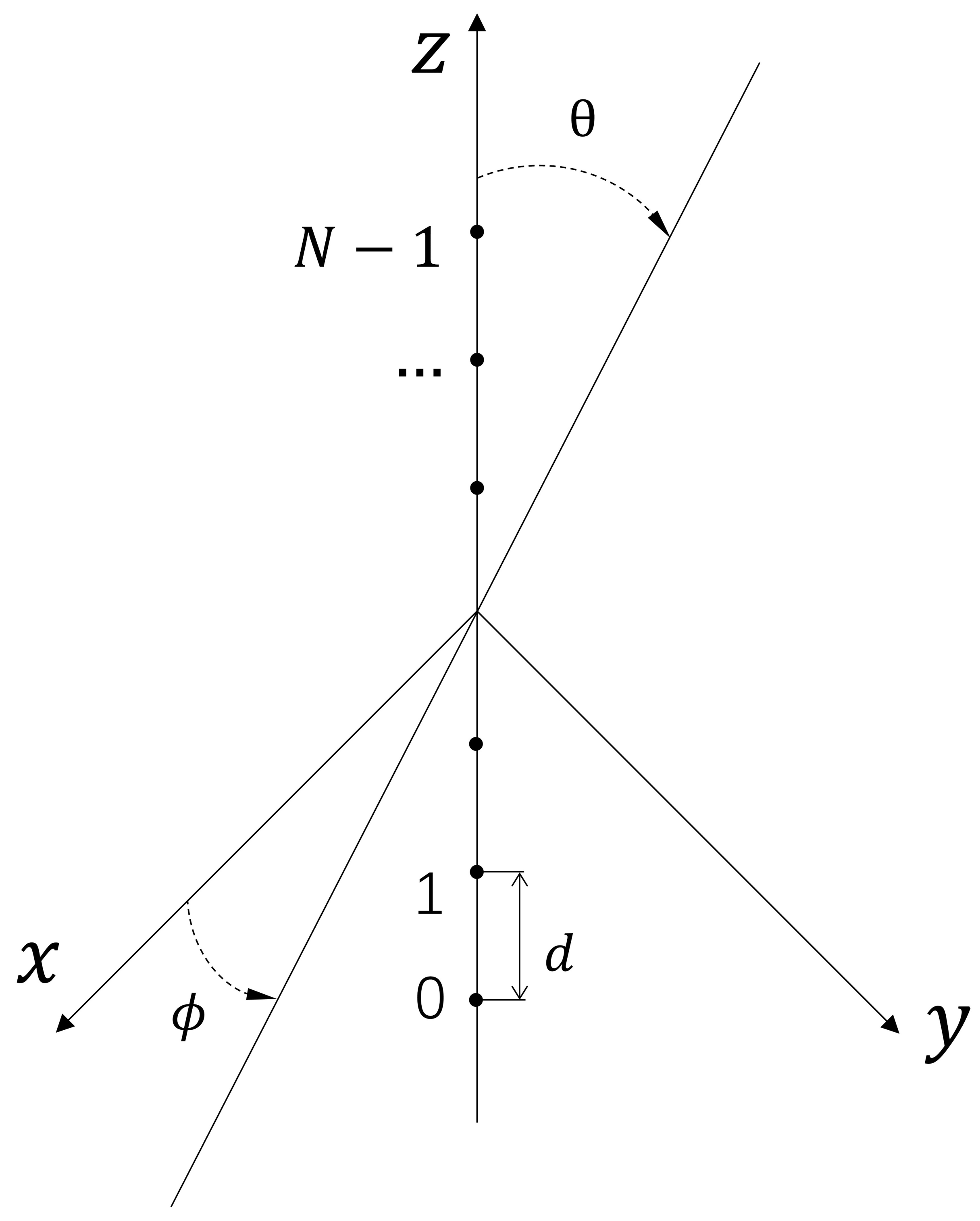
A uniform linear array has been chosen as an example to examine the algorithm proposed in this work, as the algorithm proposed can be easily implemented for other array configurations without much modification. The ULA of interest is shown in Figure 2, which consists of N antennas located on the z-axis with uniform spacing equal to d, and the center of the array is placed at the origin of the coordinate system.
The locations of the array elements are:
p z n = n N 1 2 d , n = 0 , 1 , , N 1 ,
where, p x n = p y n = 0 . The beam pattern of the ULA can be written in the following form:
B θ = w H v θ = e j N 1 2 2 π d λ n = 0 N 1 w n * e j n 2 π d λ cos θ .
Substituting cos θ with cos θ cos θ 1 in (5), and the array vector expression gets modified, the modified ULA beam pattern expression is shown in (6)
B θ = w H v 1 θ = e j N 1 2 2 π d λ cos θ n = 0 N 1 w n * e j n 2 π d λ cos θ cos θ 1
where θ 1 is steering angle and beam pattern B θ has its maximum when θ = θ 1 .
The beam pattern of ULA with multiple beams was synthesized by adding multiple array vectors steering at different directions.
B θ = w H i = 1 K v i θ = i = 1 K e j N 1 2 2 π d λ cos θ n = 0 N 1 w n * e j n 2 π d λ cos θ cos θ i
where v i θ is the ith array vector corresponding to the ith steering angle θ i , K is the number of main beams. The normalized array beam pattern in dB can be expressed as
B θ dB = 20 log 10 B θ max B θ
In this study, the weights vector, w , consisting of complex values to steer the array beam, needs to be optimized according to (5)–(7) to fulfill the objectives of achieving several peak values for main lobes and desired nulls in the synthesized array pattern, whereas the sidelobe level remains below a specific target value. When the number of array elements increases to a large number, the computation complexity of forming the desired beam pattern becomes significantly high. Hence, it is necessary to develop efficient and low-complexity techniques.

3. Beamforming Algorithms

3.1. Problem Description

Conventionally, array steering vectors (i.e., weights applied for beamforming) are calculated using deterministic methods where the values of interest can be derived from the requirements. For multiobjective problems such as the ones described in this work, these methods become inefficient or even impractical. Hence, intelligent algorithms based on population evolution are introduced for more complex problems. PSO demonstrates its merit, among others, due to its high efficiency in dealing with sophisticated multiobjective problems with limited computational resources.
To solve optimization problems incorporating a large number of variables, such as designing a sophisticated target beam pattern based on a large-scale antenna array system, PSO can be effectively utilized. The objective of the optimization task is represented by a fitness function, which is to be minimized in the process. Consider a fitness (or cost, error, objective) function: f ( x ) , which incorporates and defines the problem that needs to be solved. The general problems in question for PSO algorithms can be described by optimizing x , which satisfies.
min x f x , s . t . l d x d u d , d = 1 , 2 , , D ,
where x = x 1 , x 2 , , x D is the optimal solution in a vector form and D is the dimension of solution. Each x d is bounded by lower limits l d and upper limits u d .

3.2. Classical PSO

3.2.1. Particle Swarm Optimization

PSO algorithm is an evolutionary optimization technique inspired by the behavior of birds in a swarm, which was initially proposed by Eberhart and Kennedy [32], and later modified and further improved by Shi [33].
In PSO, each potential solution to the optimization problem is a particle in the search space. All particles have a fitness function value determined by the problem to be optimized, and each particle has a velocity vector to determine its “flying” direction and distance. The movement of each particle is then determined after searching through the workspace by combining some aspect of the history of its own current and best (best-fitness) locations with those of one or more members of the swarm, adopting some random perturbations. The following iteration takes place after all particles have moved. Eventually, the swarm as a whole, like a flock of birds, is collectively foraging for food.
The position of the ith particle is a D-dimensional vector. The ith particle is represented as x i = ( x i 1 , x i 2 , , x i D ) . Each particle has its corresponding velocity vector v i = ( v i 1 , v i 2 , , v i D ) . The best position for the ith particle in the current iteration is pbest i = ( p i 1 , p i 2 , , p i D ) , and the best position after search for the whole particle swarm is gbest = g 1 , g 2 , , g D . All particles update their position and velocity in every iteration according to the following formula [33]:
v i d = w * v i d + c 1 * r 1 p i d x i d + c 2 * r 2 g d x i d x i d = x i d + v i d .
The particles search the whole space and update their values until the fitness function satisfies a target error defined in the optimization problem.

3.2.2. Parameters in PSO

The key parameters used in the PSO algorithm are described as follows:
  • Inertia weight, w, which is linearly decreasing with the iteration number, is defined as,
    w = w max w max w min T max t ,
    where w max is the maximum inertia weight and w min is the minimum, typically w max = 0.9 and w min = 0.4 ; t is current iteration number; T max denotes the maximum number of iterations designated in the algorithm.
  • Two random parameters, r 1 and r 2 are uniformly distributed values in the interval 0 , 1 .
  • Acceleration constants, c 1 and c 2 are set equal to 2; they work well for most of the applications. This has been proven by previous work [34]. However, the value of 1.49 was assigned to both parameters in certain cases [35].
  • Swarm size, Pop _ size is also named population size or the number of particles, which is usually set between 70 and 100 to be safe. For higher-dimensional problems, PSO often demonstrates a better performance with a larger swarm size [36].

3.2.3. Position and Velocity Initialization

As an iterative algorithm, in the beginning, initial values are given to the positions and velocities of particles, and they play a decisive role in reaching the convergence for the PSO algorithm. The positions of particles are initialized so that they spread among the entire search space [37], ensuring uniform coverage within the search domain and avoiding a local convergence, moreover, leading to a relatively high convergence speed. Another good strategy for initializing the velocities is to set them to zero or random values close to zero instead of giving uniformly distributed random values [38].

3.2.4. Position and Velocity Bounds

Owing to the stochastic nature of updating velocities in iterations, it is possible that the trajectory of a particle expands out of the parameter space, eventually crossing the boundaries of the search space. The method to overcome this problem is to adopt velocity clamping [39], a technique that limits each particle’s velocity; at the same time, the positions of particles are also constrained within a specified range. These boundaries are applied to prevent particles from moving beyond the limits of the search space.
The velocity and position limitations are applied as,
v i , d t = v d max , v i , d t > v d max v d max , v i , d t < v d max v i , d t , otherwise
and
x i , d t = u d , x i , d t > u d l d , x i , d t < l d x i , d t , otherwise ,
where v d max and v d max are the upper and lower bounds of the velocity of the dth component, u d and l d are the upper and lower bounds of the positions of the dth component. The PSO using the above parameter settings and strategies is named “Classical PSO” in this work, and it will be compared in the beamforming application with the “Modified PSO”, which is proposed in the work.

3.3. Modified PSO Algorithm

3.3.1. Establishing Initialization Strategy

In implementing “Classical PSO”, the particle initialization step is often overlooked, especially for some applications. In fact, most work gives randomly generated, and uniformly distributed values for the initial particle coordinates [40]. This could lead to redundant iterations and poor performance. A novel particle initialization strategy has been proposed in this work, which can improve the search performance in the case of a large number of parameters for beamforming. The proposed method is named Modified PSO in the following sections.
In PSO, the basic principle of initializing particle positions is to make them cover the entire search space, which can improve the likelihood of achieving the global optimal solution. It is worth mentioning that while ensuring particle diversity, initializing the particle positions with the proposed method yields a better convergence and also significantly reduces the search time for the optimum solution.
One of the key objectives of this study is to obtain the SLL below a specified value rather than simply reducing sidelobes without a goal. Taylor proposed a beamforming technique, also known as Taylor distribution [41], that can put constraints on the maximum sidelobe level and obtain gradually decreasing sidelobes. Using the Taylor distribution to initialize the particle positions, the PSO algorithm can produce a better fitness value because it can satisfy one of the multiple targets at the beginning by suppressing sidelobes. Initializing particle positions with nominal Taylor weights can lead to rapid convergence while ensuring population diversity and avoiding falling into local minima.
The procedure of initializing particle swarm positions is summarized as follows:
  • First, work out the weights w t a y l o r = w 1 , w 2 , . . . , w N following a Taylor distribution, the entries required comprise the total number of array elements and the desired peak sidelobe level;
  • Obtain the initial particle positions by adding the Taylor weights with random values, and the calculation is described in detail in the following section;
  • Assemble the particle swarm using the initial particle positions, ready to carry out the optimizing iterations.
It should be noted that the element in the vector consisting of values generated with the Taylor distribution is real, whereas what is required for beamforming is complex weights. Hence, a transformation was carried out, and the real and imaginary parts of the particles were acquired by incorporating Taylor weights as shown in (14).
The initial position of each particle, represented by x i , with its elements being complex value, are acquired by:
x i d = ( w d + r 4 ) + j ( w d + r 3 ) ,
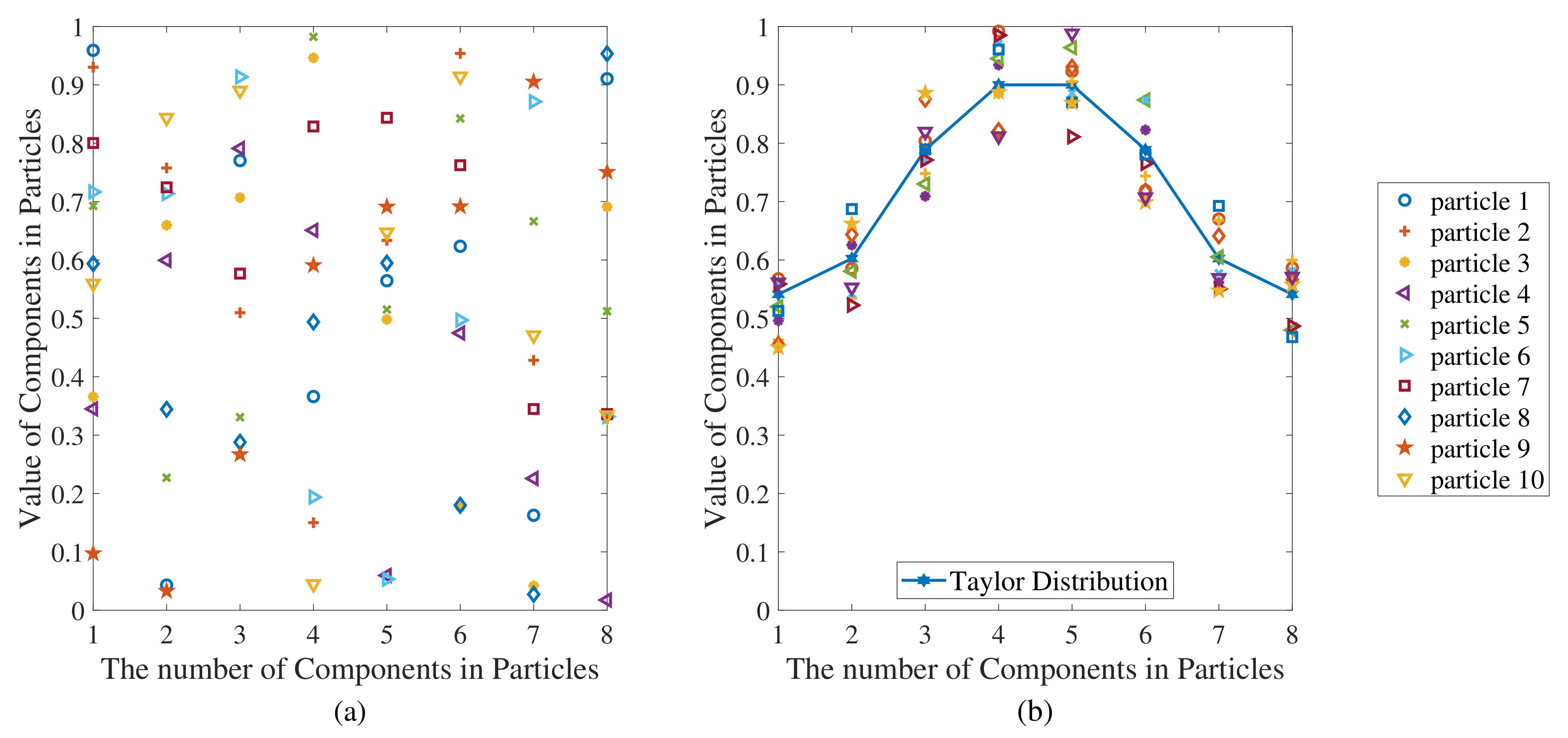
where x i = ( x i 1 , x i 2 , , x i D ) and x i d is its dth dimensional component, w d is the d-dimensional component of w t a y l o r , d = 1 , 2 , , N , j = 1 , r 3 and r 4 are representing random values added to the fixed weights following the Taylor distribution. The range of the values for r 3 and r 4 was optimized. When the range is too large and close to half of the peak value of Taylor Weights, the benefit of adopting the Taylor distribution tends to disappear; when the range is too small, the difference between different particles is very small, and the algorithm is prone to falling into local convergence; hence the recommended range was taken at 0.1 , 0.1 .
The initial particle positions generated for the classic PSO (random values following a uniform distribution for each element in the particle vector) and for the proposed PSO in this study, generated from a Taylor distribution, are given in Figure 3. To visually demonstrate the initial value distribution of particles using two initialization strategies, Figure 3 uses a simplified case study. In Figure 3, the number of antenna units is eight, and the number of particles is ten. A particle as a set of weights has only the real part; the value of particles is limited to [0,1]; the range of random values added to the Taylor weights is 0.1 , 0.1 .
The proposed initialization strategy is based on the Taylor distribution, which can also use the Chebyshev distribution since it can specify the maximum level of sidelobes. The initialization based on the Chebyshev distribution follows the same steps given above.
A general beamforming case (where one main beam has a few nulls and low sidelobes) is considered to investigate the impact of different initialization particle strategies on the overall performance of the PSO algorithm. The comparison results are shown in Figure 4, which clearly demonstrates that the algorithm using a Taylor distribution-based initialization strategy provides the most effective performance, yielding a better (i.e., lower) fitness value under the same number of iterations. This advantage applies to more general cases.
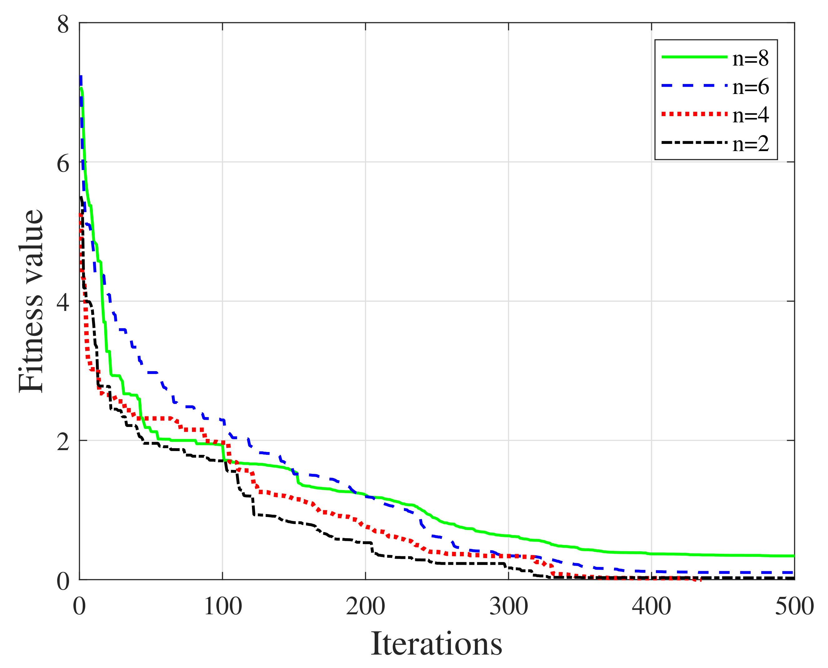
When giving values for initializing positions using the Taylor distribution, n is an indicator number of nearly constant-level sidelobes adjacent to the main lobe, specified as a positive integer [41]. The selection of this parameter will also have a slight impact on the algorithm. We also used the same beamforming case to investigate the impact of the value n on different algorithms. The converging process for adopting Taylor weights using different n are given below. As shown in Figure 5, the convergence performances of different values of n are very close. However, the cases with smaller values (2 and 4) perform better in reaching the convergence.

3.3.2. Procedure for the Modified PSO

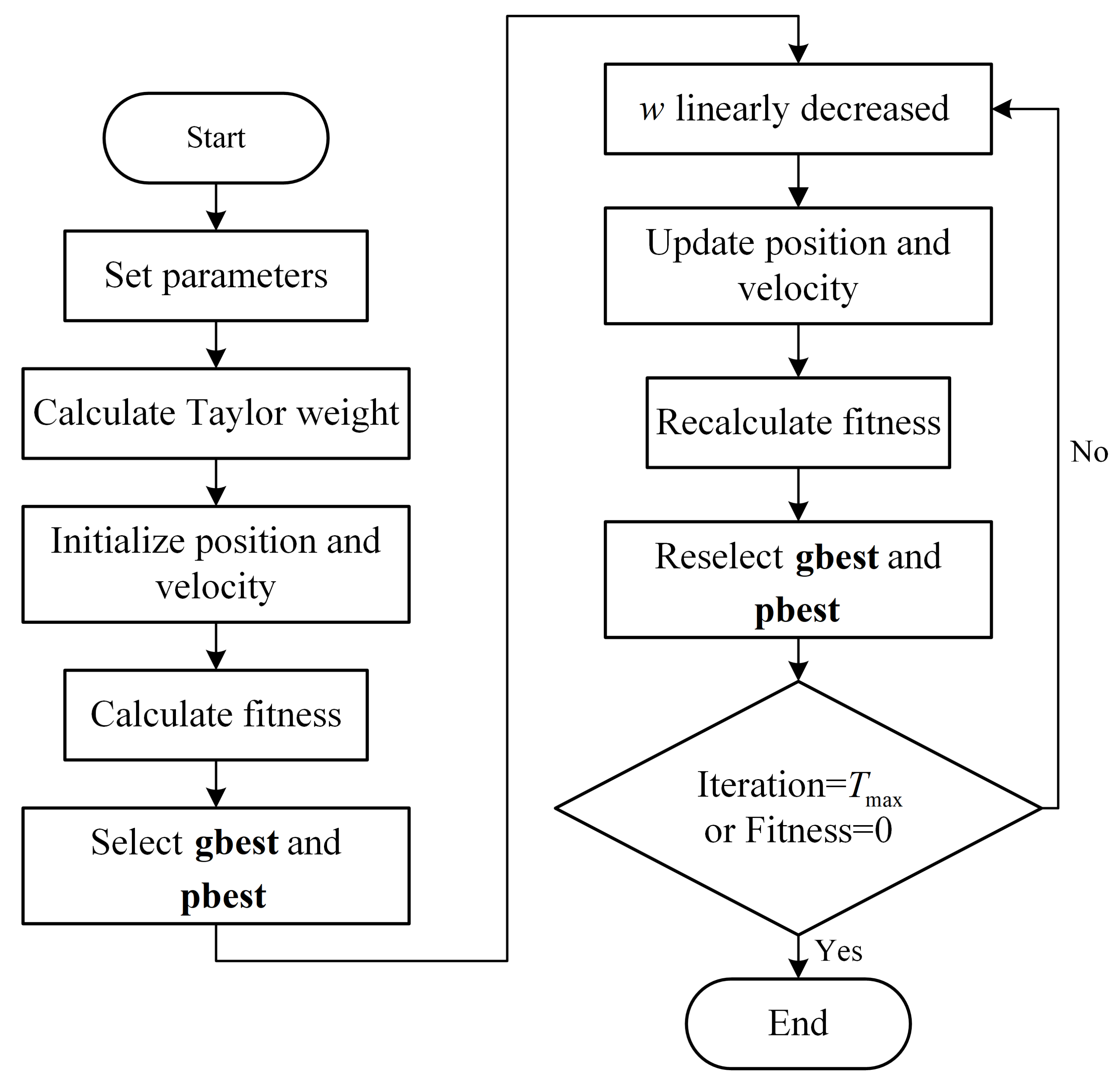
The proposed algorithm uses a new initialization particle strategy, while other parameters related to the PSO remain unchanged. The main steps of the proposed PSO algorithm with the new initialization strategy are shown in Figure 6. Furthermore, the pseudo-code of the algorithm is given in Algorithm 1.
Algorithm 1: Modified PSO
Input: array elements N, Pop _ size , T max , fitness function f i t , position upper bound u 1 , u 2 , , u D , position lower bound l 1 , l 2 , , l D ,
Output: Optimized gbest
1:
w = 0.9 ;   c 1 = c 2 = 2 ;
2:
calculate w _ t a y l o r ;
3:
for i = 1: Pop _ size do                                ▹ Initialize particle
4:
    for d = 1:D do
5:
         x i d = ( w d + r 4 ) + j ( w d + r 3 ) ;
6:
         v i d = 0 ;
7:
         p b e s t i d = x i d ;
8:
    end for
9:
end for
10:
choose gbest ;
11:
t = 0 ;
12:
repeat                                       ▹ Main loop
13:
     t = t + 1 ;
14:
     w = 0.9 ( t 1 ) * ( 0.9 0.4 ) / ( T max ) ;
15:
    for i = 1: Pop _ size  do
16:
        for d = 1:D do
17:
            v i d = w * v i d + c 1 * r 1 * ( p b e s t i d x i d ) + c 2 * r 2 * ( g b e s t d x i d ) ;
18:
            x i d = x i d + v i d ;
19:
        end for
20:
        if  f i t ( x i ) < f i t ( pbest i )  then
21:
            pbest i = x i ;
22:
           if  f i t ( pbest i ) < f i t ( gbest i )  then
23:
                gbest i = pbest i ;
24:
           end if
25:
        end if
26:
    end for
27:
until  t = T max or f i t ( gbest ) = 0
28:
return  gbest

3.4. Fitness Function Definition

The fitness function defines the convergence requirement of satisfying the objective such that the positions of all particles are optimized. For beamforming problems, we are generally interested in achieving a desired beam pattern, including a low sidelobe level, several beams, and nulls at specified angles in the synthesized far-field radiation patterns. Meanwhile, the depth and width of nulls may also need to be managed. The fitness function f, which incorporates multiple goals to achieve, is defined as
f = 0.8 * f 1 + 0.2 * f 2 , WHERE f 1 = MSLL DSLL if MSLL > DSLL 0 if MSLL DSLL , f 2 = MNDL DNDL if MNDL > DNDL 0 if MNDL DNDL ,
where MSLL denotes the peak sidelobe level of the array pattern that is calculated from particles in each iteration (the particle vector is assigned with a set of weights) using (4), DSLL denotes the desired peak sidelobe level, MNDL denotes the calculated maximum value of radiated powers in the directions where nulls are expected, and DNDL denotes the desired power level for nulls. One or multiple nulls can be synthesized using this fitness function.
The optimized values for MSLL and MNDL are obtained once they are smaller than the target values, DSLL and DNDL . The iterations for optimization stop when the value of the fitness function converges to 0, which is determined by a condition for convergence.

4. Numerical Analysis

In order to demonstrate the performance of the proposed PSO technique, beamforming design and synthesis problems with sophisticated requirements have been considered. In simulations, we have used MEEP for electromagnetic simulations and Python to run PSO-based optimizations and system simulations. Five typical scenarios of array beamforming are investigated. The specific requirements and settings of the five scenarios are summarized in Table 1. These five scenarios are grouped into two categories, described and studied in Section 4.1 and Section 4.2. Section 4.3 compares the results from the proposed method to the ones obtained based on the classic PSO. In addition, the influence of different SLL and null requirements on beamwidth was studied in Section 4.4.

4.1. One Main Lobe

The beam patterns with one main lobe were considered in this category. The main lobe was assumed in the direction where θ = 90 , and several extra requirements on nulls were investigated by incorporating them in the objective functions.

4.1.1. Single Null

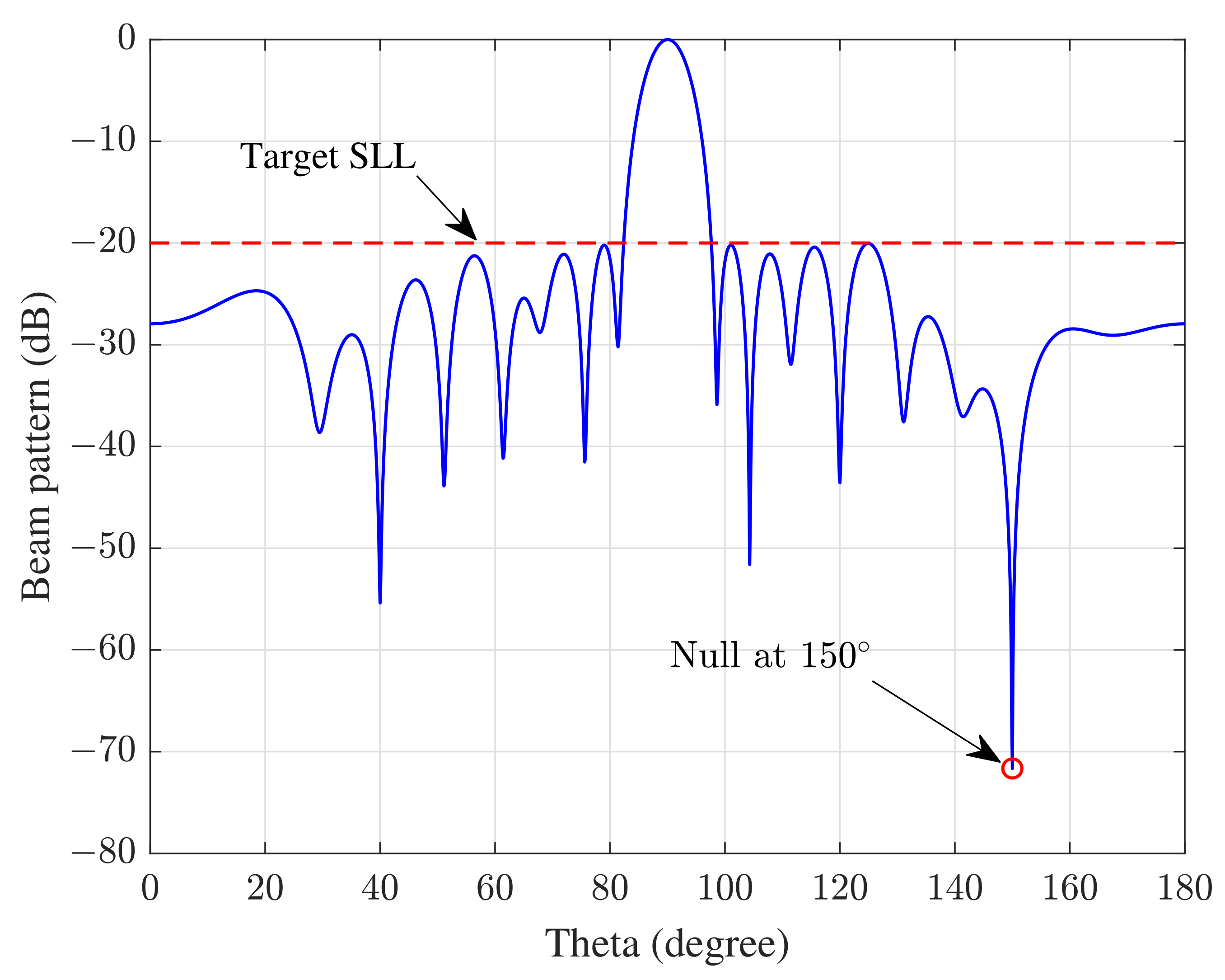
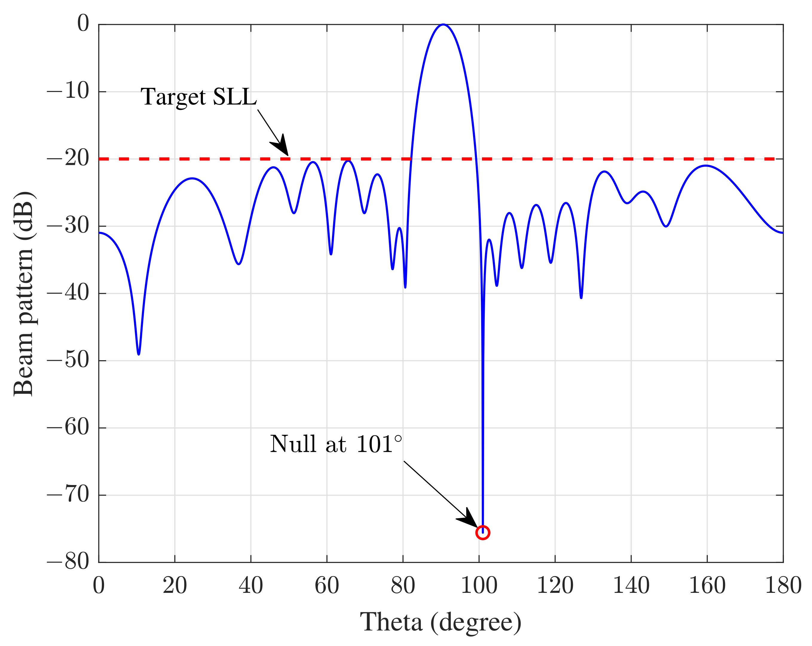
In scenario 1, one main lobe in the radiation pattern with a single null is studied. The direction for the null can be arbitrarily set at any angle (except for the main lobe direction). In the first trial, it is set with θ = 150 and θ = 101 . A null near the main lobe is set to demonstrate the algorithm’s agility to place the null at an arbitrary angle. The target sidelobe level (SLL) and null depth level (NDL) are −20 dB and −70 dB, respectively.
After implementing the algorithm for an array of 16 elements as defined for Scenario 1, Figure 7 and Figure 8 show that the null in the specified direction is obtained. Meanwhile, SLL is maintained at a relatively low level. The NDL of the prescribed angle and peak SLL are −71.65 dB and −20.04 dB in Figure 7, and in Figure 8 they are −75.57 dB, −20.26 dB, respectively. The Beam Width between First Nulls (FNBW) in Figure 7 and Figure 8 are 17.2 degrees and 19.4 degrees. The difference in FNBWs for the two null configurations is 2.2 degrees.

4.1.2. Multiple Nulls

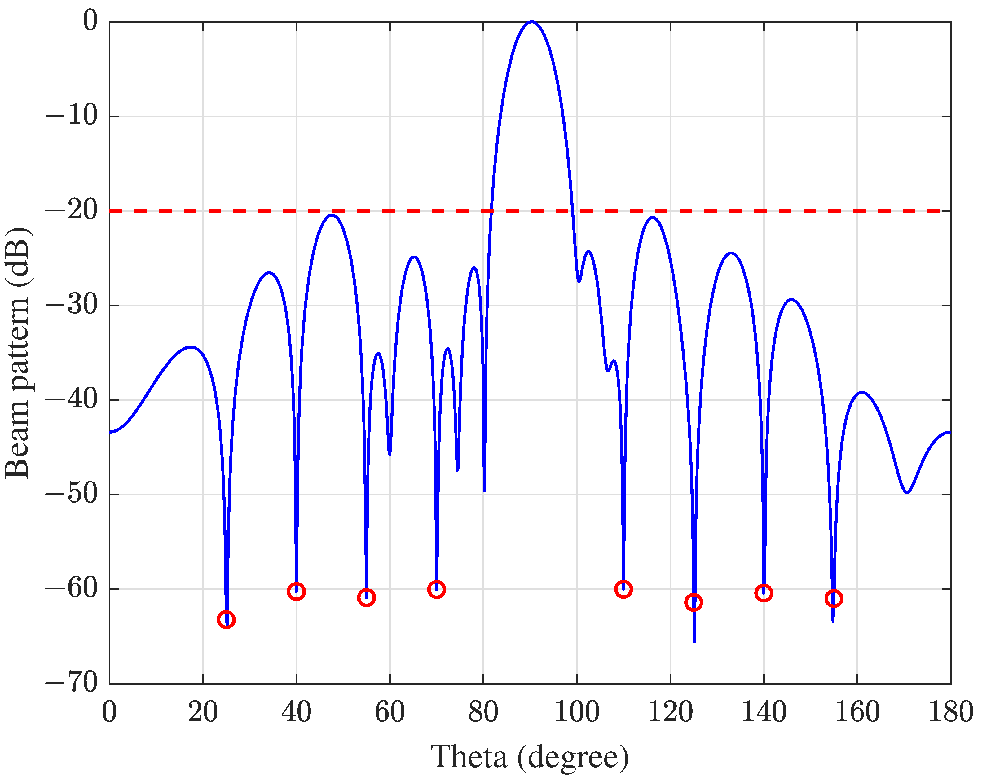
In Scenario 2, one main beam with multiple nulls is considered. Initially, the directions for eight nulls were set for the array with 16 elements at 25 , 40 , 55 , 70 , 110 , 125 , 140 , and 155 .
After performing the algorithm with the new fitness function, as shown in Figure 9, the synthesized beam pattern with a low SLL and eight nulls at predefined directions has been obtained. The peak SLL was −20.44 dB, the FNBW was 15.0 degrees, and the depths of all eight nulls at their specified angles were summarized in Table 2. The target SLL and NDL are −20 dB and −60 dB, respectively. Moreover, all NDLs were below −60 dB as desired.

4.1.3. Broad Nulls

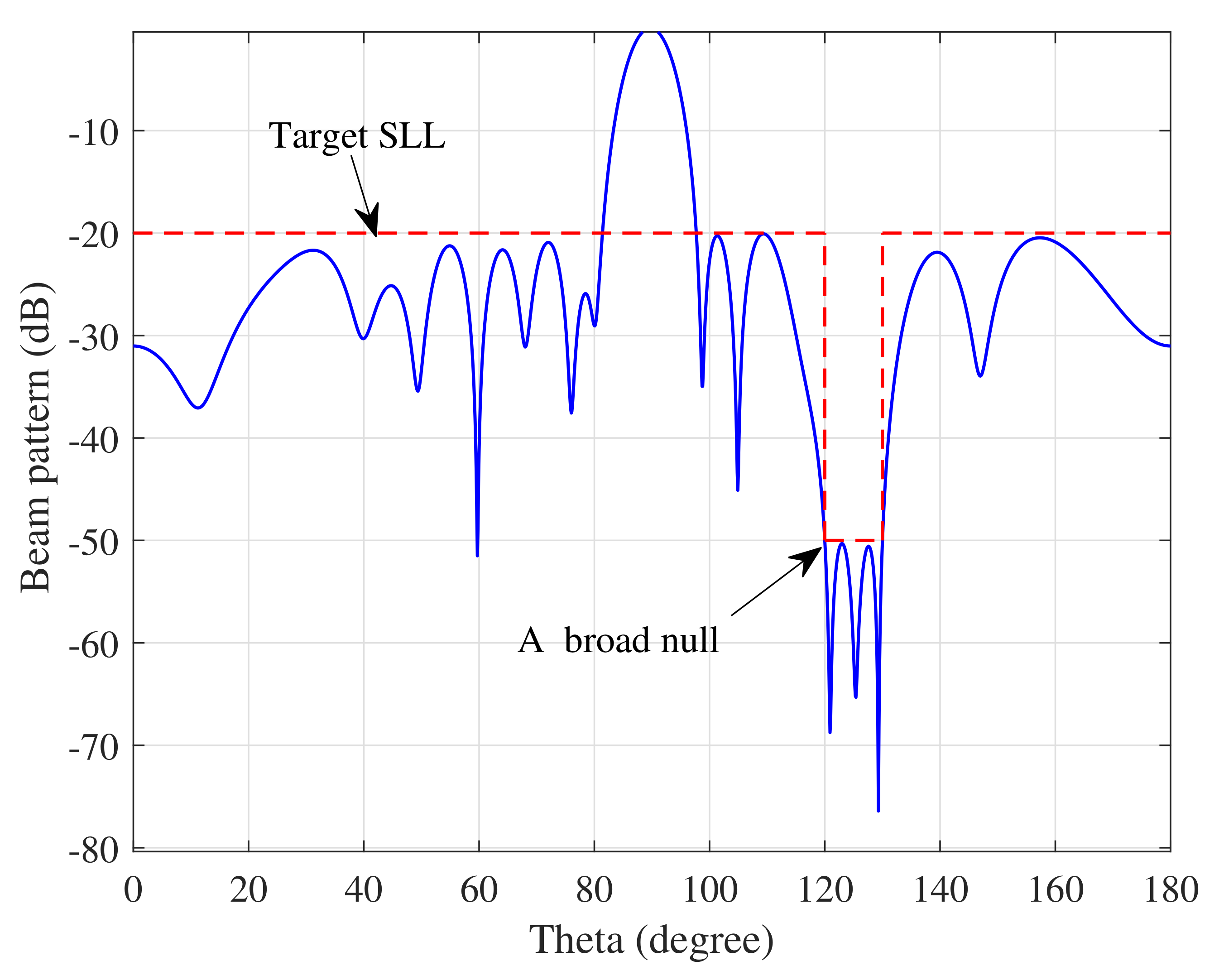
A broad null is sometimes required if the interfering signal’s direction of arrival (DOA) cannot be estimated exactly. To demonstrate the capability of the algorithm to suppress the interference from a range of angles, scenario 3 is considered; the range of angles for the interfering source is set in 120 , 130 , the target SLL and NDL is −20 dB and −50 dB, respectively. After implementing the algorithm, the synthesized beam pattern with a broad null as deep as −50 dB, an FNBW of 15.0 degrees and a peak SLL of −20.08 dB have been demonstrated, which was illustrated in Figure 10.

4.2. Multiple Beams

Multiple beams are required in some applications such as radio astronomy; more than one beam pointing to different angles simultaneously is expected to accelerate the survey speed; meanwhile, a number of nulls are produced to reject interfering sources. In scenarios 4 and 5, the proposed algorithm was implemented to synthesize multiple main lobes, whereas more than one null was anticipated.

4.2.1. Two Main Lobes

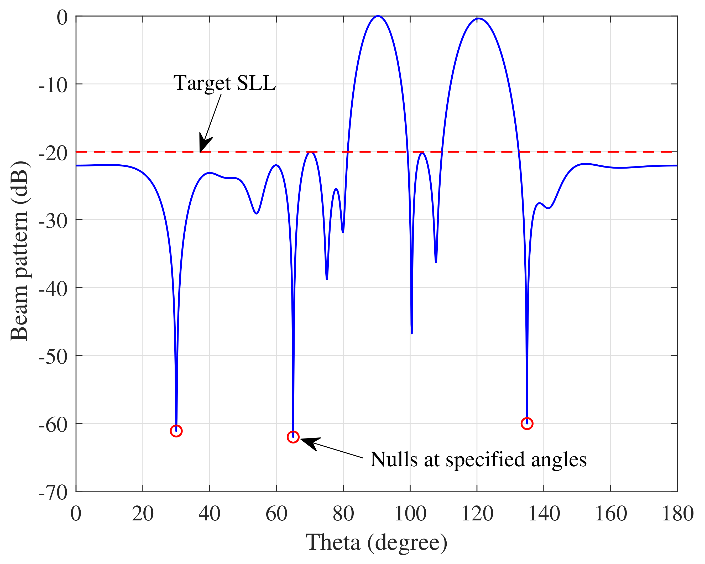
An array beam pattern with the main lobes pointing to 90 and 120 can be calculated using (4). In scenario 4, the angles for nulls are designated at 30 , 65 , 135 , and the target SLL and NDL were set as −20 dB and −60 dB. As shown in Figure 11, the beam pattern with three nulls and two beams at their predefined directions has been obtained. The peak SLL is −19.97 dB, the FNBW for the first main lobe is 20.6 degrees, the FNBW for the second main lobe is 27.3 degrees and the depth for the nulls at the directions of 30 , 65 and 135 are −61.13 dB, −62.02 dB and −60.04 dB, respectively.

4.2.2. Thirteen Main Lobes

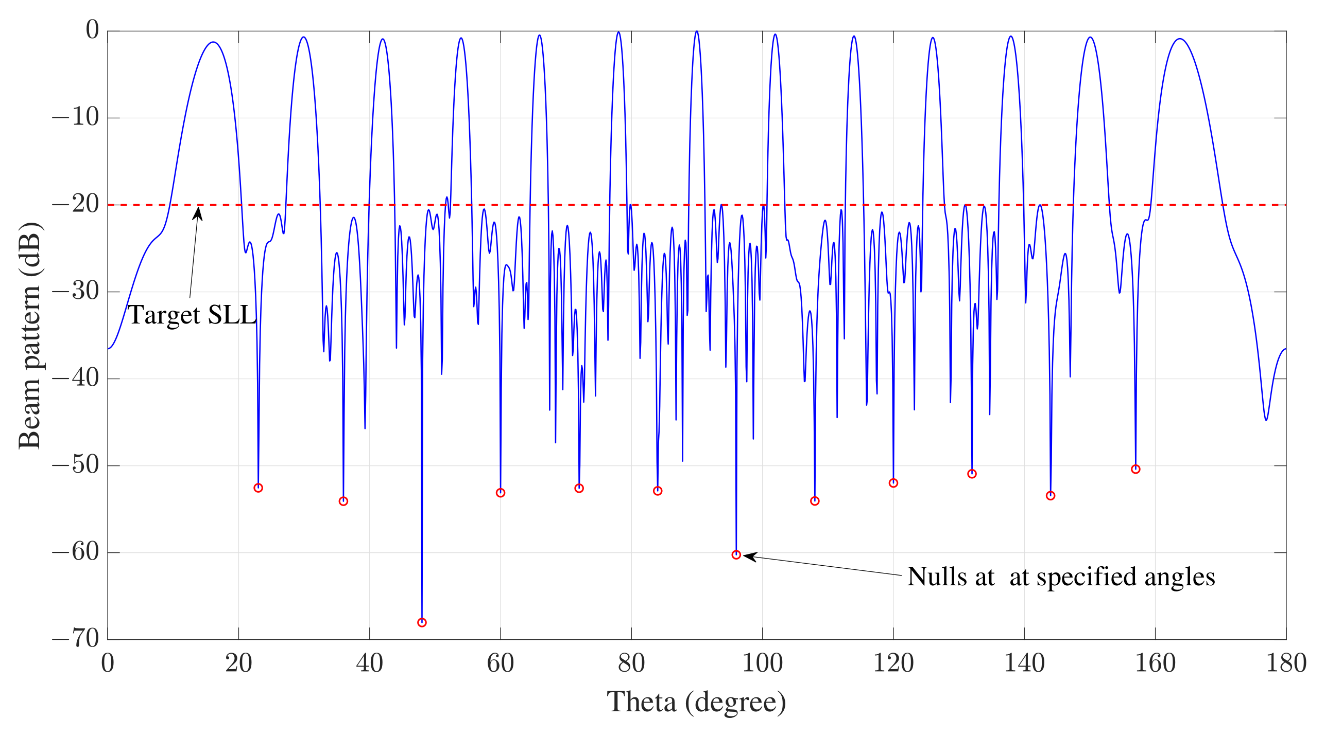
In order to evaluate the full potential of the proposed algorithm for beamforming, in Scenario 5, an array with 100 elements was studied, where 13 main lobes and 12 nulls were expected to be formed. As the requirement is much more stringent than the previous ones, −50 dB was assigned for the target level of nulls. However, the SLL maintained 20 dB lower than the main lobe.
Due to the increase in the dimensions of the problem to be optimized, the Pop _ size and T max were set to 1000 and 1000, respectively, when using the proposed PSO. After implementing the algorithm with the new fitness function, the synthesized pattern with the 13 main lobes and 12 nulls is achieved, and this was illustrated in Figure 12, the peak SLL was −20.27 dB, and the power levels for the 12 specified angles of nulls were summarized in Table 3.

4.3. Modified PSO versus Classic PSO

Finally, the effectiveness of the proposed modified PSO was evaluated by comparing it with the Classic PSO. The evaluation was performed for all scenarios except scenario 5, as it is too complicated for the classic PSO. The shared values of parameters for implementing the Modified PSO and Classic PSO are given in Table 4 for 4 scenarios investigated, and the performance of searching for both methods was obtained and then compared by adopting the values given in Table 4.
The gradual change of fitness function values during the optimization iterations for scenarios 1 to 4 is illustrated in Figure 13. They were calculated by averaging over 10 repeating runs for each curve independently. The final average fitness value is shown in Table 4, where T max is the number of iterations per run. From Figure 13 and Table 4, it can be seen that the proposed algorithm yielded lower fitness values in the early stage of iterations and reached convergence more efficiently under all scenarios of investigation.
The optimal complex weights meeting the desired objectives for the four scenarios were obtained by running the two algorithms, and they are given in Table 5.

4.4. Beamwidth

The beamwidth is another important factor to consider for beam pattern synthesis. It includes Half-Power Beam Width (HPBW) and FNBW. The characteristics of both of them were studied for the cases with various null requirements. After implementing the modified PSO on the array of 16 elements, the FNBW and HPBW produced with different SLLs and null requirements are shown in Table 6. Only one null was considered here, and the desired null depth is below −60 dB. From Table 6, it can be seen that lower nulls resulted in wider FNBWs. For the HPBW parameter, it stayed nearly constant for the three cases where the null was formed at 135 , 85 , and 20 , respectively.

5. Results and Discussion

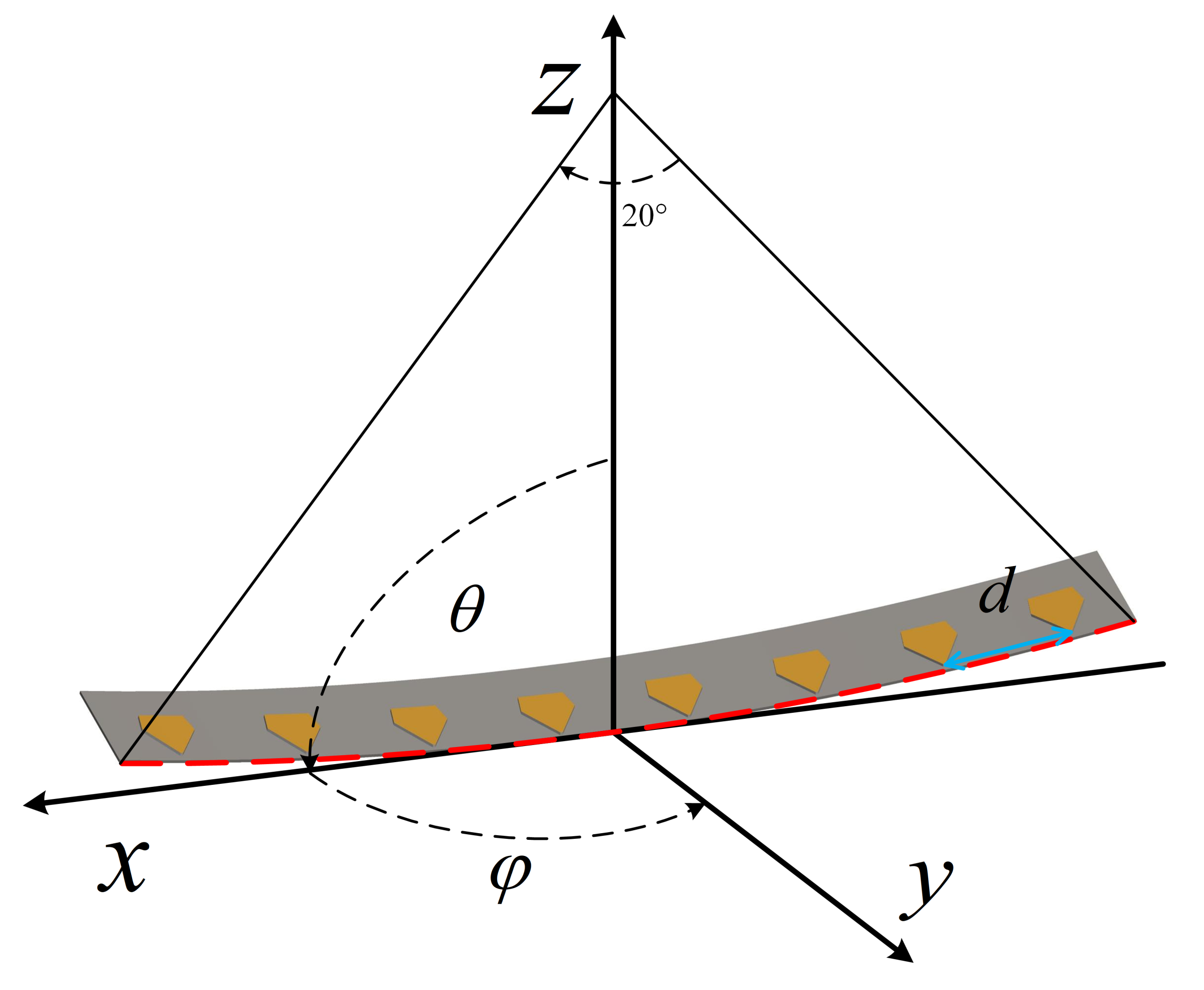
To demonstrate the effectiveness of the proposed PSO-based method for realistic beamforming problems, a curved array is considered for beam steering. Full-wave electromagnetic (EM) simulations require a long running time to determine the optimized weights, as each iteration of the full-wave simulation requires computationally expensive calculation with the whole array structure. However, with the proposed algorithm, the optimized weights can be efficiently computed by employing the known radiation pattern of each element, which can be extracted from full-wave simulations with each element being excited independently. The structure of the curved array used is illustrated in Figure 14.
The purpose of this example is to demonstrate the multiobjective beamforming capability of the proposed method. This example demands manipulating the positions of desired main beams in addition to maintaining the sidelobes at low levels. The requirement for beams synthesized from the curved array is stringent, which includes 60 degrees of scanning capability from the broadside with a sidelobe level 20 dB lower than the main lobe. It is challenging to achieve this goal using the analytical method where the phase shift for each array element is calculated by their relative locations with respect to the scan angle, which is particularly difficult when a curved array is considered. Excitation amplitude and phase associated with each array element must be optimized to achieve this goal. Therefore, the modified PSO is used for the beam pattern optimization, and the results are accordingly validated through EM simulations.
As shown in Figure 15, before implementing the proposed algorithm for coefficient determination, the steering vectors were derived directly from (1) while a uniform amplitude was assumed, resulting in a beam pattern with a peak SLL of −8.26 dB with the main lobe direction at 54 . After implementing the proposed method for pattern synthesis, the peak SLL acquired was as low as −13.95 dB with the main beam pointing at 53 . The obtained weights from the algorithm were then used to control the excitation signals for the array elements in the EM simulation. The beam pattern obtained through the EM simulation has a peak SLL of −12.9 dB and the main lobe direction of 52 . 25 . The good agreement between the result based on the algorithm and that of the full-wave simulation for verification indicated the robustness of the algorithm where multiple objectives of the beam pattern can be achieved without requiring complex EM calculation for each set of parameters during the optimizing process.
The excitation amplitude and phase obtained using different methods are shown in the Table 7. The acquisition time for optimal array coefficients can be significantly reduced by adopting the proposed method. In the full-wave simulations, the time to have the beam pattern produced with a planar array is approximately 5 min, and it tripled when the array is on the curved surface. It takes hundreds of simulations to seek the coefficients for a simple objective. However, it took only few minutes by the modified PSO algorithm once the embedded elements patterns were known. Additionally, it can incorporate more comprehensive requirements on the beam patterns without a marked increase for computation resources and time.
Table 8 provides a comprehensive overview of algorithms for synthesizing beam patterns for antenna arrays. These optimization technologies have specific application scenarios, and each technology has its own advantages and limitations. The algorithm proposed in this work can be improved by taking into account the mutual coupling effect between antennas in the arrays, and the proposed algorithm still needs to be tested for various antenna array configurations.

6. Conclusions

The particle swarm optimization algorithm is utilized for synthesizing array beams with multiple objectives, including multiple main lobes and several nulls in the radiation pattern. Based on scrutinizing classic PSO in the beamforming application, a modified PSO is proposed where the initial positions of particles are chosen based on the Taylor distribution instead of being randomly assigned. In addition, the fitness function incorporating multiple objectives is established. The combination of the new particle initialization and introduction of the new convergence condition enables the modified PSO to calculate beamforming weights for arrays with a large number of elements. The effectiveness of the proposed method is demonstrated with simulations and numerical results on four different scenarios, and its performance is compared with that of the classical PSO. The studied scenarios confirmed that the proposed algorithm is more efficient than the classical PSO in reaching convergence. It is potentially advantageous for solving beamforming problems with multiple objectives and sophisticated beamforming requirements. Finally, the proposed algorithm has also been used to optimize the directional pattern of a curved antenna array, and the results have verified the ability of the proposed algorithm to solve practical beamforming problems.

Author Contributions

Conceptualization, Y.Z. and C.M.; methodology, C.M.; software, C.M.; validation, C.M.; formal analysis, C.M.; investigation, C.M.; writing—original draft preparation, C.M.; writing—review and editing, C.M., Y.Z., M.T. and A.E.-M. All authors have read and agreed to the published version of the manuscript.

Funding

This work was supported in part by the National Natural Science Foundation of China under Grants 62174091 and 62201294, in part by Post-Doc International Exchange Programme YJ20210098.

Institutional Review Board Statement

Not applicable.

Informed Consent Statement

Not applicable.

Data Availability Statement

No new data were created or analyzed in this study. Data sharing is not applicable to this article.

Conflicts of Interest

The authors declare no conflicts of interest.

References

  1. Liang, S.; Fang, Z.; Sun, G.; Liu, Y.; Qu, G.; Zhang, Y. Sidelobe Reductions of Antenna Arrays via an Improved Chicken Swarm Optimization Approach. IEEE Access 2020, 8, 37664–37683. [Google Scholar] [CrossRef]
  2. Rocca, P.; Oliveri, G.; Mailloux, R.J.; Massa, A. Unconventional Phased Array Architectures and Design Methodologies—A Review. Proc. IEEE 2016, 104, 544–560. [Google Scholar] [CrossRef]
  3. Hong, W.; Jiang, Z.; Yu, C.; Zhou, J.; Chen, P.; Yu, Z.; Zhang, H.; Yang, B.; Pang, X.; Jiang, M.; et al. Multibeam Antenna Technologies for 5G Wireless Communications. IEEE Trans. Antennas Propag. 2017, 65, 6231–6249. [Google Scholar] [CrossRef]
  4. Ahmed, I.; Khammari, H.; Shahid, A.; Musa, A.; Kim, K.S.; De Poorter, E.; Moerman, I. A Survey on Hybrid Beamforming Techniques in 5G: Architecture and System Model Perspectives. IEEE Commun. Surv. Tutor. 2018, 20, 3060–3097. [Google Scholar] [CrossRef]
  5. Temiz, M.; Alsusa, E.; Baidas, M.W. Optimized Precoders for Massive MIMO OFDM Dual Radar-Communication Systems. IEEE Trans. Commun. 2021, 69, 4781–4794. [Google Scholar] [CrossRef]
  6. Han, S.; I, C.l.; Xu, Z.; Rowell, C. Large-scale antenna systems with hybrid analog and digital beamforming for millimeter wave 5G. IEEE Commun. Mag. 2015, 53, 186–194. [Google Scholar] [CrossRef]
  7. Molisch, A.F.; Ratnam, V.V.; Han, S.; Li, Z.; Nguyen, S.L.H.; Li, L.; Haneda, K. Hybrid Beamforming for Massive MIMO: A Survey. IEEE Commun. Mag. 2017, 55, 134–141. [Google Scholar] [CrossRef]
  8. Temiz, M.; Alsusa, E.; Danoon, L.; Zhang, Y. On the Impact of Antenna Array Geometry on Indoor Wideband Massive MIMO Networks. IEEE Trans. Antennas Propag. 2021, 69, 406–416. [Google Scholar] [CrossRef]
  9. Sohrabi, F.; Yu, W. Hybrid Digital and Analog Beamforming Design for Large-Scale Antenna Arrays. IEEE J. Sel. Top. Sign. Proces. 2016, 10, 501–513. [Google Scholar] [CrossRef]
  10. Temiz, M.; Alsusa, E.; Baidas, M.W. A Dual-Function Massive MIMO Uplink OFDM Communication and Radar Architecture. IEEE Trans. Cogn. Commun. Netw. 2022, 8, 750–762. [Google Scholar] [CrossRef]
  11. Owoola, E.O.; Xia, K.; Wang, T.; Umar, A.; Akindele, R.G. Pattern Synthesis of Uniform and Sparse Linear Antenna Array Using Mayfly Algorithm. IEEE Access 2021, 9, 77954–77975. [Google Scholar] [CrossRef]
  12. Haupt, R. Phase-only adaptive nulling with a genetic algorithm. IEEE Trans. Antennas Propag. 1997, 45, 1009–1015. [Google Scholar] [CrossRef]
  13. Keizer, W.P.M.N. Amplitude-Only Low Sidelobe Synthesis for Large Thinned Circular Array Antennas. IEEE Trans. Antennas Propag. 2012, 60, 1157–1161. [Google Scholar] [CrossRef]
  14. Aslan, Y.; Puskely, J.; Roederer, A.; Yarovoy, A. Phase-Only Control of Peak Sidelobe Level and Pattern Nulls Using Iterative Phase Perturbations. IEEE Antennas Wirel. Propag. Lett. 2019, 18, 2081–2085. [Google Scholar] [CrossRef]
  15. Mahto, S.K.; Choubey, A. A Novel Hybrid IWO/WDO Algorithm for Interference Minimization of Uniformly Excited Linear Sparse Array by Position-Only Control. IEEE Antennas Wirel. Propag. Lett. 2016, 15, 250–254. [Google Scholar] [CrossRef]
  16. Guney, K.; Onay, M. Amplitude-only pattern nulling of linear antenna arrays with the use of bees algorithm. Prog. Electromagn. Res.-Pier 2007, 70, 21–36. [Google Scholar] [CrossRef]
  17. Ni, G.; Song, Y.; Chen, J.; He, C.; Jin, R. Single-Channel LCMV-Based Adaptive Beamforming With Time-Modulated Array. IEEE Antennas Wirel. Propag. Lett. 2020, 19, 1881–1885. [Google Scholar] [CrossRef]
  18. Capon, J. High-resolution frequency-wavenumber spectrum analysis. Proc. IEEE 1969, 57, 1408–1418. [Google Scholar] [CrossRef]
  19. Zardi, F.; Nayeri, P.; Rocca, P.; Haupt, R. Artificial intelligence for adaptive and reconfigurable antenna arrays: A review. IEEE Antennas Propag. Mag. 2020, 63, 28–38. [Google Scholar] [CrossRef]
  20. Chen, K.; He, Z.; Han, C. A modified real GA for the sparse linear array synthesis with multiple constraints. IEEE Trans. Antennas Propag. 2006, 54, 2169–2173. [Google Scholar] [CrossRef]
  21. Jin, N.; Rahmat-Samii, Y. Advances in particle swarm optimization for antenna designs: Real-number, binary, single-objective and multiobjective implementations. IEEE Trans. Antennas Propag. 2007, 55, 556–567. [Google Scholar] [CrossRef]
  22. Khodier, M.M.; Christodoulou, C.G. Linear array geometry synthesis with minimum sidelobe level and null control using particle swarm optimization. IEEE Trans. Antennas Propag. 2005, 53, 2674–2679. [Google Scholar] [CrossRef]
  23. Chatterjee, S.; Chatterjee, S.; Poddar, D.R. Synthesis of linear array using Taylor distribution and Particle Swarm Optimisation. Int. J. Electron. 2015, 102, 514–528. [Google Scholar] [CrossRef]
  24. Rajo-Iglesias, E.; Quevedo-Teruel, O. Linear array synthesis using an ant-colony-optimization-based algorithm. IEEE Antennas Propag. Mag. 2007, 49, 70–79. [Google Scholar] [CrossRef]
  25. Saxena, P.; Kothari, A. Optimal pattern synthesis of linear antenna array using grey wolf optimization algorithm. Int. J. Antennas Propag. 2016, 2016, 1205970. [Google Scholar] [CrossRef]
  26. Zhang, C.; Fu, X.; Ligthart, L.P.; Peng, S.; Xie, M. Synthesis of broadside linear aperiodic arrays with sidelobe suppression and null steering using whale optimization algorithm. IEEE Antennas Wirel. Propag. Lett. 2018, 17, 347–350. [Google Scholar] [CrossRef]
  27. Hassan, R.; Cohanim, B.; De Weck, O.; Venter, G. A comparison of particle swarm optimization and the genetic algorithm. In Proceedings of the 46th AIAA/ASME/ASCE/AHS/ASC Structures, Structural Dynamics and Materials Conference, Austin, TX, USA, 18–21 April 2005; p. 1897. [Google Scholar]
  28. Ludwig Barbosa, V.; Schlosser, E.; Machado, R.; Heckler, M.V.T. Beamforming of a linear array applying pso algorithm with restrictive approach. J. Commun. Inf. Syst. 2016, 31, 118–126. [Google Scholar]
  29. Chang, J.C. A robust adaptive array beamformer using particle swarm optimization for space–time code division multiple access systems. Inf. Sci. 2014, 278, 174–186. [Google Scholar] [CrossRef]
  30. Azhiri, F.A.; Tazehkand, B.M.; Abdolee, R. PSO-based optimal beamforming in MmWave-NOMA systems with sparse antenna array. Soft Comput. 2022, 26, 10513–10526. [Google Scholar] [CrossRef]
  31. Van Trees, H.L. Optimum Array Processing: Part IV of Detection, Estimation, and Modulation Theory; John Wiley & Sons: Hoboken, NJ, USA, 2002. [Google Scholar]
  32. Eberhart, R.; Kennedy, J. A new optimizer using particle swarm theory. In Proceedings of the MHS’95. Proceedings of the Sixth International Symposium on Micro Machine and Human Science, Nagoya, Japan, 4–6 October 1995; pp. 39–43. [Google Scholar] [CrossRef]
  33. Shi, Y.; Eberhart, R. A modified particle swarm optimizer. In Proceedings of the 1998 IEEE International Conference on Evolutionary Computation Proceedings: IEEE World Congress on Computational Intelligence (Cat. No. 98TH8360), Anchorage, AK, USA, 4–9 May 1998; pp. 69–73. [Google Scholar] [CrossRef]
  34. Eberhart; Shi, Y. Particle swarm optimization: Developments, applications and resources. In Proceedings of the 2001 Congress on Evolutionary Computation (IEEE Cat. No. 01TH8546), Seoul, Republic of Korea, 27–30 May 2001; Volume 1, pp. 81–86. [Google Scholar] [CrossRef]
  35. Clerc, M.; Kennedy, J. The particle swarm-explosion, stability, and convergence in a multidimensional complex space. IEEE Trans. Evol. Comput. 2002, 6, 58–73. [Google Scholar] [CrossRef]
  36. Piotrowski, A.P.; Napiorkowski, J.J.; Piotrowska, A.E. Population size in particle swarm optimization. Swarm Evol. Comput. 2020, 58, 100718. [Google Scholar] [CrossRef]
  37. Marini, F.; Walczak, B. Particle swarm optimization (PSO). A tutorial. Chemom. Intell. Lab. Syst. 2015, 149, 153–165. [Google Scholar] [CrossRef]
  38. Engelbrecht, A. Particle swarm optimization: Velocity initialization. In Proceedings of the 2012 IEEE Congress on Evolutionary Computation, Brisbane, Australia, 10–15 June 2012; pp. 1–8. [Google Scholar] [CrossRef]
  39. Eberhart, R.; Shi, Y. Comparing inertia weights and constriction factors in particle swarm optimization. In Proceedings of the 2000 Congress on Evolutionary Computation, CEC00 (Cat. No.00TH8512), La Jolla, CA, USA, 16–19 July 2000; Volume 1, pp. 84–88. [Google Scholar] [CrossRef]
  40. Cazzaniga, P.; Nobile, M.S.; Besozzi, D. Prediction of high-throughput protein-protein interactions based on protein sequence information. In Proceedings of the 2015 IEEE Conference on Computational Intelligence in Bioinformatics and Computational Biology (CIBCB), Niagara Falls, ON, Canada, 12–15 August 2015. [Google Scholar]
  41. Taylor, T.T. Design of line-source antennas for narrow beamwidth and low side lobes. IRE Trans. Antennas Propag. 1955, 3, 16–28. [Google Scholar] [CrossRef]
  42. Goudos, S.K.; Moysiadou, V.; Samaras, T.; Siakavara, K.; Sahalos, J.N. Application of a Comprehensive Learning Particle Swarm Optimizer to Unequally Spaced Linear Array Synthesis With Sidelobe Level Suppression and Null Control. IEEE Antennas Wirel. Propag. Lett. 2010, 9, 125–129. [Google Scholar] [CrossRef]
  43. Sun, G.; Liu, Y.; Chen, Z.; Liang, S.; Wang, A.; Zhang, Y. Radiation Beam Pattern Synthesis of Concentric Circular Antenna Arrays Using Hybrid Approach Based on Cuckoo Search. IEEE Trans. Antennas Propag. 2018, 66, 4563–4576. [Google Scholar] [CrossRef]
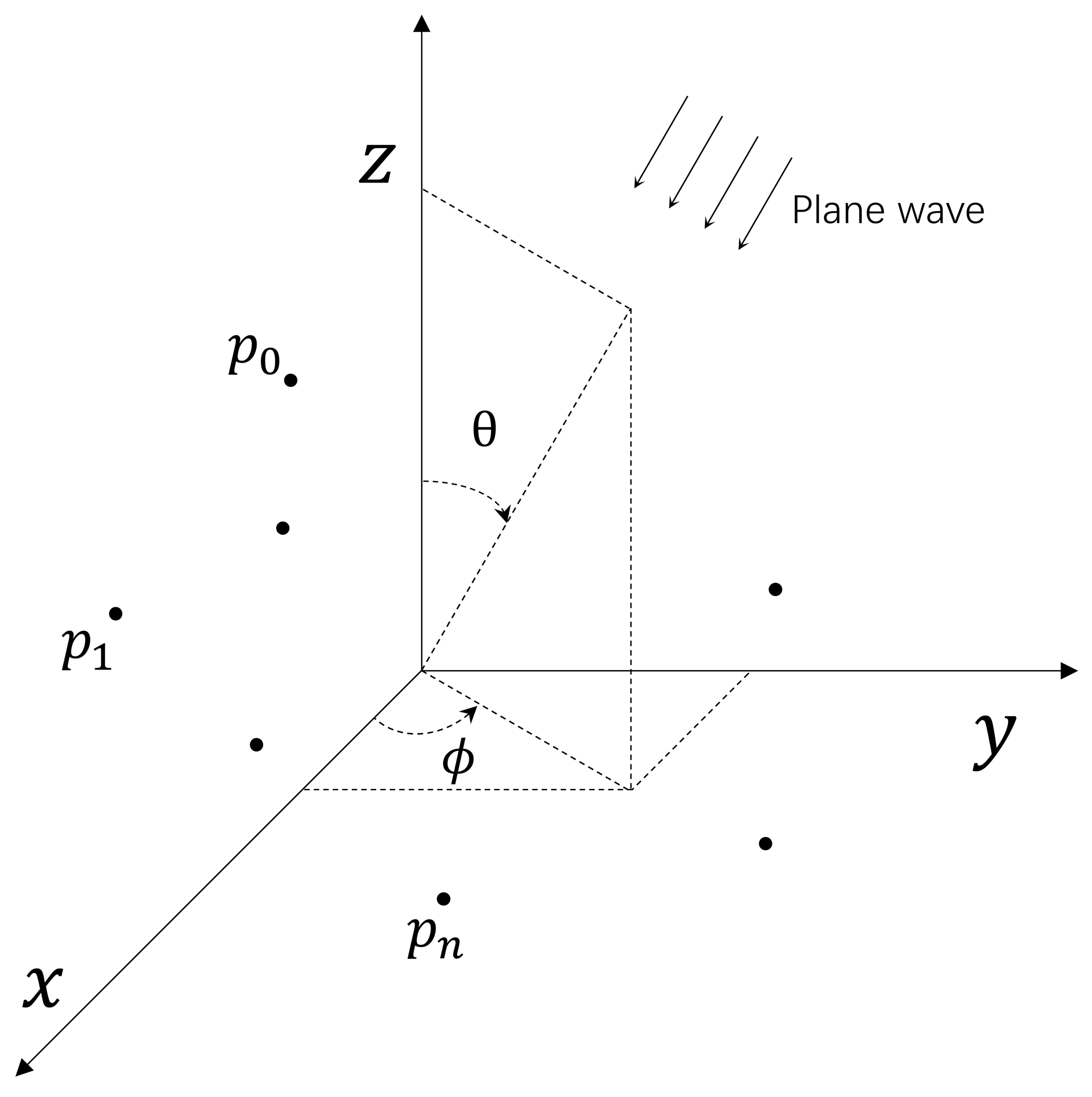
Figure 1. Antenna array with an impinging plane wave.
Electronics 13 00752 g001
Figure 2. Linear array along z-axis.
Electronics 13 00752 g002
Figure 3. The given initial values representing particles’ positions adopting two initialization strategies, with a particle population of 10 and a particle dimension of 8 (which is also the number of antenna elements). (a) Initialize particles using the uniform random distribution, (b) On the basis of Taylor Weights, a small random value was added on top to each each position to initialize the particles.
Electronics 13 00752 g003
Figure 4. The convergence comparison of the PSO method adopting three different initialization strategies, the conventional uniform distribution, following Chebyshev and Taylor distribution.
Electronics 13 00752 g004
Figure 5. Impact of the indicator of the Taylor distribution on the PSO algorithm, convergence performance of the improved PSO algorithm was analyzed with various values given to the indicator, n.
Electronics 13 00752 g005
Figure 6. The flowchart of the proposed PSO.
Electronics 13 00752 g006
Figure 7. The synthesized pattern with a null at θ = 150 and the required low SLL, 20 dB lower than the main lobe.
Electronics 13 00752 g007
Figure 8. The synthesized pattern with a null at θ = 101 and the required SLL, 20 dB lower than the main lobe.
Electronics 13 00752 g008
Figure 9. The optimized array beam pattern with eight nulls and the peak SLL less than −20 dB.
Electronics 13 00752 g009
Figure 10. The synthesized beam pattern with a broad null in the angular range between 120 and 130 and the required SLL, 20 dB lower than the main lobe.
Electronics 13 00752 g010
Figure 11. The synthesized array radiation pattern with 2 beams, 3 nulls, and the required SLL with the modified PSO.
Electronics 13 00752 g011
Figure 12. The achieved radiation pattern for an array with 100 elements, the multiobjective for optimization including 13 main lobes and 12 nulls being obtained simultaneously.
Electronics 13 00752 g012
Figure 13. The convergence profile comparison between the implementations using the Classic PSO algorithm and the Modified PSO algorithm in four design scenarios, where the two algorithms were carried out ten times and the fitness values were averaged for each scenario.
Electronics 13 00752 g013
Figure 14. The finite array of 8 elements is curved from a linear array into an arch shape spanning 20 , and the linear array before bending had a uniform inter-element spacing of a half wavelength at 1 GHz, d = 0.15 m. The array element is a patch antenna fed with the coplanar waveguide.
Electronics 13 00752 g014
Figure 15. The beam pattern of the curved array was synthesized through analytic determination, the improved PSO, and full-wave simulation for verification. The beam pattern of the full-wave simulation was based on the weights from the improved PSO algorithm, the target direction of the main lobe is in the plane of φ = 0 and the scan angle is θ = 60 .
Electronics 13 00752 g015
Table 1. Definition of the scenarios and objectives.
ScenarioArray ElementsNull Number or TypeMain Lobe NumberDNDLDSLL
11611−70 dB−20 dB
21681−60 dB−20 dB
316range1−50 dB−20 dB
41632−60 dB−20 dB
51001213−50 dB−20 dB
Table 2. The depths of obtained nulls.
Angle
(Degree)
Depth
(dB)
Angle
(Degree)
Depth
(dB)
25−63.24110−60.03
40−60.26125−61.42
55−60.91140−60.43
70−60.05155−61.01
Table 3. The null depths of the synthesized beam.
Angle
(Degree)
Depth
(dB)
Angle
(Degree)
Depth
(dB)
Angle
(Degree)
Depth
(dB)
23−50.0972−50.49120−50.35
36−49.9884−50.04132−50.94
48−58.0796−53.02144−50.00
60−55.53108−52.61157−49.99
Table 4. The parameter settings, average execution time, and final average fitness values obtained after ten repeated operations using two algorithms on each scenario.
Scenario Pop _ size Average Fitness ValueAverage Execution Time (s)
Classic PSOModified PSOClassic PSOModified PSO
11002.089067.973.97
22002.7290.093129.8385.28
31003.2390.02764.9739.12
41002.0090.01646.8233.89
Table 5. The weights of each element optimized by the classical and modified PSO in four designed scenarios.
Scenario 1Scenario 2Scenario 3Scenario 4
Modified PSOClassic PSOModified PSOClassic PSOModified PSOClassic PSOModified PSOClassic PSO
E10.64 + j0.600.57 + j0.680.26 + j0.370.16 + j0.010.29 + j0.420.35 + j0.350.26 + j0.150.39 + j0.98
E20.41 + j0.230.35 + j0.590.31 + j0.260.25 + j0.190.43 + j0.010.27 + j0.450.12 + j0.320.63 + j0.51
E30.61 + j0.360.48 + j0.390.38 + j0.310.43 + j0.470.43 + j0.460.76 + j0.360.11 + j0.120.32 + j0.96
E40.69 + j0.580.61 + j0.490.59 + j0.630.53 + j0.490.45 + j0.540.27 + j0.510.35 + j0.490.79 + j0.96
E50.61 + j0.590.59 + j0.630.63 + j0.620.38 + j0.510.80 + j0.770.75 + j0.580.48 + j0.700.92 + j0.79
E60.79 + j0.730.36 + j0.920.78 + j0.770.66 + j0.740.91 + j0.840.84 + j0.700.82 + j0.801.00 + j0.77
E70.79 + j0.820.54 + j0.640.83 + j0.880.80 + j0.790.87 + j0.720.78 + j0.720.90 + j0.661.00 + j0.51
E80.74 + j0.870.45 + j0.630.70 + j0.730.60 + j0.680.96 + j0.860.72 + j0.720.75 + j0.870.74 + j1.00
E90.77 + j0.840.68 + j0.890.71 + j0.750.53 + j0.650.86 + j0.810.61 + j0.870.84 + j0.890.90 + j0.83
E100.84 + j0.800.75 + j0.630.84 + j0.890.67 + j0.640.86 + j0.800.72 + j0.550.76 + j0.740.79 + j0.00
E110.76 + j0.730.37 + j0.860.77 + j0.750.73 + j0.670.84 + j0.870.62 + j0.460.45 + j0.860.80 + j0.91
E120.69 + j0.710.67 + j0.730.60 + j0.590.72 + j0.680.71 + j0.730.58 + j0.520.65 + j0.680.77 + j1.00
E130.55 + j0.470.49 + j0.360.59 + j0.690.58 + j0.480.43 + j0.720.68 + j0.430.71 + j0.370.58 + j0.29
E140.57 + j0.430.39 + j0.560.40 + j0.420.33 + j0.290.49 + j0.630.36 + j0.410.58 + j0.010.75 + j0.00
E150.39 + j0.400.12 + j0.270.30 + j0.330.41 + j0.370.04 + j0.490.48 + j0.410.26 + j0.370.51 + j0.76
E160.87 + j0.630.56 + j0.540.24 + j0.340.40 + j0.180.35 + j0.350.21 + j0.000.21 + j0.210.31 + j0.05
Table 6. The FNBW and HPBW of the beam patterns generated under various SLLs and nulls requirements.
Element NumberFNBW (Degree)HPBW (Degree)Target SLL (dB)Target Null Angle (Degree)Obtained SLL (dB)Obtained NDL (dB)
1615.16.4−15135−15.02−64.25
1615.86.6−1585−15.21−68.45
1615.56.8−1520−15.67−67.02
1618.17.2−20135−20.03−68.66
1617.37.1−2085−20.07−72.50
1617.57.1−2020−21.00−65.05
1619.97.7−25135−25.19−64.25
1619.67.6−2585−25.02−62.37
1620.27.7−2520−25.21−60.01
Table 7. The comparison of the excitation schemes on the finite array between the direct analytic determination with a Taylor tapering and the Modified PSO.
E1E2E3E4E5E6E7E8
AnalyticAmplitude0.760.851.111.271.271.110.850.76
DeterminationPhase (rad)8.946.463.891.25−1.47−4.26−7.12−10.03
Modified PSOAmplitude0.630.690.750.750.680.600.420.42
Phase (rad)8.986.464.021.34−1.36−3.81−6.80−9.87
Table 8. Comparison of optimization techniques of synthesizing beam patterns.
Ref.AlgorithmDesignFunctionPerformance
 [25]GWOUniform linear array.Optimal antenna positions and amplitudes for achieving minimum SLL along with null placement and suppression of the first side lobe.Lower SLL was obtained; however, GWO is more computationally time-consuming than PSO.
[26]WOALinear aperiodic array.WOA was applied to the synthesis of uniformly excited broadside linear aperiodic arrays with sidelobe suppression and null steering under constraints on beamwidth requirements.The average fitness result of WOA is slightly higher than that of CLPSO [42]. WOA has fewer iterations than CLPASO [42] and higher iterations than IWO-WDO [15].
[11]Mayfly Algorithm (MA)Uniform and sparse linear array.MA was applied for sidelobe suppression and null placement in the following two ways: by optimizing amplitudes while maintaining uniform spacing and by optimizing the antenna positions while assuming a uniform amplitude excitation.MA is able to obtain a considerable improvement in peak SLL suppression and null control. However, MA requires a longer computation time and more parameters than PSO.
[15]Hybrid invasive weed optimization and wind-driven optimization (IWO/WDO)Linear sparse array.The proposed algorithm is implemented to synthesize the uniformly excited linear sparse array pattern having an SLL and null control with a constraint on beamwidth by optimizing the element position only.The Hybrid algorithm has improved performance in terms of null control, beamwidth control, and the rate of convergence. The proposed algorithm requires fewer iterations for convergence compared to PSO.
[43]Cuckoo Search (CS)Large scale concentric circular antenna array (CCAA).A hybrid approach to suppress the SLL of large-scale CCAA is proposed, which includes an improved discrete cuckoo search algorithm (IDCSA) for thinning the CCAA and a cuckoo search-invasive weed algorithm (CSIWA) for further optimizing the thinned CCAA.The proposed IDCSA and CSIWA can obtain a lower maximum SLL but do not have advantages in terms of processing time.
This workModified PSOUniform linear array.A modified PSO algorithm is proposed for optimizing multiple objectives in radiation pattern, including SLL, null, and main lobe direction, by optimizing the excitation phase and amplitude of the elements.The proposed algorithm has shown good performance compared to classical PSO in multiple design scenarios, and its effectiveness was verified with a curved array.
Disclaimer/Publisher’s Note: The statements, opinions and data contained in all publications are solely those of the individual author(s) and contributor(s) and not of MDPI and/or the editor(s). MDPI and/or the editor(s) disclaim responsibility for any injury to people or property resulting from any ideas, methods, instructions or products referred to in the content.