
Beampattern Synthesis and Optimization Method Based on Circular Frequency Diverse Array Engineering Model

1
College of Information Engineering, Inner Mongolia University of Technology, Hohhot 010051, China
2
Inner Mongolia Key Laboratory of Radar Technology and Application, Hohhot 010051, China
*
Author to whom correspondence should be addressed.
Electronics 2024, 13(9), 1618; https://doi.org/10.3390/electronics13091618
Submission received: 11 March 2024
/
Revised: 21 April 2024
/
Accepted: 23 April 2024
/
Published: 24 April 2024
(This article belongs to the Special Issue Applications of Array Antenna in Modern Wireless Systems)
Abstract
:The frequency diverse array (FDA) is capable of generating range-angle-dependent beampatterns by introducing a tiny frequency offset to the transmit carrier frequency of each array element. However, the beam-scanning potential of conventional linear FDA applications is limited, notably in their incapacity for 360° omnidirectional scanning. This paper introduces a method that leverages the geometric configuration of circular frequency diverse arrays (CFDAs) for synthesizing and optimizing beampatterns through a practical engineering approach. Initially, we compute the structural parameters and configurations of CFDA. Subsequently, the isophase plane is utilized to adjust the phase of each array element. Ultimately, the CFDA structure is used to optimize the non-uniform frequency offset, and the beampattern, which is capable of 360° omnidirectional scanning, is realized by low sidelobe optimization. Simulation results affirm that the CFDA antenna, as per the actual engineering model, possesses precise dot-shaped beampattern scanning abilities across both range and angle dimensions.
1. Introduction
The concept of the frequency diverse array (FDA) was initially proposed in 2006 [1]. The FDA and Phased Array (PA) both transmit coherent signals, but the FDA introduces a frequency offset to the transmitted signals that is significantly smaller than the carrier frequency. The FDA typically generates an S-shaped beampattern, which is characterized by an array factor that is a function of three variables: angle, range, and time. This innovation has introduced a new dimension to antenna array design, attracting significant attention since its inception [2,3,4]. Research has demonstrated that the FDA and PA possess similar physical properties. When the frequency offset of the FDA is reduced to zero, it effectively becomes equivalent to a PA, as reported in [5].
The transmit beampattern of the FDA antenna exhibits unique characteristics due to its dependence on frequency, time, and spatial range. This dependency introduces issues such as range–angle domain coupling and time-varying beampatterns, which are fundamental considerations in FDA design and application. Employing symmetric logarithmic frequency offsets serves as a conventional strategy to mitigate the problems posed by beampattern coupling, as explained by [6]. This approach leverages the variation of frequency offsets to facilitate control over the beampattern’s directionality and focus. Further exactitude in FDA design is achieved through the implementation of non-uniform frequency offsets derived from both random in [7] and structured approaches, such as subarray configurations in [8]. These strategies enable the synthesis of highly focusable dot-shaped beampatterns [9]. In addition, advanced techniques for target localization and sidelobe suppression have been developed, including the application of Taylor window weighting in [10], discrete Fourier transform in [11], and an array of intelligent algorithms in [12,13,14]. These methodologies collectively contribute to the refinement of the FDA’s capabilities, optimizing its performance for complex radar and communication tasks. The time-varying aspect of transmitted FDA beampatterns poses additional problems. Recent literature [15] critically reevaluates the conventional understanding of time-varying FDAs, scrutinizing the mathematical formulations from [16,17,18] and clarifying misconceptions that have persisted in the field. This comprehensive analysis sheds light on the time-varying characteristics of FDA systems, encompassing conventional FDAs, time-modulated weighted FDAs, and transmit–receive FDAs [19]. The outcomes offer new perspectives on optimizing FDA designs to achieve dynamic, adaptable beampatterns suitable for an array of applications ranging from sophisticated radar surveillance to advanced communication systems.
In recent years, numerous studies have explored methods to integrate FDAs with other established technologies. For instance, the integration of FDA technology with Multiple-Input Multiple-Output (MIMO) systems represents a leap forward in radar technology [20,21,22,23,24]. FDA-MIMO systems leverage the inherent advantages of both technologies to achieve superior target detection and resolution capabilities. By utilizing non-uniform frequency offsets, FDA-MIMO systems can generate focusable dot-shaped beampatterns, enabling the precise targeting and identification of objects in cluttered environments. The combination enhances clutter suppression and improves the ability to distinguish between closely spaced targets, which is a critical factor in both military and civilian radar applications. Additionally, the fusion of FDAs with cognitive radar technology introduces adaptive capabilities to radar systems [25]. Cognitive FDA radar systems can dynamically adjust frequency offsets in response to environmental conditions, maximizing the radar’s effectiveness in varying scenarios. This adaptability ensures optimal performance, significantly improving the signal-to-interference-plus-noise ratio (SINR) and direction-of-arrival (DOA) estimation accuracy compared to conventional FDA systems. The integration with cognitive technologies underscores the FDA’s potential in intelligent radar systems, particularly in applications requiring high levels of environmental awareness and adaptability.
However, the aforementioned studies on FDAs are all predicated upon research conducted with conventional linear arrays. Conventional linear arrays generate high sidelobes, potentially diminishing anti-interference capabilities and resulting in false alarms or misjudgments. Furthermore, beam scanning with conventional arrays faces angular limitations, potentially creating blind zones that ineffectively detect targets or interference sources. Under extreme angular conditions, antenna gain is reduced, and the main lobe beam broadens, adversely affecting target monitoring. In scenarios that necessitate omni-directional antenna scanning, it is essential to have narrower main lobe beams and reduced levels of secondary lobes for achieving higher precision and minimizing interference [26]. To address these limitations, circular array configurations have been introduced [27,28,29]. Although the literature [30,31] proposes a circular FDA, it fundamentally constitutes a planar array rather than a genuine ring array. The literature [32] presents an array structure combining the FDA with a circular array, which is envisioned as an idealized ring-shaped configuration. Given the circular array’s manufacturing complexity, we proposed a polygonal array, constituted by multiple linear arrays, to approximate a circular array and facilitate wide-beam scanning. This configuration allows for selective array element activation, precise phase compensation, and employs a unique symmetric logarithmic frequency offset, enabling 360° omnidirectional beam scanning to adeptly handle diverse targets and environmental conditions. Additionally, this study does not account for mutual and self-coupling nor does it address application-specific challenges like noise effects, non-ideal radiators, complex targets, and phase noise.
The rest of the paper is organized as follows: Section 2 outlines the structure of the CFDA and delves into its approximation model; Section 3 details the synthesis and optimization methods for beampatterns with non-uniform frequency offsets; and Section 4 conducts simulation verification. Finally, Section 5 offers conclusions.
2. Proposed Structure Model
The CFDA is adept at accomplishing 360° omni-directional scanning, yet the attainment of perfect circularity presents challenges during the machining and manufacturing processes. This section endeavors to streamline the structural design and establish a theoretical analytical model of significant reference value.
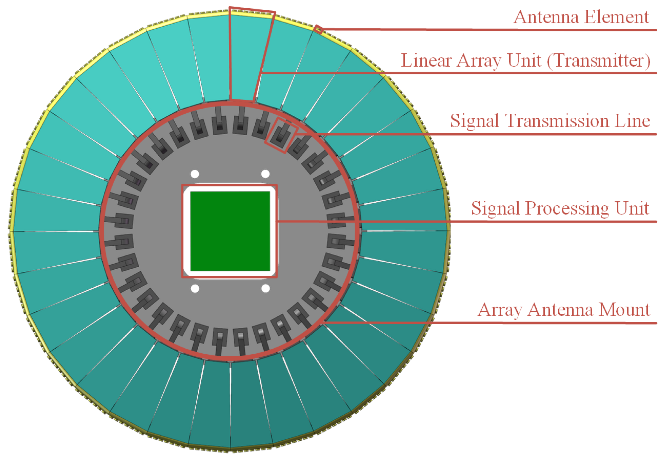
Our approach utilizes a polygonal array as an approximation of the circular array. As shown in Figure 1, this study designs a conventional linear array in a head-to-tail configuration to approximate a circular array. It is accurate within the framework of this research to describe this circular formation as effectively an inner regular polygon, which serves as an approximation of an ideal circle. Each side of the polygonal array is identified as a linear array unit with the aggregate number of these units represented by . For enhanced clarity in analyzing the CFDA structure, the model from Figure 1 is simplified in Figure 2. We designate the due-north direction as the baseline, assigning the array element in this direction the index 0. The numbering of subsequent elements proceeds in a clockwise direction, concluding with . In an ideal circular array where each array element’s distance from the center is R (denoting the radius of the array), the distance from each element to the center in the polygonal array configuration is designated as . It should be noted that in the following description, the polygonal arrays are uniformly referred to as circular arrays.
The theoretical analytical model of the circular array is depicted in Figure 2. Assuming the monitored target’s azimuth is precisely located at , represents the angle between the target direction and the north reference azimuth, and denotes the angle of activated arrays. Here, “target direction” is defined as the line from the center of the sub-array to the target. signifies the angle occupied by each array unit within the circular array, and represents the angular separation between two adjacent array elements, which is an approximation. To achieve a focusable beampattern on the monitored target, a suitable array element must be selected for activation. Initially, the determination of the reference array element index, represented by , is based on the target’s angle information and is calculated as follows:
where represents the rounding operation, is the number of circular array antenna array elements, and is the number of array elements contained in one linear array unit.
Upon determining the -th reference array element, the centered arrays elements within the aperture angle can be activated. Each operational array element, centered around the -th element, is symmetrically positioned on both sides. The aperture angle can be expressed as shown below:
where , denoting the number of activated array elements within the aperture angle , is required to be an odd number to facilitate the symmetry of the beampattern, as defined by and illustrated in Figure 3. During the 360° omnidirectional scanning, beam steering is accomplished by sequentially activating adjacent linear array units with the occupied array angle being and including elements. For specific scenarios, we can design the activated aperture angle and the number of activated array elements according to the needs.
The distance of array element from the array center point can be expressed as shown below:
with
In the computational process, serves a crucial role by facilitating the calculation of . Specifically, it denotes the position of each array element within the respective linear array units. As shown in Figure 3, the projection of the distance between the m-th activated array element and the reference array element on the vertical axis can be expressed as shown below:
The projection of the distance between the m-th activated array element and the reference array element on the horizontal axis can be expressed as shown below:
3. Beampattern Synthesis
The beampattern synthesis of a CFDA antenna is based on the synthesis of the beampattern in the isophase plane. A significant challenge in the beam scanning of a CFDA antenna is that each array element occupies a distinct position and exhibits a unique aperture orientation. This implies that conventional methods for linear arrays are not directly applicable to CFDAs. As a result, each selected working array element is considered to be positioned on the isophase plane through a projection method following the transformation of the circular structure into its corresponding shape. This enables the calculation of beam scanning of the CFDA in the desired direction by leveraging the theoretical foundations and research methodologies pertinent to linear arrays. Therefore, this section provides a brief overview of the beampattern synthesis for a conventional linear FDA while offering a comprehensive exploration of a CFDA.
3.1. Conventional Linear FDA Radar
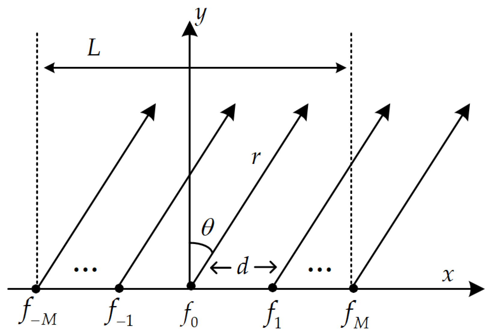
Conventional linear FDA radars are shown in Figure 4 by attaching a frequency offset to the transmitted signal on adjacent array elements. The radiated frequency of the 0-th array element is , while the radiated signal frequency of the m-th array element is shown below:
In order to solve the coupling problem of the beampattern in the range–angle domain, the symmetric logarithm [6] is used here as the frequency offset of the conventional linear array, which can be expressed as
where M is the number of array elements. Assuming that the desired beampattern pointing angle is and the pointing range is , the expression for the array factor corresponding to the conventional uniform linear FDA [2,3,4,5] can be obtained as shown below:
3.2. Proposed CFDA Radar
It is assumed that the target position is known to be . To generate a dot-shaped beampattern with lower sidelobes at the designated target location, this paper proposes a synthesis and optimization method for the beampattern based on the CFDA engineering model, as illustrated in Figure 5. Initially, the reference array element index is determined based on the angle information of the target. Subsequently, array elements within the aperture angle are activated. Next, phase compensation is applied to establish an isophase plane. Finally, beampattern synthesis and optimization are completed.
3.2.1. Phase Compensation
Beam scanning in a circular array can be analogously analyzed as that of a linear array with non-uniform spacing between elements on the isophase plane. The antenna beam’s angle domain scanning occurs to both the left and right of the normal direction of the equivalent linear array. The schematic of beam scanning, based on the equivalent linear array, is depicted in Figure 6. Phase compensation on the isophase plane, determined by the projection of the distance between the m-th activated array element and the reference array element in the vertical axis, is expressed as shown below:
where is the carrier frequency.
3.2.2. Beampattern Synthesis
As shown in Figure 7, assuming that the expected target satisfies the far-field approximation condition at any position, then when the target is located at point P, according to the basic principle of the FDA antenna, the signal transmitted by the m-th array element can be expressed as shown below:
where denotes the complex weight of the m-th array element and T denotes the transmitted pulse duration.
The carrier frequency is . Using of the reference array element as the reference point, set . The frequency of the transmitted signal of the m-th array element is designed as shown below:
where is the frequency offset of the m-th array element.
The distance from the m-th array element to the target point should be
where r is the distance from the target, and is the direction of the target, .
Then, the total signal at the far-field expectation target P is
The array factor can be expressed as
In order for the target under monitoring to have a single peak at the desired range and azimuth , the complex weight can be calculated as:
The beampattern of the desired target can be written as follows:
3.3. Beampatterns Optimization
Sidelobe performance significantly influences the tactical and technical parameters of radar systems. The 3 dB mainlobe bandwidth and the peak sidelobe level are crucial performance metrics that decisively impact the system’s clutter interference resistance capabilities. Thus, it is imperative to minimize sidelobe power, optimizing radar system parameters while preserving the power of the target signal. This optimization begins with the adjustment of the array elements’ radiated frequencies, which is followed by amplitude weighting. For this purpose, two window functions, the Hamming window and the Taylor window, are employed, both of which are suited for CFDA applications.
3.3.1. Frequency Offset Optimization
The CFDA is designed as a circular configuration, encircled by linear array units arranged head-to-tail, with uniformly distributed spacing between the array elements of each unit. This uniform distribution undergoes modifications when the activated array elements are projected onto the isophase plane due to the CFDA’s inherent curved architecture, which results in alterations in the spacing of array elements on this plane. To mitigate this issue, we refine the approach to optimizing the symmetric logarithmic frequency offset. This refinement involves the introduction of a frequency offset distribution coefficient, enhancing the precision of the frequency offset adjustment. The formulation of this coefficient is as follows:
As the index number of the array element increases, the frequency offset distribution coefficient exhibits a valley-shaped pattern corresponding to the inverse density weighting observed in the spacing of array elements.
To address the coupling issue within the beampattern in both the range and angle domains, we adjust the symmetric logarithmic frequency offset to accommodate the unique structure of the CFDA. The frequency offset of the m-th array element can be formulated as shown below:
where is the frequency offset constant.
3.3.2. Sidelobe Suppression
Taylor and Hamming window functions are both used in radar beamforming for amplitude weighting, optimizing performance by adjusting beam shape, yet they have distinct characteristics and applications.The Taylor window is adept at precisely controlling sidelobe levels without altering the main lobe width, which is ideal for applications that demand stringent sidelobe suppression. Its main advantage lies in its customizability of sidelobe attenuation, but it requires complex design and may compromise resolution. The Hamming window, on the other hand, is simpler and focuses on reducing sidelobe amplitudes, inevitably widening the main lobe slightly. It is best suited for cases where sidelobe reduction is crucial but a slight increase in the main lobe width is acceptable. The advantage of the Hamming window is its simplicity and effectiveness in sidelobe suppression with the trade-off being a minor loss in resolution due to a wider main lobe.
The Hamming window, suitable for the CFDA, can be expressed as shown below:
The Taylor window suitable for the CFDA can be expressed as shown below:
The specified sidelobe level can be achieved by adjusting the parameters and . In the calculation , .
4. Comparative Analysis of Simulation Results
The CFDA in this paper is actually approximated by a polygonal array structure, and in beampattern synthesis, the beam scan of the CFDA can be analyzed equivalently to the case of a line array with unequally spaced array elements on an isophase. Therefore, this section firstly gives a comparison of the array element spacing between the linear FDA and the CFDA at the isophase. Since the array element spacing has changed, we analyze it for the beampattern characteristics. In addition, in the array antenna, the sidelobe level fundamentally reflects the ability of the space array antenna to suppress interference signal sources. Therefore, this section also conducts simulation analysis on the optimization method of the CFDA.
4.1. Analysis of Simulation Results before Optimization
In order to validate the proposed CFDA, beampattern simulation verifications are carried out, and the simulation parameters are shown in Table 1.
Owing to the unique arc-shaped structure of the CFDA, as the elements are projected onto the isophase plane, their equivalent element spacing becomes non-uniformly distributed. The density of the equivalent spacing is primarily determined by the radius R of the array, the angular interval between adjacent elements, and the aperture angle of the activated elements, as depicted in Equations (3) and (6). To elucidate its variation characteristics more clearly, with the same number of activated elements and array length L, a linear array featuring uniformly distributed element spacing is introduced for comparative analysis, whose structure is depicted in Figure 3 and Figure 4. When the element spacing in the linear array equals half a wavelength, the equivalent spacing in the CFDA is illustrated in Figure 8. The element spacing in the linear FDA is uniform, whereas the CFDA’s arc-shaped structure impacts its element spacing, leading to a distribution where spacing is sparser in the center and denser at the edges on the isophase plane—a contrast to the density-weighted optimization method, which is known as the inverse density weighting phenomenon. It is important to note that in calculating the CFDA’s dimensions, L represents the projected length on the isophase plane rather than the actual length. Consequently, given that the total length L remains constant and the number of activated elements remain unchanged, the principal distinction between the linear FDA and CFDA lies in their element spacing.
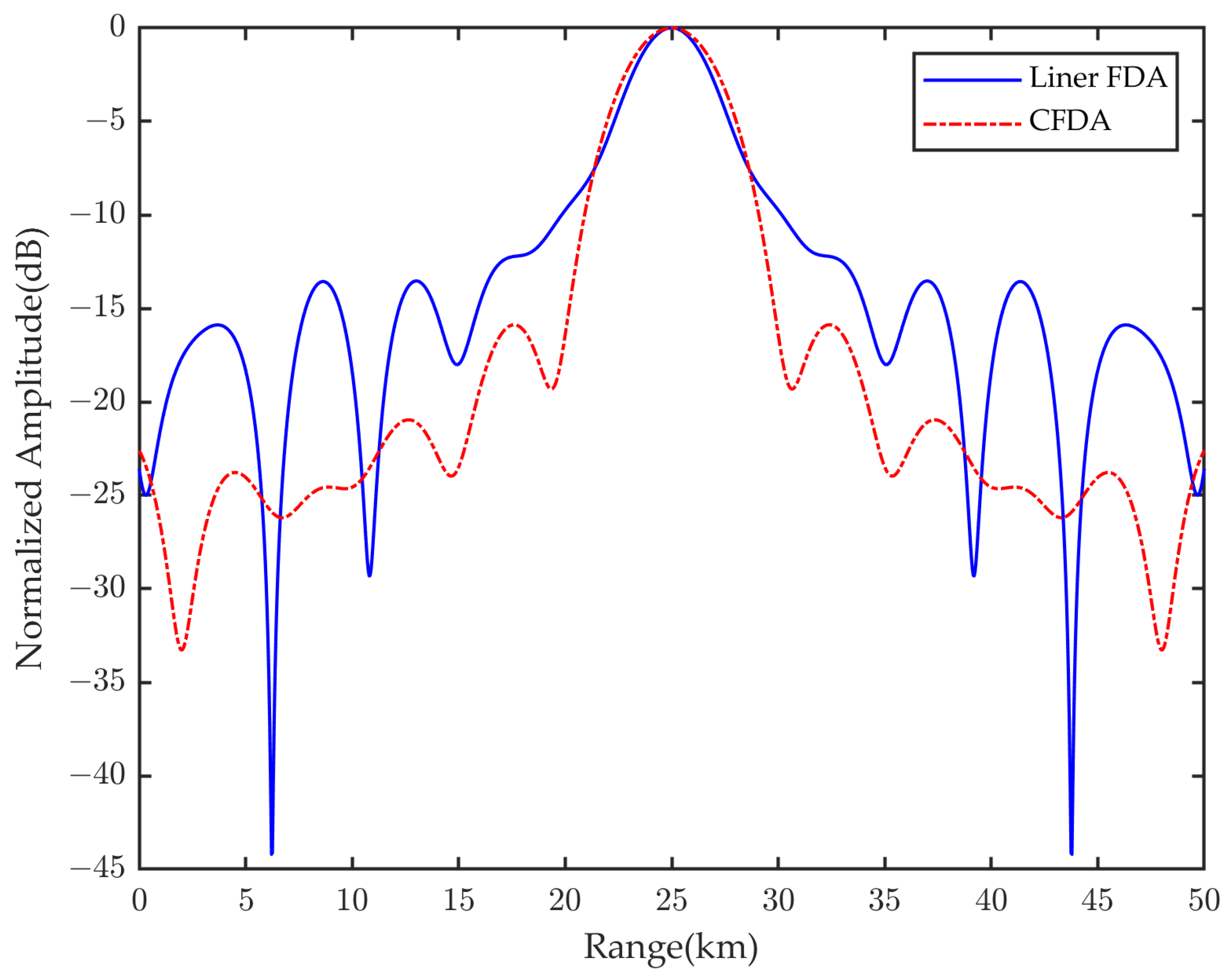
For the conventional linear FDA, we calculated its array factor using Equation (9). For the CFDA, its array factor was determined based on Equation (17). The frequency offset delineated in Equation (8) was applied to both arrays with simulation-based verification conducted for each. The outcomes of these simulations are shown in Figure 9. These results illustrate that under identical conditions, with the sole difference being the structure of the arrays, the CFDA’s beampattern amplitude in the angle domain shows an increase of approximately 1 dB compared to the conventional linear FDA. Meanwhile, in the range domain, the beampattern amplitude increase is significantly less than 1 dB, which is considered negligible. Consequently, the CFDA offers the advantage of 360° omnidirectional scanning albeit at the expense of a minor elevation in the sidelobe levels within the angle domain.
4.2. Analysis of Simulation Results after Optimization
In optimizing the beampattern of a linear FDA, employing density weighting of the element spacing can lower the sidelobe level without compromising transmission power. However, the arc-shaped structure of the CFDA leads to an inverse density weighting of its element spacing. To counteract the impact of this inverse density weighting, we optimized the frequency offset of the CFDA by introducing a frequency distribution coefficient . We applied the frequency offsets detailed in Equations (8) and (19) to separately simulate the beampattern of the CFDA, and the outcomes are shown in Figure 10. These results demonstrate that the optimized frequency offset exerts a robust suppression effect on the sidelobes within the range domain.
Upon optimizing the frequency offsets, we implemented amplitude weighting on the CFDA with the findings shown in Figure 11. It becomes evident that amplitude weighting, utilizing both the Hamming window and the Taylor window, effectively suppresses sidelobes in the CFDA’s beampattern optimization process. The dot-shaped beampattern that results from this optimization clearly exhibits a substantial reduction in the first-order sidelobe. This reduction signifies the transfer of the first-order sidelobe’s energy from the vicinity of the main lobe to areas farther from the main lobe, thereby significantly enhancing the system’s anti-interference capability.
Further analysis of the amplitude weighting’s impact on sidelobe level suppression is presented in Figure 12, which provides the beampattern’s contour curves in both range and angle domains. For comparative analysis, a conventional linear array is also included in the illustration. In Figure 12a, the amplitude-weighted optimization is shown to slightly widen the main lobe beamwidth at the expense of significantly reducing the first-order sidelobe in the range domain and markedly improving interference suppression and focus. Figure 12b reveals that amplitude weighting with the Hamming window notably reduces the sidelobe and slightly expands the main lobe. In comparison, Taylor window amplitude weighting results in lesser sidelobe reduction and less widening of the main lobe. The amplitude-weighted optimization of the CFDA, employing both Hamming and Taylor windows, significantly boosts sidelobe suppression over the unoptimized CFDA. Moreover, compared to the conventional linear FDA, the CFDA not only achieves 360° omnidirectional scanning but also significantly lowers its sidelobe level in both range and angle domains. This leads to an improved focusable dot-shaped beampattern, enhancing the overall system performance.
5. Conclusions
In this paper, we propose a theoretical and analytical framework for CFDAs, detailing the system parameters and criteria for selecting array elements within the model. Given the unique curved architecture of CFDAs, a novel beam synthesis approach predicated on the isophase plane concept is developed. This methodology allows for the beam formation at the isophase plane through phase adjustment of the individual active array elements. However, a problem identified in this process is the inverse density weighting phenomenon, which affects the spacing of the array element projections on the isophase plane. To mitigate this issue, we have innovatively designed a non-uniform frequency offset strategy. This strategy significantly diminishes the sidelobe levels in the range domain by finely tuning the frequency offsets. Furthermore, beam optimization is achieved through amplitude weighting, effectively minimizing sidelobe interference on the target detection. This approach notably enhances spot beam performance, particularly in terms of peak sidelobe ratio, thereby boosting the precision and resolution of radar antenna measurements. The CFDA represents a novel structural evolution within FDA technology, overcoming the constraints of conventional linear FDA designs. It achieves 360° omnidirectional beam scanning, offering fresh perspectives for advancements in radar, communications, and targeted monitoring in specific real-world applications. Simulation outcomes substantiate the practicality and efficacy of the proposed method.
Author Contributions
Conceptualization, W.X.; methodology, W.X.; software, W.X. and C.P.; validation, W.X. and P.H.; formal analysis, C.P.; investigation, W.X. and C.P.; resources, W.X. and W.T.; data curation, C.P.; writing—original draft preparation, W.X. and C.P.; writing—review and editing, W.X. and P.H.; visualization, P.H.; supervision, W.T. and Z.G.; project administration, W.T. and P.H.; funding acquisition, P.H. and W.X. All authors have read and agreed to the published version of the manuscript.
Funding
This research was funded by the National Natural Science Foundation of China under Grant Number 62071258 and in part by the Key Project of Regional Innovation and Development Joint Fund of National Natural Science Foundation under Grant Number U22A2010.
Data Availability Statement
Data are contained within the article.
Conflicts of Interest
The authors declare no conflicts of interest.
References
- Antonik, P.; Wicks, M.C.; Griffiths, H.D.; Baker, C.J. Frequency diverse array radars. In Proceedings of the 2006 IEEE Conference on Radar, Verona, NY, USA, 24–27 April 2006; pp. 215–217. [Google Scholar] [CrossRef]
- Xu, J.W.; Zhu, S.Q.; Liao, G.H.; Zhang, Y.H. An overview of Frequency Diverse Array radar technology. J. Radars 2018, 7, 167–182. [Google Scholar] [CrossRef]
- Wang, W.Q. Overview of frequency diverse array in radar and navigation applications. IET Radar Sonar Navig. 2016, 10, 1001–1012. [Google Scholar] [CrossRef]
- Wang, W.Q.; Chen, H.; Zheng, Z.; Zhang, S.S. Advances on frequency diverse array radar and its applications. J. Radars 2018, 7, 153–166. [Google Scholar] [CrossRef]
- Wang, W.Q.; Shao, H.Z.; Chen, H. Frequency diverse array radar: Concept, principle and application. J. Electron. Inf. Technol. 2016, 38, 1000–1011. [Google Scholar] [CrossRef]
- Khan, W.; Qureshi, I.M.; Saeed, S. Frequency diverse array radar with logarithmically increasing frequency offset. IEEE Antennas Wirel. Propag. Lett. 2014, 14, 499–502. [Google Scholar] [CrossRef]
- Liu, Y.M.; Ruan, H.; Wang, L.; Nehorai, A. The random frequency diverse array: A new antenna structure for uncoupled direction-range indication in active sensing. IEEE J. Sel. Top. Signal Process. 2016, 11, 295–308. [Google Scholar] [CrossRef]
- Wang, W.Q. Subarray-based frequency diverse array radar for target range-angle estimation. IEEE Trans. Aerosp. Electron. Syst. 2014, 50, 3057–3067. [Google Scholar] [CrossRef]
- Shao, H.Z.; Dai, J.; Xiong, J.; Chen, H.; Wang, W.Q. Dot-shaped range-angle beampattern synthesis for frequency diverse array. IEEE Antennas Wirel. Propag. Lett. 2016, 15, 1703–1706. [Google Scholar] [CrossRef]
- Liao, Y.; Tang, H.; Chen, X.L.; Wang, W.Q. Frequency diverse array beampattern synthesis with Taylor windowed frequency offsets. IEEE Antennas Wirel. Propag. Lett. 2020, 19, 1901–1905. [Google Scholar] [CrossRef]
- Zubair, M.; Ahmed, S.; Alouini, M.S. Frequency diverse array radar: New results and discrete Fourier transform based beampattern. IEEE Trans. Signal Process. 2020, 68, 2670–2681. [Google Scholar] [CrossRef]
- Xiong, J.; Wang, W.Q.; Shao, H.Z.; Chen, H. Frequency diverse array transmit beampattern optimization with genetic algorithm. IEEE Antennas Wirel. Propag. Lett. 2016, 16, 469–472. [Google Scholar] [CrossRef]
- Lan, L.; Liao, G.S.; Xu, J.W.; Wen, J. Range-angle pencil-beamforming for non-uniformly distributed array radar. Multidimens. Syst. Signal Process. 2018, 29, 867–886. [Google Scholar] [CrossRef]
- Wang, W.Q.; Dai, M.M.; Zheng, Z. FDA radar ambiguity function characteristics analysis and optimization. IEEE Trans. Aerosp. Electron. Syst. 2017, 54, 1368–1380. [Google Scholar] [CrossRef]
- Chen, K.; Yang, S.W.; Chen, Y.k.; Qu, S.W. Accurate Models of Time-Invariant Beampatterns for Frequency Diverse Arrays. IEEE Trans. Antennas Propag. 2019, 67, 3022–3029. [Google Scholar] [CrossRef]
- Xu, Y.H.; Shi, X.W.; Xu, J.W.; Li, P. Range-angle-dependent beamforming of pulsed frequency diverse array. IEEE Trans. Antennas Propag. 2015, 63, 3262–3267. [Google Scholar] [CrossRef]
- Khan, W.; Qureshi, I.M. Frequency Diverse Array Radar With Time-Dependent Frequency Offset. IEEE Antennas Wirel. Propag. Lett. 2014, 13, 758–761. [Google Scholar] [CrossRef]
- Yao, A.M.; Wu, W.; Fang, D.G. Frequency Diverse Array Antenna Using Time-Modulated Optimized Frequency Offset to Obtain Time-Invariant Spatial Fine Focusing Beampattern. IEEE Trans. Antennas Propag. 2016, 64, 4434–4446. [Google Scholar] [CrossRef]
- Liao, Y.; Zeng, G.H.; Luo, Z.B.; Liu, Q.H. Time-Variance Analysis for Frequency-Diverse Array Beampatterns. IEEE Trans. Antennas Propag. 2023, 71, 6558–6567. [Google Scholar] [CrossRef]
- Zhang, Y.; Zhang, W. A method of mainlobe deception jamming countermeasure in FDA-MIMO radar. Radar Sci. Technol. 2017, 15, 671–676. [Google Scholar] [CrossRef]
- Zhang, Z.J.; Xie, J.W.; Li, X.; Sheng, C.; Hu, Q.Y. Discrimination method of range deception jamming based on FDA-MIMO. J. Beijing Univ. Aeronaut. Astronaut. 2017, 43, 738–746. [Google Scholar] [CrossRef]
- Li, Z.H.; Zhang, Y.S.; Ge, Q.C.; Xue, B. A robust deceptive jamming suppression method based on covariance matrix reconstruction with frequency diverse array MIMO radar. In Proceedings of the 2017 IEEE International Conference on Signal Processing, Communications and Computing (ICSPCC), Xiamen, China, 22–25 October 2017; pp. 1–5. [Google Scholar] [CrossRef]
- Lan, L.; Liao, G.; Xu, J.; Xu, Y.; So, H.C. Beampattern Synthesis Based on Novel Receive Delay Array for Mainlobe Interference Mitigation. IEEE Trans. Antennas Propag. 2023, 71, 4470–4485. [Google Scholar] [CrossRef]
- Zhang, Y.Q.; Liao, G.S.; Xu, J.W.; Zhang, X.P.; Lan, L. A Method to Suppress Interferences Based on Secondary Compensation with QPC-FDA-MIMO Radar. Remote Sens. 2023, 15, 4711. [Google Scholar] [CrossRef]
- Wang, W.Q. Cognitive frequency diverse array radar with situational awareness. IET Radar Sonar Navig. 2016, 10, 359–369. [Google Scholar] [CrossRef]
- Lan, L.; Liao, G.S.; Xu, J.W.; Zhang, Y.H.; Fioranelli, F. Suppression approach to main-beam deceptive jamming in FDA-MIMO radar using nonhomogeneous sample detection. IEEE Access 2018, 6, 34582–34597. [Google Scholar] [CrossRef]
- Fusco, V.F.; Chepala, A.; Abbasi, M.A.B. Target location using dual-beam directional modulated circular array. IEEE Trans. Antennas Propag. 2018, 66, 7525–7529. [Google Scholar] [CrossRef]
- Longhi, M.; Vellucci, S.; Barbuto, M.; Monti, A.; Zarghani, H. Array Synthesis of Circular Huygens Metasurfaces for Antenna Beam-Shaping. IEEE Antennas Wirel. Propag. Lett. 2023, 22, 2649–2653. [Google Scholar] [CrossRef]
- Khalaj-Amirhosseini, M.; Farhoudi, L. Synthesis of circular arrays with sidelobes of individually arbitrary levels. Int. J. Microw.-Comput.-Aided Eng. 2019, 29, e21752. [Google Scholar] [CrossRef]
- Wang, C.; Zhu, X. Three-dimensional parameter estimation of uniform circular frequency diverse array radar with two-stage estimator. IEEE Sens. J. 2021, 21, 17775–17784. [Google Scholar] [CrossRef]
- Ma, J.; Cai, J.; Zheng, Z.; Gao, X.; Huang, S. Spatiotemporal Evolution of Orbital Angular Momentum (OAM) Beams Based on a Uniform Circular Frequency Diverse Array (UC-FDA). IEEE Trans. Antennas Propag. 2023, 71, 4183–4193. [Google Scholar] [CrossRef]
- Xu, W.; Deng, Z.; Huang, P.; Tan, W.; Gao, Z. Beampattern synthesis and optimization for frequency diverse arc array based on the virtual element. Electronics 2023, 12, 2231. [Google Scholar] [CrossRef]
Figure 1.
Three-dimensional CFDA model.

Figure 2.
Two-dimensional CFDA geometric model.

Figure 3.
Parameter configuration of CFDA.

Figure 4.
Conventional linear FDA radar.

Figure 5.
Beampattern synthesis flow chart.

Figure 6.
Phase compensation.

Figure 7.
Beam scanning-based CFDA.

Figure 8.
The spacing of array elements projected at the isophase plane.

Figure 9.
Beampatterns synthesis results before optimization. (a) In the range domain. (b) In the angle domain.
Figure 9.
Beampatterns synthesis results before optimization. (a) In the range domain. (b) In the angle domain.

Figure 10.
Beampattern after frequency optimization.

Figure 11.
Beampatterns synthesis results. (a) CFDA beampattern. (b) In the range domain. (c) In the angle domain. (d) Hamming weighted. (e) Hamming weighted in the range domain. (f) Hamming weighted in the angle domain. (g) Taylor weighted. (h) Taylor weighted in the range domain. (i) Taylor weighted in the angle domain.

Figure 12.
Beampattern optimization result. (a) In the range domain. (b) In the angle domain.


Table 1.
Simulation parameters.
| Parameters | Symbol | Value |
|---|---|---|
| Carrier frequency | 10 Ghz | |
| Frequency offset | 10 Khz | |
| Number of linear array units | 29 | |
| Number of linear array elements | 5 | |
| Activated element number | 25 | |
| Aperture angle | ||
| Array radius | R | 0.36 m |
| Desired target range | 25 Km | |
| Desired target angle |
Disclaimer/Publisher’s Note: The statements, opinions and data contained in all publications are solely those of the individual author(s) and contributor(s) and not of MDPI and/or the editor(s). MDPI and/or the editor(s) disclaim responsibility for any injury to people or property resulting from any ideas, methods, instructions or products referred to in the content. |
© 2024 by the authors. Licensee MDPI, Basel, Switzerland. This article is an open access article distributed under the terms and conditions of the Creative Commons Attribution (CC BY) license (https://creativecommons.org/licenses/by/4.0/).
Share and Cite
MDPI and ACS Style
Xu, W.; Pei, C.; Huang, P.; Tan, W.; Gao, Z. Beampattern Synthesis and Optimization Method Based on Circular Frequency Diverse Array Engineering Model. Electronics 2024, 13, 1618. https://doi.org/10.3390/electronics13091618
AMA Style
Xu W, Pei C, Huang P, Tan W, Gao Z. Beampattern Synthesis and Optimization Method Based on Circular Frequency Diverse Array Engineering Model. Electronics. 2024; 13(9):1618. https://doi.org/10.3390/electronics13091618
Chicago/Turabian StyleXu, Wei, Changyu Pei, Pingping Huang, Weixian Tan, and Zhiqi Gao. 2024. "Beampattern Synthesis and Optimization Method Based on Circular Frequency Diverse Array Engineering Model" Electronics 13, no. 9: 1618. https://doi.org/10.3390/electronics13091618
Note that from the first issue of 2016, this journal uses article numbers instead of page numbers. See further details here.