Article

Application of a Centroid Frequency-Based Back Propagation Neural Network Fault Location Method for a Distribution Network Considering Renewable Energy Assessment

1
Power Dispatching and Control Center, Guangdong Power Grid Co., Ltd., Guangzhou 510600, China
2
Zhongshan Power Supply Bureau, Guangdong Power Grid Co., Ltd., Zhongshan 528400, China
3
School of Electrical Engineering, Chongqing University, Chongqing 400044, China
*
Author to whom correspondence should be addressed.
Electronics 2024, 13(8), 1491; https://doi.org/10.3390/electronics13081491
Submission received: 6 March 2024 / Revised: 8 April 2024 / Accepted: 9 April 2024 / Published: 14 April 2024

Abstract

:
The distribution network is a crucial component of the power system as it directly connects to users and serves the purpose of distributing power and balancing the load. With the integration of new energy sources through distributed generation (DG), the distribution network has undergone a transformation from a single power radial network into a complex multi-source network. Consequently, traditional fault location methods have proven inadequate in this new network structure. Therefore, the focus of this paper is to investigate fault location techniques specifically tailored for DG integration into distribution networks. This paper analyzes how fault conditions impact the characteristics of single-phase grounding faults and extracts spectral feature quantities to describe differences in zero-sequence currents under various fault distances. This paper also proposes a fault location method based on centroid frequency and a BPNN (back propagation neural network). The method uses centroid frequency to describe the features of zero-sequence currents; to simulate the mapping relationship between fault conditions and spectral features, BPNN is employed. The mapping relationship differs for different lines and distribution networks. When a line faults, the spectral features are calculated, along with the transition resistance and fault closing angle. The corresponding mapping relationship is then called upon to complete distance measurements. This location method can be applied to various types of distribution lines and fault conditions with high accuracy. Even with insufficient training samples, sample expansion can ensure accuracy in fault distance measurement. We built a distribution network consisting of four feeders with different types and lengths of each line on Simulink and verified the effectiveness of the proposed method by setting different fault conditions. The results suggest that the method has a clear advantage over other frequency domain-based approaches, especially for hybrid lines and feeder lines with branches in distribution networks. Additionally, the method achieves a measurement accuracy within a range of 100 m.

1. Introduction

Single-phase-to-earth faults account for 80% of fault events in distribution networks [1]. In addition, two-phase faults and three-phase faults are mostly developed from single-phase-to-earth faults. Fault location is meaningful for eliminating faults rapidly and raising the reliability of a power system. However, the medium voltage distribution network in China usually uses a neutral and ineffectively grounded system, whose currents and single-phase-to-earth faults are small. Therefore, fault line detection and fault location are difficult to undertake. Nowadays, many research papers are aimed at solving these problems. Unfortunately, as a result of complex grid structures and fault features, methods cannot handle some special situations such as high-resistance grounding, low fault closing angle grounding, and faults in hybrid lines or feeders with branches [2]. Although the fault features of steady states are not distinctive enough to detect, the transient zero-sequence currents contain much fault information. Common fault characteristics can be extracted by analyzing zero-sequence current frequency spectrums. Based on this, several methods for determining fault location have been proposed.

1.1. Background

In recent years, the depletion of traditional energy sources such as coal, oil, and natural gas, due to over-exploitation, has led to an increasingly severe energy crisis [3]. The large-scale development and utilization of these traditional energy sources has also caused significant pollution [4]. Given the high demand for electric energy across various industries, it is crucial to develop new energy sources to ensure power stability.
Renewable energy sources, like solar power, wind, and geothermal power, are widely available in nature and offer clean and pollution-free alternatives. Additionally, the emergence of distributed power generation, with distributed generator (DG) being extensively integrated into the distribution network, can help mitigate environmental pollution and reduce energy losses [5].
In China, the medium-voltage distribution network typically employs the method of neutral grounding without actual grounding, as described in References [6,7]. Instead, it utilizes grounding techniques, such as the arc-canceling coil or small resistance grounding. The presence of an arc-canceling coil helps compensate for the capacitive current, resulting in the resonant grounding system having the lowest fault current. Consequently, this poses a greater challenge when it comes to fault location in Reference [8].

1.2. Status of the Study

Currently, there are several methods used for determining the location of asymmetric faults in distribution networks [9]. These methods include the impedance method, traveling wave method, and the fault analysis method.
The impedance method in Reference [10] relied on the principle that the line impedance was proportional to the fault distance in a distribution network with a centralized parameter model. In a distribution network with a distributed parameter model, the line impedance and fault distance follow a hyperbolic tangent relationship. By establishing the relationship between voltage, current, line impedance, and fault distance, distance measurement can be achieved. The impedance method can also be extended to more complex distribution networks by establishing a node impedance matrix, but this involves more calculations. However, traditional impedance methods in Reference [11] did not account for the asymmetric operation state of the distribution network or the time-varying conditions of branch lines and loads. To address these limitations, Reference [12] proposed algorithms and equivalent methods for large distribution networks that considered branch lines and load. Reference [13] introduced a location method that utilized node impedance matrices and a load model with static voltage characteristics. It is important to note that the accuracy of the impedance method can be significantly affected by transition resistance. If the line impedance and load impedance cannot be accurately determined, the resulting location measurements may have significant deviations.
The traveling wave method cannot be affected by the distribution network operation mode and high impedance grounding easily. Recently, scholars have proposed fault location methods based on the traveling wave method, such as in References [14,15,16,17,18]. The traveling wave method is based on the time-frequency characteristic. The methods proposed in References [14,15,16,17,18] have to obtain the arrival time of the wave head and the speed; this is called the time-domain traveling wave method. This method solves the fault distance by measuring the arrival time difference of each wave head and establishing the equations about the fault distance, propagation time, and wave speed.
The key is to identify the nature of each wave head. Reference [14] gave the sources of the first three incoming wave heads for different fault distances. Reference [15] classified the traveling waves into four categories and analyzed them to obtain the categories of refracted waves to which the initial antipodal waves of the near-end fault and the far-end fault belong. Reference [16] was based on the arrival time differences between different frequency components of the traveling wave for location, using the wavelet transforms to carry out the time-frequency analysis. Reference [17] proposed a method to identify whether the second reverse traveling wave comes from the reflected wave at the fault point or the reflected wave at the opposite bus and combines with other wave heads to determine the location. Reference [18] used wavelet transform to decompose the traveling wave into signals of different frequency bands, extracted the frequency band in which the zero-mode reflected wave speed was closest to the initial wave speed, and determined the location by measuring the time difference between the arrival of the zero-mode and line-mode initial traveling waves and the time difference between the arrival of the two reflected waves. Due to the short distribution lines, the time differences between the wave heads were small, so a high sampling rate was needed. Coupled with the traveling wave “dispersion” effect, the wave speed is difficult to solve, and there are errors.
The methods proposed in References [19,20,21,22,23,24] do not require the identification of the traveling wave head, and their measurement time scales are large enough. Therefore, we classify this method as a failure analysis method. Among them, References [19,20] built transmission equations to identify the fault location, based on different frequency components of voltage and current, while References [21,22] identified the fault location based on the same frequency (IF) component of both the voltage and current. Reference [23] obtained the voltage expression of the fault point from both ends and acquired the fault distance based on the equality of the calculation results. Reference [24] completed the distance measurement by identifying the parameters of the zero-sequence full-wave equivalent circuit of the grounding potential of the arcing coil. In Reference [25], the distance measurement was accomplished by finding the intersection of the tangents of the voltage amplitude change curves at both ends of the line.
Existing fault analysis methods in References [14,15,16,17,18,19,20,21,22,23,24,25] cannot be applied to both hybrid lines and feeders with branches in distribution networks and have significant limitations. Distribution network fault characteristics are complex, and there are differences between various distribution network fault characteristics. The fault location method must be universal.

1.3. Algorithms for Fault Location

Artificial intelligence algorithms solve problems based on the laws of nature (biology) and the solution process is a simulation of a natural (biological) phenomenon [26].
Figure 1 shows the applications of an intelligent algorithm used in the power system. At present, artificial intelligence algorithms have been applied to many fields in the power system, and were helpful in improving the reliability of the power system and the economy of operation in Reference [27]. Many existing researchers have been devoted to fault location methods based on intelligent algorithms.
The genetic algorithm (GA) is renowned for its exceptional adaptability and robustness, rendering it a useful tool in various engineering domains. Within the context of distribution networks, an innovative fault location methodology grounded in GA principles was expounded upon in Reference [28]. Moreover, in Reference [29], a comprehensive evaluation function was formulated, augmenting the mathematical framework employed for fault location.

1.4. Main Work

Locating asymmetric faults for small current grounding systems in active distribution systems can be challenging, and existing methods may not be suitable for all types of distribution lines and special fault situations. In this chapter, we will investigate the influence of fault distance, fault closing angle, and transition resistance on the spectrum of zero-sequence current and develop a fault routing and location method based on spectral characteristics. This approach is more comprehensive, considering various fault conditions, and has both generality and practicality.
A fault location method based on centroid frequency and a BPNN (back propagation neural network) is proposed. The centroid frequency is used to describe the feature wherein low-frequency components of zero-sequence currents increase when the fault distance grows longer. The impact on centroid frequency of the fault distance, fault closing angle, and transition resistance is researched, and the relationship between centroid frequency and its factors is simulated by the BPNN. Furthermore, an assisted criterion is proposed, to confirm the fault location for a situation where the centroid frequency–fault distance curve is not monotone. The results prove that the method has an obvious advantage over other methods based on frequency domain features, in the terms of hybrid lines and lines with branches and can be applied to complex structures in distribution networks [30]. Accurate location results are realized when training samples lack data and contain errors.

2. Fault Characterization Analysis

In this chapter, we will investigate the relationship between fault conditions, network structure, and line parameters of a distribution network, and how they impact the waveform and spectrum of the zero-sequence current during asymmetrical faults [31].

2.1. Overview

2.1.1. Distributed Generator

Distributed generation (DG) typically refers to small, modular, and geographically compatible independent power sources that have a generation capacity location from a few kilowatts to fifty megawatts. These sources are connected to voltage levels of 35 kV and below. DG offers several benefits over traditional energy sources, including reducing environmental pollution and energy loss. In China, DG is widely utilized due to its small footprint and high flexibility. There are four main types of DG commonly used today, namely solar power, wind power, small hydro power, and fuel cell power.
Among these technologies, photovoltaic (PV) power generation stands out due to its wide distribution of resources, minimal geographical limitations, and low pollution. In the following section, we will provide a detailed description of the advantages associated with PV power generation.

2.1.2. Photovoltaic Power Generation

Grid-connected photovoltaic power generation systems are further divided into two types: centralized photovoltaic power generation systems and distributed photovoltaic power generation systems. A centralized photovoltaic power generation system is shown in Figure 2. In areas with abundant light energy resources, the electricity generated by photovoltaic power generation is directly connected to the power grid through transmission lines for load use. This method has low operating costs and is easy to expand, due to the abundant and centralized light energy resources, but the line losses are large, due to the need for long-distance transmission.
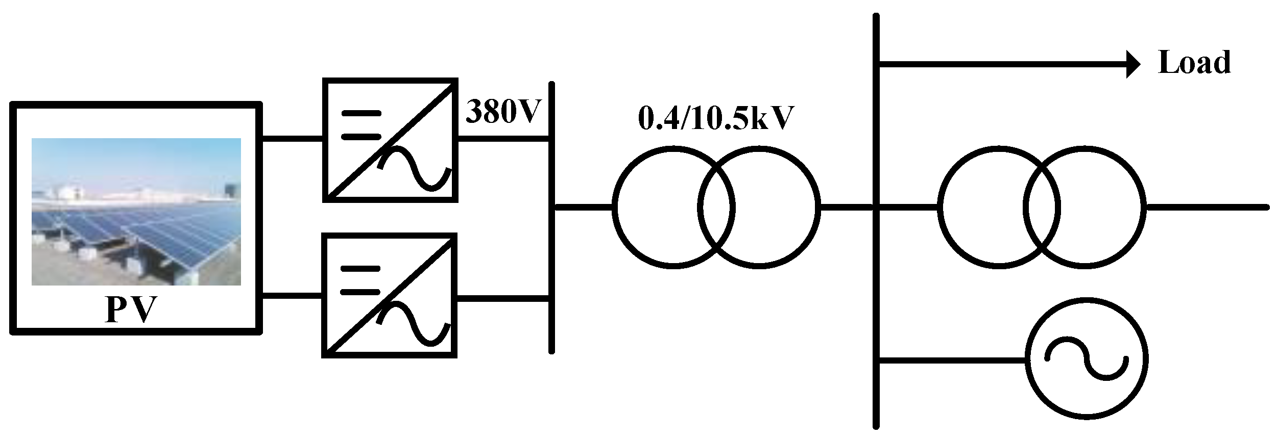
In distributed photovoltaic power generation grid-connected systems, as shown in Figure 3, the power generated by photovoltaic power generation is directly available for use by users, and the remaining part of the power can be distributed to the grid for use by other loads. This method is suitable for user-concentrated areas, because the PV power in the user side can reduce line losses and provide flexible operation, but PV grid-connected power generation leads to the failure of the traditional protection adjustment scheme and, therefore, a need for re-adjustment.

2.2. Analysis of Asymmetrical Fault

When the DG is connected, as illustrated in Figure 4, it will have an impact on the traditional relay protection device, making the distribution network structure more complex. The power direction will appear to be a bidirectional flow, the location of the DG access will have an impact on the size of the fault current as well as the phase, and the fault information uploaded by some of the FTUs (Feeder Terminal Units) will be incomplete, which leads to the inaccuracy of the traditional fault location method [32].
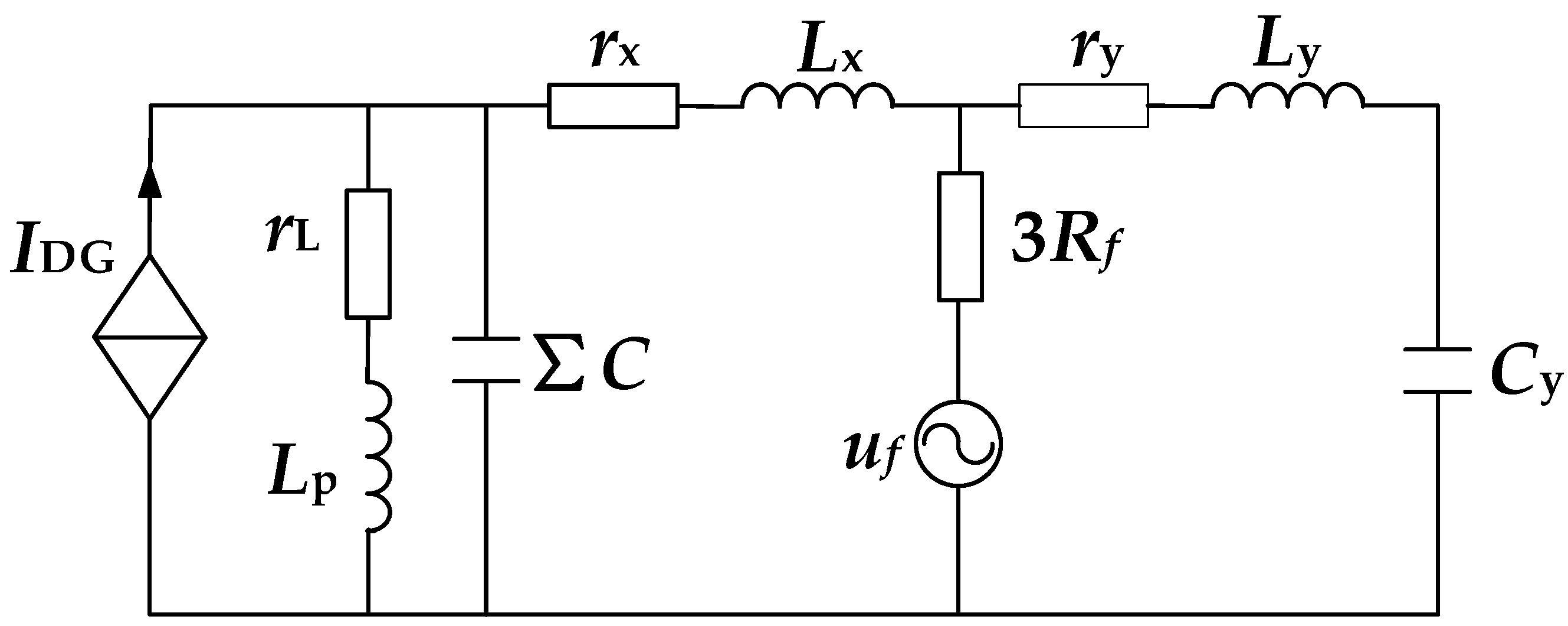
The single-phase grounded neutral equivalent circuit for the distribution network is established as depicted in Figure 5. Here, rx, Lx, ry, and Ly denote the resistance and inductance of the fault line upstream and downstream from the fault point, respectively. ΣC represents the equivalent capacitance of the upstream portion of the faulted line and all healthy lines. rL and Lp represent three times the grounding resistance and grounding inductance of the arc-extinguishing coil, while Rf denotes the transition resistance.
The analysis demonstrates that, in the case of an asymmetrical fault occurring in the system, identifying the fault distance, transition resistance, and fault closing angle facilitates the assessment of zero-sequence voltage and current spectrum during the fault. Consequently, fault location methodologies relying on transient characteristics must account for the effects of these three factors on fault localization. Through a comprehensive understanding of the impact of fault distance, transition resistance, and fault closure angle, the precise fault location can be attained.
Constant power mode: In this mode, when operating correctly, Pout = PREF and Qout = QREF (Pout and Qout represent the instantaneous output active power and reactive power of DG, respectively) [33]. To decouple P and Q, the d-axis is oriented to the PCC (Point of Common Coupling) voltage rotation vector (uP,q = 0, where uP,q is the q-axis component of instantaneous output active power). In this scenario, the DG current reference value is determined as follows:
i d , REF = 2 3 P REF u P , d i q , REF = 2 3 Q REF u P , d
Low-voltage ride-through mode: In this mode, when the PCC voltage drops abnormally, the DG outputs additional reactive current to provide voltage support. The DG current reference during low-voltage ride-through is determined under the premise of not exceeding the device overload capability, as shown in (2). Here, IDGR represents the rated current, u P * is the PCC voltage standard unit value, and K1, K2, and Kmax correspond to the voltage support factor, reactive current peak factor, and overload current multiple, respectively.
i q , REF = 0 u P * > 0.9 K 1 I DGR ( 0.9 u P * )   0.2   u P * 0.9 K 2 I DGR   u P * < 0.2 i d , REF = min 2 3 P REF u P , d , ( K max I DGR ) 2 i q , REF 2
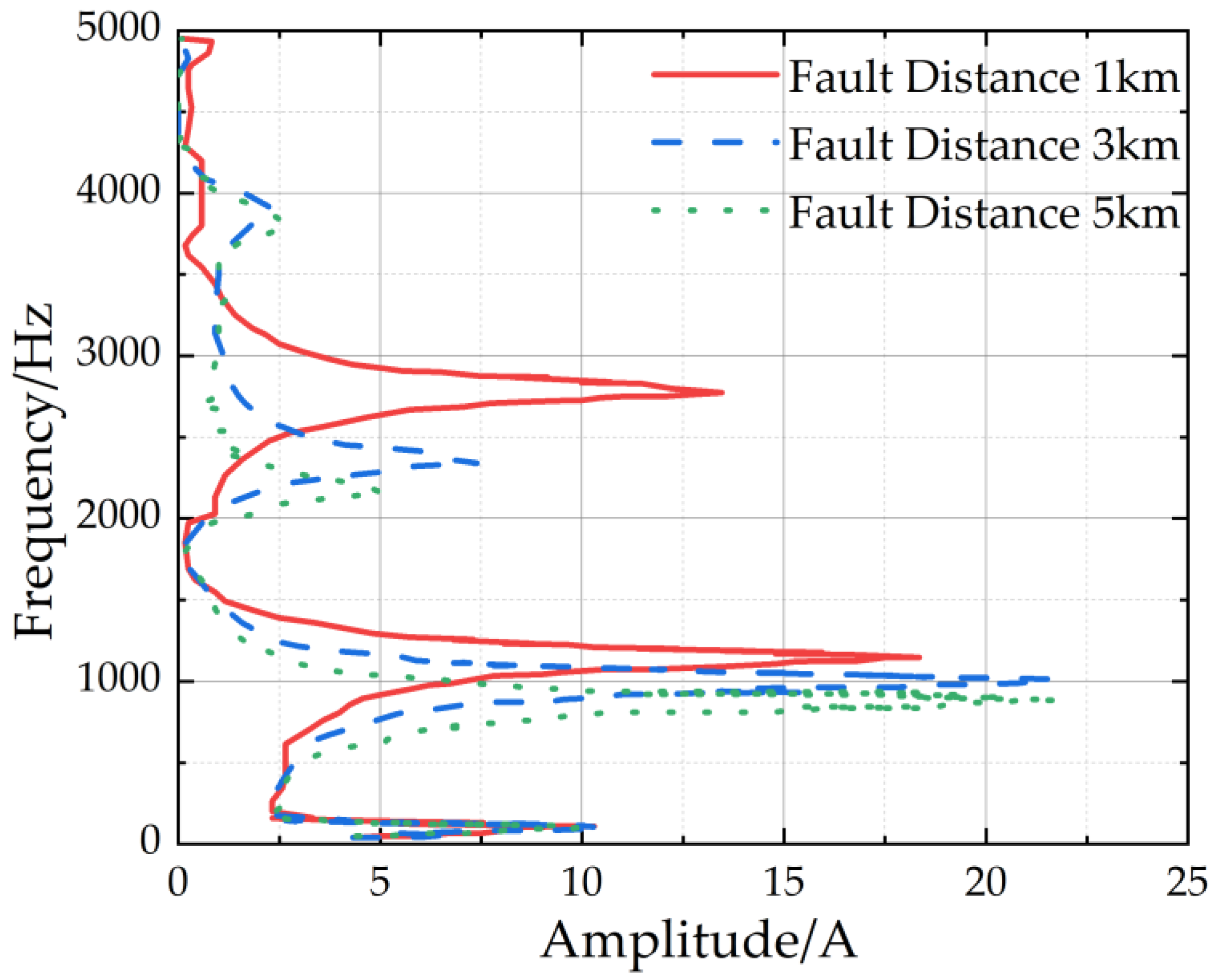
We constructed the model containing three cable lines in Simulink, each of which was 6 km long. The parameters were set as follows. The grounding inductance was set to 0.5463 H, and the grounding resistance is set to 5.149 Ω. The line unit length resistance, inductance, and capacitance were 0.102 Ω/km, 0.892 × 10⁻³ H/km, and 0.212 × 10⁻⁶ F/km, respectively. The closing angle was set to 90°, while the transition resistance was set to 1 Ω. The transient zero-sequence current spectrum at the end of line 3, for various fault distances, is depicted in Figure 6. It is evident that, with an increasing fault distance, the current spectrum progressively shifts to the left, resulting in a decrease in the frequency of each resonance peak.
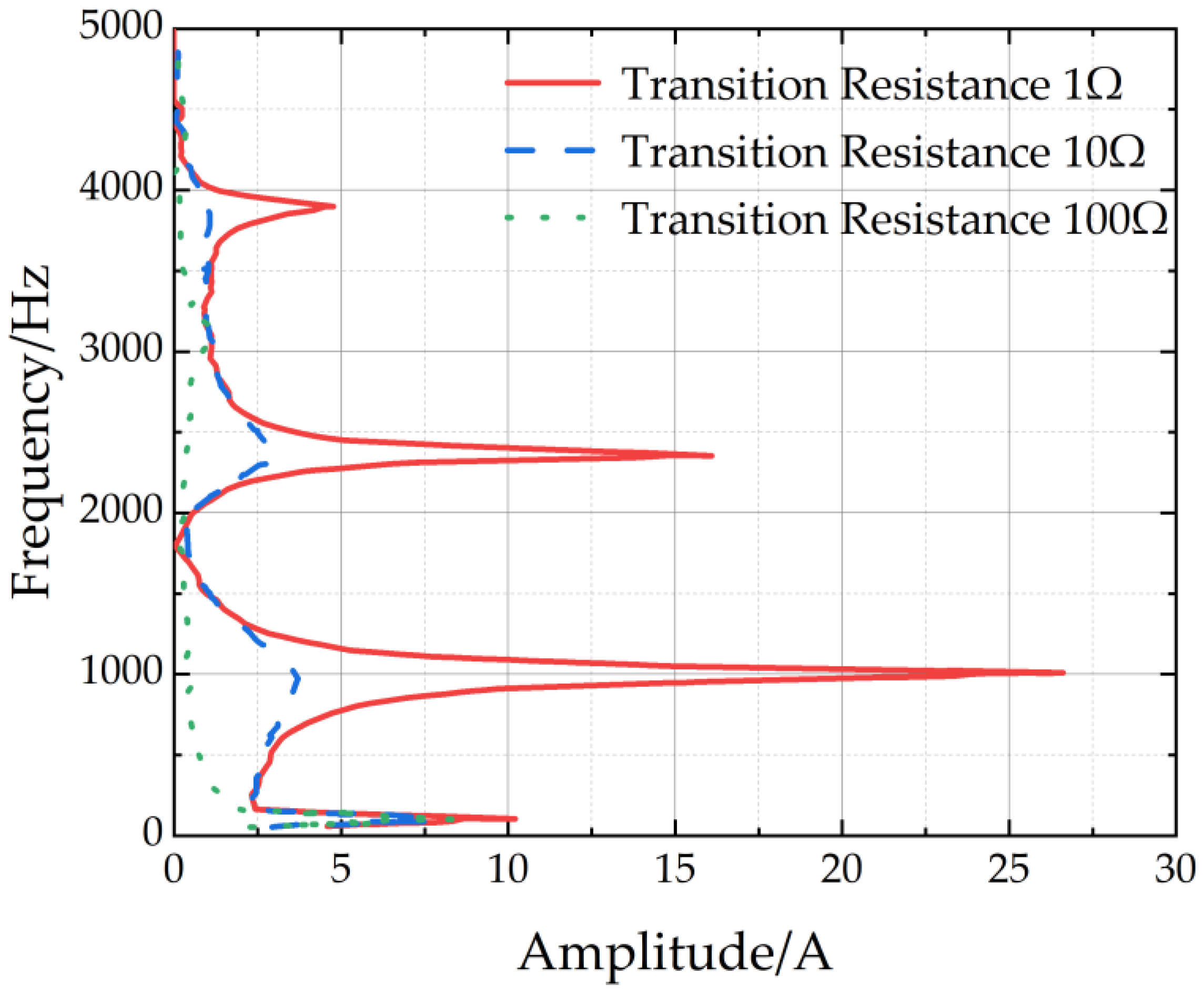
Here, we will investigate the impact of transition resistance on the zero-sequence current spectrum. The fault distance was kept to 3 km, with a closing angle of 90°. The transition resistance ranged from 1 Ω to 100 Ω. The zero-sequence current spectrum is shown in Figure 7. The larger the transition resistance, the more obvious the attenuation of each frequency component of the current spectrum. The degree of attenuation of the high-frequency component was greater than that of the industrial frequency and its nearby low-frequency components. As the transition resistance increased, the resonance peak of the current spectrum became less and less pronounced.
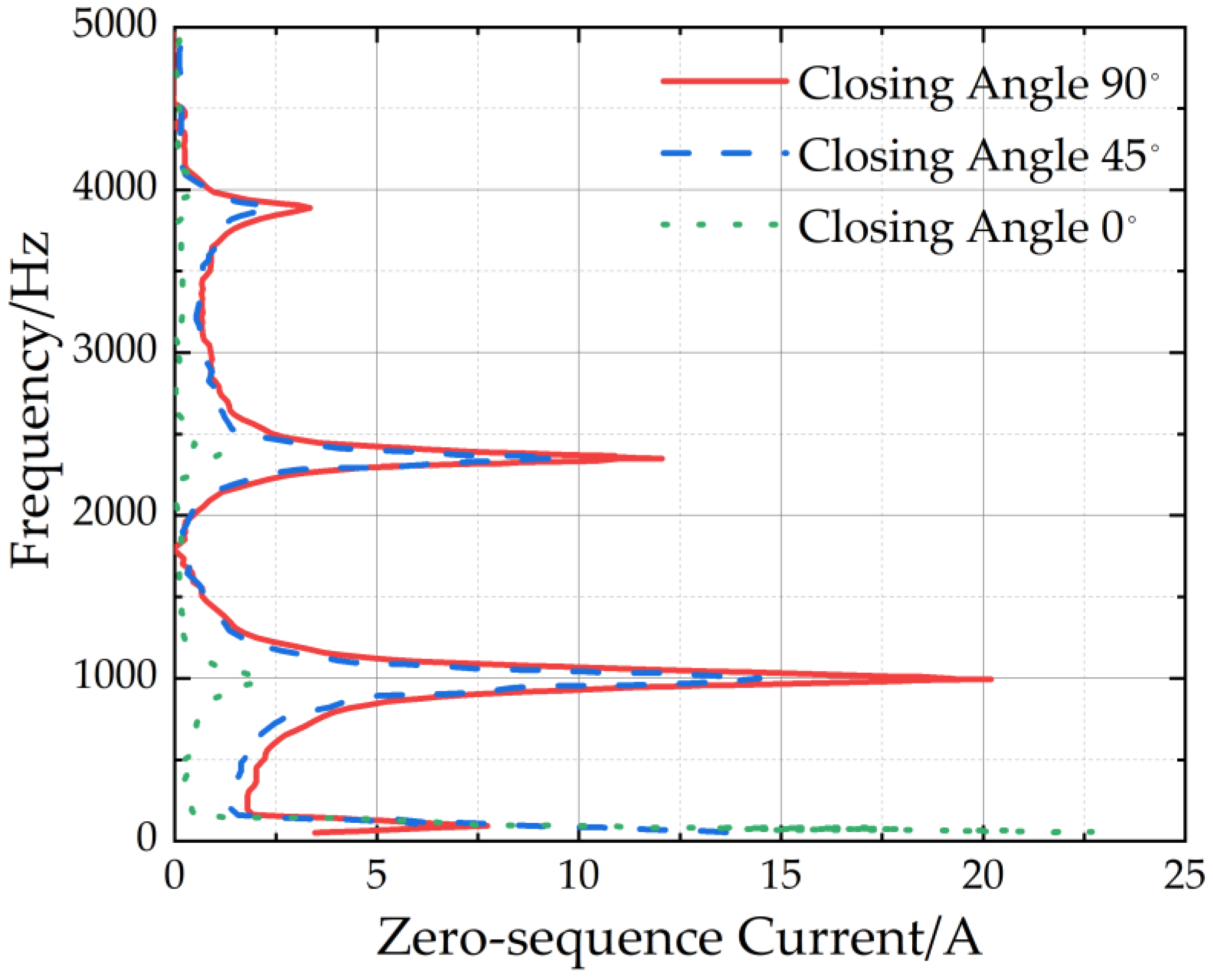
With the fault distance set to 3 km and the transition resistance to 1 Ω, we analyzed the fault closing angle in a range from 0° to 90°. As illustrated in Figure 8, it is evident that, as the fault closure angle approached 90°, the high-frequency component of the current increased. Conversely, as the fault closure angle approached 0°, the predominance of the DC component became more prominent. Nevertheless, the magnitude of the power frequency component remained relatively consistent across all three fault scenarios.

3. Location Method Based on Centroid Frequency

3.1. Centroid Frequency

From Figure 5, the equivalent impedance of Zos, upstream from the fault point, can be represented as follows:
Z o s = r x + j w L x + r L + j w L P 1 + ( r L + j w L P ) j w C
The equivalent admittance Yos, upstream of the fault point, can be represented as follows:
Y o s = 1 + ( r L + j w L P ) j w C [ 1 + ( r L + j w L P ) j w C ( r x + j w L x ) + r L + j w L P
The equivalent conductance Yox, downstream from the fault point, can be represented as follows:
Y o x = j w C y 1 + ( r y + j w L y ) j w C y
Under the same frequency, the admittance satisfies a corresponding relationship in Reference [34]. When we research these factors’ influences on the zero-sequence current spectrum, we can examine these factors by the frequency characteristics of the zero-sequence admittance.
However, it is crucial to note that the current spectrum is influenced by both voltage and admittance. In particular, the fault closing angle φ of the voltage has a significant impact on the high- and low-frequency components of the current spectrum. When φ equals 90°, the attenuation of the DC component is zero, while the high-frequency attenuation reaches its maximum. Conversely, when a single-phase-to-ground fault occurs with the voltage at zero, i.e., when φ is 0°, the high-frequency attenuation reaches its minimum and the DC attenuation is the highest. The spectral component concentrates in the low-frequency band.
It can be seen that, as the fault distance increases, the low-frequency component of the zero-sequence current spectrum also increases. This chapter defines the centroid frequency of the spectrum fG [35].
Physically, the centroid of an object with a vector diameter is the sum of the product of the mass mi of each micro point on the object and its vector diameter, divided by the total mass of the object, which can be represented by Equation (6), as follows:
r c = i = 1 n m i r i i = 1 n m i
The centroid vector diameter of an object represents the vector that points from the coordinate origin to the object’s centroid. This vector reflects the location of the center of the object’s overall mass. The spectral centroid frequency fG is then derived from the resulting centroid vector diameter [36], as follows:
f G = f 1 = 0 f n = 1 / 4 l k L 0 k C 0 k f i H i f 1 = 0 f n = 1 / 4 l k L 0 k C 0 k H i
where Hi is the spectral amplitude corresponding to the frequency fi; L0k, C0k, and lk are the zero-sequence inductance, zero-sequence capacitance, and length per unit of the faulty line, respectively; and the upper limit of fi is 1/4l L 0 k C 0 k , taken as the first resonant frequency of the line.
According to the fault location equivalent circuit, the zero-sequence current at the first end of the faulty feeder is as follows:
I · ( w ) = Y o s Y o s + Y o x 1 1 Y o s + Y o x + 3 R f U · ( w )
Yos and Yox are the equivalent conductance upstream and downstream of the fault point, respectively. Equation (8) gives the current frequency component influence factor, which depends partly on the voltage frequency component and partly on the conductance. When studying the conductance aspect factor, the centroid frequency of the zero-sequence current spectrum at the first end of the faulted line is obtained using the conductance approximation. The equivalent conductance is obtained using Equation (8).
Y ( w ) = Y o s Y o s + Y o x 1 1 Y o s + Y o x + 3 R f = Y o s 1 + 3 R f ( Y o s + Y o x )
The current frequency components are approximately equal and we can obtain them using the following:
I · ( w ) Y ( w )
Bringing (9) and (10) into (7) yields the following:
w G = w = 0 w = π / 2 l k L 0 k C 0 k w Y o s ( w ) 1 + 3 R f ( Y o s ( w ) + Y o x ( w ) ) w = 0 w = π / 2 l k L 0 k C 0 k Y o s ( w ) 1 + 3 R f ( Y o s ( w ) + Y o x ( w ) )
In order to locate faults in the three feeder systems described previously, a simulation model was established by setting the following parameters: rL = 15.447 Ω, Lp = 1.6389 H, ∑C = (2.544 × 10⁻⁶ + Cx)F, Lx = 0.892 × 10⁻³ lH, rx = 0.102 lΩ, Cx = 0.212 × 10⁻⁶ lF, Ly = 0.892 × 10⁻³(6 − l)H, ry = 0.102(6 − l)Ω, and Cy = 0.212 × 10⁻⁶(6 − l)F, where l is the fault distance.
The first resonant frequency of each feeder line was calculated to be 3029 Hz. At this frequency, the input impedance of the sound line was approximately zero. As a result, the current spectrum of the fault line in Figure 9 peaked near 3000 Hz, while the current spectrum in the frequency range of 0–3000 Hz showed a left-shift characteristic as the fault distance increased. In contrast, the previous peak occurred near 1000 Hz, and its main resonant frequency was approximately 1000 Hz, which was lower than the first resonance frequency.
The relationship between the centroid frequency and fault distance is illustrated in Figure 10. The graph clearly demonstrates that the increase in the fault distance led to a decrease in the centroid frequency of the zero-sequence transient fault current spectrum. Furthermore, the longer fault distances caused a leftward shift in the current spectrum.
This observation suggests the relationship between fault distance and centroid frequency. It is crucial to recognize that this relationship may demonstrate that there exists either a monotonic decrease or fluctuation; therefore, recognizing the relationship between fault distance and centroid frequency can be beneficial for fault location.
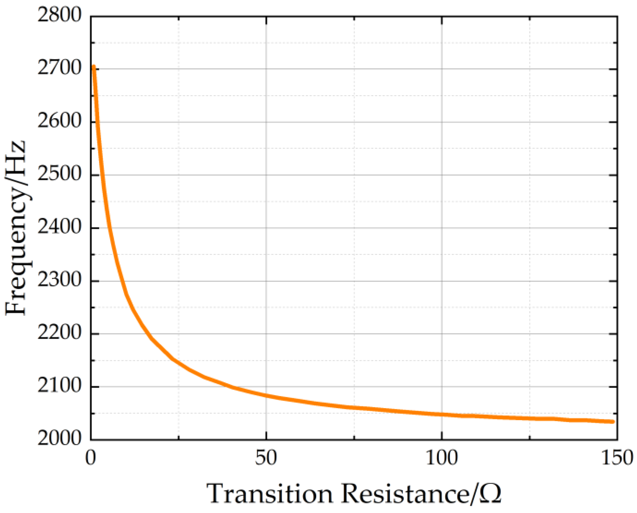
Similarly, we can obtain the curve between the centroid frequency and transient resistance, as shown in Figure 10. It can be observed that, as the transient resistance increased, the centroid frequency gradually decreased.

3.2. Location Principle

In this chapter, a three-layer BPNN [37] was established, to simulate the functional relationship F. The input layer of this neural network has three neurons, namely the fault closing angle, fault distance, and transition resistance; the output layer has one neuron, namely centroid frequency.

3.2.1. Fundamentals

The BPNN is capable of acquiring the curve of any closing angle and transition resistance [38]. In the event of an asymmetrical fault, the fault line is initially determined by the line selection algorithm, while the closing angle can be obtained from the oscilloscope. The transition resistance is calculated using the appropriate method, as in Reference [39]. Subsequently, the BPNN is employed to simulate the curve under the fault condition. By analyzing the transient current samples within the corresponding frequency band, the spectral centroid frequency can be determined, enabling the calculation of the fault distance.
During the simulation, it was observed that the function fG = F (φ, R, x) exhibited non-monotonic behavior when a specific line within the distribution network occurred to a fault. This phenomenon led to non-monotonic relationship curves between centroid frequencies and fault distances [40].
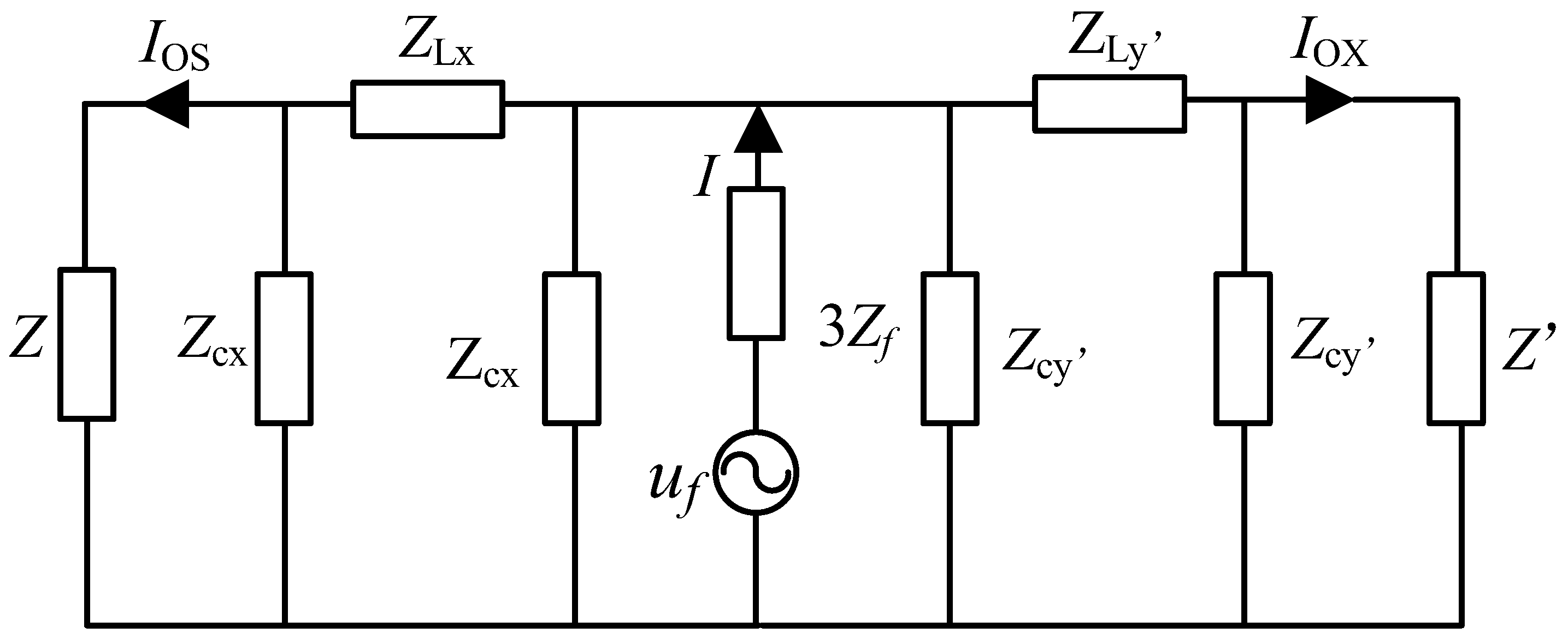
The centroid frequency can remain constant when different fault conditions happen. But one centroid frequency may correspond to different fault distances. Consequently, auxiliary criteria are essential for a more precise determination of the fault distance. The zero-sequence π-equivalent circuit for fault distance measurement is illustrated in Figure 11 [41].
Z is the equivalent impedance of the sound line and the arc-absorbing coil. I is a frequency component of the transient zero-sequence current. uf is the fault voltage. Ios is the zero-sequence current at the bus bar of the fault line, and Iox is the zero-sequence current at the end of the line at 0.5 km [42]. After derivation, the ratio λ of the same frequency component of the current at the first and last ends of the fault line can be obtained, as follows:
λ w = ( Z c y Z Z c y + Z + Z L y ) Z c y ( Z c x Z Z c x + Z + Z L x ) Z c x
Here, Zcx and Zcy’ are inversely proportional to x and y’, respectively, ZLx and ZLy’ are proportional to x and y’, respectively, and x + y’ = C, C is a constant. x is the distance of the fault, while y’ denotes the distance from the fault point to the end of the line at 500 m. All of the definitions are collected in the Appendix A. For determining a particular faulted feeder in the distribution network, Z and Z’ are constants from Reference [43]. From (12), it can be seen that λ is a function of the distance x from the fault. The amplitude of the corresponding frequency components of the current spectrum at the two monitoring points was compared to obtain λ. The mean value of λ for each frequency component in the range of the first resonance frequency was used as the output. The fault closing angle, transition resistance, and fault distance were used as inputs to complete the neural network training.
Using the BPNN method for locating may yield one or two results, while the λ neural network can provide multiple location results. In principle, correct location results should not deviate significantly, and they are accordingly subjected to filtering processes.
A neural network was applied after a ground fault occurred, to give the fault distance–centroid frequency relationship curve (xi, λi) and the fault distance–λ relationship curve (xi, λi). The actual fault distance and centroid frequency were set to be (x, fG), where x was a value to be determined and fG was calculated from the monitored zero-sequence current.

3.2.2. Determination of Fault Location

The monotonicity of the fault distance–centroid frequency relationship curve was first determined using the following equation [44]:
Δ f G i Δ x i Δ f G j Δ x j 0     i , j = 1 , 2 , 3 n
where n is the number of curve points. If the above equation holds, then there is no need to apply the fault distance–λ relationship curve to assist the determination of the location [45].
We calculated the absolute difference between the frequency relationship curve fGi and the actual fG, as follows:
d i = f G i f G
The two with the smallest absolute difference were selected, and their corner markers were j and k. If the difference between xj and xk is less than 1 km, it means that the centroid frequency curve was monotonous in the vicinity of the location results or that the actual fault distance is located in the interval formed by the two location results, meaning that the auxiliary location method is still not needed, and the mean value of xj and xk is the final result; if the difference between xj and xk is greater than or equal to 1 km, then auxiliary criterion is needed.
We calculated the absolute difference between the fault distance–λ relationship curve, λi, and the actual λ, as follows:
D i = λ i λ
We selected the two with the smallest absolute difference, whose angle markers were p and m, and the location results were xp and xm. We then calculated the absolute difference between the centroid frequency curve and the location results of the λ curve, as follows:
Δ X 1 = x j x p Δ X 2 = x j x m Δ X 3 = x k x p Δ X 4 = x k x m
The minimum values of X 1 ,  X 2 , X 3 , and X 4 were selected, corresponding to the two curve location results as xi1 and xi2, respectively, and the average value was taken as the final comprehensive location result.

3.3. Procedure

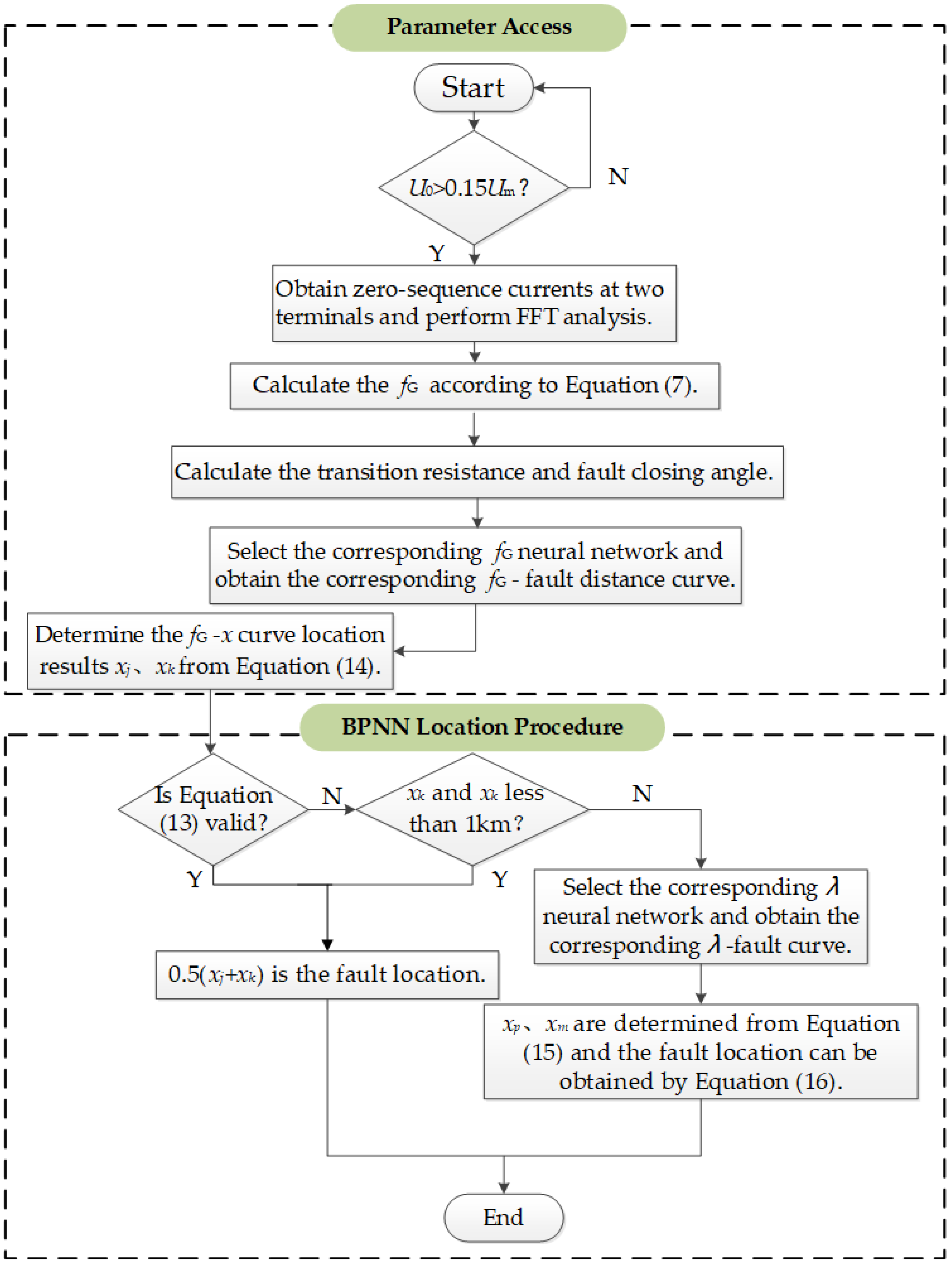
Figure 12 shows the flow chart of the location algorithm. First of all, according to the bus zero sequence voltage U0, which was used to determine whether the line had an asymmetrical fault, when U0 is greater than 15% of the rated phase voltage, we needed to start the distance measurement algorithm program.
The transient fault current collected at both ends of the line was transformed by FFT (Fast Fourier Transform) to extract the frequency components, and the centroid frequency fG and auxiliary criterion indicators were calculated, according to the current spectrum. The determination of the fault closing angle was facilitated through oscilloscope analysis. The resistance of the transition resistor was then computed, employing established methodologies. Then, we used the BPNN to obtain the fault distance curve under the transition resistance value and fault closing angle, using Equation (14) to obtain the centroid frequency curve and two distance measurement results, xj and xk. If, at this time, Equation (15) was valid, indicating that the centroid frequency curve was monotonic, then the average value of xj and xk provided the final location results. If Equation (14) did not hold, we continued determining whether the difference between xj and xk was less than 1 km, we still used the average value of xj and xk for the final location of the results; otherwise, the use of λ neural network gave the λ–fault distance curve for this fault condition, and then gave the λ curve location results xp and xm according to (15), which were then combined with (16) to determine the final localization results.

3.4. Simulation

The simulation model is shown in Figure 13, which consisted of four feeder lines, including a hybrid line, branch line, overhead line, and a cable line. The thin lines denote the overhead line, while the thick lines represent the cable line. The current detection device was installed at the bus and the branch line. The overhead line parameters were set as follows: R1 = 0.17 Ω/km, R0 = 0.23 Ω/km, L1 = 1.2096 × 10⁻³ H/km, L0 = 5.4749 × 10⁻³ H/km, C1 = 0.0097 × 10⁻⁶ F/km, and C0 = 0.006 × 10⁻⁶ F/km. The cable line parameters were set as follows: R1 = 0.075 Ω/km, R0 = 0.102 Ω/km, L1 = 0.254 × 10⁻³ H/km, L0 = 0.892 × 10⁻³ H/km, C1 = 0.318 × 10⁻⁶ F/km, and C0 = 0.212 × 10⁻⁶ F/km. The compensation degree was 5%, the inductance of the arc coil was L = 0.45 H, and the resistance of the coil was R = 4.233 Ω.
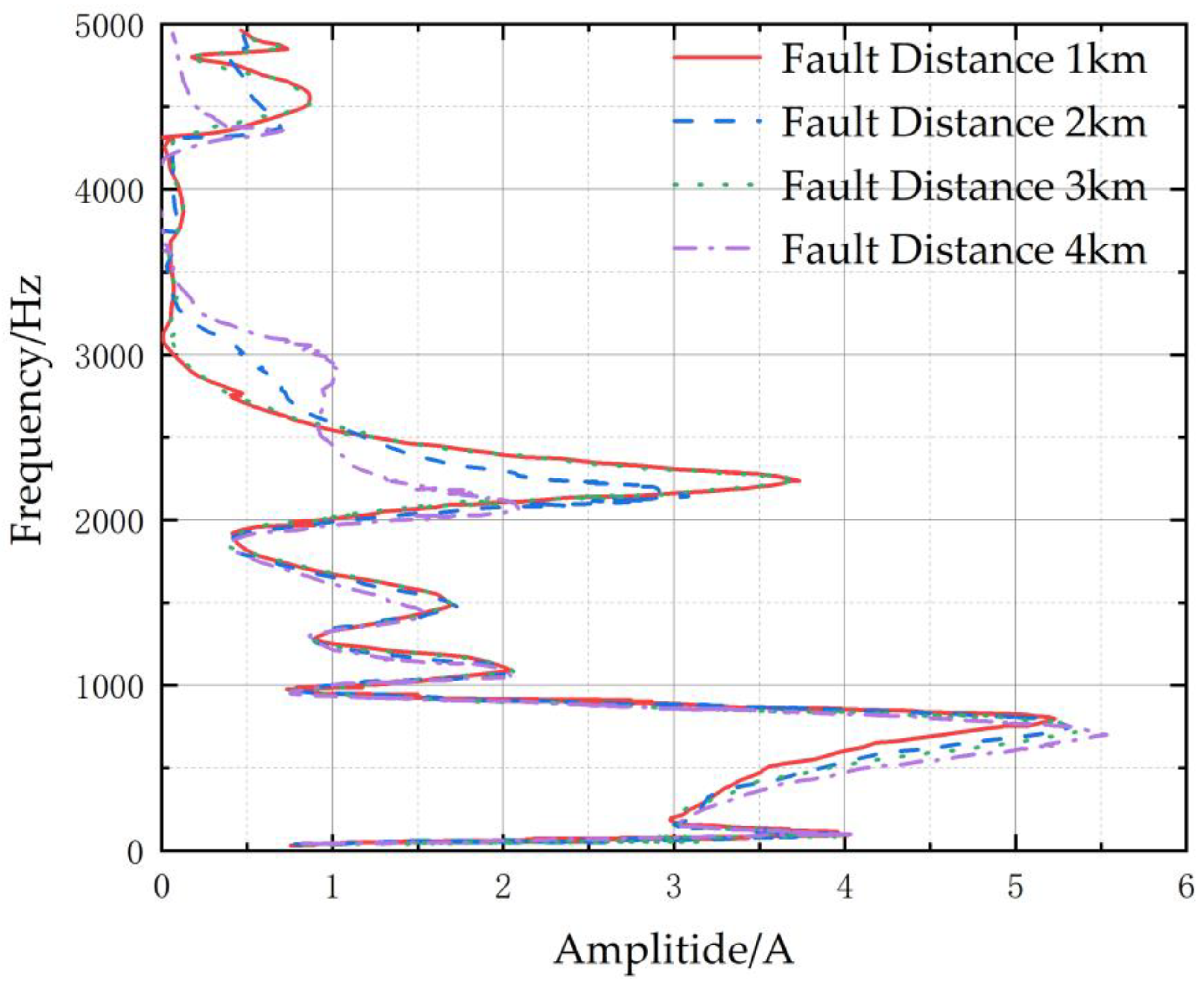
The transient zero-sequence current spectra for line 2 with a closing angle of 90°, a transition resistance of 10 Ω, and fault distances of 1 km, 2 km, 3 km, and 4 km are shown in Figure 14. The first resonant frequency of line 2 was 2597 Hz. In the frequency range of 0–2597 Hz, the larger the fault distance, the more the overall distribution of the spectrum moved to the left.
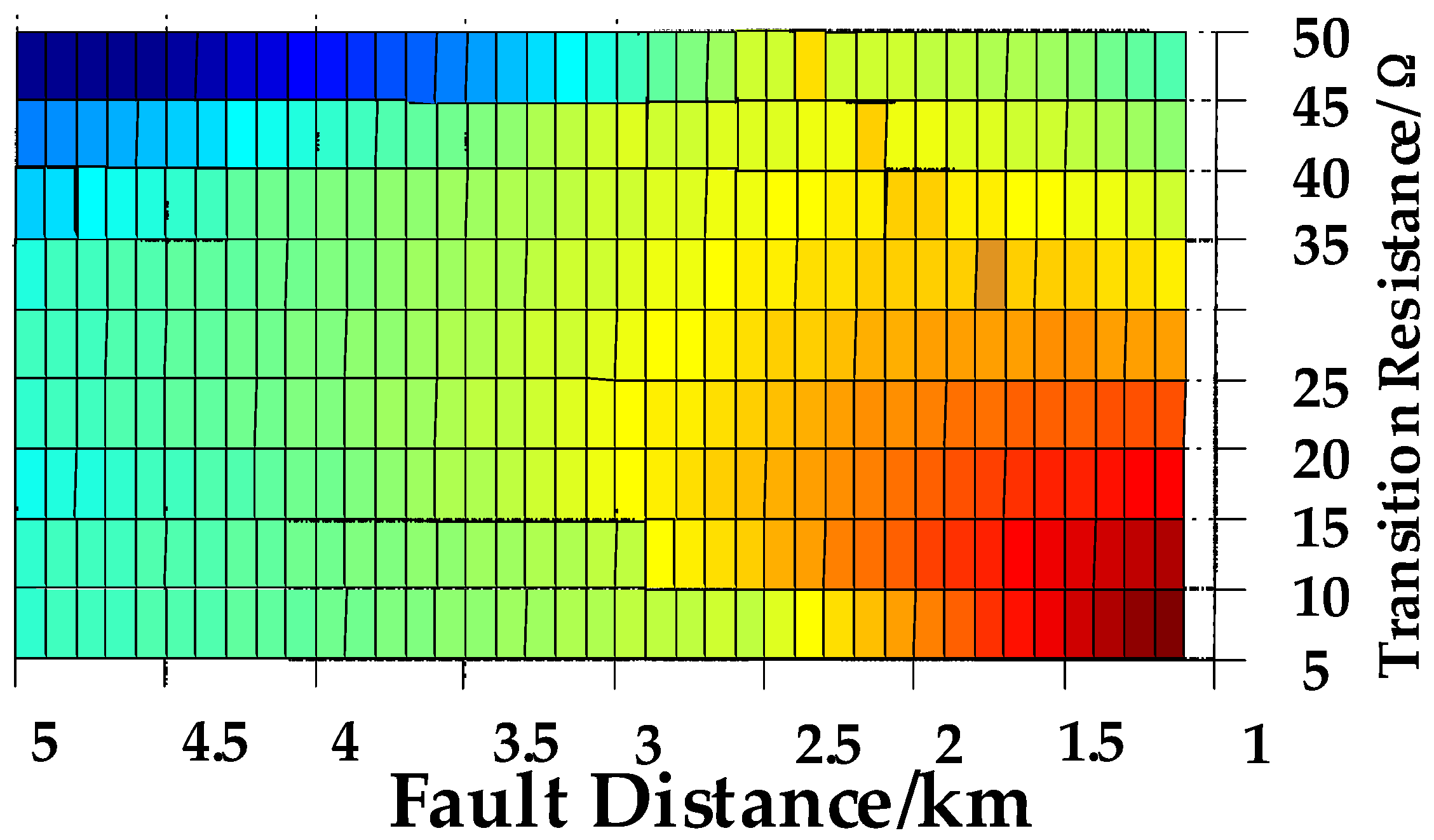
When the fault with a fault closing angle of 90° happens on line 2. Based on the BPNN, the relationship between transition resistance, fault distance, and the centroid frequency spectrum was provided. As illustrated in Figure 15, the color gradient from red to blue represents the centroid frequency decreasing from high to low. When the transition resistance was small, the centroid frequency monotonically decreased with an increasing fault distance. However, with a larger transition resistance, as the fault distance increased, the centroid frequency reached its peak, with a monotonic trend of increasing and then decreasing with fault distance.
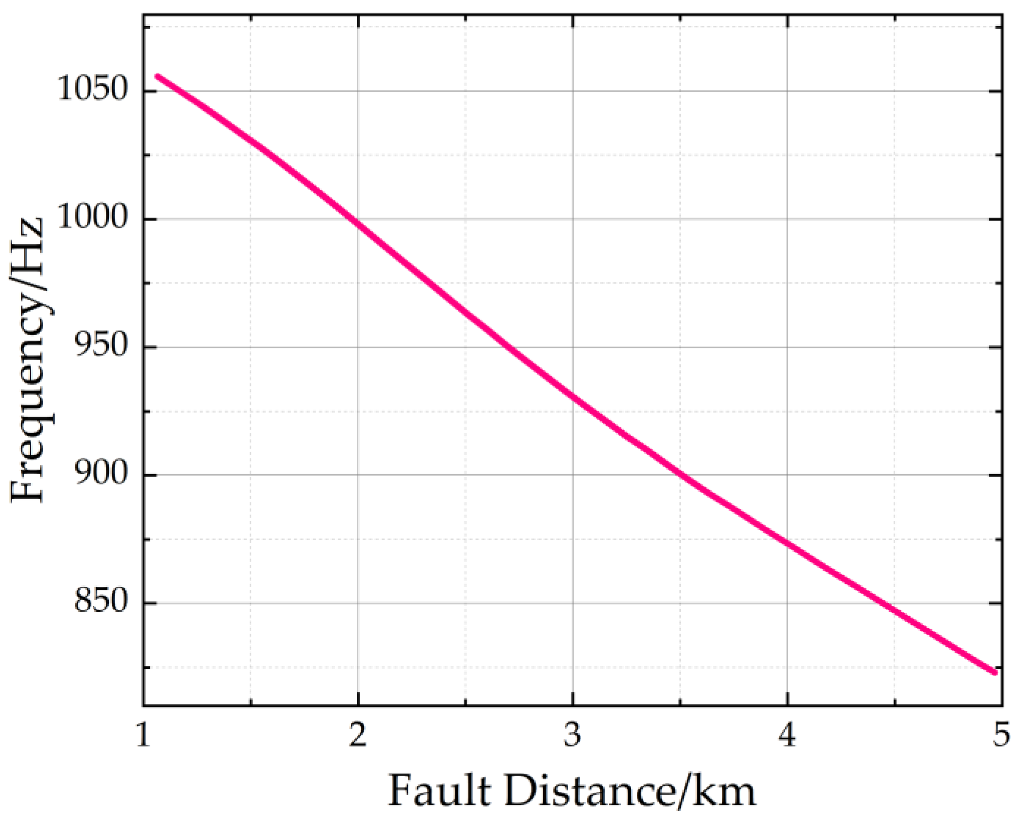
The results are shown in Table 1. It can be seen that the location method was effective. The error of each result was within 50 m. The curve is shown in Figure 16 for a fault on line 2, with a transition resistance of 10 Ω and a 90° fault closing angle. According to the location algorithm, the curve was monotonic and did not require a λ curve for location.
The relationship curve is depicted in Figure 17, demonstrating a non-monotonic pattern, for a single-phase-to-earth fault on line 2, characterized by a transition resistance of 50 Ω and a closing angle of 90°.
At a fault distance of 1.5 km, the curve provided location results of 1.53 km and 2.8 km. To enhance accuracy, the λ curve was employed for distance measurement, as illustrated in Figure 18.
The resulting distance measurements from the λ curve were 1.44 km and 3.41 km. By selecting the average of 1.53 km and 1.44 km, a more reliable distance estimation was obtained. For a fault distance of 2 km, the curve yielded a result of 1.87 km and 2.2 km, with minimal disparity. This suggests that the fault point was situated within the interval of [1.87 km, 2.2 km], obviating the need for the λ curve in locating the fault. Similarly, at a fault distance of 4 km, the centroid frequency curve produced location results of 3.96 km and 3.97 km, indicating a negligible difference between the two measurements. This signified a monotonic behavior in the centroid frequency curve near the results, and, according to the automatic location algorithm, the use of the λ curve for locating the fault was unnecessary.
In future works, we will further optimize the BPNN to reduce location errors. Currently, the methods under consideration include the heap-based optimizer (HBO) and the modified gradient-based algorithm.
Compared to most existing algorithms, HBO has a very simple structure, and the involved formulas are easy to understand. Moreover, there are numerous ways to improve the algorithm.
Gradient descent is one of the most popular algorithms for optimization and remains the most commonly used method for optimizing neural networks. Additionally, every modern deep learning library includes various implementations of optimization algorithms tailored for gradient descent.

4. Conclusions

This paper investigated the effects of transition resistance, fault distance, and fault closing angle on the spectrum of a zero-sequence current, elucidating their underlying mechanisms through an equivalent circuit. To summarize the characteristics, we extracted the centroid frequency. A lower centroid frequency indicated a spectral energy distribution closer to the low-frequency band. In the proposed method, the interaction between centroid frequency and fault conditions was carefully studied through equivalent derivative analysis. The relationship between fault conditions and centroid frequency was simulated using a BPNN, and an auxiliary criterion was proposed, to address scenarios where the curve of the centroid frequency–fault distance relationship exhibited non-monotonic behavior. The results demonstrated the effectiveness of the proposed method, with errors within 50 m.

Author Contributions

R.Z. was responsible for the literature review; J.L. served as the mentor, providing guidance on techniques and writing methodologies; Q.C. collaborated in conducting experiments and recording data; N.Z. helped with supervision; H.L. detected the mistakes and polished the article. All authors have read and agreed to the published version of the manuscript.

Funding

This work was supported by the Key Science and Technology Project of China Southern Grid 032000KK52222029 (GDKJXM20222496).

Data Availability Statement

Data are contained within the article.

Conflicts of Interest

The authors Ruifeng Zhao, Jiangang Lu, and Qizhan Chen were employed by China Southern Power Grid Company Limited. The remaining authors declare that the research was conducted in the absence of any commercial or financial relationships that could be construed as a potential conflict of interest.

Appendix A

Table A1. Definition.
VariableDefinition
rxUpstream resistance from the fault point.
LxUpstream inductance from the fault point.
ryDownstream resistance from the fault point.
LyDownstream inductance from the fault point.
rLGrounding resistance.
LpGrounding inductance.
RfTransition resistance.
Pout, QoutThe instantaneous output active power and reactive power of DG
uP,qq-axis component of instantaneous output active power.
uP*PCC voltage standard unit value.
K1, K2, KmaxVoltage support factor, reactive current peak factor, and overload current multiple.
IDGRRated current.
ZosEquivalent impedance.
YosEquivalent admittance.
fGCentroid frequency.
HiSpectral amplitude.
L0kZero-sequence inductance per unit.
C0kZero-sequence capacitance per unit.
lkLength per unit.
ZEquivalent impedance of the sound line
uffault voltage.
IosZero-sequence current at the bus of the fault line.
IoxZero-sequence current at the end of the line at 0.5 km.
λThe ratio of the same frequency component of the current at the starting and ending ends of the faulted line circuit.
Zcx, Zcy’, ZLx, ZLyParameters in the π equivalent circuit of single-phase earth fault.

References

  1. Abeysinghe, S.; Abeysekera, M.; Wu, J. Electrical properties of medium voltage electricity distribution networks. CSEE J. Power Energy Syst. 2020, 7, 497–509. [Google Scholar]
  2. Dashti, R.; Daisy, M.; Mirshekali, H. A survey of fault prediction and location methods in electrical energy distribution networks. Measurement 2021, 184, 109947. [Google Scholar] [CrossRef]
  3. Hussain, S.; Razi, F.; Hewage, k. The perspective of energy poverty and 1st energy crisis of green transition. Energy 2023, 275, 127487. [Google Scholar] [CrossRef]
  4. Guo, K.; Luan, L.; Cai, X. Energy trade stability of China: Policy options with increasing climate risks. Energy Policy 2024, 184, 113858. [Google Scholar] [CrossRef]
  5. Ahmad, F.; Iqbal, A.; Ashraf, I. Optimal location of electric vehicle charging station and its impact on distribution network: A review. Energy Rep. 2022, 8, 2314–2333. [Google Scholar] [CrossRef]
  6. Yang, W.; Yin, X.; Tao, J. Fault current constrained impedance-based method for high resistance ground fault location in distribution grid. Electr. Power Syst. Res. 2024, 227, 109998. [Google Scholar] [CrossRef]
  7. Boštjan, P.; Matej, P.; Janez, R.; Miran, R.; Gorazd, Š. Parametrization of ground-fault relays in MV distribution networks with resonant grounding. Int. J. Electr. Power Energy Syst. 2022, 143, 108449. [Google Scholar]
  8. Cao, L.; Fang, R.; Zhang, Y. Analysis of the impact of distributed power access in distribution networks. Power Energy 2023, 44, 622–624. [Google Scholar]
  9. Wang, Q.; Xiao, Y.; Dampage, U. An effective fault section location method based three-line defense scheme considering distribution systems resilience. Energy Rep. 2022, 8, 10937–10949. [Google Scholar] [CrossRef]
  10. Moisés, J.; Davi, M.; Felipe, V. An impedance-multi-method-based fault location methodology for transmission lines connected to inverter-based resources. Int. J. Electr. Power Energy Syst. 2023, 154, 109466. [Google Scholar]
  11. García-Ceballos, C.; Pérez-Londoño, S.; Mora-Flórez, J. Compensated fault impedance estimation for distance-based protection in active distribution networks. Int. J. Electr. Power Energy Syst. 2023, 151, 109114. [Google Scholar] [CrossRef]
  12. Sayed, H.; Mohammad, E. Fault location observability rules for impedance-based fault location algorithms. Electr. Power Syst. Res. 2023, 224, 109771. [Google Scholar]
  13. da Silva Pessoa, A.L.; Oleskovicz, M. Fault location algorithm for distribution systems with distributed generation based on impedance and metaheuristic methods. Electr. Power Syst. Res. 2023, 225, 109871. [Google Scholar] [CrossRef]
  14. Reyhaneh, T.; Mahdiyeh, E.; Yaser, D. A current-based algorithm for one-end fault location in series capacitor compensated double-circuit transmission lines. Comput. Electr. Eng. 2023, 106, 108618. [Google Scholar]
  15. Tian, X.; Liu, Z.; Shan, J. Identification of overhead line fault traveling wave and interference clutter based on convolution neural network and random forest fusion. Energy Rep. 2023, 9, 1531–1545. [Google Scholar] [CrossRef]
  16. Zhao, J.; Hou, H.; Gao, Y. Single-phase ground fault location method for distribution network based on traveling wave time-frequency characteristics. Electr. Power Syst. Res. 2020, 186, 106401. [Google Scholar]
  17. Davod, R.; Mehdi, G.; Farzad, P. A single-ended traveling-wave-based fault location for a hybrid transmission line using detected arrival times and TW’s polarity. Electr. Power Syst. Res. 2022, 210, 108058. [Google Scholar]
  18. Alberto, J.; Guillen, D.; Tapia-Olvera, R.; Escobar, G. An improved algorithm for fault detection and location in multi-terminal transmission lines based on wavelet correlation modes. Electr. Power Syst. Res. 2021, 192, 106953. [Google Scholar]
  19. Zhang, Y.; Cong, W. An improved single-ended frequency-domain-based fault detection scheme for MMC-HVDC transmission lines. Int. J. Electr. Power Energy Syst. 2021, 125, 106463. [Google Scholar] [CrossRef]
  20. Bertoletti, A.; Cardoso, G.; de Peres, A. Ground and phase fault classification for half-wavelength transmission lines relaying purposes. Int. J. Electr. Power Energy Syst. 2023, 148, 108966. [Google Scholar] [CrossRef]
  21. Pirmani, S.; Mahmud, A. Advances on fault detection techniques for resonant grounded power distribution networks in bushfire prone areas: Identification of faulty feeders, faulty phases, faulty sections, and fault locations. Electr. Power Syst. Res. 2023, 220, 109265. [Google Scholar] [CrossRef]
  22. Peng, N.; Zhang, P.; Liang, R.; Guo, Z.; Hu, Y. Fault location of three-core power distribution cables based on lump-parameter model considering conductor couplings. Int. J. Electr. Power Energy Syst. 2021, 130, 106953. [Google Scholar] [CrossRef]
  23. Treider, T.; Høidalen, H. Estimating distance to transient and restriking earth faults in high-impedance grounded, ring-operated distribution networks using current ratios. Electr. Power Syst. Res. 2023, 224, 109765. [Google Scholar] [CrossRef]
  24. Penaloza, J.; Borghetti, A.; Napolitano, F.; Tossani, F. Performance analysis of a transient-based earth fault protection system for unearthed and compensated radial distribution networks. Electr. Power Syst. Res. 2021, 197, 107306. [Google Scholar] [CrossRef]
  25. Ghorbani, A.; Mehrjerdi, H. Accurate fault location algorithm for shunt-compensated double circuit transmission lines using single end data. Int. J. Electr. Power Energy Syst. 2020, 116, 105515. [Google Scholar] [CrossRef]
  26. Hossam, A.; Soliman, I.; Ahmed, E. Generalized wide-area fault detection and location algorithm for transmission system based on optimal PMUs allocation. Int. J. Electr. Power Energy Syst. 2024, 155, 109634. [Google Scholar]
  27. Li, C.; Wu, H.; Zhang, L.; Shan, H. Two-stage fault section location for distribution networks based on compressed sensing with estimated voltage measurements. Electr. Power Syst. Res. 2023, 223, 109702. [Google Scholar] [CrossRef]
  28. Liang, Y.; He, A.; Yuan, J. An accurate fault location method for distribution lines based on data fusion of outcomes from multiple algorithms. Int. J. Electr. Power Energy Syst. 2023, 153, 109290. [Google Scholar] [CrossRef]
  29. Mohammad, F.; Mahmood, J.; Alireza, S.; Mehdi, M. A single-ended traveling wave-based fault location method using DWT in hybrid parallel HVAC/HVDC overhead transmission lines on the same power. Electr. Power Syst. Res. 2023, 220, 109302. [Google Scholar]
  30. Bai, H. Single-phase grounding fault line selection method based on zero-sequence current increment. Energy Rep. 2022, 8, 305–312. [Google Scholar]
  31. Xu, D. A New Efficient Bidirectional T-Source Circuit Breaker for Flexible DC Distribution Networks. IEEE J. Emerg. Sel. Top. Power Electron. 2020, 9, 7056–7065. [Google Scholar]
  32. Xu, R.; Song, G.; Chang, Z. A ground fault section location method based on active detection approach for non-effectively grounded DC distribution networks. Int. J. Electr. Power Energy Syst. 2023, 152, 109174. [Google Scholar] [CrossRef]
  33. Wang, Z.; Leng, Y.; Qiu, X. Reconfigurable bandpass filter with flexible tuning of both center frequency and bandwidth. Int. J. Electron. Commun. 2024, 173, 155027. [Google Scholar] [CrossRef]
  34. Sergio, U.; Molina-Pineda, A. A center-of-gravity-based framework for small- and large-signal frequency analysis of interconnected power systems. Electr. Power Syst. Res. 2023, 223, 109677. [Google Scholar]
  35. Hussain, M.; Dhimish, M.; Titarenko, S. Artificial neural network based photovoltaic fault detection algorithm integrating two bi-directional input parameters. Renew. Energy 2020, 155, 1272–1292. [Google Scholar] [CrossRef]
  36. Guo, J.; Wang, X.; Ooi, B. Online purely data-driven estimation of inertia and center-of-inertia frequency for power systems with VSC-interfaced energy sources. Int. J. Electr. Power Energy Syst. 2022, 137, 107643. [Google Scholar] [CrossRef]
  37. Siddique, M.; Shafiullah, M.; Mekhilef, S. Fault classification and location of a PMU-equipped active distribution network using deep convolution neural network (CNN). Electr. Power Syst. Res. 2024, 229, 110178. [Google Scholar] [CrossRef]
  38. Mirshekali, H.; Dashti, R.; Keshavarz, A. A novel fault location methodology for smart distribution networks. IEEE Trans. Smart Grid 2020, 12, 1277–1288. [Google Scholar] [CrossRef]
  39. Mohammad, D.; Rahman, D.; Hamid, R. Fault location in power grids using substation voltage magnitude differences: A comprehensive technique for transmission lines, distribution networks, and AC/DC microgrids. Measurement 2023, 220, 113403. [Google Scholar]
  40. Vishal, K.; Bhavesh, R.; Ahmed, S. New ground fault location method for three-terminal transmission line using unsynchronized current measurements. Int. J. Electr. Power Energy Syst. 2022, 135, 107513. [Google Scholar]
  41. Tesfaye, A.; Thomas, T.; Lars, B. Two novel current-based methods for locating earth faults in unearthed ring operating MV networks. Electr. Power Syst. Res. 2022, 213, 108774. [Google Scholar]
  42. Ghaemi, A.; Safari, A.; Afsharirad, H. Accuracy enhance of fault classification and location in a smart distribution network based on stacked ensemble learning. Electr. Power Syst. Res. 2022, 205, 107766. [Google Scholar] [CrossRef]
  43. David, T.; Matti, L.; Petr, T. An earth fault location method based on negative sequence voltage changes at low voltage side of distribution transformers. Int. J. Electr. Power Energy Syst. 2020, 118, 105768. [Google Scholar]
  44. Askari, Q.; Saeed, M.; Younas, I. Heap-based optimizer inspired by corporate rank hierarchy for global optimization. ESA 2020, 161, 113702. [Google Scholar] [CrossRef]
  45. El-Rifaie, A.M.; Shaheen, A.M.; Tolba M, A. Modified Gradient-Based Algorithm for Distributed Generation and Capacitors Integration in Radial Distribution Networks. IEEE Access 2023, 11, 120899–120917. [Google Scholar] [CrossRef]
Figure 1. Applications of an intelligent algorithm to the power system.
Electronics 13 01491 g001
Figure 2. Centralized photovoltaic power generation system.
Electronics 13 01491 g002
Figure 3. Distributed photovoltaic power generation system.
Electronics 13 01491 g003
Figure 4. Schematic diagram of a DG access system bus.
Electronics 13 01491 g004
Figure 5. Zero-sequence equivalent circuit.
Electronics 13 01491 g005
Figure 6. Transient short-circuit current frequency spectrums for different fault distances.
Electronics 13 01491 g006
Figure 7. Transient short-circuit current frequency spectrums for different transition resistances.
Electronics 13 01491 g007
Figure 8. Transient short-circuit current frequency spectrums for different fault closing angles.
Electronics 13 01491 g008
Figure 9. The relationship between fault distance and centroid frequency (1 Ω).
Electronics 13 01491 g009
Figure 10. The relationship between transition resistance and centroid frequency.
Electronics 13 01491 g010
Figure 11. Fault location π-equivalent circuit of single-phase earth fault.
Electronics 13 01491 g011
Figure 12. Fault location algorithm flow chart.
Electronics 13 01491 g012
Figure 13. Simulation model.
Electronics 13 01491 g013
Figure 14. Zero-sequence current frequency spectra of line 2.
Electronics 13 01491 g014
Figure 15. Centroid frequency of different fault distances and transition resistances.
Electronics 13 01491 g015
Figure 16. The relationship between centroid frequency and fault distance of line 2 (10 Ω).
Electronics 13 01491 g016
Figure 17. The relationship between centroid frequency and distance of line 2 (50 Ω).
Electronics 13 01491 g017
Figure 18. The relationship between λ and distance of line 2 (50 Ω).
Electronics 13 01491 g018
Table 1. The results of fault location.
Fault ConditionfG Resultsλ ResultsResults
Line 2, 2 km, 10 Ω, 90°2.03 km, 2.02 kmNo2.025 km
Line 2, 3 km, 10 Ω, 90°3.02 km, 3.01 kmNo3.015 km
Line 2, 1.5 km, 50 Ω, 90°1.53 km, 2.8 km1.44 km, 3.41 km1.485 km
Line 2, 2 km, 50 Ω, 90°1.87 km, 2.2 kmNo2.035 km
Line 2, 4 km, 50 Ω, 90°3.96 km, 3.97 kmNo3.965 km
Line 5, 1.5 km, 45 Ω, 90°1.48 km, 1.49 kmNo1.485 km
Line 3, 6 km, 25 Ω, 90°6.01 km, 6.02 kmNo6.015 km
Line 1, 2.5 km, 10 Ω, 60°2.54 km, 2.51 kmNo2.525 km
Line 1, 6.4 km, 10 Ω, 60°6.35 km, 6.37 kmNo6.36 km
Disclaimer/Publisher’s Note: The statements, opinions and data contained in all publications are solely those of the individual author(s) and contributor(s) and not of MDPI and/or the editor(s). MDPI and/or the editor(s) disclaim responsibility for any injury to people or property resulting from any ideas, methods, instructions or products referred to in the content.