
Design of Multi-Band Bandstop Filters Based on Mixed Electric and Magnetic Coupling Resonators

1
School of Electronic Information and Electrical Engineering, Chengdu University, Chengdu 610106, China
2
China Coal Technology and Engineering Group, Chongqing Research Institute Co., Ltd., Chongqing 401332, China
*
Author to whom correspondence should be addressed.
Electronics 2024, 13(8), 1552; https://doi.org/10.3390/electronics13081552
Submission received: 14 March 2024
/
Revised: 12 April 2024
/
Accepted: 16 April 2024
/
Published: 19 April 2024
(This article belongs to the Special Issue Advances in the System of Higher-Dimension-Valued Neural Networks)
Abstract
:In this paper, multi-band bandstop filters (BSFs) based on mixed electric and magnetic coupling resonators are proposed. These proposed structures include a multimode resonator based on symmetrical open-circuit branches, including upper- and lower-branch filter circuits. Through this design, the center frequencies of the stopbands can be flexibly and autonomously adjusted. In addition, the filters proposed in this paper have excellent characteristics, such as miniature dimensions and abrupt roll-off skirts. Finally, these tri-band to sext-band bandstop filters were fabricated and the measured results agreed well with the simulated ones. The proposed structures can be applied in the fields of communication, information, and coal automation.
1. Introduction
In recent years, bandstop filters have begun to play a more essential role in modern wireless communication systems; miniaturized and high-performance multi-band bandstop filters can better suppress the interference between the spectrum signals of wireless communication systems and improve the anti-interference ability of communication systems. Therefore, with the rapid development of communication systems, it is important to study multi-band bandstop filters with compact structures, superior performance, good anti-interference abilities, and high reliability.
Nowadays, there are many studies available on bandpass filters [1,2,3], but few reports on bandstop filters. Compared with multi-band bandpass filters, the traditional design of a multi-band bandstop filter has relatively fewer controllable modes, which increases the difficulty of the design of multi-band bandstop filter circuits. Therefore, the stopbands of the current multi-band bandstop filters are mainly concentrated in the dual bands. In [4,5,6,7,8,9,10,11,12,13,14], different techniques are presented to achieve the multi-band bandstop frequency response. For example, in [4,5,6,7,8,9], various researchers used different methods to implement dual-band BSFs. In [4], Liu L achieved a dual-band BSF based on a parallel stub-loaded resonator, and high rejection in the stopband was achieved. In [5], Faisal M employed a multimode dual-band bandstop response using a quarter-wavelength coupled-line structure. In [6], Dhakal R produced a dual-band BSF based on a meandered-line. In [7], BSFs were proposed based on phase shifters by Qiu L L. In [8], Zuo X realized a BSF with open-circuit stubs. In [9], Zhu Y employed a novel dual-band bandpass-to-bandstop filter using shunt PIN switches loaded on the transmission line.
Similarly, in [10,11,12,13], tri-band bandstop filters were implemented in different ways. In [10], Yang H investigated tri-band bandpass (BP)-to-bandstop (BS) filters. In [11], Chen W Y developed a tri-band bandpass filter designed based on a stub-loaded stepped-impedance resonator (SIR). In [12], Ning H proposed dual- and triple-band BSFs by adopting a spiral resonator. In [13], Min X achieved a compact triple-band bandstop filter using folded symmetric stepped-impedance resonators. Also, in [14], Luo J proposed a miniaturized sext-band bandstop filter based on tree-shaped branches loaded onto asymmetric multimode resonators. However, the design of high-performance BSFs [15,16,17,18,19] that can be flexibly and autonomously adjusted needs to be further investigated.
In this paper, multi-band bandstop filters (BSFs) based on mixed electric and magnetic coupling resonators are proposed, including a multimode resonator based on symmetrical open-circuit branches proposed with upper- and lower-branch filter circuits. In the second part of this paper, we discuss how the equivalent circuits of tri-stopband to quint-stopband filters were designed using electronic design automation software, and the electrical size of the bandstop filters was obtained. Then, according to these dimensions, the filter parameters with good performance were modeled using three-dimensional finite-element electromagnetic software. Through the simulation and optimization of this software, the filter parameters with good performance were obtained. Finally, the filter parameters were compared with the measured ones. Through the design of these tri-stopband to quint-stopband filters, a design method was summarized, and then, for the third part of the paper, a sext-bandstop filter was used to verify the proposed design method. Through this design, the center frequencies of the stopbands can be flexibly and autonomously adjusted. Additionally, the proposed filters have excellent properties, such as miniature dimensions and abrupt roll-off skirts. We found a good agreement between the full-wave simulation and measurement results.
2. Filter Design Procedure
Multi-frequency bandstop filters implemented with open-branch multimode resonators are not only more compact in their structures, but also have a higher stopband attenuation amplitude between their stopbands.
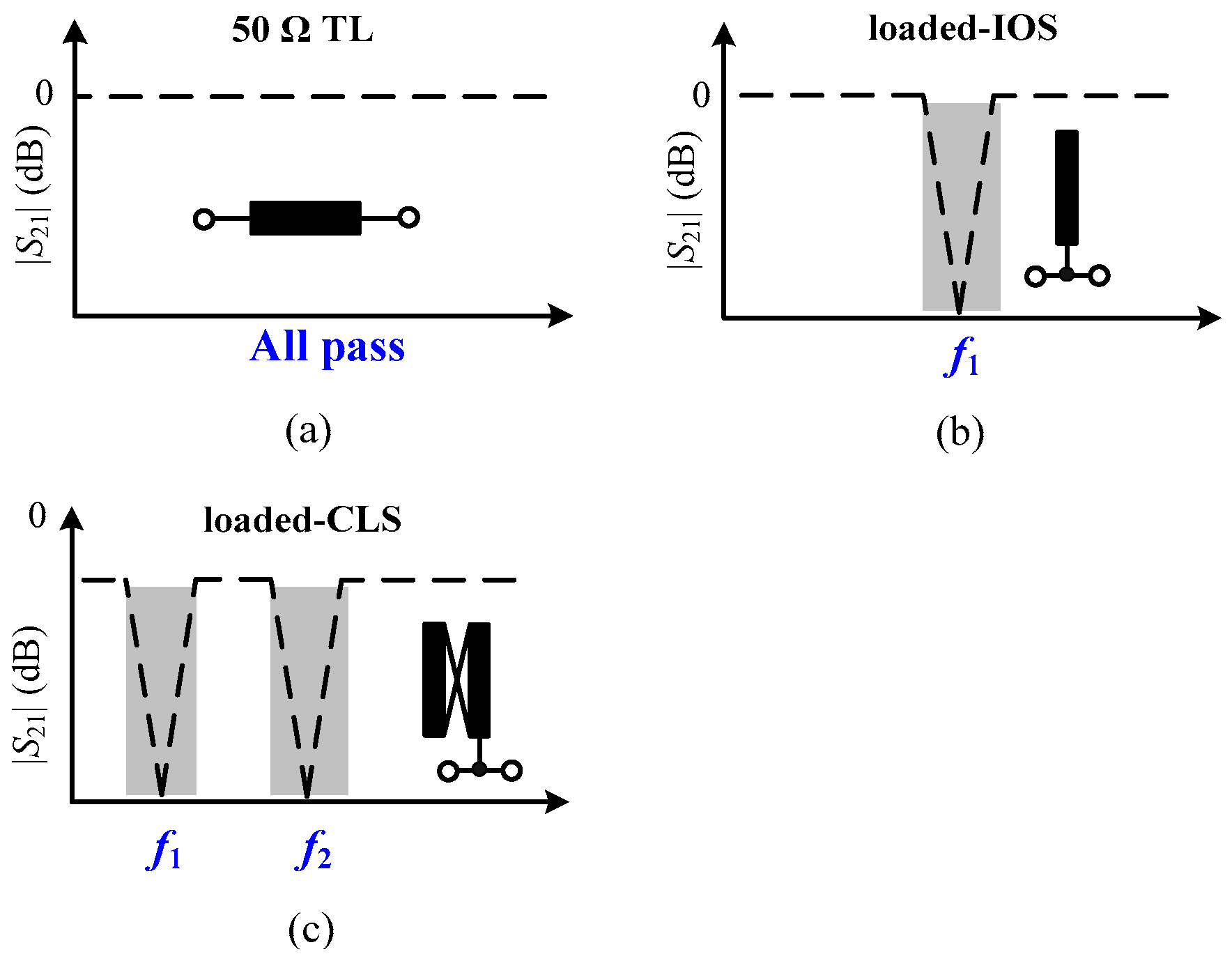
Figure 1 shows the flow diagram for the implementation scheme of a tri-band bandstop filter, and in Figure 1, TL means transmission line, IOS means impedance λ/4 open stub, and CLS means coupling line stub. In Figure 1a, the input and output feeds are directly connected to obtain a full passband response. In Figure 1b, an open branch is added. Due to the virtual ground effect introduced by the open branch, the signal cannot be directly transmitted from the input port to the output port, that is, the RF and microwave signals are all reflected and form a stopband. If the open branch is loaded in the middle of the input and output feeds, and the coupling branch is added to the open branch, the dual-frequency stopband response can be obtained, as shown in Figure 1c. The stopband center frequencies are expressed as f1 and f2.
According to the previous theoretical analysis, the tri-band multimode resonator based on symmetrically coupled branches proposed in this section is shown in Figure 2, which includes coupling branches (Zc1, k1, θ1) (Zc2, k2, θ2) and transmission branches (Z1, θ1) (Zn, θn). Z, k, and θ represent the characteristic impedance, coupling coefficient, and equivalent electrical length of the microstrip coupling line, respectively. In particular, the coupling branches marked by red dashed lines in Figure 2 are added to add a passband out-of-band transmission zero to each stopband.
Figure 3 shows the |S21| parameter response curve of the tri-band bandstop filter. As can be seen from the figure, when the coupling branches marked with the dotted red line are not loaded, each pair of out-of-band transmission zeros is one; when the coupled branches marked with the dotted red line in Figure 3 are loaded, each pair of out-of-band transmission zeros becomes two. In this way, the 10 dB bandwidth of the stopband can be adjusted more flexibly and the in-band characteristics of the stopband can be improved.
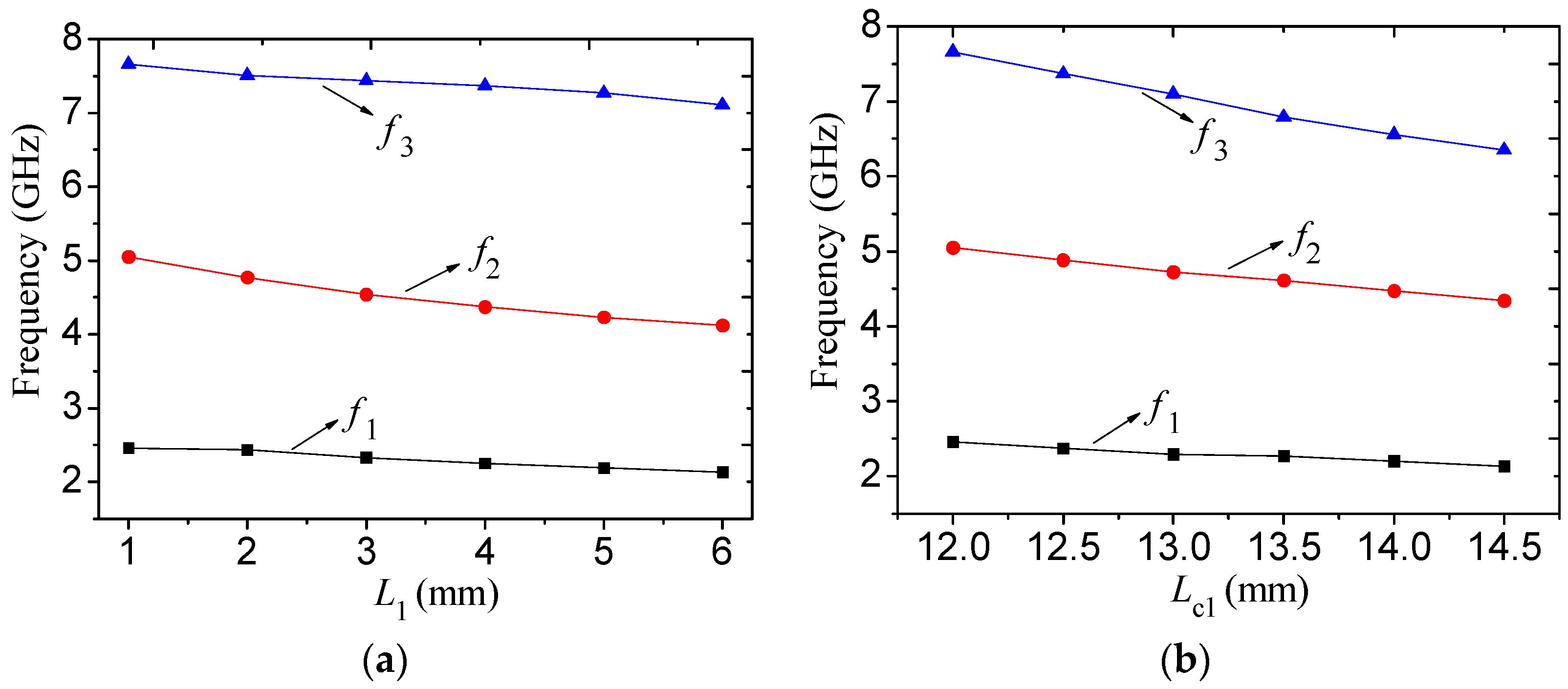
Here, f1 is used to represent the center frequency of the first stopband, and similarly, the center frequency of the second and third stopbands is represented by f2 and f3, respectively. In Figure 4, L1 represents the length of the transmission branch (Z1, θ1). We can adjust L1 to obtain the frequency curves shown in Figure 4a. It can be seen that with the increase in the parameter L1, the center frequencies f1, f2, and f3 of the first, second, and third stopbands all move to the low-frequency band, and the speed of f2 moving is significantly faster than that of f1 and f3. Similarly, in Figure 2, Lc1 represents the length of the coupling branch (Zc1, k1, θ1). By adjusting the Lc1 parameter, the frequency curves shown in Figure 4b can be obtained. It can be seen that with the increase in Lc1, the f1 basically remains unchanged, while the center frequencies f2 and f3 move to the low band, and the speed of f2 moving is obviously faster than that of f3. Therefore, the stopband center frequency can be adjusted by adjusting L1 and Lc1.
Similarly, as shown in Figure 5, the attenuation amplitude of the first stopband is represented by SA1, and the attenuation amplitude of the second and third stopbands is represented by SA2 and SA3, respectively. In Figure 2, Sc1 represents the coupling spacing of the coupling branch (Zc1, k1, θ1), that is, Sc1 is related to the coupling coefficient k1. If we adjust the parameter size of Sc1 so that Sc1 increases from 0.1 mm to 0.6 mm, the attenuation amplitude change curve shown in Figure 5a can be obtained. It can be seen that with the increase in the Sc1 parameter, the attenuation amplitude of the first stopband decreases, while the attenuation amplitudes of the second and third stopbands increase. Among them, the attenuation amplitude value of the first stopband SA1 decreases from 19 dB to 10 dB, the attenuation amplitude value of the second stopband SA2 increases from 38 dB to 46 dB, and the attenuation amplitude value of the third stopband SA3 increases from 45 dB to 59 dB. Similarly, in Figure 2, Sc2 represents the coupling spacing of the coupling branch (Zc2, k2, θ2), that is, Sc2 is related to the coupling coefficient k2. If we adjust the parameter size of Sc2 so that Sc2 increases from 0.1 mm to 0.6 mm, the attenuation amplitude change curve shown in Figure 5b can be obtained. It can be seen that the attenuation amplitudes of the three stopbands increase with the increase in the Sc2 parameter. Among them, the attenuation amplitude value of the first stopband SA1 increases from 19 dB to 30 dB, the attenuation amplitude value of the second stopband SA2 increases from 38 dB to 50 dB, and the attenuation amplitude value of the third stopband SA3 increases from 45 dB to 56 dB. It can be seen that by adjusting the coupling patch Sc1 and the coupling patch Sc2, the attenuation amplitudes of different stopbands of the tri-band bandstop filter also change correspondingly. Therefore, the stopband attenuation amplitudes can be flexibly controlled by adjusting the relevant parameters reasonably.
According to the equivalent transmission line model of the symmetric open-branch multimode resonator, the parameter values of the branches of the tri-band bandstop filter can be calculated using circuit simulation software, so as to obtain the initial size of the filter. These branches are rationally arranged, and the circuit design layout of the microstrip tri-band bandstop filter is obtained as shown in Figure 6.
Then, the filter circuit is modeled in 3D full-wave electromagnetic simulation software according to the design layout, and all of the branches are set to the initial size. Through simulation optimization, a filter circuit meeting the requirements is obtained. Finally, the optimized filter is fabricated and measured. The microstrip structure on the surface of the tri-band stopband filter circuit is made of a copper foil material, and the dielectric substrate is a Rogers TMM10 plate whose thickness h = 1 mm, relative dielectric constant εre = 9.2, and tanδ = 0.0022. The obtained parameters of the fabricated tri-band bandstop filter are as follows (unit: mm): L1 = 2.87, Lc1 = 16.36, Lc2 = 0.58, Ln = 6.80, Sc1 = 0.17, Sc2 = 1.39, Wn = 1.03. The final processed filter is shown in Figure 6. The figure does not specifically mark that the width of each branch W = 0.10 mm.
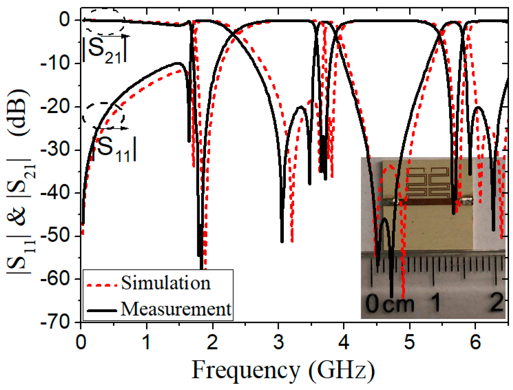
By measuring the filter circuit through the Agilent vector network analyzer, a comparison curve of the simulation and test data for the tri-band bandstop filter, as shown in Figure 7, can be obtained. It can be considered that the simulated and measured S-parameter amplitude–frequency characteristic curves are in good agreement, thus verifying that the design method proposed in this section is correct, effective, and feasible. The test results show that the three stopband center frequencies of the filter are 1.91 GHz, 3.59 GHz, and 5.71 GHz, respectively. The 10 dB stopband bandwidths are 52.35%, 13.37%, and 10.52%, respectively, and the corresponding stopband attenuation values are 49.95 dB, 29.45 dB, and 44.71 dB, respectively.
Through an analysis of the above results, it can be seen that the center frequency of each stopband based on the symmetric open-branch multimode resonator is controllable, and the attenuation amplitude between each stopband is easy to adjust. In the multi-frequency design process of this section, there are two ways to increase the number of stopbands. One is to increase the number of stopbands by increasing the number of symmetric open branches in the upper-branch filter circuit, and the other is to increase the number of stopbands by increasing the lower-branch filter circuit below the line of the monograph microstrip. These two methods can be used individually or in combination to realize the multi-frequency design of symmetric open-branch multimode resonators.
The quad-band multimode resonator proposed in this section is composed of the tri-band multimode resonator filter circuit discussed in the previous section cascaded with an open branch (Z2, θ2), and the remaining parts are as follows: the coupling branches (Zc1, k1, θ1) (Zc2, k2, θ2) and the transmission branches (Z1, θ1) (Zn, θn) remain unchanged, as shown in Figure 8.
Figure 9 shows the circuit design layout of the microstrip quad-band bandstop filter proposed in this section. Based on the design method of the multi-band bandstop filter proposed, the initial size of the quad-band bandstop filter can be easily calculated through circuit simulation software, and then the filter circuit can be modeled according to the design layout using three-dimensional full-wave electromagnetic simulation software. All of the components are set to the initial size, and a filter circuit meeting the requirements is obtained through simulation optimization.
Finally, the optimized filter is fabricated and measured. The surface microstrip structure of the quad-band bandstop filter circuit is made of a copper foil material, and the dielectric substrate is a Rogers TMM10 plate, whose thickness h = 1 mm, relative dielectric constant εre = 9.2, and tanδ = 0.0022. The obtained parameter sizes for the fabricated quad-band bandstop filter are as follows (unit: mm): L1 = 2.87, L2 = 1.51, Lc1 = 16.57, Lc2 = 0.58, Ln = 5.88, Sc1 = 0.17, Sc2 = 1.39, Wn = 1.03. The final processed filter is shown in Figure 10, and its circuit size is 0.11 λg × 0.10 λg, where λg is the guided wavelength of the first stopband, and the corresponding stopband center frequency is 1.81 GHz. The branch width W = 0.10 mm, which is not specifically marked in the figure.
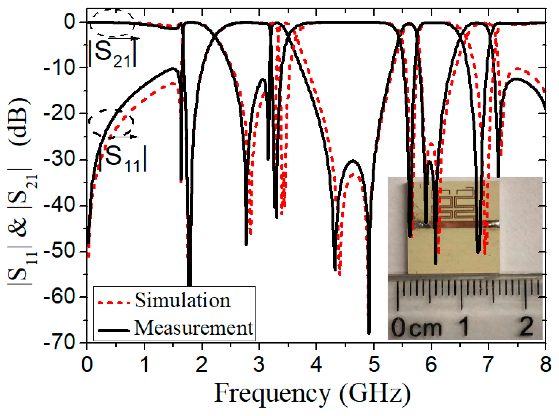
By measuring the filter circuit through the Agilent vector network analyzer, the quad-band bandstop filter simulation and test data comparison curve shown in Figure 10 can be obtained. It can be considered that the simulated and measured S-parameter amplitude–frequency characteristic curves are in good agreement, thus verifying that the design method proposed in this section is correct, effective, and feasible. Through testing, it can be observed that the four stopband center frequencies of the filter are 1.81 GHz, 3.41 GHz, 5.69 GHz, and 6.84 GHz, respectively. The 10 dB stopband bandwidths are 46.41%, 15.84%, 8.79%, and 11.11%, respectively, and the corresponding stopband attenuation values are 52.64 dB, 33.72 dB, 46.37 dB, and 49.73 dB, respectively.
Through the theoretical analysis above, it can be concluded that the design method of the multiband stop filter obtained in this section increases the number of stopbands by increasing the number of symmetric open branches on the upper-branch filter circuit structure, or by adding a lower-branch filter unit. For example, the quad-band bandstop filter proposed in this section increases the number of stopbands by increasing the number of symmetrical open branches on the upper-branch filter circuit structure.
The quint-band bandstop filter proposed in this section will increase the number of stopbands by adding a lower-branch filter unit. As shown in Figure 11, the quint-band multimode resonator proposed in this section is based on symmetric open branches. It consists of upper- and lower-branch filtering circuits, where the upper branch is consistent with that in the filter circuit of the quad-band multimode resonator in the previous section, the coupling branches (Zc1, k1, θ1) (Zc2, k2, θ2), and the transmission branches (Z1, θ1) (Zn, θn). The open branch (Z2, θ2) remains unchanged, and the lower-branch filter circuit contains the coupling branches (Zc3, k3, θ3) (Zc4, k4, θ4) and the transmission branch (Z3, θ3).
Figure 12 shows the circuit design layout of the quint-band bandstop filter proposed in this section. Based on the multi-band bandstop filter design method proposed in this section, the initial size of the quint-band bandstop filter can be easily calculated through circuit simulation software, and then the filter circuit is modeled according to the design layout using three-dimensional full-wave electromagnetic simulation software. All of the components are set to the initial size, and a filter circuit meeting the requirements is obtained through simulation optimization. Finally, the optimized filter is processed and measured. The surface microstrip structure of the quint-band bandstop filter circuit is made of a copper foil material, and the dielectric substrate is a Rogers TMM10 plate, whose thickness h = 1 mm, relative dielectric constant εre = 9.2, and tanδ = 0.0022. The parameter sizes of the quint-band bandstop filter obtained through this process are as follows (unit: mm): L1 = 2.87, L2 = 1.51, L3 = 5.18, Lc1 = 16.57, Lc2 = 0.58, Lc3 = 10.88, Lc4 = 2.66, Ln = 6.80, Sc1 = 0.17, Sc2 = 1.39, Sc3 = 0.15, Sc4 = 3.05, Wn = 1.03. The final processed filter is shown in Figure 12. The branch width W = 0.10 mm, which is not specifically marked in the figure.
The filter circuit is measured using the Agilent vector network analyzer, and a comparison curve of the simulation and test data for the quint-band bandstop filter, as shown in Figure 13, can be obtained. It can be considered that the simulated and measured S-parameter amplitude–frequency characteristic curves are in good agreement. The test results show that the central frequencies of the five stopbands of the filter are 1.83 GHz, 2.52 GHz, 3.50 GHz, 4.19 GHz, and 5.72 GHz, respectively. The 10 dB stopband bandwidths are 21.86%, 31.87%, 9.71%, 17.90%, and 7.52%, respectively. The corresponding stopband attenuation values are 45.06 dB, 43.91 dB, 24.53 dB, 32.86 dB, and 34.75 dB, respectively.
Through the above analyses and research, the design and exploration of tri-band to quint-band bandstop filters are realized, and their simulated and measured S-parameter amplitude–frequency characteristic curves are in good agreement, indicating that the design method proposed in this section is correct and effective, and the design scheme is feasible. Therefore, the design method is summarized as follows:
- (1)
- According to the number of stopbands of the filter being designed and the location of the center frequency of each stopband, determine whether to use a single-branch filter structure or a double-branch filter structure to achieve the number of stopbands. Considering the circuit topology characteristics, it is recommended that if there are four stopbands or less, the single-branch filter structure can meet the needs of the passband; if there are five stopbands or more, it is recommended to add a lower-branch filter structure.
- (2)
- If it is a single-branch filter structure, the number of open-circuit branches to be loaded is determined according to the number of stopbands, and the equivalent impedance and equivalent electrical length of each branch are derived according to the stopband center frequency. The initial physical size of each symmetrical open-circuit branch is calculated using full-wave analysis simulation software.
- (3)
- If it is a double-branch filter structure, determine the number of open branches to be loaded according to the number of stopbands, take into account the circuit topology characteristics, reasonably arrange the number of open branches to be loaded by each branch filter structure, and then determine the initial physical size of the symmetric open branches of each branch filter structure as described in the previous step.
- (4)
- Whether it is a single-branch filter structure or a double-branch filter structure, after connecting the obtained filter structure with the input and output feeders, some changes will occur in both the stopband center frequency position and the electrical performance inside and outside the band. Therefore, it is also necessary to conduct modeling in three-dimensional full-wave electromagnetic simulation software, and then adjust the circuit parameters. The simulation curve of the S-parameter amplitude–frequency characteristics is then obtained. Finally, the multi-band bandstop filter is obtained through fabrication and measured.
3. Results and Comparisons
According to the design method for multi-band bandstop filters summarized above, this section will complete the experimental study of the sext-band bandstop filter.
- First of all, the number of target stopbands designed according to the needs of the filter is six, and the central frequency of each stopband is 1.80 GHz (GSM), 2.45 GHz (WLAN and WIFI), 3.50 GHz (WiMax), 4.00 GHz (digital microwave relay communication system), 5.20 GHz (WLAN), and 5.80 GHz (WLAN). Three stopbands each are realized through the upper-branch filter structure and the lower-branch filter structure, and finally six stopbands are obtained. The sext-band multimode resonator based on symmetrically coupled branches proposed in this section is composed of an open-circuit branch (Z4, θ4) cascaded to the lower branch of the quint-band multimode resonator in the previous section, and the remaining parts are as follows: the coupling branches of the upper branch (Zc1, k1, θ1) (Zc2, k2, θ2), the transmission branches (Z1, θ1) (Zn, θn), the open branch (Z2, θ2), the coupling branches of the lower branch (Zc3, k3, θ3) (Zc4, k4, θ4), and the transmission branch (Z3, θ3) all remain unchanged, as shown in Figure 14.
- Then, according to the determined stopband number and stopband center frequency position, the equivalent impedance and equivalent electrical length of each limb are derived, and then the initial physical size of the sext-band bandstop filter is calculated using circuit simulation software. The circuit design layout of the sext-band bandstop filter, as shown in Figure 15, is obtained according to the reasonable layout of each branch.
- Finally, after each branch is coupled with the input and output feeds, some changes will occur in both the stopband center frequency position and the electrical performance inside and outside the band. Then, the filter circuit can be modeled according to the design layout in the three-dimensional full-wave electromagnetic simulation software, and all branches are set to the initial size. Finally, the optimized filter is fabricated and measured.
The surface microstrip structure of the sext-band bandstop filter circuit is made of a copper foil material, and the dielectric substrate is a Rogers TMM10 plate, whose thickness h = 1 mm, relative dielectric constant εre = 9.2, and tanδ = 0.0022. The parameter sizes of the sext-band bandstop filter obtained through this processing are as follows (unit: mm): L1 = 2.87, L2 = 1.51, L3 = 5.18, L4 = 4.92, Lc1 = 16.57, Lc2 = 0.58, Lc3 = 10.88, Lc4 = 2.66, Ln = 6.80, Sc1 = 0.17, Sc2 = 1.39, Sc3 = 0.15, Sc4 = 3.05, Wn = 1.03. W = 0.10 mm for each branch’s width, which is not specifically marked in the diagram of the final processed filter shown in Figure 15. Its circuit size is 0.21 λg × 0.11 λg, where λg is the guided wavelength of the first stopband, and the corresponding stopband center frequency is 1.83 GHz.
By measuring the filter circuit through the Agilent vector network analyzer, the comparison curve of the simulation and test data for the sext-band bandstop filter, as shown in Figure 16, can be obtained. As can be seen from Figure 16, there is some modest variation between the simulated results and the measured results due to the inhomogeneity of the substrate’s dielectric constants, manufacturing tolerance, and SMA connections. It can be considered that the simulated and measured S-parameter amplitude–frequency characteristic curves are in good agreement. The six stopband center frequencies of the filter are 1.83 GHz, 2.43 GHz, 3.59 GHz, 4.12 GHz, 5.19 GHz, and 5.77 GHz, respectively. The 10 dB stopband bandwidths are 21.82%, 32.92%, 8.91%, and 13.63%, respectively. The corresponding stopband attenuation values of 6.92% and 5.86% were 47.63 dB, 43.69 dB, 27.14 dB, 26.59 dB, 33.19 dB, and 38.87 dB, respectively.
4. Conclusions
In this paper, the multi-frequency bandstop filters implemented by loading open branches onto multimode resonators are not only more compact in the size of their structures, but they also have higher levels of stopband attenuation between the stopbands. The proposed mixed electric and magnetic coupling resonators, including the multimode resonator based on symmetrical open-circuit branches, include upper- and lower-branch filter circuits. Through this design, the center frequencies of the stopbands can be flexibly and autonomously adjusted, and the measured results agree well with the simulated ones. Furthermore, the proposed filters have excellent characteristics, such as miniature dimensions and abrupt roll-off skirts.
Author Contributions
Conceptualization, J.L. and J.Z.; methodology, J.L.; validation, J.L., J.Z. and S.G.; formal analysis, J.L.; data curation, S.G.; writing—original draft preparation, J.L.; writing—review and editing, J.L.; supervision, J.Z.; funding acquisition, S.G. All authors have read and agreed to the published version of the manuscript.
Funding
This research was funded by Guangxi Key Laboratory of Wireless Wideband Communication and Signal Processing, grant number GXKL06220205, and the Multi-physics field coupling simulation modeling of laser-irradiated materials, Institute of Fluid Physics, Chinese Academy of Engineering Physics.
Data Availability Statement
Data are available on request from the authors.
Conflicts of Interest
Author Jinhao Zhang was employed by the company Chongqing Research Institute Co., Ltd. The remaining authors declare that the research was conducted in the absence of any commercial or financial relationships that could be construed as a potential conflict of interest.
References
- Gao, L.; Zhang, X.Y.; Xue, Q. Compact tri-band bandpass filter using novel eight-mode resonator for 5G WiFi application. IEEE Microw. Wirel. Compon. Lett. 2015, 25, 660–662. [Google Scholar] [CrossRef]
- Xu, J.; Miao, C.; Cui, L.; Ji, Y.-X.; Wu, W. Compact high isolation quad-band bandpass filter using quad-mode resonator. Electron. Lett. 2012, 48, 28–30. [Google Scholar] [CrossRef]
- Wu, H.W.; Yang, R.Y. A new quad-band bandpass filter using asymmetric stepped impedance resonators. IEEE Microw. Wirel. Compon. Lett. 2011, 21, 203–205. [Google Scholar] [CrossRef]
- Liu, L.; Jin, R.H.; Zhang, C.; Geng, J.-P.; Liang, X.-L. A novel dual-band bnadstop filter based on parallel stub-loaded resonator. Microw. Opt. Technol. Lett. 2016, 58, 1268–1271. [Google Scholar] [CrossRef]
- Faisal, M.; Khalid, S.; Rehman, M.U.; Rehman, M.A. Synthesis and design of highly selective multi-mode dual-band bandstop filter. IEEE Access 2021, 9, 43316–43323. [Google Scholar] [CrossRef]
- Tang, M.C.; Wen, Z.; Wang, H.; Li, M.; Ziolkowski, R.W. Compact, frequency-reconfigurable filtenna with sharply defined wideband and continuously tunable narrowband states. IEEE Trans. Antennas Propag. 2017, 65, 5026–5034. [Google Scholar] [CrossRef]
- Qiu, L.L.; Zhu, L. Wideband bandstop filters based on wideband 180° phase shifters. IET Microw. Antennas Propag. 2020, 14, 1662–1670. [Google Scholar] [CrossRef]
- Zuo, X.; Qin, L. A novel approach to design wideband bandstop filter with wide upper bandpass bandwidth. AEU-Int. J. Electron. Commun. 2021, 138, 153897. [Google Scholar] [CrossRef]
- Zhu, Y.; Dong, Y. Novel dual-band bandpass-to-bandstop filter using shunt PIN switches loaded on the transmission line. In Proceedings of the 2020 IEEE/MTT-S International Microwave Symposium (IMS), Los Angeles, CA, USA, 4–6 August 2020; IEEE: New York, NY, USA; pp. 924–927. [Google Scholar]
- Yang, H.; Zhang, D.; Zhang, J.; Wang, X.; Lv, D.; Zhang, Y.; Zhou, D. A highly selective tri-band bandpass-to-bandstop filter with the third band independently tunable. Eng. Rep. 2022, 4, e12463. [Google Scholar] [CrossRef]
- Chen, W.Y.; Weng, M.H.; Chang, S.J. A new tri-band bandpass filter based on stub-loaded step-impedance resonator. IEEE Microw. Wirel. Compon. Lett. 2012, 22, 179–181. [Google Scholar] [CrossRef]
- Ning, H.; Wang, J.; Xiong, Q.; Mao, L. Design of planar dual and triple narrow-band bandstop filters with independently controlled stopbands and improved spurious response. Progr. Electromagn. Res. 2012, 131, 259–274. [Google Scholar] [CrossRef]
- Min, X.; Zhang, H. Compact triple-band bandstop filter using folded, symmetric stepped-impedance resonators. AEU-Int. J. Electron. Commun. 2017, 77, 105–111. [Google Scholar] [CrossRef]
- Luo, J.; Zhao, G.; Sheng, Z.; Gao, S. A novel miniaturized sext-band bandstop filter based on tree-shaped branches loaded asymmetric multimode resonators. Electron. Lett. 2023, 59, e12801. [Google Scholar] [CrossRef]
- Chin, K.S.; Yeh, J.H.; Chao, S.H. Compact dual-band bandstop filters using stepped-impedance resonators. IEEE Microw. Wirel. Compon. Lett. 2007, 17, 849–851. [Google Scholar] [CrossRef]
- Zhang, X.Y.; Huang, X.; Zhang, H.L.; Hu, B.-J. Novel dual-band bandstop filter with controllable stopband frequencies. Microw. Opt. Technol. Lett. 2012, 54, 1203–1206. [Google Scholar] [CrossRef]
- Chen, F.C.; Qiu, J.M.; Chu, Q.X. Dual-band bandstop filter using stub-loaded resonators with sharp rejection characteristic. Electron. Lett. 2013, 49, 351–353. [Google Scholar] [CrossRef]
- Wang, W.; Liao, M.; Wu, Y.; Liu, Y. Small-size high-selectivity bandstop filter with coupled-line stubs for dual-band applications. Electron. Lett. 2014, 50, 286–288. [Google Scholar] [CrossRef]
- Janković, N.; Geschke, R.; Crnojević-Bengin, V. Compact tri-band bandpass and bandstop filters based on Hilbert-fork resonators. IEEE Microw. Wirel. Compon. Lett. 2013, 23, 282–284. [Google Scholar] [CrossRef]
Figure 1.
The realization process for a bandstop filter. (a) Full passband response; (b) single stopband; (c) double stopband.
Figure 1.
The realization process for a bandstop filter. (a) Full passband response; (b) single stopband; (c) double stopband.

Figure 2.
The tri-band equivalent model.

Figure 3.
|S21| parameter response curve of a tri-band BSF.

Figure 4.
Frequency curves: (a) L1; (b) L2.

Figure 5.
Different attenuation amplitudes SA: (a) Sc1; (b) Sc2.

Figure 6.
Tri-band bandstop filter design layout.

Figure 7.
The |S11| and |S21| of the tri-band BSF.

Figure 8.
The quad-band equivalent model.

Figure 9.
Quad-band bandstop filter design layout.

Figure 10.
The |S11| and |S21| of the quad-band BSF.

Figure 11.
The quint-band equivalent model.

Figure 12.
Quint-band bandstop filter design layout.

Figure 13.
The |S11| and |S21| of the quint-band BSF.

Figure 14.
The sext-band equivalent model.

Figure 15.
The suggested sext-band BSF structure.

Figure 16.
The |S11| and |S21| of the sext-band BSF.

Disclaimer/Publisher’s Note: The statements, opinions and data contained in all publications are solely those of the individual author(s) and contributor(s) and not of MDPI and/or the editor(s). MDPI and/or the editor(s) disclaim responsibility for any injury to people or property resulting from any ideas, methods, instructions or products referred to in the content. |
© 2024 by the authors. Licensee MDPI, Basel, Switzerland. This article is an open access article distributed under the terms and conditions of the Creative Commons Attribution (CC BY) license (https://creativecommons.org/licenses/by/4.0/).
Share and Cite
MDPI and ACS Style
Luo, J.; Zhang, J.; Gao, S. Design of Multi-Band Bandstop Filters Based on Mixed Electric and Magnetic Coupling Resonators. Electronics 2024, 13, 1552. https://doi.org/10.3390/electronics13081552
AMA Style
Luo J, Zhang J, Gao S. Design of Multi-Band Bandstop Filters Based on Mixed Electric and Magnetic Coupling Resonators. Electronics. 2024; 13(8):1552. https://doi.org/10.3390/electronics13081552
Chicago/Turabian StyleLuo, Jie, Jinhao Zhang, and Shanshan Gao. 2024. "Design of Multi-Band Bandstop Filters Based on Mixed Electric and Magnetic Coupling Resonators" Electronics 13, no. 8: 1552. https://doi.org/10.3390/electronics13081552
Note that from the first issue of 2016, this journal uses article numbers instead of page numbers. See further details here.