
High Accuracy Localization Scheme Using 1-Bit Side Information: Achievability from a GDoP Perspective


1
Department of Electronic Engineering, Hanyang University, Seoul 04763, Republic of Korea
2
School of Electronic Engineering, Kyonggi University, Suwon 16227, Republic of Korea
3
Train Control and Communications Research Department, Korea Railroad Research Institute, Uiwang 16105, Republic of Korea
*
Authors to whom correspondence should be addressed.
†
This work was done when S. Park was with Kyonggi University.
Electronics 2024, 13(8), 1574; https://doi.org/10.3390/electronics13081574
Submission received: 31 March 2024
/
Revised: 15 April 2024
/
Accepted: 17 April 2024
/
Published: 20 April 2024
(This article belongs to the Special Issue 5G and 6G Wireless Systems: Challenges, Insights, and Opportunities)
Abstract
:In this paper, we provide a novel methodology for high-precision positioning that utilizes 1-bit additional information, which applies to various positioning techniques. The proposed approach leverages binary information to indicate if a user is within a specified space of interest and refines the estimated location information outside this area. By matching the estimated locations outside the area of interest with the valid location information within, this methodology corrects the positional data obtained through any arbitrary positioning technique, aligning the estimated positions with the intended spatial boundaries. Performance analysis metrics, such as Average Positioning Error (APE) and Cumulative Distribution Function for positioning coverage, were employed to assess the effectiveness of the proposed methods. Numerical simulations demonstrate how the proposed method enhances the averaged positioning accuracy, significantly outperforming the conventional time of arrival method. Furthermore, the proposed positioning correction methodology demonstrates validated feasibility applicable to an arbitrary existing positioning method.
1. Introduction
The rapid advancements in mobile communication have driven the emergence of diverse convergence services [1]. These services, which utilize location information, are finding commercial applications in areas such as autonomous driving and smart factories. Location-based services rely on multiple mobile communication technologies, including beacons, wireless fidelity (Wi-Fi), Ultra-WideBand (UWB), and 5G. Owing to the growing significance of location information, researchers have extensively investigated positioning technologies using various wireless communication methods [2,3,4,5,6,7,8].
Along with the technical evolution of wireless communications, the 3rd Generation Partnership Project (3GPP) has been pivotal in standardizing location positioning technologies across various cellular network generations [9], with significant advancements observed in recent releases, particularly Release 16 (Rel-16) [10] and Release 17 (Rel-17) [11]. Specifically, Rel-16 introduced multiple enhancements to location services in the 5G context. This release saw the implementation of time-based positioning methods, such as multi-round-trip time (RTT), and the downlink and uplink Time Difference of Arrival (TDoA) for standalone 5G New Radio (NR) deployments. Furthermore, it utilized angle of arrival (AoA) and angle of departure (AoD) based positioning measurements. These methods combine timing and angle measurements to achieve a higher positioning accuracy, essential for applications in sectors like automotive and Industrial Internet of Things (IIoT). Moving to Rel-17, there is a further refinement in the positioning accuracy and the introduction of integrity and reliability measures. Specifically, Rel-17 targeted the indoor location accuracy to 20–30 cm for certain use cases, such as factory automation, which is critical for Industry 4.0 applications. This release also aimed at reducing the latency in positioning to support time-critical applications such as remote-control operations. In addition to the accuracy and latency improvements, Rel-17 emphasized the integrity protection of location information. This involves ensuring the reliability of the positioning data, particularly for safety-critical applications where incorrect data could have severe implications. The release also defined key performance indicators for the reliability and integrity of the measurement reports, limited primarily to Global Navigation Satellite System (GNSS) procedures.
Location information is commonly acquired using Time of Arrival (ToA) or AoA techniques. ToA-based positioning measures the signal arrival time to estimate the position. Typically, a minimum of three anchor points is required to obtain two-dimensional location information. The difference in the signal arrival times between these anchor points aids in determining the location of the terminal [12,13,14,15,16,17]. In contrast, AoA-based positioning calculates the user terminal’s position by measuring the angles between the terminal and anchor points. At least two anchors are required to determine the 2D location information. The terminal’s location is determined by measuring the angle between the target and reference nodes in a 2D space [18,19].
Numerous studies have explored various perspectives to improve the average accuracy of fundamental positioning techniques. External environmental factors, such as multipath and obstacles, introduce errors in the obtained location information, prompting researchers to enhance the positioning accuracy [20]. For example, some methods use a variable or a correct term instead of a square term to effectively reduce Non-Line-of-Sight (NLoS) errors along the actual axis. Other approaches consider angular anchor placement and employ a mathematical analysis or grid search technology-based algorithms to enhance the accuracy by incorporating ToA and AoA in a geometric-based single-bounce circular model [21]. Additional methods reduce the errors by applying new formulas, such as the Weighted Centroid Localization (WCL) algorithm with cross-thresholds, to enhance the location estimation accuracy [22]. Additionally, the proposed two-stage Time of Signal Estimation (TSE) algorithms update the temporary estimation results using only addition, multiplication, and square root operations [23]. Researchers have also explored the use of neural networks, such as Artificial Neural Networks (ANN) and Radial Basis Function (RBF) neural networks, to address measurement errors [24], offering alternative techniques for improving positioning accuracy. Recently, there have been studies to enhance not only the positioning accuracy but also the connectivity in conjunction with connection information, a low complexity approach with a low-resolution analog to digital converter, and machine learning [25,26,27].
The main contribution of this study is to provide a novel methodology that enhances positioning accuracy by incorporating additional 1-bit information, which indicates if the estimated location is within a predefined space of interest. Specifically, our main contribution in comparison with existing related works can be elaborated as follows:
- –
- Combination of Channel Impulse Response (CIR) based fingerprinting positioning and iterative-ToA real-time positioning methods
- –
- Non Line of Sight (NLoS) mitigation algorithms were used to improve incorrect location estimates corrupted by NLoS errors and proposed a cellular-based location tracking system.
- –
- Analysis of the optimal geometry for the two-dimensional ToA localization configurations based on minimizing the area of estimation confidence region
- –
- A new grid search-based technique was proposed to solve the constraint, nonlinear, underdetermined Equations for wireless location in NLoS environments
- –
- A novel algorithm for reducing error called TSE computing estimates and updating the location vector
- –
- ToA method with low computational complexity
- Machine learning-based localization method [24]
- –
- Application of ANN and RBF neural network to localization methods with ToA measurements
- Our work
- –
- Proposal of position correction method which applies to existing artibrary positioning schemes.
Since our proposed scheme is a kind of position correction scheme that serves to correct the position value into the space of interest when the position value is estimated out of the space of interest, it may be applied to any positioning schemes such as ToA, TDoA, AoA, fingerprint-based positioning, and so on In this case, the 1-bit information refers to the amount of information indicating whether the user using the location service is in the space of interest. More specifically, it means having a value of 1 when it is in the space of interest and 0 when it is not in the space of interest. Therefore, it is possible to correct the positioning value obtained through the existing positioning technique through the information on whether it is in the space of interest, which is the main issue of this paper. This 1-bit information corrects the obtained location, improving measurement accuracy. The proposed methodology effectively leverages supplementary 1-bit data to refine and enhance positioning precision.
The paper is organized as follows: Section 2 presents the positioning system model, including tailored anchor placement strategies for positioning within a predefined space of interest. Section 3 introduces Geometric Dilution of Precision (GDoP) as a fundamental metric for assessing positioning accuracy. Section 4 presents novel methodologies for effectively correcting the acquired location information. Section 5 analyzes the simulation results, focusing on the average positioning accuracy and the location information correction method. Finally, Section 6 concludes the paper by summarizing the key findings and contributions.
2. System Model
Figure 1 illustrates the spatial environment designed to accurately estimate the user’s 2D location information . The positioning setup involves evenly spacing k anchors at each corner, resulting in a total of anchors (where k is a positive integer). Each anchor is assigned position information denoted as . It is assumed that the user has knowledge of these anchor positions.
This study introduces a correction method that utilizes ToA-based 2D positioning to enhance positioning accuracy. The ToA-based 2D location information, represented as , is defined as follows:
where
and represents the inverse matrix of .
3. Preliminaries on GDoP
The GDoP is a theoretical indicator that correlates measurement errors with errors in the position estimation, particularly within the domain of type-position estimation [23]. It serves as a valuable tool for understanding the linear position estimators’ limitations in the positioning performance.
The term denotes the root mean square (RMS) value of the positioning error, whereas represents the RMS value of the measured value error in (5). The GDoP is calculated based on this equation, with a lower GDoP value indicating a more accurate position measurement. Therefore, it is crucial to utilize positioning anchors with lower GDoP values to enhance the accuracy. The specific calculation outlined in this study was employed to determine the GDoP of the location estimation technique.
The variable represents the distance between the anchor and the user’s exact location in (6). The term is employed in the calculation of GDoP, where represents the trace of matrix , which is the sum of its main diagonal components. As the distance between the anchors and the user’s location increases, the GDoP also increases. Moreover, increasing the number of anchor nodes decreases the GDoP. This formula demonstrates the impact of measurement errors on location accuracy, emphasizing how the geometric arrangement of the anchor nodes affects the GDoP. Figure 2 illustrates the uniform distribution of the anchors around the terminal. The GDoP at the center point can be calculated using the formulas outlined in [23,33].
Here, N represents the number of anchors, and as N increases, the positioning accuracy at the center point also improves proportionally to .
4. ToA-Based Positioning Technology Using Additional Information
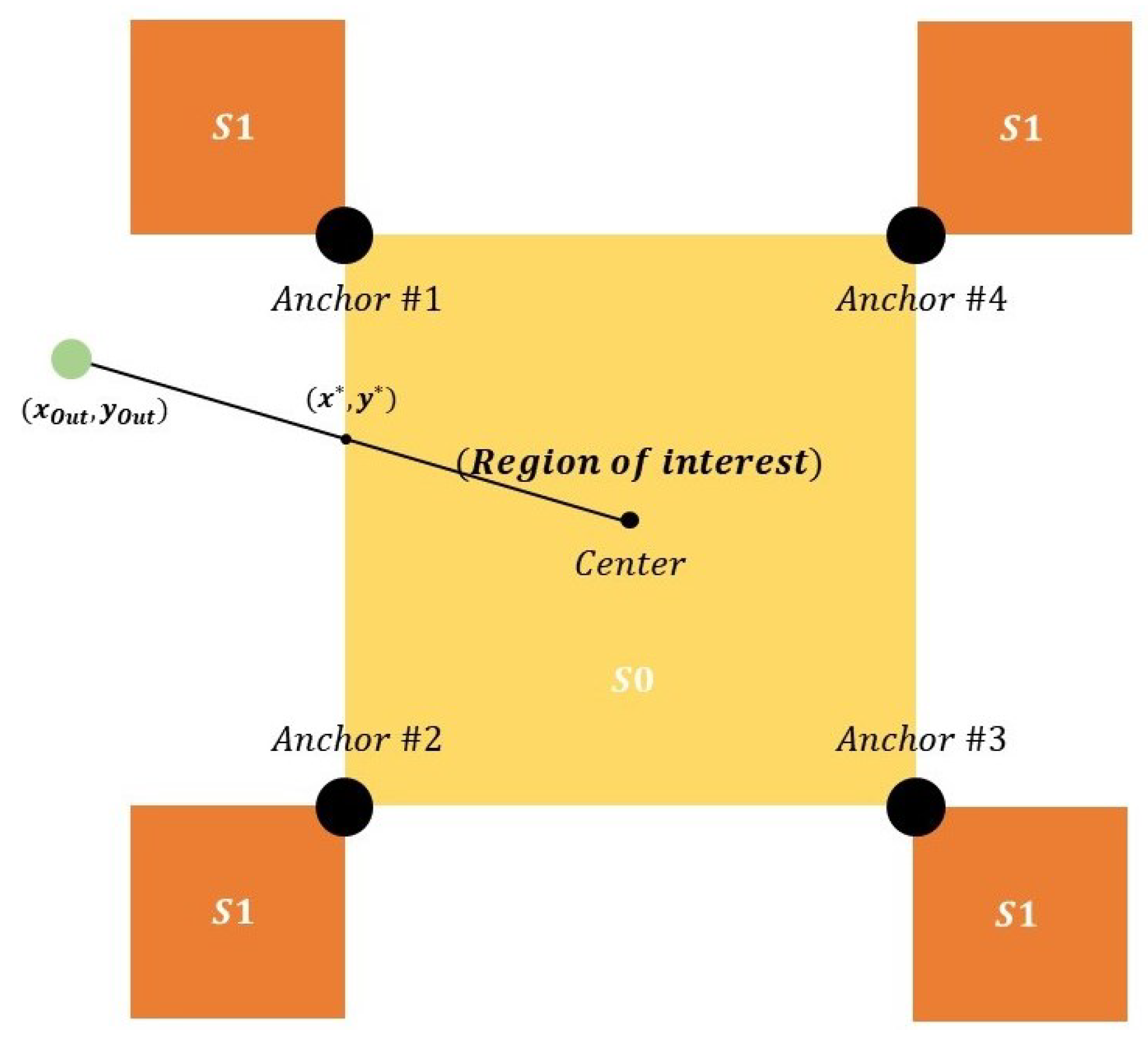
The proposed method aims to enhance the location accuracy by adjusting the estimated location information using 1-bit data that indicate the user presence within a predetermined space. Correcting the estimated position value when it exceeds the specified space is a logical step, as this reduces the measurement errors. Analyzing the measurement results separately minimizes errors and enhances the location estimation accuracy. To achieve this objective, the given space was divided into S0, S1, and S2. These divisions rectify the location estimation information for each specific area. S0 denotes the user space, S1 represents the space located at the edge beyond the user space, and S2 corresponds to the space adjacent to the user space. Consequently, the position estimation value is corrected based on the following facts pertaining to each area:
- Owing to the absence of external positioning points in space S0, the position is estimated using only the general ToA. In space S1, located outside the user space, the ToA value is used for measurement, and an additional method is employed to adjust the positioning point within this space;
- Two methods are available for correcting points in the S1 space. The first method involves using the anchor point located at the closest corner of the user space. The second method involves correcting points outside the space by considering the intersection formed by the center point of the user space and the anchors, with straight lines passing through them;
- Two methods are available for correcting points in the S2 space. The first method corrects the external point by lowering it perpendicularly to the user space formed by the anchor, while the second method corrects the external point using the intersection of the user space and the straight line passing through the center point of the user space. Table 1 provides an overview of the correction methods employed for each area in relation to the position estimation values.
Note: This study employed ToA for location estimation, but any technique can be used for the proposed schemes #1–3. Figure 3, Figure 4 and Figure 5 depicts each three schemes.
4.1. Scheme #1
The first method corrects the outer point in the S1 area by using the close anchor coordinates of each corner. Additionally, it corrects the outer point located in the S2 area by vertically lowering it to the nearest side of the user space and replacing it with the point . This method, which is simpler compared to Scheme #1, aligns the external point with a point in the user space, effectively reducing the overall positioning error.
4.2. Scheme #2
The second method corrects the outer point in S1 by utilizing the close anchor coordinates of each corner. Additionally, it corrects the outer point in the S2 area by finding the intersection of the user space and the straight line passing through both the user space’s center point and the user space’s side. The intersection is determined using the following method:
In this case, the center point is set at the origin (0, 0). If we represent the measurement coordinates as , and combine (10) and (11) into a single matrix, the expression becomes as follows:
Accordingly, the modified can be obtained using (15).
4.3. Scheme #3
The third method corrects both spaces S1 and S2 at the intersection of the external point and the straight line passing through the center point of the user space. The formula used is depicted in Scheme #2.
This study analyzes schemes #1 to #3 from the GDoP perspective. Establishing a regular polygon around the center is preferable for accurate position estimation at the center point (0, 0) regarding GDoP. As the number of anchors increases, the spatial arrangement resembles circles, leading to a decrease in location accuracy in the following order: Scheme #3, Scheme #2, and Scheme #1. Therefore, an effective approach is to correct the points outside the designated space by connecting the corresponding corner’s origin and intersection with a straight line.
5. Performance Analysis
5.1. Simulation Environment
In this location estimation simulation, we evaluated the effectiveness of the proposed correction methods applied to the basic linear location measurement methods (ToA and AoA). To incorporate measurement errors, we introduced noise with varying variances drawn from a normal distribution [23]. A lower variance noise indicates a greater measurement precision, while a higher variance noise corresponds to a reduced accuracy. We calculate using the GDoP to assess the theoretical limitations of the linear position estimation method, ToA. This calculation determines the maximum expected positioning error and is a simulation performance metric. The positioning error from each simulation is converted into . The simulations are repeated times to ensure statistically significant results. Initially, we randomly generated terminal coordinates within a user range for the positioning simulation.
5.2. Simulation Result
5.2.1. Average Positioning Error Perspective
The Average Positioning Error (APE) compares the RMS values with the estimated position coordinates obtained through the location estimation for randomly generated 2D position coordinates within a space. In addition, we express the RMS value of the position estimation error based on GDoP using the following equation:
The simulation values were obtained for each scheme, and the GDoP values were calculated using (9) for the proposed method and the general ToA method with uniformly distributed anchors. Additionally, the corresponding values were calculated and presented alongside the results.
Analyzing Figure 6 and Figure 7, it is evident that the noise value remains small, except for , resulting in minimal differences among the three methods. The overall accuracy follows this improvement order: general ToA, GDoP-based error estimation with general ToA, Scheme #1, Scheme #2, and Scheme #3. Notably, employing eight anchors instead of four reduces the error in all five cases.
Table 2 and Table 3 show the difference between the APE value obtained through the GDoP value and the APE of each method. Therefore, the three newly proposed methods have better accuracy than the obtained positioning error, and the performance is good in the order of Scheme #3, Scheme #2, and Scheme #1.
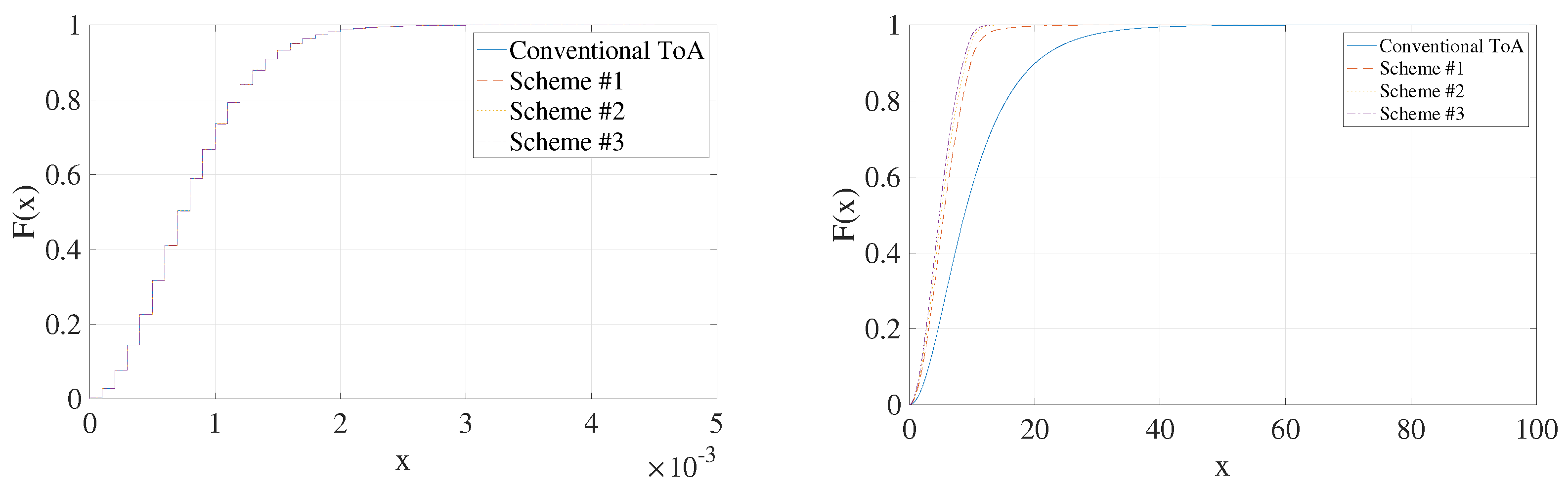
5.2.2. CDF Perspective of Mean Positioning Error
The Cumulative Distribution Function (CDF) of the APE used to generate the following Figure 8 and Figure 9. Figure 8 illustrates the increasing order of the x-axis error value as the probability value approaches one for four anchors. The order of increasing magnitude is as follows: Scheme #3, Scheme #2, Scheme #1, and the general ToA technique. In addition, a distinct CDF value is observed when the σ value equals . Figure 9 depicts the CDF value of the eight anchors at a σ value of . Among the eight cases, the magnitude of the x-axis error value follows an increasing order: Scheme #3, Scheme #2, Scheme #1, and general ToA. Scheme #1 investigates the correction of the point outside the user space to the nearest anchor coordinate using the Euclidean distance in the edge area S0. It aims to align the point with the user space by adjusting the estimated positioning value outside the given space. Subsequently, Scheme #2 is introduced, improving the performance and reducing positioning errors by aligning the center coordinates of the user space and the estimated point at the intersection of a straight line and the user space. Notably, in the S0 area, the accuracy is further enhanced by correcting the value based on the intersection of the center coordinate and the straight line passing through the external point, surpassing the accuracy of Scheme #2. From Figure 8 and Figure 9, for achieving the same positioning coverage, the required noise variance becomes more reduced in the following order: Conventional ToA, Scheme #1, Scheme #2, and Scheme #3, which show that the Scheme #3 proves to be the most effective approach for further enhancing the positioning accuracy.
5.3. Discussion
First, the most challenging part of applying the positioning technique is the part corresponding to the corner of the space of interest. A typical service scenario corresponds to a route to see displayed things in museums or art galleries. Typically, in such a scenario, you will move along the boundary of the space of interest. In this situation, when estimating the position on the boundary, it is very likely that the corresponding position estimation information will not be accurate. Therefore, in such a non-trivial environment, this technique is meaningful in that it can be correctly corrected with the location information in the space of interest. Second, the positioning correction technique proposed in this paper has the advantage of being agnostic to a positioning technology that acquires positioning information. In other words, the proposed positioning correction technique can be used no matter what positioning technology (ToA, TDoA, AoA, fingerprint-based positioning, and so on) is used. From this point of view, the proposed positioning correction technique has a high possibility of expansion.
6. Conclusions
In this paper, we investigated two strategies to enhance positioning accuracy using 1-bit additional information. This approach involved incorporating information that indicates if the estimated location coordinates are outside a predetermined range and applying a corrective formula to refine the values. By leveraging the known spatial boundaries in indoor environments, obtaining estimations closely corresponding to the actual positions became feasible, even when the estimates exceeded the intended space. The performance analysis metrics, including APE and CDF, were employed to evaluate the effectiveness of the proposed methods. The results demonstrated that employing 1-bit additional information for the location estimation correction improves the average positioning accuracy compared to the conventional ToA method. The study highlighted that achieving optimal performance involved correcting the location information estimated outside the designated space by using a straight line that connects the center (0, 0) with the intersection point of the corner. Notably, the proposed correction technique was not limited to ToA alone but can be implemented across diverse positioning technologies, including AoA or hybrid ToA&AoA approaches. Consequently, this method provided an additional algorithmic solution to enhance the accuracy of location estimation systems deployed in various location-based services. Based on this study, a location information-based linkage service can be conceived as another work by linking location information and control information. For example, when a user opens the door of the space, information that is in the space of interest can be obtained implicitly through the act of opening the door, so 1-bit information that is in the space of interest can be obtained through the control information that opens the door. Based on such a representative use case, it will be possible to commercialize an ultra-precise positioning service by linking 1-bit spatial information and control services. This study is also not limited to a specific positioning technology but has the effect of correcting the estimated positioning value by appropriately using the presence or absence of a user in the space of interest in connection with any positioning technology. Based on this, it is expected that various services can be implemented under the 6G communication infrastructure. From the perspective of the 3GPP standard, the ongoing work in subsequent releases, such as Rel-18 and beyond, continues to build on these foundations with more enhancements planned in the areas of Artificial Intelligence (AI) and extended reality, aiming to leverage positioning data for even more sophisticated applications. The evolution of 3GPP standards illustrates a clear trajectory toward integrating more complex and accurate positioning technologies into cellular networks. This is not only to meet regulatory requirements but also to support a wide array of commercial applications across diverse sectors, including automotive, logistics, smart manufacturing, and beyond. The focus on enhancing both technical capabilities like accuracy and reliability, as well as ensuring the integrity of location data, reflects the increasing importance of positioning in the context of next-generation mobile communications and applications.
Author Contributions
Conceptualization, S.P.; methodology, S.P.; software, S.P.; validation, S.P.; formal analysis, S.P.; investigation, S.P. and J.H.; resources, S.P. and J.H.; data curation, S.P. and J.H.; writing—original draft preparation, S.P. and J.H.; writing—review and editing, S.P. and J.H.; visualization, S.P. and J.H.; supervision, S.W.C. and I.B.; project administration, S.W.C.; funding acquisition, S.W.C. All authors have read and agreed to the published version of the manuscript.
Funding
This work was supported by the Institute of Information & Communications Technology Planning & Evaluation (IITP) grant funded by the Korea government (MSIT). (No. 2021-0-00165, Development of 5G+ Intelligent Base Station Software Modem).
Institutional Review Board Statement
Not applicable.
Informed Consent Statement
Not applicable.
Data Availability Statement
Data are contained within the article.
Conflicts of Interest
The authors declare no conflict of interest.
References
- Jiang, W.; Han, B.; Habibi, M.A.; Schotten, H.D. The road towards 6G: A comprehensive survey. IEEE Open J. Commun. Soc. 2021, 2, 334–366. [Google Scholar] [CrossRef]
- Hunukumbure, M.; Kolawole, O.Y.; Gutierrez-Estevez, D.M. Optimising UWB based location tracking in smartphones through the support of 5G. In Proceedings of the 2022 IEEE International Conference on Consumer Electronics (ICCE), Las Vegas, NV, USA, 7–9 January 2022. [Google Scholar]
- Chen, Y.-Y.; Huang, S.-P.; Wu, T.-W.; Tsai, W.-T.; Liou, C.-Y.; Mao, S.-G. UWB System for indoor positioning and tracking with arbitrary target orientation, optimal anchor location, and adaptive NLOS mitigation. IEEE Trans. Veh. Technol. 2020, 69, 9304–9314. [Google Scholar] [CrossRef]
- Shin, B.J.; Lee, K.W.; Choi, S.H.; Kim, J.Y.; Lee, W.J.; Kim, H.S. Indoor WiFi positioning system for android-based smartphone. In Proceedings of the 2010 International Conference on Information and Communication Technology Convergence (ICTC), Jeju, Republic of Korea, 17–19 November 2010. [Google Scholar]
- Bisio, I.; Cerruti, M.; Lavagetto, F.; Marchese, M. A trainingless wi-fi fingerprint positioning approach over mobile devices. IEEE Antennas Wirel. Propag. 2014, 13, 832–835. [Google Scholar]
- Koivisto, M.; Hakkarainen, A.; Costa, M.; Kela, P. High-efficiency device positioning and location-aware communications in dense 5G networks. IEEE Commun. Mag. 2017, 55, 188–195. [Google Scholar] [CrossRef]
- Liu, Y.; Shi, X.; He, S.; Shi, Z. Prospective positioning architecture and technologies in 5G networks. IEEE Netw. 2017, 31, 115–121. [Google Scholar] [CrossRef]
- An, J.; Yuen, C.; Dai, L.; Renzo, M.D.; Debbah, M.; Hanzo, L. Near-field communications: Research advances, potential, and challenges. IEEE Commun. Mag. 2024, preprint. [Google Scholar]
- Wang, Y.; Huang, S.; Yu, Y.; Li, C.; Hoeher, P.A.; Soong, A.C.K. Recent progress on 3GPP 5G positioning. In Proceedings of the 2023 IEEE 97th Vehicular Technology Conference (VTC2023-Spring), Florence, Italy, 20–23 June 2023; pp. 1–6. [Google Scholar] [CrossRef]
- 3GPP TR 38.855 V16.0.0; Study on NR Positioning Support (Release 16). Wireless Technologies and Systems Committee: Washington, DC, USA, 2019.
- 3GPP TR 38.857 V17.0.0; Study on NR Positioning Enhancements (Release 17). Wireless Technologies and Systems Committee: Washington, DC, USA, 2021.
- Neburka, J.; Tlamsa, Z.; Benes, V.; Polak, L.; Kaller, O.; Bolecek, L.; Sebesta, J.; Kratochvil, T. Study of the performance of RSSI based Bluetooth smart indoor positioning. In Proceedings of the 2016 26th International Conference Radioelektronika (RADIOELEKTRONIKA), Kosice, Slovakia, 19–20 April 2016. [Google Scholar] [CrossRef]
- Xu, J.; Ma, M.; Law, C.L. Aoa cooperative position localization. In Proceedings of the IEEE GLOBECOM 2008—2008 IEEE Global Telecommunications Conference, New Orleans, LA, USA, 30 November–4 December 2018. [Google Scholar] [CrossRef]
- Alsindi, N.; Li, X.; Pahlavan, K. Analysis of time of arrival estimation using wideband measurements of indoor radio propagations. IEEE Trans. Instrum. Meas. 2007, 56, 1537–1545. [Google Scholar] [CrossRef]
- Qi, Y.; Kobayashi, H.; Suda, H. On time-of-arrival positioning in a multipath environment. IEEE Trans. Veh. Technol. 2006, 55, 1516–1526. [Google Scholar] [CrossRef]
- Wang, X.; Wang, Z.; O’Dea, B. A ToA-Based Location Algorithm Reducing the Errors Due to Non-line-of-Sight (NLOS) Propagation. IEEE Trans. Veh. Technol. 2003, 52, 112–116. [Google Scholar] [CrossRef]
- Chen, P. A cellular based mobile location tracking system. In Proceedings of the 1999 IEEE 49th Vehicular Technology Conference (Cat. No.99CH36363), Houston, TX, USA, 16–20 May 1999; Volume 3, pp. 1979–1983. [Google Scholar]
- Zheng, Y.; Sheng, M.; Liu, J.; Li, J. Exploiting AoA estimation accuracy for indoor localization: A weighted AoA-based approach. IEEE Wirel. Commun. Lett. 2019, 8, 65–68. [Google Scholar] [CrossRef]
- Wylie, M.; Holtzman, J. The nonline of sight problem in mobile location estimation. In Proceedings of the ICUPC—5th International Conference on Universal Personal Communications, Cambridge, MA, USA, 2 October 1996; pp. 827–831. [Google Scholar]
- Kabir, M.H.; Kohno, R. A hybrid ToA-fingerprinting based localization of mobile nodes using UWB signaling for non line-of-sight conditions. Sensors 2012, 12, 11187–11204. [Google Scholar] [CrossRef] [PubMed]
- Shen, J.; Molisch, A.F.; Salmi, J. Accurate passive location estimation using toa measurements. IEEE Trans. Wirel. Commun. 2012, 11, 2182–2192. [Google Scholar] [CrossRef]
- Wu, S.; Zhang, S.; Xu, K.; Huang, D. Neural network localization with ToA measurements based on error learning and matching. IEEE Access 2019, 7, 19089–19099. [Google Scholar] [CrossRef]
- Li, B.; Zhao, K.; Shen, X. Dilution of precision in positioning systems using both angle of arrival and time of arrival measurements. IEEE Access 2020, 8, 192506–192516. [Google Scholar] [CrossRef]
- Ross, S.M. Stochastic Processes; John Wiley & Sons, Inc.: New York City, NY, USA, 1996. [Google Scholar]
- Bhaskar, S.A. Localization from connectivity: A 1-bit maximum likelihood approach. IEEE/ACM Trans. Netw. 2016, 24, 2939–2953. [Google Scholar] [CrossRef]
- Alhmiedat, T. Fingerprint-based localization approach for WSN using machine learning models. Appl. Sci. 2023, 13, 3037. [Google Scholar] [CrossRef]
- Sedighi, S.; Mishra, K.V.; Shankar, M.R.B.; Ottersten, B. Localization performance of 1-bit passive radars in NB-IOT applications. In Proceedings of the 2019 IEEE 8th International Workshop on Computational Advances in Multi-Sensor Adaptive Processing, Le gosier, Guadeloupe, 15–18 December 2019; pp. 156–160. [Google Scholar] [CrossRef]
- Zheng, Y.; Wang, H.; Wan, L.; Zhong, X. A placement strategy for accurate toa localization algorithm. In Proceedings of the 2009 Seventh Annual Communication Networks and Services Research Conference, Moncton, NB, Canada, 11–13 May 2009. [Google Scholar] [CrossRef]
- Xie, Y.; Wang, Y.; Zhu, P.; You, X. Grid-search-based hybrid ToA/AoA location techniques for NLOS environments. IEEE Commun. Lett. 2009, 13, 254–256. [Google Scholar] [CrossRef]
- Nguyen, N.H.; Doğançay, K. Optimal geometry analysis for multistatic toa localization. IEEE Trans. Signal Process. 2016, 64, 4180–4193. [Google Scholar] [CrossRef]
- Kim, K.Y.; Shin, Y. A distance boundary with virtual nodes for the weighted centroid localization algorithm. Sensors 2018, 18, 1054. [Google Scholar] [CrossRef]
- Zou, Y.; Liu, H. A simple and efficient iterative method for toa localization. In Proceedings of the ICASSP 2020—2020 IEEE International Conference on Acoustics, Speech and Signal Processing (ICASSP), Barcelona, Spain, 4–8 May 2020. [Google Scholar]
- Lv, X.; Liu, K.; Hu, P. Geometry influence on GDOP in ToA and AoA positioning systems. In Proceedings of the 2010 Second International Conference on Networks Security, Wireless Communications and Trusted Computing, Wuhan, China, 24–25 April 2010. [Google Scholar] [CrossRef]
Figure 1.
Spatial environment for 2D location information estimation.

Figure 2.
Space partitioning for applying position correction methodology.

Figure 3.
Conceptual description of Scheme #1.
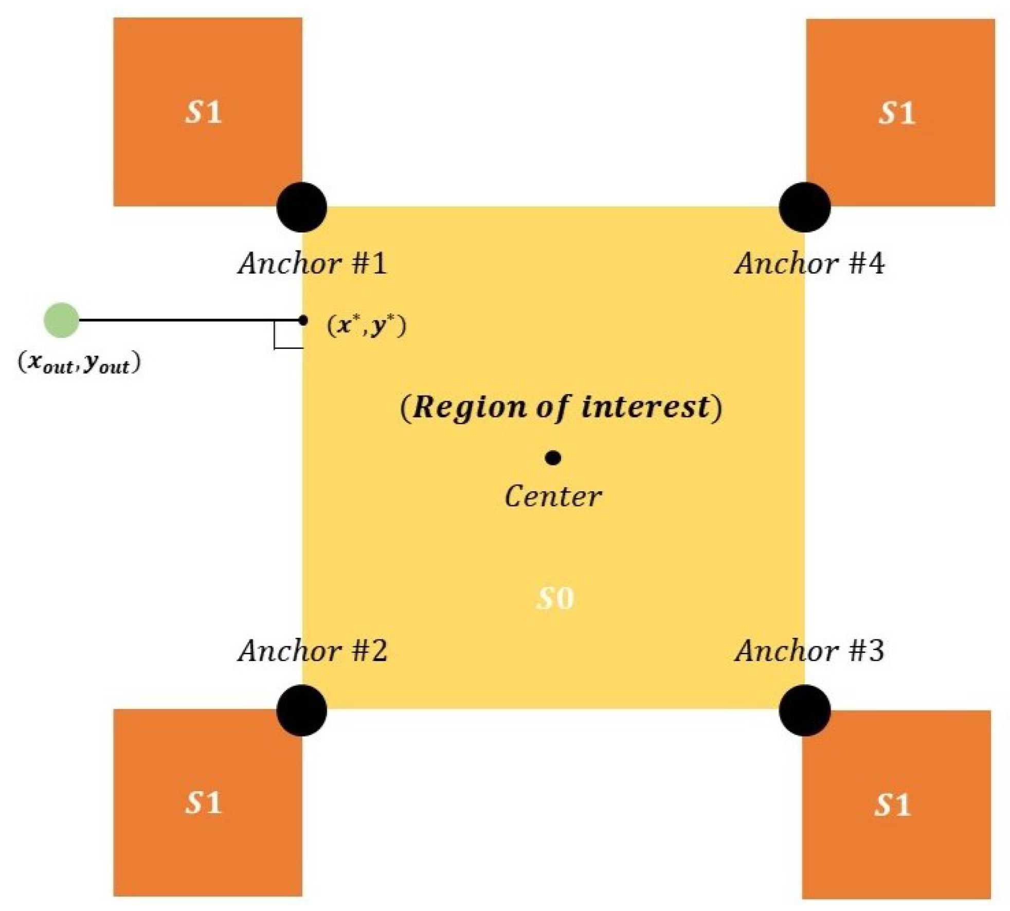
Figure 4.
Conceptual description of Scheme #2.

Figure 5.
Conceptual description of Scheme #3.
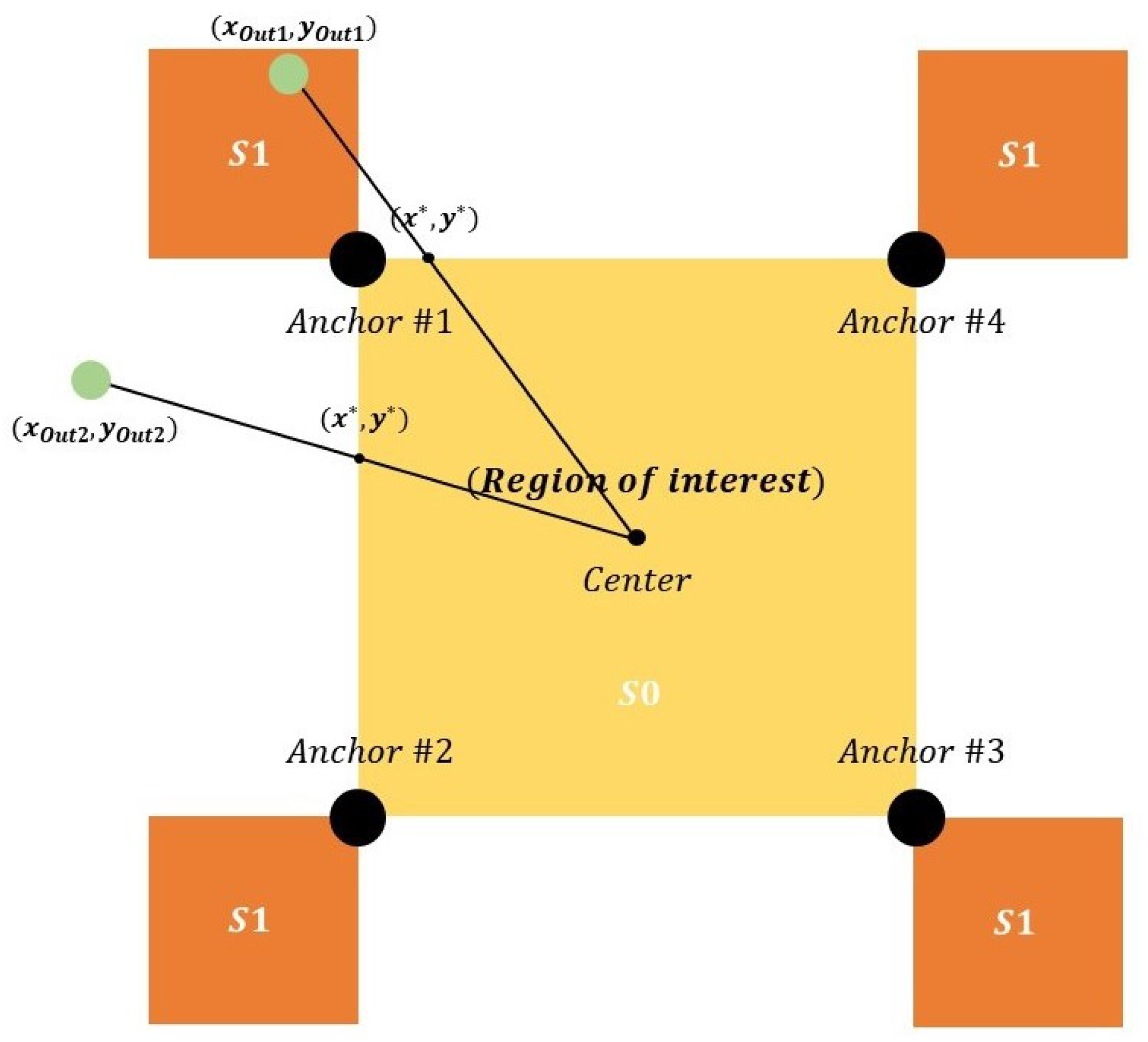
Figure 6.
APE when utilizing four anchors (k = 1).
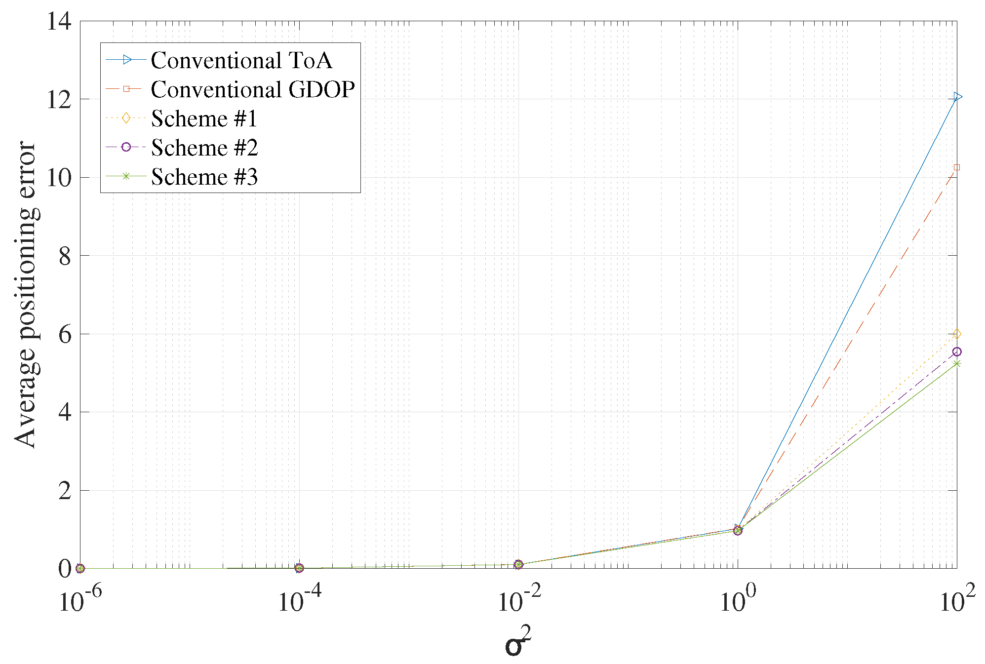
Figure 7.
APE when utilizing eight anchors (k = 2).
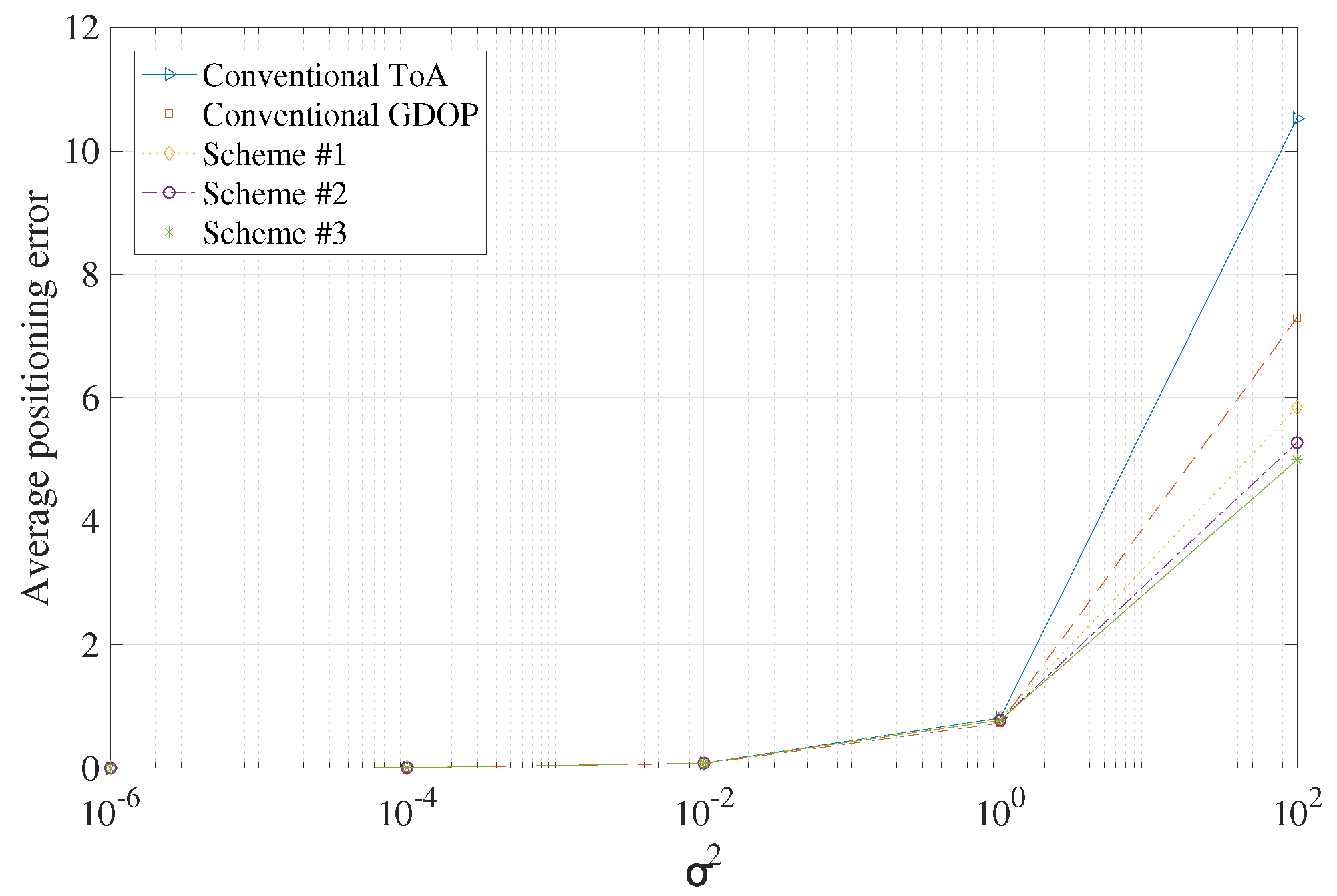
Figure 8.
CDF when utilizing four anchors .

Figure 9.
CDF when utilizing eight anchors .

Table 1.
Three cases according to the applicable method.
| S0 | S1 | S2 | |
|---|---|---|---|
| Conventional ToA | ToA | ||
| Scheme #1 | ToA | Correction of location information based on Euclidean distance | Project to the adjacent boundary by leveraging |
| Scheme #2 | ToA | Correction of location information based on Euclidean distance | Correction of location information by leveraging intersection of the adjacent boundary with the line outside the center |
| Scheme #3 | ToA | Correction of location information by learning intersection of the boundary with the line outside the center | Correction of location information by leveraging intersection of the adjacent boundary with the line outside the center |
Table 2.
Difference when using four anchors.
| Difference in | |||||
|---|---|---|---|---|---|
| Conventional ToA | 0.0000 | 0.0001 | 0.0010 | 0.0072 | 1.8063 |
| Scheme #1 | 0.0000 | 0.0001 | 0.0013 | 0.0509 | 4.2573 |
| Scheme #2 | 0.0000 | 0.0001 | 0.0014 | 0.0616 | 4.7129 |
| Scheme #3 | 0.0000 | 0.0001 | 0.0015 | 0.0614 | 5.0164 |
Table 3.
Difference when using eight anchors.
| Difference in | |||||
|---|---|---|---|---|---|
| Conventional ToA | 0.0000 | 0.0008 | 0.0082 | 0.0840 | 3.2280 |
| Scheme #1 | 0.0000 | 0.0008 | 0.0080 | 0.0738 | 1.4560 |
| Scheme #2 | 0.0000 | 0.0008 | 0.0078 | 0.0477 | 2.0225 |
| Scheme #3 | 0.0000 | 0.0008 | 0.0078 | 0.0481 | 2.3023 |
Disclaimer/Publisher’s Note: The statements, opinions and data contained in all publications are solely those of the individual author(s) and contributor(s) and not of MDPI and/or the editor(s). MDPI and/or the editor(s) disclaim responsibility for any injury to people or property resulting from any ideas, methods, instructions or products referred to in the content. |
© 2024 by the authors. Licensee MDPI, Basel, Switzerland. This article is an open access article distributed under the terms and conditions of the Creative Commons Attribution (CC BY) license (https://creativecommons.org/licenses/by/4.0/).
Share and Cite
MDPI and ACS Style
Park, S.; Hwang, J.; Byun, I.; Choi, S.W. High Accuracy Localization Scheme Using 1-Bit Side Information: Achievability from a GDoP Perspective. Electronics 2024, 13, 1574. https://doi.org/10.3390/electronics13081574
AMA Style
Park S, Hwang J, Byun I, Choi SW. High Accuracy Localization Scheme Using 1-Bit Side Information: Achievability from a GDoP Perspective. Electronics. 2024; 13(8):1574. https://doi.org/10.3390/electronics13081574
Chicago/Turabian StylePark, Suah, Jiyoung Hwang, Ilmu Byun, and Sang Won Choi. 2024. "High Accuracy Localization Scheme Using 1-Bit Side Information: Achievability from a GDoP Perspective" Electronics 13, no. 8: 1574. https://doi.org/10.3390/electronics13081574
Note that from the first issue of 2016, this journal uses article numbers instead of page numbers. See further details here.