
ClosedLoop Control of Pulse-Density-Modulated Wireless Power Transfer with Fast MEPT


1
Electric Power Research Institute, Yunnan Power Grid Co., Ltd., Kunming 650217, China
2
School of Electrical Engineering, Xi’an Jiaotong University, Xi’an 710049, China
*
Author to whom correspondence should be addressed.
Electronics 2024, 13(9), 1619; https://doi.org/10.3390/electronics13091619
Submission received: 2 April 2024
/
Revised: 19 April 2024
/
Accepted: 19 April 2024
/
Published: 24 April 2024
(This article belongs to the Special Issue Wireless Power Transfer Technology and Its Applications)
Abstract
:Efficient wireless power transfer (WPT) requires closedloop control to perform maximum efficiency point tracking (MEPT) against the dynamic changes of operating conditions. In this paper, we took the latest deltasigma pulse-density-modulated (PDM) WPT system as the plant and presented a systematic control design procedure. The WPT system was modeled by the reducedorder dynamic phasor method and further decoupled under the tuned condition. It was identified that the coupled resonators behave like a secondorder system, and its natural frequency is much lower than the resonant frequency. This was considered in the closedloop design to derive a suitable loop gain and ensure stability. The nonlinearity caused by the dualside PDM control is limited to a small inner loop so that the entire loop is linear and simple. Experimental results showed that the closedloop voltage regulation and MEPT took only about 10 ms after load stepping. The system DC output voltage was always tightly regulated, and the steadystate efficiency was very close to the theoretical maximum value under different coupling conditions.
1. Introduction
In the past decade, the field of wireless power transfer (WPT) has emerged as a significant area of research [1]. However, the low energy efficiency is still the bottleneck of its widespread application [2]. Although a WPT system can be well-designed to be efficient at a specific operating point, its efficiency may be greatly reduced when the coupling and load conditions deviate. To solve this problem, researchers have proposed various control methods [3,4,5,6,7,8,9,10,11,12,13] to dynamically maximize the energy efficiency against parameter deviations. In this paper, we collectively refer to these methods as the maximum efficiency point tracking (MEPT).
The basic idea of MEPT is to keep the amplitudes of the coupler resonant currents in the best proportional relationship, so that the required power can be transferred with the minimal total resistive (and hysteresis) loss. This idea can be realized by dualside power conversion. An intuitive way is to add pre and postDC–DC converters to, respectively, control the DC voltages of the transmitterside inverter and receiverside rectifier [6,8,9], or, more directly, use the inverter and active rectifier to control the AC excitation voltages of the coupled resonators by means of either phase shift control [4,11] or pulse density modulation (PDM) [14,15]. Among these methods, PDM has attracted more attention especially in highfrequency WPT systems due to its soft switching capability from zero to full load. These strategies represent promising avenues for enhancing the efficiency of WPT systems and overcoming the current limitations of this technology. For example, an irregular 32 pulse density modulation (PDM)controlled wireless power transfer (WPT) system is proposed for constant current (CC) and constant voltage (CV) outputs [16]. Furthermore, a feedforward power compensation method based on pulse density modulation (PDM) was proposed to improve the impact of phase shift keying (PSK) communication on output power and voltage fluctuations in WPT systems [17]
In addition to hardware implementations, MEPT also requires a closedloop dynamic control system to run correctly. The existing research provides a lot of key supports for this control system. First, the most common dynamical modeling methods for WPT systems include the generalized statespace averaging (GSSA) [17,18], extended describing functions (EDF) [19,20], and dynamic phasors [21,22]. These methods consider not only the dynamic behaviors of the moving averages, but also the timevarying fundamental harmonics of the state variables, such as the resonant currents and AC excitation voltages. The differential equations are derived from the instantaneous time–domain statespace model under two conditions: 1) the higher-order harmonics are negligible, and 2) the frequencies of dynamic perturbations are much lower than the switching frequency. The first condition is also called fundamental harmonic approximation, and the secondary one is due to the halfswitching frequency limit that also applies to the classical moving average model. The modeling methods provide engineers with the tools to rigorously predict system behavior and devise robust control strategies, ensuring systems operate with optimal efficiency and reliability.
However, the dynamical models derived using these methods suffer from high orders and complicated forms due to the complex nature of the coupled resonances and switchedmode power converters in WPT systems. High-order models are difficult to operate in solving practical problems, and the process of calculating and obtaining analytical solutions is full of difficulties. For example, a simple series–series compensated WPT system has four resonant elements and one filter capacitor, which has to be modeled by a ninthorder model [19] using the GSSA or EDF method. To reduce the model order, previous studies proposed model order reduction techniques and presented fifthorder models for the system [21]. Furthermore, the experimental results given in [21] imply that the system may be described by an even simpler model, and drive a further study on the dynamical modeling. Secondly, perturb and observe (P&O) algorithms [5,6,7] and voltage ratio control [3,4,9] are used in MEPT to overcome the parameter uncertainties and changes. P&O algorithms are more robust, while the voltage ratio control is faster and more stable. Third, the wireless data link between the power transmitter and receiver has been built through various communication technologies, e.g., [13,23,24], to achieve dualside co-operation.
However, most of the existing closedloop designs modeled but ignored the dynamic processes of the coupled resonators, e.g., [9], causing the risk of instability. Other studies considered the dynamics of only the power transmitter, e.g., [18], or only the power receiver, e.g., [22], missing the dynamic interactions and nonlinear characteristics of the dualside co-operation. The delay and impact introduced by the wireless data link were rarely considered in the literature. Few studies have proposed a closedloop control for the latest PDM WPT system.
Pulse density modulation (PDM) in wireless power transfer (WPT) systems are a critical technology that enhances the efficiency of energy transfer. By utilizing fixed-frequency soft switching, PDM ensures that the power is transferred smoothly without the hard switching transients that can cause inefficiencies and wear on system components. This method also allows for a rapid response to any changes in the load, which is essential for maintaining a stable power supply and protecting sensitive electronic devices. Moreover, the use of PDM enables a simplified power conversion process by eliminating the need for multiple stages of conversion, thus reducing complexity, cost, and potential points of failure within the system [25]. Furthermore, the communication method employing frequencymodulated phase shift keying (FMPSK) offers a significant advantage in integrating communication capabilities within the WPT system. FMPSK allows for the transmission of control and data signals through the same coil used for power transmission. This integration is highly reliable, as it leverages the existing power transfer infrastructure, which is designed to be robust. Additionally, FMPSK eliminates the necessity for extra hardware devices dedicated to communication, which not only simplifies the overall design but also reduces the weight, space, and cost associated with additional components. The result is a more streamlined and efficient WPT system that can handle both power and data transmission with a high reliability and minimal additional hardware requirements [26]. These advantages are the reasons for selecting the deltasigma PDM WPT system and the FMPSK method for wireless data link establishment over alternative technologies.
For this study, we take the deltasigma (ΔΣ) PDM WPT system [27,28] as the plant for its compact structure and rapid response. The wireless data link is established by the frequencymodulated phase shift keying (FMPSK) method for its high reliability and predictability. The system was modeled with the reducedorder dynamic phasor method [21] for simplicity and further analysis. We identify the natural frequency of the current dynamic phasor subsystem, which is proportional to the coupling coefficient, and limits the loop bandwidth. We also carefully limit the nonlinearity caused by the dualside co-operation to a small inner loop to make the entire closed loop linear and simple. All these efforts provide a systematic and complete design methodology of the closedloop control for PDM WPT system with fast MEPT.
2. Plant Modeling and Simplification
Figure 1 shows the schematic of a ΔΣPDM WPT system with a wireless data link based on FMPSK between the power transmitter and the power receiver for dualside co-operation. The system fixes the switching frequency while it adjusts the pulse densities of the inverter and the rectifier, i.e., d1 and d2, to simultaneously regulate the output voltage and maximize the energy efficiency.
Pulse density modulation (PDM) is a digital signal-processing technique that encodes an analog signal into a binary format by modulating the density of pulses to mirror the signal’s amplitude. In wireless power transfer (WPT) systems, PDM provides advantages for maintaining tuned conditions while ensuring soft switching and robust control capabilities. In the fullbridge converter, which operates without a DC blocking capacitor, a pulse density modulation (PDM) strategy is employed. This strategy leverages the negative feedback produced by the deadtime voltage. The corresponding block diagram is depicted in Figure 2. The input signals consist of a continuous pulse a and a predetermined pulse density b, where the frequency of a is the fundamental switching frequency fs = 1/Ts and b ranges from 0 to 1. The output signals generated are uA* and uB*, (where “*” means the logic reference of the switch node voltage). The PDM strategy utilizes an adder, a comparator, five logic gates, and three delay units, which are activated by the rising and falling edges of the pulse a. Consequently, the strategy operates at an iteration frequency of 2fs. Each iteration involves accumulating the difference between b and the XOR of uA* and uB*, with the result being stored in c. If c is positive, uA* is assigned the value of a; if not, it retains its previous value. Meanwhile, uB* consistently takes on the value of the previous uA*. The strategic deployment of PDM in WPT systems facilitates the generation of symmetric zerovoltageswitching (ZVS) currents, which are essential for achieving optimal ZVS and reducing switching losses. PDM emerges as a promising control strategy for WPT applications, heralding significant advancements in reducing switching losses and bolstering system performance.
The overall operation of the strategy can be described by a set of difference equations:
where n is the index of the iterations, and “”, “”, “”, and “” are the logic symbols of AND, OR, NOT, and XOR, respectively.
2.1. ReducedOrder Dynamic Phasor Model
From the perspective of dynamic control, we focus on the average model of the system, which can be derived from the reducedorder dynamic phasor method [21] and expressed as
where IL1 and IL2 are the complexvalued dynamic phasors of the instantaneous resonant currents, V1 and V2 are the average DC input and output voltages, respectively, and S1 and S2 are the complexvalued switching functions of the converters:
I2 is the rectifier output average current:
Δω1 and Δω2 are the beat frequencies:
ωs is the angular switching frequency, and ωr1 and ωr2 are the resonant frequencies:
Lω1 and Lω2 are the equivalent inductances:
L1 and L2 are the resonator inductances, C1 and C2 are the resonator capacitances, R1 and R2 are the equivalent series resistances (ESRs), M is the mutual inductance between L1 and L2, Cf is the output filter capacitance, and RL is the load resistance.
2.2. Model Decoupling under Tuned Conditions
The system is well-tuned when the resonant frequencies equal the switching frequency, i.e.,
and the switching pulses of the converters are synchronized with the resonant currents so that
With (8) and (9), model (2) is simplified as
which can be decoupled into an uncontrollable part:
and a controllable part:
where IL1r, IL2r and IL1i, IL2i are the real and imaginary parts of IL1 and IL2, respectively.
It can be verified that the uncontrollable part is globally and asymptotically stable. Its unique equilibrium point is
Therefore, we can ignore the uncontrollable part and consider only the controllable part, i.e., (12), which is a thirdorder realvalued nonlinear model.
2.3. Low-Frequency Approximation
To further simplify the model, we regard the first two equations in (12) as a secondorder linear current subsystem whose inputs are (V1d1) and (V2d2):
If the ESRs are much smaller than the mutual reactance, i.e.,
we can approximately express the damping ratio ξ and the natural frequency ωn of the current subsystem (14) as
and
respectively, where Q1 and Q2 are the resonator quality factors:
k is the coupling coefficient:
The damping ratio ξ is usually less than 1 because Q1 and Q2 may reach hundreds or even thousands in an efficient WPT system, and k is greater than 0.01 in most typical applications. Therefore, (14) has a resonant peak at the natural frequency ωn. It should be noted that this resonance refers to the amplitude of the currents rather than their instantaneous values. Its physical meaning is the energy exchange between the LC resonators.
In the frequency range much lower than ωn, we can ignore the dynamic process of the current subsystem (14) and only consider its equilibrium point:
With (20), model (12) is approximated to
where
3. Control Law Design
3.1. Voltage Regulation
We treat (21) as a linear firstorder system whose control input is the product of d1 and d2, and design its control law as
where kp and ki are the proportional and integral coefficients, respectively. It can be proven that, for any positive kp and ki, the closedloop system composed of (21) and (23) is globally and asymptotically stable. However, the rationality of (21) depends on (20). To satisfy (20), kp and ki should be carefully designed so that the gain crossover frequency ωc, which is given by (24), of the closed loop is much lower than the nature frequency ωn given by (17).
Assume that the ranges of k and RL of normal operation are
and
respectively. As per (23), the maximum ωc occurs when k = kmin and RL = +∞:
As per (16), the minimum ωn occurs when k = kmin:
To ensure ωc << ωn for various k and RL, let
To achieve the best dynamic performance at full load, let
By combining (29) and (30), we obtain
where the approximations rely on
3.2. Efficiency Maximization
To simultaneously reach the maximum efficiency and maximum power, the WPT system is designed so that
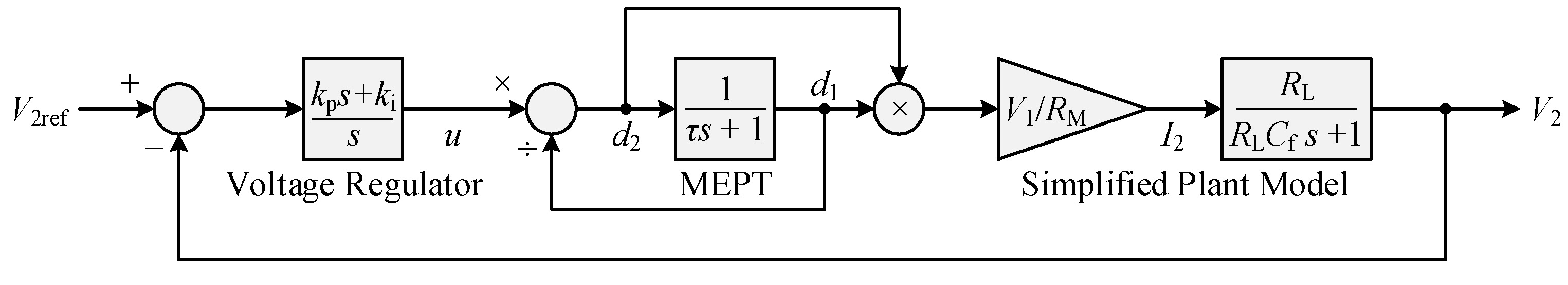
and, therefore, MEPT requires only d1 = d2 [13].
In Figure 1, the controller assigns d1 the same value with d2 through the wireless data link. The dynamic behavior of the data link can be designed and modeled as a firstorder inertia system like
where τ is the time constant that depends on the data link.
By combining (23) and (34), we obtain
which is nonlinear but globally and asymptotically stable. We use (35) to estimate d1 and calculate d2 (see Figure 3) since d1 is not directly measured by the controller.
4. Experimental Verification
Figure 4 and Table 1 shows the experimental prototype and its associated parameters, respectively. The experimental prototype consists of key components such as a GaN Inverter, a Zynq Controller, and a Transmitter Coil on the power input side, and a Receiver Coil, another Zynq Controller, and a GaN Rectifier on the power output side. The system operates by transmitting power wirelessly from the transmitter coil to the receiver coil over a distance of 20–30 cm. We tuned the prototype by setting its switching frequency fs to the resonant frequencies fr1,2 and synchronizing the rectifier gate drive signals with the receiver resonant current. By aligning the switching frequency with these resonant frequencies, the system can operate at its peak efficiency, thereby minimizing energy losses and maximizing power transfer. In addition, the synchronization of the rectifier gate drive signal with the receiver resonant current ensures smooth and seamless energy transmission from the transmitter to the receiver, helping to maintain a stable and reliable output, making the system operate more efficiently and effectively.
The power loss in a WPT system is primarily attributed to the conduction loss in coils, radiation loss, conduction loss in power semiconductors, and switching loss. These losses are contingent upon the system’s operational parameters, such as the operating frequency and resonant current. To represent the cumulative power losses, we employ the concept of equivalent series resistance (ESR) R1 and R2. At a constant load resistance, a specific coupling coefficient corresponds to the peak voltage gain. It is widely recognized that the point of maximum efficiency coincides with the operating frequency matching the resonant frequency at the receiver. To mitigate power reflection and minimize ESR losses which are influenced by mutual inductance, the equivalent load resistance must be optimized. Matching the load resistance with the ESRs also harmonizes the currents at the transmission and reception points, thereby optimizing system efficiency.
The matching between load resistance and ESR is
where the figureofmerit is related to the mutual inductance:
When the operating frequency equals the receivingside resonant frequency and (36) are satisfied, the maximum efficiency is
In the experimental setup, the EPC9006C development board served as the core component for both the inverter and rectifier. Manufactured by the Efficient Power Conversion Corporation (EPC), this board is a robust halfbridge solution capable of handling up to 100 V and delivering a maximum current of 7 A. It integrates two EPC2007C eGaN FETs in a halfbridge arrangement and features the Texas Instruments LM5113 gate driver, complete with necessary supply and bypass capacitors. The EPC9006C is meticulously engineered for a superior switching performance, offering multiple probe points to facilitate a straightforward waveform analysis and efficiency optimization.
The coupling coil formers within the WPT system was fabricated utilizing 3D printing technology. The coil’s principal design specifications include an outer diameter of 30 cm, a turn count of 10, and a wire diameter of 1 mm with an equivalent spacing of 1 mm between wires. The coil has an inductance of 63 µH, the power transmission range of the system spans from 20 cm to 30 cm, and the coil’s coupling coefficient varied between 0.063 and 0.03. In the process of selecting component parameters, we chose the type of Litz wire based on the switching frequency, and selected the filtering capacitor based on the ripple requirements of the DC voltage. In our configuration, we employed 46AWG Litz wire, characterized by a single strand diameter of 35 µm and comprising approximately 1000 strands. Moreover, the resonant capacitor are multilayer ceramic capacitors from AVX. Multiple capacitors of different capacitances were parallelly connected to set the resonant frequency equal to the switching frequency. The switching frequency was fixed by the digital controller.
Therefore, both (8) and (9) were satisfied. Moreover, we used 46 AWG Litz wire to wind the coils to reduce the ESRs R1,2 and satisfy (15) even if the coupling coefficient k took its minimum value. This selection of materials and design parameters ensured that the system would function optimally under a wide range of conditions. With these preconditions, the natural frequency of the current subsystem was derived from (17) as fn = 15~31.5 kHz, and shown in Figure 5. The filter capacitance Cf was large enough to satisfy (32) even if the load resistance RL took its minimum value. This ensured that the system would remain stable and efficient even under heavy load conditions. Therefore, the proportional and integral gains could be derived from (31) as kp = 0.294 and ki = 55.5. With these values, the gain crossover frequency of the closed loop was derived from (24) as fc = 0.71~1.5 kHz and shown in Figure 6. Antiwindup and overvoltage/current protection functions were also added to the control code. These safety features were crucial for preventing damage to the system and ensuring reliable operation under various operating conditions. In addition, according to the parameters listed in Table 1, the theoretical maximum efficiency of the prototype was ηmax = 84.6~92.3%, which corresponds to k = 0.03~0.63, and power transfer distance was 30 cm to 20 cm.
We evaluated the dynamic performance of the prototype by alternating the load resistance RL between 50 Ω and 100 Ω. The 50 Ω load resistance represented a fullload scenario, while the 100 Ω load resistance corresponded to a halfload situation. And we captured waveforms under two conditions: when the coupling coefficient k was at its minimum value (kmin = 0.03), represented in Figure 7, and when k was at its maximum value (kmax = 0.063), depicted in Figure 8. Across all these scenarios, the output voltage v2 was consistently regulated to match its reference value of 50 V. This tight regulation ensures that the system can reliably deliver the desired output voltage under varying load conditions. Across all these scenarios, the output voltage v2 was consistently regulated to match its reference value of 50 V. This tight regulation ensures that the system can reliably deliver the desired output voltage under varying load conditions. Moreover, the amplitudes of the resonant currents iL1 and iL2 always maintained a fixed proportional relationship, regardless of the load resistance or the value of k. This consistent relationship is crucial for maximizing the efficiency of the system, as confirmed by the data listed in Table 2. Moreover, the dynamic processes of voltage regulation and maximum efficiency point tracking (MEPT) were completed in approximately 10 ms. In applications with a timevarying coupling coefficient or load, fast voltage stabilization ensures the safety and reliability of the system, and fast maximum efficiency tracking ensures a high average efficiency.
The regulator used in this article implements a proportional–integral control strategy for output voltage. The main control strategy is shown in (23), which controls the system with the proportional and integral coefficients kp and ki. Figure 6 shows the controller model of the system and the Bode plot of the loop gain. The different curves represent the system behaviors under different conditions where the coupling coefficient varies between 0.03 and 0.063, and the load varies from 50 ohms to infinity.
Table 3 presents a comparative analysis of the voltage regulation duration in wireless charging systems equipped with closedloop voltage control and maximum efficiency tracking features documented in the current literature and the system presented in this paper. Furthermore, the communication approach employed herein offers significant benefits, including the elimination of the need for supplementary communication modules, thereby ensuring low costs and enhanced system reliability.
5. Conclusions
This article proposes the closedloop control of the PDM WPT system based on the reducedorder dynamic phasor model. It is shown that the tuned coupled resonators behave like a secondorder system, and their nature frequency is much lower than the LC resonant frequency. The nature frequency limits the closedloop bandwidth and determines the controller gain. The dualside PDM control is nonlinear in nature, but it can be handled properly to make the entire loop linear and simple. Through a welldesigned closedloop, the voltage regulation and MEPT processes of the PDM WPT system can be as short as 10 ms, which makes the dynamic WPT more stable and efficient. The closedloop control method proposed in this paper offers a solution for the wireless power transfer systems with dualside co-operative control, ensuring rapid and stable voltage output while maintaining maximum efficiency. This method is particularly suitable for systems experiencing variations in the coupling coefficient or load power, such as the wireless charging of hovering drones, underwater vehicles, and electric vehicles in motion.
Author Contributions
Conceptualization, K.W. and H.L.; methodology, H.L. and H.J.; hardware design and software, K.W. and J.P.; validation, K.W., J.P. and H.L.; formal analysis, K.W.; investigation, H.J.; resources, K.W. and J.P.; data curation, H.L.; writing—original draft preparation, H.L.; writing—review and editing, H.J.; visualization, K.W.; project administration, J.P. All authors have read and agreed to the published version of the manuscript.
Funding
This work was supported by the China Southern Power Grid under Grant YNKJXM20222524.
Data Availability Statement
Some or all of the data during this study are available from the corresponding author upon request.
Conflicts of Interest
Ke Wang and Jing Peng are employed by the company Yunnan Power Grid Co., Ltd. The other authors declare no conflicts of interest.
References
- Song, M.; Jayathurathnage, P.; Zanganeh, E.; Krasikova, M.; Smirnov, P.; Belov, P.; Kapitanova, P.; Simovski, C.; Tretyakov, S.; Krasnok, A. Wireless power transfer based on novel physical concepts. Nat. Electron. 2021, 4, 707–716. [Google Scholar] [CrossRef]
- Zhang, Z.; Pang, H.; Georgiadis, A.; Cecati, C. Wireless power transfer—An overview. IEEE Trans. Ind. Electron. 2019, 66, 1044–1058. [Google Scholar] [CrossRef]
- Ishihara, H.; Moritsuka, F.; Kudo, H.; Obayashi, S.; Itakura, T.; Matsushita, A.; Mochikawa, H.; Otaka, S. A voltage ratio-based efficiency control method for 3 kW wireless power transmission. In Proceedings of the 2014 IEEE Applied Power Electronics Conference and Exposition—APEC 2014, Fort Worth, TX, USA, 16–20 March 2014; pp. 1312–1316. [Google Scholar]
- Diekhans, T.; De Doncker, R.W. A dual-side controlled inductive power transfer system optimized for large coupling factor variations and partial load. IEEE Trans. Power Electron. 2015, 30, 6320–6328. [Google Scholar] [CrossRef]
- Fu, M.; Yin, H.; Zhu, X.; Ma, C. Analysis and tracking of optimal load in wireless power transfer systems. IEEE Trans. Power Electron. 2015, 30, 3952–3963. [Google Scholar] [CrossRef]
- Li, H.; Li, J.; Wang, K.; Chen, W.; Yang, X. A maximum efficiency point tracking control scheme for wireless power transfer systems using magnetic resonant coupling. IEEE Trans. Power Electron. 2015, 30, 3998–4008. [Google Scholar] [CrossRef]
- Zhong, W.X.; Hui, S.Y.R. Maximum Energy Efficiency Tracking for Wireless Power Transfer Systems. IEEE Trans. Power Electron. 2015, 30, 4025–4034. [Google Scholar] [CrossRef]
- Dai, X.; Li, X.; Li, Y.; Hu, A.P. Maximum efficiency tracking for wireless power transfer systems with dynamic coupling coefficient estimation. IEEE Trans. Power Electron. 2018, 33, 5005–5015. [Google Scholar] [CrossRef]
- Huang, Z.; Wong, S.-C.; Tse, C.K. Control design for optimizing efficiency in inductive power transfer systems. IEEE Trans. Power Electron. 2018, 33, 4523–4534. [Google Scholar] [CrossRef]
- Zhong, W.; Hui, S.Y.R. Maximum energy efficiency operation of series-series resonant wireless power transfer systems using on-off keying modulation. IEEE Trans. Power Electron. 2018, 33, 3595–3603. [Google Scholar] [CrossRef]
- Li, Y.; Hu, J.; Chen, F.; Li, Z.; He, Z.; Mai, R. Dual-Phase-Shift Control Scheme with Current-Stress and Efficiency Optimization for Wireless Power Transfer Systems. IEEE Trans. Circuits Syst. I Regul. Pap. 2018, 65, 3110–3121. [Google Scholar] [CrossRef]
- Pahlavan, S.; Ashtiani, S.J. Rotation-Tolerant Wireless Power Transmission Scheme with Smart Positioning for Cognitive Research on Moving Animals. IEEE Trans. Biomed. Circuits Syst. 2024, 18, 123–130. [Google Scholar] [CrossRef] [PubMed]
- Pahlavan, S.; Shooshtari, M.; Jafarabadi Ashtiani, S. Star-Shaped Coils in the Transmitter Array for Receiver Rotation Tolerance in Free-Moving Wireless Power Transfer Applications. Energies 2022, 15, 8643. [Google Scholar] [CrossRef]
- Yenil, V.; Cetin, S. An Improved Pulse Density Modulation Control for Secondary Side Controlled Wireless Power Transfer System Using LCC-S Compensation. IEEE Trans. Ind. Electron. 2022, 69, 12762–12772. [Google Scholar] [CrossRef]
- Wang, C.; Fan, Y.; Gao, W.; Wang, K.; Li, H. PDM-Based Feedforward Power Compensation for FMPSK Communication in WPT Systems. IEEE Trans. Circuits Syst. II Express Briefs 2022, 69, 2241–2245. [Google Scholar] [CrossRef]
- Unal, K.; Bal, G.; Oncu, S. Implementation of the irregular pulse density modulation-controlled wireless power transfer system for constant current and constant voltage output. Int. J. Circuit Theory Appl. 2023, 1–18. [Google Scholar] [CrossRef]
- Hu, A.P. Modeling a contactless power supply using GSSA method. In Proceedings of the 2009 IEEE International Conference on Industrial Technology, Churchill, VIC, Australia, 10–13 February 2009; pp. 1–6. [Google Scholar]
- Hao, H.; Covic, G.A.; Boys, J.T. An approximate dynamic model of LCL-T-based inductive power transfer power supplies. IEEE Trans. Power Electron. 2014, 29, 5554–5567. [Google Scholar] [CrossRef]
- Zahid, Z.U.; Dalala, Z.M.; Zheng, C.; Chen, R.; Faraci, W.E.; Lai, J.-S.J.; Lisi, G.; Anderson, D. Modeling and control of series-series compensated inductive power transfer system. IEEE J. Emerg. Sel. Top. Power Electron. 2015, 3, 111–123. [Google Scholar] [CrossRef]
- Lyu, S.; Chen, W.; Hu, X. Stability Analysis of Wireless Power Transfer System Based on Extended Describing Function. In Proceedings of the 2022 IEEE Transportation Electrification Conference and Expo, Asia-Pacific (ITEC Asia-Pacific), Haining, China, 28–31 October 2022; pp. 1–5. [Google Scholar] [CrossRef]
- Li, H.; Fang, J.; Tang, Y. Dynamic phasor-based reduced-order models of wireless power transfer systems. IEEE Trans. Power Electron. 2019, 34, 11361–11370. [Google Scholar] [CrossRef]
- Lee, S.; Choi, B.; Rim, C.T. Dynamics characterization of the inductive power transfer system for online electric vehicles by Laplace phasor transform. IEEE Trans. Power Electron. 2013, 28, 5902–5909. [Google Scholar] [CrossRef]
- Wu, J.; Zhao, C.; Lin, Z.; Du, J.; Hu, Y.; He, X. Wireless power and data transfer via a common inductive link using frequency division multiplexing. IEEE Trans. Ind. Electron. 2015, 62, 7810–7820. [Google Scholar] [CrossRef]
- Ahn, D.; Kim, S.; Moon, J.; Cho, I.K. Wireless power transfer with automatic feedback control of load resistance transformation. IEEE Trans. Ind. Electron. 2016, 31, 7876–7886. [Google Scholar] [CrossRef]
- Ye, W.; Chen, X.; Liu, F. Pulse Density Modulation Control to Achieve Constant Output Voltage for Multi-load Magnetically Coupled Resonant Wireless Power Transfer System. In Proceedings of the 10th International Conference on Power Electronics, Machines and Drives (PEMD 2020), Online, 15–17 December 2020; pp. 222–229. [Google Scholar] [CrossRef]
- Ishii, M.; Nakanishi, K.; Sasaki, M. High Efficiency Frequency Shift Keying Data Transmission System using Magnetic Resonance Wireless Power Transfer. In Proceedings of the 2018 IEEE Wireless Power Transfer Conference (WPTC), Montreal, QC, Canada, 3–7 June 2018; pp. 1–4. [Google Scholar] [CrossRef]
- Li, H.; Chen, S.; Fang, J.; Tang, Y.; de Rooij, M.A. A low-subharmonic, full-range, and rapid pulse density modulation strategy for ZVS full-bridge converters. IEEE Trans. Power Electron. 2019, 34, 8871–8881. [Google Scholar] [CrossRef]
- Mishima, T.; Lai, C.-M. Load-Adaptive Resonant Frequency-Tuned Δ–Σ Pulse Density Modulation for Class-D ZVS High-Frequency Inverter-Based Inductive Wireless Power Transfer. IEEE J. Emerg. Sel. Top. Ind. Electron. 2022, 3, 411–420. [Google Scholar] [CrossRef]
- Mai, R.; Liu, Y.; Li, Y.; Yue, P.; Cao, G.; He, Z. An active-rectifier-based maximum efficiency tracking method using an additional measurement coil for wireless power transfer. IEEE Trans. Power Electron. 2018, 33, 716–728. [Google Scholar] [CrossRef]
Figure 1.
Schematic of a ΔΣPDM WPT system with a wireless data link.

Figure 2.
Block diagram of the PDM strategy [27].
Figure 2.
Block diagram of the PDM strategy [27].

Figure 3.
Control diagram of the WPT system.

Figure 4.
Experimental prototype.

Figure 5.
Bode diagrams of the current subsystem when the coupling coefficient k varies from 0.03 to 0.063.
Figure 5.
Bode diagrams of the current subsystem when the coupling coefficient k varies from 0.03 to 0.063.

Figure 6.
Bode diagrams of the voltage regulator, simplified plant model, and loop gain when the coupling coefficient k varies from 0.03 to 0.063 and the load resistance RL varies from 50 Ω to +∞.
Figure 6.
Bode diagrams of the voltage regulator, simplified plant model, and loop gain when the coupling coefficient k varies from 0.03 to 0.063 and the load resistance RL varies from 50 Ω to +∞.

Figure 7.
Experimental waveforms when k = 0.03: (a) RL stepped between 50 Ω and 100 Ω; (b) RL = 50 Ω; (c) RL = 100 Ω.
Figure 7.
Experimental waveforms when k = 0.03: (a) RL stepped between 50 Ω and 100 Ω; (b) RL = 50 Ω; (c) RL = 100 Ω.


Figure 8.
Experimental waveforms when k = 0.063: (a) RL stepped between 50 Ω and 100 Ω; (b) RL = 50 Ω; (c) RL = 100 Ω.
Figure 8.
Experimental waveforms when k = 0.063: (a) RL stepped between 50 Ω and 100 Ω; (b) RL = 50 Ω; (c) RL = 100 Ω.


Table 1.
Prototype parameters.
| Symbol | Quantity | Value |
|---|---|---|
| L1,2 | Resonant inductances | 63.3 μH |
| C1,2 | Resonant capacitances | 400 pF |
| R1,2 | Equivalent series resistances | 1 Ω |
| Q1,2 | Resonant quality factors | 400 |
| fr1,2 | Resonant frequencies | 1 MHz |
| fs | Switching frequency | 1 MHz |
| Cf | Output filter capacitance | 106 μF |
| v1 | Input DC voltage | 50 V |
| v2ref | Output DC voltage reference | 50 V |
| k | Coupling coefficient | 0.03~0.063 |
| RL | Load resistance | 50~+∞ Ω |
| kp | Proportional gain of the voltage regulator | 0.294 |
| ki | Integral gain of the voltage regulator | 55.5 |
| τ | Time constant of the wireless data link | 5 ms |
Table 2.
Prototype efficiency.
| Operating Condition | Theoretical Maximum Value | Measured Value |
|---|---|---|
| Power transfer distance = 30 cm, k = 0.03, RL = 100 Ω | 84.6% | 83.9% |
| Power transfer distance = 30 cm, k = 0.03, RL = 50 Ω | 84.6% | 84.3% |
| Power transfer distance = 20 cm, k = 0.063, RL = 100 Ω | 92.3% | 90.6% |
| Power transfer distance = 20 cm, k = 0.063, RL = 50 Ω | 92.3% | 91.9% |
Disclaimer/Publisher’s Note: The statements, opinions and data contained in all publications are solely those of the individual author(s) and contributor(s) and not of MDPI and/or the editor(s). MDPI and/or the editor(s) disclaim responsibility for any injury to people or property resulting from any ideas, methods, instructions or products referred to in the content. |
© 2024 by the authors. Licensee MDPI, Basel, Switzerland. This article is an open access article distributed under the terms and conditions of the Creative Commons Attribution (CC BY) license (https://creativecommons.org/licenses/by/4.0/).
Share and Cite
MDPI and ACS Style
Wang, K.; Jiang, H.; Peng, J.; Li, H. ClosedLoop Control of Pulse-Density-Modulated Wireless Power Transfer with Fast MEPT. Electronics 2024, 13, 1619. https://doi.org/10.3390/electronics13091619
AMA Style
Wang K, Jiang H, Peng J, Li H. ClosedLoop Control of Pulse-Density-Modulated Wireless Power Transfer with Fast MEPT. Electronics. 2024; 13(9):1619. https://doi.org/10.3390/electronics13091619
Chicago/Turabian StyleWang, Ke, Haiyue Jiang, Jing Peng, and Hongchang Li. 2024. "ClosedLoop Control of Pulse-Density-Modulated Wireless Power Transfer with Fast MEPT" Electronics 13, no. 9: 1619. https://doi.org/10.3390/electronics13091619
Note that from the first issue of 2016, this journal uses article numbers instead of page numbers. See further details here.