
Cooperative Lane-Change Control Method for Freeways Considering Dynamic Intelligent Connected Dedicated Lanes


1
National Engineering Research Center of Highway Maintenance Technology, Changsha University of Science & Technology, Changsha 410114, China
2
School of Traffic & Transportation Engineering, Changsha University of Science & Technology, Changsha 410114, China
3
Ulanqab Vocational College, Ulanqab 012000, China
*
Author to whom correspondence should be addressed.
Electronics 2024, 13(9), 1625; https://doi.org/10.3390/electronics13091625
Submission received: 29 March 2024
/
Revised: 18 April 2024
/
Accepted: 22 April 2024
/
Published: 24 April 2024
(This article belongs to the Special Issue Control Systems for Autonomous Vehicles)
Abstract
:Connected Autonomous Vehicle (CAV) dedicated lanes can spatially eliminate the disturbance from Human-Driven Vehicles (HDVs) and increase the probability of vehicle cooperative platooning, thereby enhancing road capacity. However, when the penetration rate of CAVs is low, CAV dedicated lanes may lead to a waste of road resources. This paper proposes a cooperative lane-changing control method for multiple vehicles considering Dynamic Intelligent Connected (DIC) dedicated lanes. Initially, inspired by the study of dedicated bus lanes, the paper elucidates the traffic regulations for DIC dedicated lanes, and two decision-making approaches are presented based on the type of lane-change vehicle and the target lane: CAV autonomous cooperative lane change and HDV mandatory cooperative lane change. Subsequently, considering constraints such as acceleration, speed, and safe headway, cooperative lane-change control models are proposed with the goal of minimizing the weighted sum of vehicle acceleration and lane-change duration. The proposed model is solved by the TOPSIS multi-objective optimization algorithm. Finally, the effectiveness and advancement of the proposed cooperative lane-changing method are validated through simulation using the SUMO software (Version 1.19.0). Simulation results demonstrate that compared to traditional lane-changing models, the autonomous cooperative lane-changing model for CAVs significantly improves the success rate of lane changing, reduces lane-changing time, and causes less speed disturbance to surrounding vehicles. The mandatory cooperative lane-changing model for HDVs results in shorter travel times and higher lane-changing success rates, especially under high traffic demand. The methods presented in this paper can notably enhance the lane-changing success rate and traffic efficiency while ensuring lane-changing safety.
1. Introduction
Lane changing is a common and fundamental driving behavior that occurs during vehicle movement, involving interactions with multiple surrounding vehicles. This can lead to traffic disruptions and increase the likelihood of traffic accidents [1]. In a connected environment, lane management is an effective means to enhance the efficiency of mixed traffic flow. The fully real-time communication capabilities of CAVs and the development of RSU technology provide conditions for solving efficient lane-change control. However, under different lane management strategies, the scenarios of vehicle lane changes vary, and the types of vehicles changing lanes also differ, which increases the complexity of lane-change decisions and control. Studying vehicle lane-change decisions under vehicle management strategies is important for improving the efficiency and safety of mixed traffic flow under lane management policies.
Accurate lane-changing decisions can minimize the impact on surrounding vehicles, thereby maximizing traffic safety. Traditional lane-changing models have typically focused on the behavior of individual traffic participants, establishing a set of rules from the perspective of these participants to determine whether to change lanes under different conditions. Decision models include rule-based decision models [2,3,4,5], gap acceptance models [6,7], and models based on acceleration thresholds [8]. In rule-based lane-changing decision models, drivers make decisions based on multiple rules, such as lane selection preferences, the necessity of lane changing, and the feasibility of lane changing [2]. The earliest rule-based intention model for lane changing is the Gipps model, which considers the influence of obstacles and traffic control on driving intentions. This model structures the framework for lane changing into three parts: lane-changing intention, conditions, and execution [3]. The flexibility of this model in terms of adding or replacing various reasons for lane changing laid the foundation for the development of lane-changing theories. However, it does not consider driver behavior, and it is limited in scope. Building on the Gipps model, many studies, such as [4,5], have further developed lane-changing decision models that factor in the randomness of driver behavior, leading to the development of the MITSIM and CORSIM models, respectively. In gap acceptance models, gap acceptance is a key factor that drivers consider in the lane-changing decision process [6]. For example, [7] considered the role of minimum gap theory in autonomous dynamic lane-changing trajectory planning and proposed a trajectory planning model based on the minimum gap. Acceleration threshold models often use vehicle acceleration as a criterion for executing a lane change. If a vehicle’s acceleration reaches a predefined threshold, it is deemed capable of performing a lane change. Reference [8] also studied the change in the longitudinal acceleration of vehicles involved in lane change and proposed the MOBIL model, which minimizes the total braking of vehicles, using acceleration to represent the utility of a given lane and the risks associated with changing lanes. This model provided general safety and incentive criteria for symmetric and asymmetric traffic rules.
While the aforementioned models are applicable to macroscopic traffic flow lane-changing decisions in regular lanes, they lack vehicle cooperation and only focus on individual traffic participants, simplifying the real-world scenarios of multiple participants changing lanes simultaneously. Additionally, when considering only a single lane-changing vehicle, CAVs may struggle to adapt to the randomness of HDVs, making it difficult for these models to adapt to the new traffic environment of mixed driving.
The advancement of artificial intelligence technology has provided new insights into lane-changing control. It can predict and simulate surrounding traffic conditions and the uncertain behaviors of drivers more effectively, thus achieving effective lane-changing control. In the recognition of lane-changing intentions, methods based on machine learning have been extensively explored, including support vector machines (SVMs) [9], Bayesian networks [10], hidden Markov models (HMMs) [11], neural networks [12], and Long Short-Term Memory (LSTM) [13] methods, among others. For instance, reference [9] considered multiple factors influencing vehicle lane-changing decisions, established a vehicle lane-changing decision model based on a particle swarm optimization algorithm and the standard SVM, and validated its efficiency through simulation using the NGSIM dataset. Reference [10] developed a vehicle lane-changing decision model based on Bayesian networks, taking into account relevant characteristic parameters such as the lane-changing vehicle’s own speed and acceleration and the relative time gap between interacting vehicles. The model was then validated through comparative simulations with the NGSIM dataset. Similarly, reference [12], using a CNN-GRU combination and integrating an attention mechanism, proposed a vehicle lane-changing intention recognition model that uses vehicle trajectory data to construct a sample set of three lane-changing intentions: left lane changing, right lane changing, and straight driving. The lane-changing behavior was then accurately identified through the intention recognition model. In terms of lane-changing trajectory prediction, there are methods based on Model Predictive Control (MPC) [14], Bezier curve methods [15], deep learning [16], and data-driven approaches [16]. For example, reference [14] considered multiple objectives, such as traffic stability, driving comfort, and timely lane-changing response, and developed a hybrid integer nonlinear programming optimizer based on MPC to optimize lane-changing decisions.
The lane-changing decision models based on machine learning, MPC, and other methods have a certain control effect through the recognition of lane-changing intentions followed by decision making and trajectory control. However, these methods require a certain amount of historical data for short-term prediction and so do not meet the real-time precise control requirements for mixed traffic flows in connected environments.
In a connected environment, CAVs have access to richer information, more powerful computational capabilities, and more precise control, which allows them to complete lane-changing maneuvers more efficiently and safely compared to HDVs. Consequently, the problem of vehicle lane-changing decision making and control in a connected environment has been widely studied, with typical methods including lane-changing models based on game theory [17,18,19] and on safe gap theory [20,21]. Lane-changing decisions based on game theory differ from traditional lane-changing theories by incorporating the states of surrounding vehicles in both the current lane and the target lane into the decision-making process, reflecting the interactions between the subject vehicle and surrounding vehicles [17]. For example, reference [17] considered the influence of surrounding vehicle states and constructed a dynamic game-based lane-changing decision model for multiple CAVs using game theory. The authors also proposed a polynomial-based CAV lane-changing trajectory planning model that balances safety and efficiency. Likewise, reference [18] built a cooperative lane-changing decision model for multiple CAVs under the influence of HDVs based on coalition games (CG-based), integrating the perceived risk field theory to accommodate the uncertainty of HDV motion states. They designed cooperative and non-cooperative game strategies to address the different lane-changing game participants among CAVs. Meanwhile, reference [19] modeled driver behavior and drivers’ gains within a game-theoretic framework and proposed a lane-changing pricing strategy that encourages cooperation between two vehicles during a lane change through the implementation of lane-changing penalties. As for lane-changing decision models based on safe gap theory, reference [20] used the worst-case braking scenario of the preceding CAV and the severity of potential collisions to define safety risks, based on safe gap theory. They constructed a decentralized cooperative lane-changing model for autonomous safe lane changing of CAVs. And reference [21] proposed a coordinated lane-changing relaxed strategy for a CAV dedicated lane on freeways, considering the case of a single CAV merging into a CAV platoon. The authors built a CAV lane-changing decision model based on a safe gap selection model, where the relaxation model controls the longitudinal speed of following vehicles in the CAV platoon to provide an appropriate safe gap for the merging CAV.
The abovementioned lane-changing models in a connected environment only consider cooperative lane changing among CAVs and are mostly for autonomous decision making; they do not involve forced lane changing, nor do they address coordination between CAVs and HDVs during CAV lane changes or between CAVs and HDVs during HDV lane changes. Additionally, the application scenarios primarily involve lane-changing decisions for regular lanes, with limited research focusing on dedicated lane contexts, neglecting the unique characteristics of dedicated lanes.
Consequently, addressing some of the research gaps in the current state of affairs, this paper takes into consideration the characteristics of dedicated lanes and proposes a DIC dedicated lane strategy. Under this lane strategy and taking into account lane properties, the research delves into the lane-changing decision problems in mixed traffic flows for CAVs and HDVs, grounded in the theory of safe following gaps. It presents distinct frameworks for CAV autonomous cooperative lane change and HDV mandatory cooperative lane change. A vehicle lane-changing decision model is constructed and solved, with the model’s effectiveness subsequently corroborated through simulation conducted using the SUMO platform.
The contributions of this paper are as follows: (1) Taking into account the characteristics of dedicated lanes, the concept of a DIC dedicated lane is proposed, and a lane-changing decision framework for mixed traffic flows is established. (2) Different types of collaborative lane-changing decision models for multiple vehicles under lane management strategies are optimized. Based on the theory of safe gaps, autonomous and mandatory lane-change decision models for collaborative CAVs and HDVs are constructed, respectively. (3) Based on the lane-changing decision models and employing multi-objective optimization algorithms, the study explores the optimal solutions for different types of lane-changing behaviors of CAVs and HDVs under various lane management strategies.
The organization of the remainder of this article is as follows: Section 2 introduces the scenarios and problem and proposes a lane-changing decision framework. Section 3 constructs different types of lane-changing decision models based on the theory of safe gaps. In Section 4, simulation experiments are constructed using the SUMO simulation software (Version 1.19.0) to verify the effectiveness of the proposed models. Finally, Section 5 presents the research conclusions.
2. Methodology
2.1. Scene and Problem Description
Over an extended future period, the penetration rate of CAVs will exhibit a slow growth phase, making a transition period of mixed CAV and HDV traffic unavoidable. Existing research [22] has shown that segregating CAVs and HDVs in separate lanes can increase the possibility of CAV platooning, thereby significantly enhancing road capacity. However, when the penetration rate of CAVs is low, setting up CAV dedicated lanes may not fully realize their potential, leading to a waste of road resources [23], especially on freeways. Therefore, inspired by the concept of dedicated bus lanes in urban areas, this paper introduces a DIC dedicated lane concept for multi-lane freeways [24], as illustrated in Figure 1. For the leading Cooperative Adaptive Cruise Control (CACC) or Adaptive Cruise Control (ACC) vehicles in the DIC dedicated lane, a clear distance is established ahead of them. HDVs located within the clear distance must exit the dedicated lane, while HDVs upstream of the CAVs and downstream of the clear distance may enter and travel in the dedicated lane. Depending on the type of vehicle that makes a lane change and the target lane, collaborative lane-changing scenarios are divided into CAV autonomous cooperative lane changes and HDV mandatory cooperative lane changes.
In order to facilitate discussion based on the research scenario, this paper proposes the following assumptions:
- (1)
- All CAVs are capable of obtaining operational information about surrounding vehicles and receiving control commands from RSUs through vehicle-to-vehicle, vehicle-to-infrastructure, and vehicle-to-cloud communications, and they fully comply with these control instructions. HDVs strictly adhere to a car-following model control.
- (2)
- Communication delays are not considered; all information is exchanged in real-time.
- (1)
- CAV autonomous cooperative lane change
CAVs in regular lanes, in pursuit of increased travel speed and driving comfort, seek to collaborate with CAVs in dedicated lanes, thereby generating lane-changing gaps to create opportunities for entry into the dedicated lanes, which is considered autonomous collaborative lane changing. When there is no vehicle in front or behind in the target lane, lane changing can be performed directly without the need for collaboration, and such scenarios are not the focus of this paper. The study’s emphasis regarding autonomous collaborative lane changing for CAVs is particularly on scenarios where there is a CACC platoon or a series of CAVs in the dedicated lane. CAVs in the regular lane will actively seek opportunities to change to the dedicated lane. This process involves vehicle-to-vehicle communication with the vehicles ahead of and behind the target lane. The longitudinal acceleration of three CAVs is dynamically adjusted to generate a safe gap for lane changing. Subsequently, the changing vehicle executes lateral control to maneuver into the dedicated lane position, as depicted by lane-changing trajectory ① in Figure 1.
- (2)
- HDV mandatory cooperative lane change
For HDVs traveling in a DIC dedicated lane, if they are within the clear distance of the leading CACC vehicle or ACC vehicle, they will receive a request to vacate the lane from the CAV or roadside infrastructure. The HDV must then seek an opportunity to change lanes and exit the dedicated lane; this is referred to as HDV mandatory cooperative lane change, as illustrated by lane-changing trajectory ② in Figure 1. When HDVs make lane-changing decisions, their behavior will interact with the vehicles in the adjacent regular lanes. These interactions can be categorized into four scenarios based on the types of vehicles ahead and behind in the adjacent lane: ① the preceding vehicle in the adjacent lane is an HDV, and the following vehicle is a CAV; ② the preceding vehicle in the adjacent lane is a CAV, and the following vehicle is an HDV; ③ both the preceding and following vehicles in the adjacent lane are HDVs; ④ both the preceding and following vehicles in the adjacent lane are CAVs.
Scenario ③, where there is no presence of CAVs, can be related to lane-changing behavior in fully human-driven environments and is not considered in this paper. Scenario ④, where both preceding and following vehicles in the target lane are CAVs, is similar to the autonomous collaborative lane-changing scenario for CAVs. Therefore, the focus of the HDV mandatory cooperative lane-change study in this paper is on scenarios ① and ②.
2.2. Decision-Making Framework for Lane Changing
Given the considerable attention on the automated cooperative lane changing of CAVs and the enforced cooperative lane changing of HDVs, this paper proposes distinct decision-making frameworks for each type of lane-changing maneuver to cater to the different characteristics of each. The following provides an overview of how these frameworks are conceptualized:
- (1)
- CAV Autonomous Cooperative Lane-Change Decision Framework
In contrast to traditional vehicles, CAVs can capitalize on the advantage of information exchange, fully considering the status of surrounding vehicles during travel and coordinating with other CAVs for lane-changing maneuvers. The cooperation between CAVs mainly involves acceleration and deceleration coordination; that is, the vehicle in front in the target lane accelerates while the vehicle behind in the target lane decelerates, thereby creating a larger gap to meet the conditions for lane changing. As shown in Figure 2 for CAV autonomous cooperative lane changing, when the lane-changing vehicle is about to change lanes, it will issue a lane-changing request in advance. The vehicle in front in the target lane will actively accelerate to assist in the lane change, thus creating some space for the lane change. Consequently, although the vehicle behind in the target lane still needs to decelerate to accommodate the lane change, the space needed and the degree of deceleration required are relatively small. The autonomous cooperative lane-changing decision framework of this paper is shown in Figure 3.
- (2)
- HDV Mandatory Cooperative Lane-Change Decision Framework
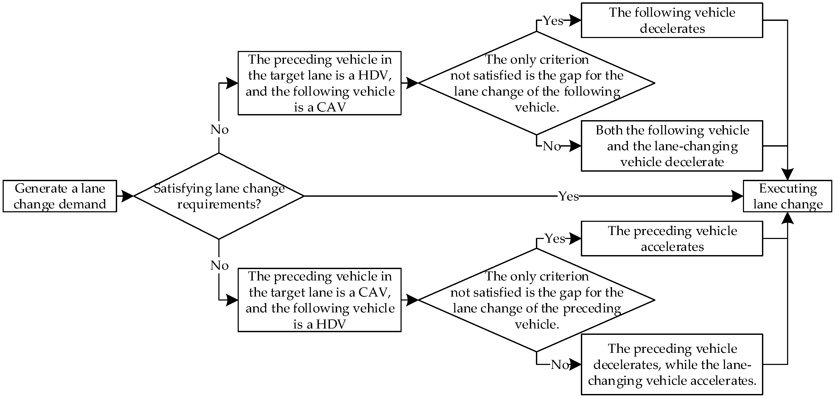
Based on the scenario description, the modeling is limited to situations where the front vehicle in the adjacent lane is an HDV and the rear vehicle is a CAV, as well as scenarios where the front vehicle is a CAV and the rear vehicle is an HDV. When the front vehicle in the adjacent lane is an HDV and the rear vehicle is a CAV, the CAV can perform cooperative deceleration to facilitate the lane-changing vehicle, which may also change lanes by decelerating or maintaining its current state, as illustrated in Figure 4. When the front vehicle in the adjacent lane is a CAV and the rear vehicle is an HDV, the CAV can perform cooperative acceleration, and the lane-changing vehicle may also change lanes by accelerating or maintaining its current state. The specific decision framework for enforced lane changing in this paper is shown in Figure 5.
3. Construction of Lane-Changing Models
Under a DIC dedicated lane management strategy, the lane-changing scenarios for different types of vehicles vary, but all must be conducted under safe gap conditions. This section first presents a safe gap model for vehicle lane changing and then models the autonomous cooperative lane changing and enforced cooperative lane changing for different vehicle types separately.
3.1. Lane-Changing Safety Gap
Vehicles intending to change lanes must ensure that the distances between themselves and the vehicles ahead and behind in the target lane exceed their respective safe following distances. Therefore, the actual gap distance between the leading and following vehicles in the target lane should satisfy Equation (1).
where represents the actual gap distance between the leading and following vehicles in the target lane, denotes the length of the lane-changing vehicle, is the safe distance between the lane-changing vehicle and the leading vehicle in the target lane, and signifies the safe distance between the lane-changing vehicle and the following vehicle in the target lane.
Figure 6 shows a schematic diagram of the safe gap distance during the lane-changing process. As depicted in Figure 6, vehicles A, B, and C represent the positions of the vehicles prior to lane changing, while A’, B’, and C’ represent the positions of the vehicles after the lane-changing maneuver has been completed. Throughout the entire lane-changing process, the vehicle changing lanes must maintain a safe distance between both the leading and following vehicles in the target lane to avoid collisions that could be caused by the lane change.
The values for and are calculated based on the Gipps safety criterion, which ensures that there is sufficient distance for the current vehicle to perform an emergency braking maneuver without colliding with another vehicle [3]. This criterion takes into account the reaction time of the driver, and, in the case of CAVs, this reaction time corresponds to the communication latency involved in information exchange. and can be expressed as follows:
where represents the reaction time of the driver of the following vehicle and also indicates the information exchange and transmission delay time for CAVs; , , and are the speeds of the lane-changing vehicle, the following vehicle in the target lane, and the leading vehicle in the target lane at the initial moment, respectively; and , , and are the maximum deceleration capabilities of the lane-changing vehicle, the following vehicle in the target lane, and the leading vehicle in the target lane, respectively.
3.2. Lane-Changing Model
3.2.1. Autonomous Cooperative Lane-Changing Control Model
Autonomous cooperative lane-changing control for CAVs is a process that determines whether lane-changing maneuvers can be safely executed based on real-time information of the lane-changing vehicle and surrounding traffic. Essentially, it involves adjusting the speeds of vehicles in the target lane to create a safe gap for the lane-changing vehicle. The lane-changing vehicle, having reached its maximum speed in the current lane without achieving its desired speed, maintains its speed during the cooperative lane-changing process. Therefore, the creation of space for the lane change is accomplished by modulating the speeds of both the leading and following vehicles in the target lane to satisfy the conditions for lane changing. The distance required to be generated by the leading vehicle in the target lane, combined with its current distance from the lane-changing vehicle, must be greater than or equal to the safe lane-changing gap. This is determined by the initial speed difference between the leading vehicle and the lane-changing vehicle, the deceleration, and the time, as shown in Equation (4). The same applies to the following vehicle in the target lane, as seen in Equation (5).
where and are the distances required to be generated by the leading and following vehicles in the target lane, respectively; and are the current distances of the lane-changing vehicle from the leading and following vehicles in the target lane, respectively; and are the times required for the leading and following vehicles in the target lane to create a lane-changing space, respectively; and and are the accelerations and decelerations of the leading and following vehicles in the target lane while creating a lane-changing space, respectively.
Due to the fact that successful lane changing is constrained by multiple factors, the process of changing lanes is subject to certain constraints. For the leading vehicle in the target lane, the ability to accelerate and participate in cooperative lane changing is restricted by the vehicle ahead of it. At this time, the distance between the lane changing vehicle and the leading vehicle in the target lane needs to be greater than the safe distance between the two vehicles plus the length of the leading vehicle in the target lane, as shown in Equation (6).
where represents the distance between the lane-changing vehicle and the x-th vehicle ahead and is the minimum safe following distance between vehicle and the vehicle directly in front of it.
The following vehicle in the target lane, unimpeded by the vehicle ahead, may decelerate at any time to satisfy the conditions for lane changing. However, such deceleration can impact the trailing vehicles and even affect vehicles further back in the traffic stream, potentially leading to subsequent vehicles stopping and disrupting the flow of traffic, thereby having a significant impact on the overall traffic flow. Therefore, the deceleration behavior of following vehicles in the cooperative lane-changing process cannot be unrestricted; it is also subject to certain constraints. According to the analysis in reference [25], if the gap remains smaller than 10 m (with the recognized average gap being 10.7 m [25]) after the vehicle ahead accelerates to adjust the lane-changing gap, the following vehicle should not engage in cooperative deceleration.
In addition to the constraints imposed by the leading and following vehicles in the target lane, the vehicle attempting to change lanes is also constrained by road conditions and its own dynamic performance capabilities. When driving on the road, the vehicle’s speed must be within the road’s speed limit and below the maximum speed that the vehicle’s dynamic performance can achieve. The maximum and minimum acceleration of the vehicle also have certain constraints. These constraints can be represented by an equation like the one referred to as Equation (7):
Here, , , and denote the vehicle’s speed, acceleration, and deceleration, respectively; , , and represent the maximum speed limit of the vehicle, the maximum acceleration, and the minimum deceleration, respectively; and and correspond to the maximum and minimum speed limits of the road, respectively.
In summary, the autonomous cooperative lane-changing problem for CAVs is formulated as a problem of solving for the accelerations of the leading and following vehicles in the target lane, where the leading vehicle is to accelerate and the following vehicle is to decelerate. To ensure that the lane-changing maneuver minimizes its impact on the vehicles in the target lane, improves lane-changing efficiency, and avoids abrupt acceleration or deceleration of the vehicles involved in cooperative lane changing, this paper set the objectives of minimizing both the acceleration of the vehicles participating in the cooperative lane change and the time required to complete the lane change. Consequently, a cooperative lane-changing optimization model was developed based on these goals. Since the objectives of minimizing acceleration and reducing lane-changing time are inherently conflicting, the model introduced in this paper incorporates weighting coefficients into the objective function to achieve a balanced and optimal solution between the two goals, as expressed in Equation (8):
Here, and represent the weighting coefficients, with values derived from reference [26], which are, respectively, 0.65 and 0.35.
3.2.2. Mandatory Cooperative Lane-Changing Control Model
- Scenario ①: in the target lane, the leading vehicle is an HDV, followed by a CAV
In this scenario, when only the following vehicle does not satisfy the safe following distance, the lane-changing control method is the same as that described in Equation (5). However, if the gap between the lane-changing vehicle and the vehicle ahead in the target lane does not meet the safe following distance, either the lane-changing vehicle decelerating or the following CAV in the target lane slowing down can create a safe gap for lane changing. The control method for this is as per Equation (9). The following vehicle in the target lane is treated similarly, but the gap distance it needs to create includes the distance generated by the deceleration of the lane-changing vehicle, as shown in Equation (10).
Here, represents the distance that needs to be generated by the lane-changing vehicle, denotes the time required for the lane-changing vehicle to create the lane-changing space, and indicates the deceleration of the lane-changing vehicle while generating the space for the lane change.
- Scenario ②: in the target lane, the leading vehicle is a CAV, followed by an HDV
In this scenario, when only the leading vehicle does not satisfy the safe following distance, the lane-changing control method is the same as that described in Equation (4). However, if the gap between the lane-changing vehicle and the following vehicle in the target lane does not meet the safe distance requirements, the lane-changing vehicle will accelerate or the leading CAV in the target lane will accelerate to create a safe gap for lane changing. The control method for this situation is detailed in Equation (11). The leading vehicle in the target lane is handled in a similar manner, but the distance it needs to create must include the additional distance resulting from the acceleration of the lane-changing vehicle, as indicated in Equation (12).
where denotes the distance that needs to be generated by the lane-changing vehicle, represents the time required for the lane-changing vehicle to create the lane-changing space, and signifies the acceleration of the lane-changing vehicle while generating the space for the lane change.
Based on the aforementioned considerations, the problem of forced cooperative lane changing involving an HDV can be described as the issue of solving for the acceleration of the leading vehicle in the target lane, the deceleration of the following vehicle in the target lane, and the acceleration of the lane-changing vehicle itself. This study aims to minimize vehicle acceleration and lane-changing time, and thus establishes a weighted objective function, as shown in Equation (13):
3.3. Optimization Algorithm
Based on the lane-changing control model, one can obtain a set of acceleration values and corresponding lane-changing time solutions that satisfy the relevant constraints. Then, optimization is carried out using the TOPSIS (Technique for Order Preference by Similarity to Ideal Solution) algorithm proposed in reference [27]. TOPSIS can make full use of the information in the original data, and its results can accurately reflect the differences between various schemes. The specific steps of the TOPSIS algorithm are as follows:
Step 1: Data normalization
During the lane-changing process, both acceleration and lane-changing time are considered to be better when they are smaller, making them minimization indicators. Equation (14) is used to convert these into maximization indicators:
where represents the specific value of each indicator, is the converted maximization indicator, and represents the maximum value that the variable can take. The normalized matrix is obtained as follows:
Step 2: Data Standardization
To eliminate the influence of different units of measurement, the normalized matrix is subjected to standardization. The standardized matrix is denoted as Z, and each element within it is calculated as follows:
Consequently, the standardized matrix, Z, is obtained after normalization:
Step 3: Optimal Solution
The optimal solution, Z+, is composed of the maximum values in each column in matrix Z:
Step 4: Worst solution
The worst solution, Z−, is constituted by the minimum values in each column in matrix Z:
Step 5: Calculate the Distance to the Optimal and Worst Solutions
The distance to the optimal solution is calculated as follows:
The distance to the worst solution is calculated as follows:
Step 6: Scoring
Each alternative is then scored according to Equation (22):
where and a smaller , indicating a shorter distance to the optimal solution, results in a larger ; similarly, a smaller , denoting a shorter distance to the inferior solution, yields a smaller . Consequently, the closer is to 1, the more favorable the alternative is.
4. Simulation Experiment
To validate the effectiveness of the lane-changing control methods for different types of vehicles under the DIC dedicated lane management strategy proposed in this paper, simulation experiments were conducted using the currently mature microsimulation platform SUMO [22]. The simulation parameters were first set, then simulation scenarios for autonomous cooperative lane changing for CAVs and mandatory cooperative lane changing for HDVs were constructed, and, finally, the simulation results were analyzed.
In the simulation experiments, regarding the car-following models, the default Krauss car-following model in SUMO (Version 1.19.0) was used for HDVs [28], while the CACC model developed by references [29,30,31], among others, was used for CAVs; as for the lane-changing models, the LC2013 lane-changing model within SUMO (Version 1.19.0) was utilized for both CAVs and HDVs [32].
4.1. Simulation Parameter Settings
4.2. Simulation Scenario
- (1)
- Autonomous Cooperative Lane-Changing Simulation Scenario for CAVs
Figure 7 schematically presents the simulation environment for the autonomous cooperative lane change of CAVs. Here, the red vehicle signifies a CAV traveling in a regular lane and preparing to change lanes. There is a continuous flow of CAV traffic in the target dedicated lane. The road speed limit is set at 33.3 m/s. Prior to initiating the lane change, all vehicles cruise at a constant speed of 27 m/s, according to a car-following model, in order to simulate a scenario of steady traffic flow.
To test the effectiveness of the lane-changing control model under various traffic conditions, this paper dynamically adjusted three key parameters: “the time headway between vehicles in the target lane”, “the speed difference between the lane-changing vehicle and vehicles in the target lane”, and “the initial distance difference between the lane-changing vehicle and the lead vehicle in the target lane.”
Specifically, the time headway between vehicles in the target lane was set to vary from 1 s to 2 s, with increments of 0.1 s. The speed difference between the lane-changing vehicle and vehicles in the target lane ranged from −5 m/s to 0 m/s, with increments of 1 m/s. The initial distance difference between the lane-changing vehicle and the lead vehicle in the target lane ranged from 10% to 90%, with increments of 10%. By combining these parameters, a total of 11 × 6 × 9 = 594 different scenarios were generated and compared with traditional lane-changing models to verify the efficiency of the model proposed in this paper.
- (2)
- Mandatory Cooperative Lane-Changing Simulation Scenario for HDV
Figure 8 illustrates the simulation scenario for the mandatory cooperative lane change of HDVs. In this figure, the red vehicle represents an HDV, while the green vehicles represents a CAV. It is important to note that the HDV is allowed to travel in the DIC lane when it is not within the clear distance of a CAV. In this scenario, the upper lane in the figure is designated as the DIC lane, and the other lane is a regular lane, both having a speed limit of 33.3 m/s. A DIC lane is more suited for scenarios with low CAV penetration and low traffic demand; hence, the traffic demand was set at 2500 veh/h, 3000 veh/h, and 3500 veh/h, with a CAV penetration rate of 30% for the simulation. The simulation ran for 3800 s, and the first 100 s and the last 100 s were discarded to maintain a continuous flow within the scenario.
During the simulation process, vehicles were inserted into the road network at equal intervals, and the car-following model was utilized to control them to maintain a safe distance from the leading vehicle. Moreover, in the simulation, vehicles were loaded by setting the number of vehicles per hour to ensure that the required traffic demand was achieved.
4.3. Discussion of Results
- (1)
- Simulation results for CAV autonomous cooperative lane change
Next, we conducted a comparative analysis of the control efficiency between the cooperative lane-changing model and the traditional lane-changing model from two perspectives: the success rate of lane changes and the impact of lane changes on vehicles participating in cooperation. This analysis aimed to validate the efficiency of autonomous cooperative lane-changing control in CAVs.
- (a)
- Lane-change Success Rate
In Table 3, we have listed the simulation statistical results for the lane-changing success rate under two categories of lane-changing models. Compared to traditional lane-changing control, the success rate of lane changes increased from 79.97% to 88.22%, an increase of 8.25%. This indicates that cooperative collaboration among CAVs can effectively improve the success rate of vehicle lane changes.
We further analyzed the relationship between the aforementioned three key parameters and the lane-changing success rate to clarify the impact of different factors on the success rate of lane changes, as depicted in Figure 9.
As shown in Figure 9a, the lane-changing success rate for both control models shows a gradual increasing trend with the rise in the driving times of vehicles in the target lane. This is because, as the distance between adjacent vehicles in the target lane increases, the vehicle attempting to change lanes has more maneuvering space, thereby increasing the likelihood of a successful lane change.
In Figure 9b, the differences in the distance between the lane-changing vehicle and the preceding vehicle in the target lane and the lane-changing success rate demonstrate a trend that first increases and then decreases. The rationale is that when the distance difference is small, the lane-changing vehicle is too close to the preceding vehicle in the target lane and is unable to maintain a safe gap for lane changing. It is therefore necessary to reduce the speed of the lane-changing vehicle to create a larger gap. Cooperative lane changing can adjust the acceleration of the preceding vehicle in the target lane simultaneously, thus achieving a higher success rate than traditional lane changing. When the distance difference is large, the willingness of the following vehicle in the target lane to decelerate and cooperate is not strong, and more lane-changing vehicles will opt for other gaps that appear later, leading to lane-changing failure. With the cooperative lane-changing model, when there is a large distance difference and the gap between the lane-changing vehicle and the preceding vehicle in the target lane already satisfies the safety distance, like the traditional model, it only needs to adjust the speed of the following vehicle in the target lane; hence, the performance is generally consistent with traditional lane changing.
Figure 9c reflects the relationship between the speed difference between the lane-changing vehicle and the preceding vehicle in the target lane and the lane-changing success rate. When the speed difference is zero, due to the close proximity of the preceding vehicle in the target lane, the lane-changing vehicle cannot create a lane-changing gap by decelerating, resulting in a lower success rate. However, under any circumstance, the success rate of cooperative lane-changing control is always higher than that of traditional lane-changing control. This advantage is clearly due to the ability of the preceding vehicle in the target lane to actively accelerate and provide a larger space for the lane-changing vehicle under cooperative lane-changing control.
The analysis presented above indicates that the cooperative lane-changing control model proposed in this paper can enhance the vehicle lane-changing success rate to a certain extent.
- (b)
- The impact on vehicles participating in cooperative lane changing
To facilitate a more vivid and detailed comparison of the performance of the two types of lane-changing models, this research selected a specific scenario for comparative analysis. The parameters for the chosen scenario are detailed in Table 4, and the simulation results are illustrated in Figure 10.
Figure 10 schematically illustrates the impact of lane-changing behavior on the following vehicles in the target lane. Compared to traditional lane-changing control, cooperative lane changing has a smaller impact on the following vehicle’s speed and allows it to return to normal speed more quickly. Under traditional lane-changing control, the preceding vehicle in the target lane is not affected by the lane-changing maneuver and continues to travel at its original speed; however, during cooperative lane-changing control, the preceding vehicle in the target lane may actively accelerate to coordinate with the lane-changing vehicle, thus more quickly creating a safe gap for lane changing.
Therefore, compared to traditional lane-changing control, the time taken to change lanes with cooperative lane-changing control is reduced from 45 s to 39 s. Additionally, the duration of speed fluctuations caused by the lane change is also reduced from 17 s to 11 s. This demonstrates that the cooperative lane-changing control model can achieve more efficient lane-changing operations under the same conditions.
- (2)
- Simulation results for HDV mandatory cooperative lane change
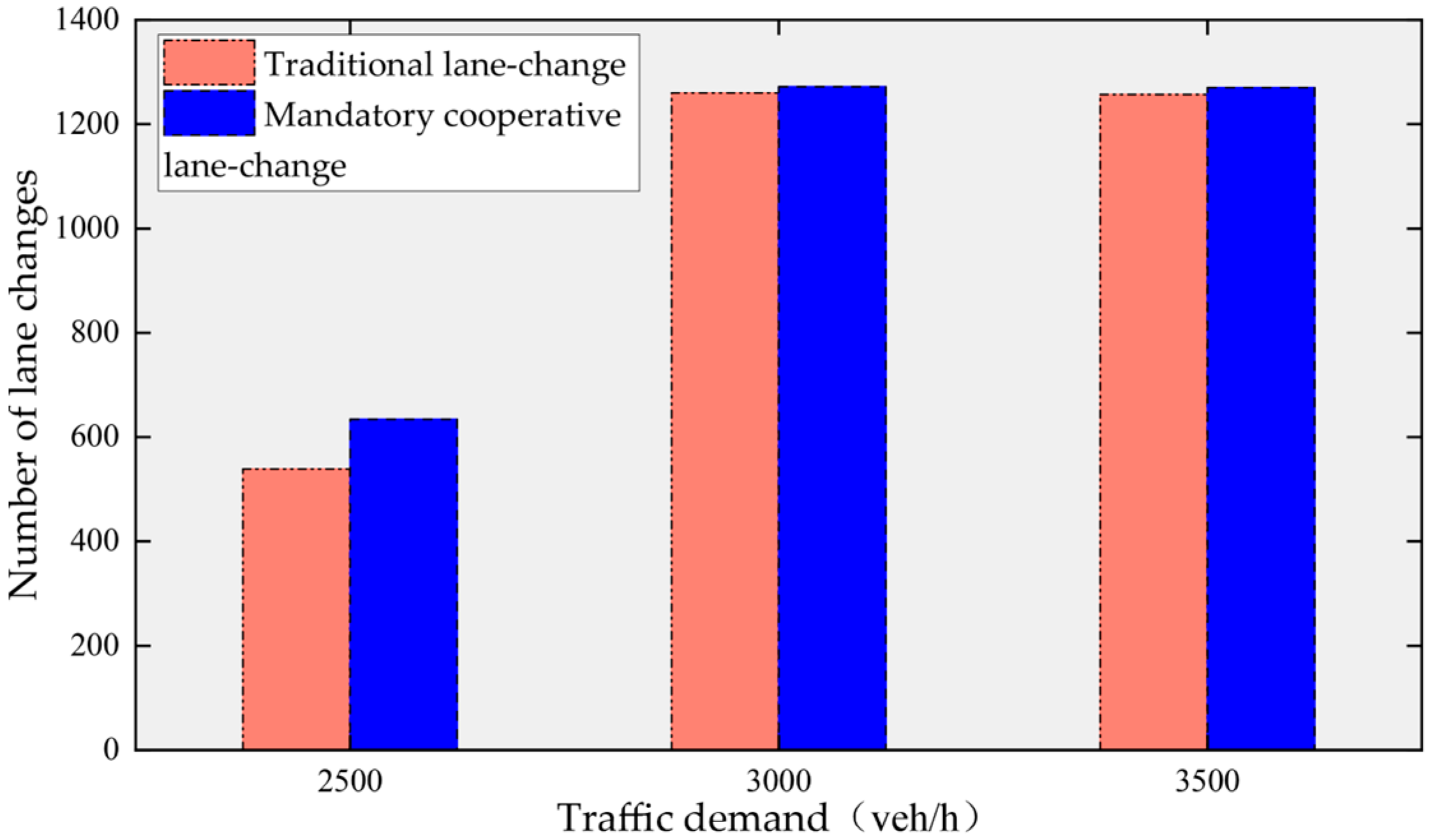
To validate the effectiveness of the HDV mandatory cooperative lane-changing model, we selected indicators such as average travel time, average speed, number of vehicles passed, and number of lane changes for comparative analysis. The simulation results are presented in Table 5 and show that compared to the traditional lane-changing model, the mandatory cooperative lane-changing model has achieved improvements in all indicators to a certain extent.
In the comparison of the number of vehicles passed, when the traffic demand is set to 2500 veh/h, both lane-changing models facilitate the passage of exactly 2500 vehicles, demonstrating that, at this juncture, DIC dedicated lane management strategies are capable of satisfying road traffic demands. Nevertheless, as traffic demand escalates, for instance, to 3000 veh/h, the number of vehicles processed by the traditional lane-changing model is 2954, whereas the mandatory cooperative lane-change model sees an increment to 2992 vehicles, an augmentation of 38 vehicles, thereby more closely aligning with the established road traffic demand. This improvement is credited to the cooperative nature of the mandatory cooperative lane-change model, which diminishes the disruptive impact of vehicle lane changes on the flow of traffic, consequently elevating the volume of traffic flow. In a similar vein, in simulation scenarios with a traffic demand of 3500 veh/h, the mandatory cooperative lane-change model also achieves an increase in the number of vehicles passing through the road.
The results for the other three evaluation metrics are depicted in Figure 11, Figure 12 and Figure 13:
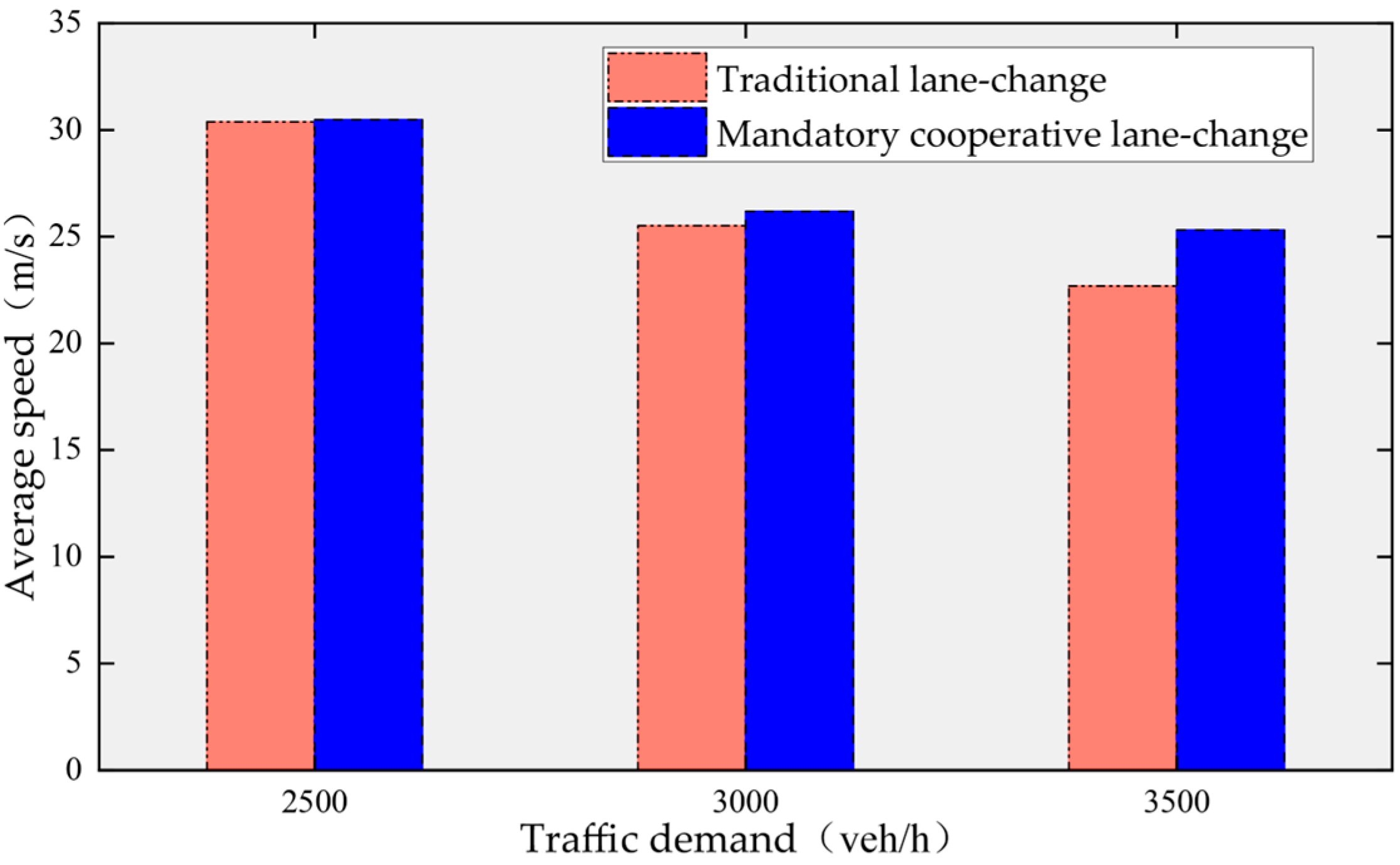
As depicted in Figure 11, with an increase in traffic demand, the travel time required by vehicles also rises. Under various traffic demand conditions, the mandatory cooperative lane-change model consistently requires less travel time than the traditional lane-changing model, with the improvement being more pronounced as the traffic demand increases. Conversely, as traffic demand grows, the average speed of vehicles tends to decrease, as shown in Figure 12. However, the speeds achieved by the mandatory cooperative lane-change model are consistently higher than those of the traditional lane-changing model. This occurs because the cooperative nature of the model allows vehicles to choose the optimal speed-change strategy, thus avoiding speed losses.
Figure 13 illustrates the variations in the number of vehicle lane changes. Under various traffic demands, the mandatory lane-change cooperation model consistently enhances the success rate of lane changes, allowing a greater number of HDVs to exit from the DIC dedicated lanes. This improvement facilitates a superior driving environment for CAVs, thereby achieving the effect of prioritized traffic flow.
5. Conclusions
This paper investigates the issues of CAV autonomous cooperative lane change and HDV mandatory cooperative lane change under a DIC dedicated lane strategy. Based on the theory of safe distances and considering the influence of upstream and downstream vehicles in the target lane, lane-changing decision-control models were constructed using multi-objective optimization, and multi-vehicle collaborative lane-changing methods were designed. The efficiency of the models was validated through SUMO simulation experiments, and the conclusions are as follows:
- (1)
- In scenarios of CAV autonomous cooperative lane change, compared with traditional lane-changing models, the autonomous cooperative lane-change model exhibits superior performance in enhancing the success rate of lane changes, reducing lane-changing time, diminishing the impact on the speed of surrounding vehicles, and more quickly restoring a stable driving state.
- (2)
- In scenarios of HDV mandatory cooperative lane change, compared with traditional lane-changing models, the mandatory cooperative lane-change model demonstrates better control efficiency in reducing vehicle travel time, increasing vehicle speed, increasing the number of vehicles passing through the road, and improving the success rate of lane changes.
- (3)
- The results from the study of CAV autonomous cooperative lane change and HDV mandatory cooperative lane change suggest that under the management strategy of DIC dedicated lanes, by facilitating multi-vehicle collaborative lane changes, the efficiency of lane changing can be improved and the stop-and-go waves caused by lane changing in traffic flow can be reduced. Providing dedicated lanes for CAVs can significantly enhance road traffic efficiency while avoiding the waste of road resources.
Due to the constraints of the paper’s length, there are still some areas that this research has not covered, such as lateral trajectory planning during vehicle lane changing, collaborative merging control in the ramp merging area under the strategy of DIC dedicated lanes on freeways, and vehicular communication issues. These will constitute the directions of our future research.
Author Contributions
Conceptualization, Methodology, Investigation, Writing—original draft preparation, Formal analysis, J.X.; Writing—review and editing, Supervision, Project administration, Funding acquisition, Z.W.; Formal analysis, Visualization, Software, Validation, Q.M.; Software, Review, Q.W.; Review, Funding acquisition, Z.X. All authors have read and agreed to the published version of the manuscript.
Funding
This research was funded by the National Natural Science Foundation of China (grant nos. 52372296 and 52102406), the Natural Science Foundation of Hunan Province (no. 2023JJ30039), the Postgraduate Scientific Research Innovation Project of Hunan Province (nos. CX20220862 and CX20230856), the Changsha Science and Technology Major Special Project (no. kh2301004), and the Open Fund of the National Engineering Research Center of Highway Maintenance Technology (Changsha University of Science and Technology) (no. kfj220108).
Informed Consent Statement
Informed consent has been obtained from all authors and funders involved in the study, and each author has agreed to and decided on the publication of this paper.
Data Availability Statement
Data are contained within the article.
Conflicts of Interest
The authors declare no conflicts of interest.
References
- Ma, C.; Li, D. A review of vehicle lane-change research. Phys. A Stat. Mech. Its Appl. 2023, 18, 129060. [Google Scholar] [CrossRef]
- Yang, D.; Lv, M.; Dai, L.Y.; Wang, X.W.; Guo, X. Lane Selection Decision Model for Autonomous Vehicles in the Connected Vehicle Environment. China J. Highw. Transp. 2022, 35, 243–255. [Google Scholar] [CrossRef]
- Gipps, P.G. A model for the structure of lane-changing decisions. Transp. Res. Part B Methodol. 1986, 20, 403–414. [Google Scholar] [CrossRef]
- Yang, Q.I.; Koutsopoulos, H.N. A microscopic traffic simulator for evaluation of dynamic traffic management systems. Transp. Res. Part C Emerg. Technol. 1996, 4, 113–129. [Google Scholar] [CrossRef]
- Halati, A.; Lieu, H.; Walker, S. CORSIM-Corridor Traffic Simulation Model. Traffic Congestion and Traffic Safety in the 21st Century: Challenges, Innovations, and Opportunities Urban Transportation Division, ASCE; Highway Division, ASCE; Federal Highway Administration, USDOT; and National Highway Traffic Safety Administration, USDOT. 1997. Available online: http://worldcat.org/isbn/0784402434 (accessed on 21 March 2024).
- Yang, M.; Wang, X.; Quddus, M. Examining lane-change gap acceptance, duration and impact using naturalistic driving data. Transp. Res. Part C Emerg. Technol. 2019, 104, 317–331. [Google Scholar] [CrossRef]
- Liu, Y.; Zhou, B.; Wang, X.; Li, L.; Cheng, S.; Chen, Z.; Li, G.; Zhang, L. Dynamic lane-changing trajectory planning for autonomous vehicles based on discrete global trajectory. IEEE Trans. Intell. Transp. Syst. 2021, 23, 8513–8527. [Google Scholar] [CrossRef]
- Kesting, A.; Treiber, M.; Helbing, D. General lane-changing model MOBIL for car-following models. Transp. Res. Rec. 2007, 1999, 86–94. [Google Scholar] [CrossRef]
- Yang, J.S.; Wang, P.W.; Gao, S.; Zhang, M.; Wei, X.P.; Zhang, Y.L. Research on Support Vector Machine-Based Vehicle Lane-change Decision Model. J. Shandong Univ. Technol. (Nat. Sci. Ed.) 2023, 37, 66–72. [Google Scholar] [CrossRef]
- Zhao, S.E.; Ke, T.; Liu, P. Research on Vehicle Lane-change Decision Model Based on Bayesian Networks. J. Chongqing Jiaotong Univ. (Nat. Sci.) 2020, 39, 130–137+144. [Google Scholar] [CrossRef]
- Kamrani, M.; Srinivasan, A.R.; Chakraborty, S.; Khattak, A.J. Applying Markov decision process to understand driving decisions using basic safety messages data. Transp. Res. Part C Emerg. Technol. 2020, 115, 102642. [Google Scholar] [CrossRef]
- Zhao, J.D.; Zhao, Z.M.; Qu, Y.C.; Xie, D.F.; Sun, H.J. Research on Trajectory Data-Driven Vehicle Lane-change Intent Recognition. J. Transp. Syst. Eng. Inf. Technol. 2022, 22, 63–71. [Google Scholar] [CrossRef]
- Shi, Q.; Zhang, H. An improved learning-based LSTM approach for lane-change intention prediction subject to imbalanced data. Transp. Res. Part C Emerg. Technol. 2021, 133, 103414. [Google Scholar] [CrossRef]
- Zhang, H.; Du, L.; Shen, J. Hybrid MPC system for platoon based cooperative lane-change control using machine learning aided distributed optimization. Transp. Res. Part B Methodol. 2022, 159, 104–142. [Google Scholar] [CrossRef]
- Kawabata, K.; Ma, L.; Xue, J.; Zhu, C.; Zheng, N. A path generation for automated vehicle based on Bezier curve and via-points. Robot. Auton. Syst. 2015, 74, 243–252. [Google Scholar] [CrossRef]
- Xie, D.F.; Fang, Z.Z.; Jia, B.; He, Z. A data-driven lane-changing model based on deep learning. Transp. Res. Part C Emerg. Technol. 2019, 106, 41–60. [Google Scholar] [CrossRef]
- Yu, Y.; Luo, X.; Su, Q.; Peng, W. A dynamic lane-changing decision and trajectory planning model of autonomous vehicles under mixed autonomous vehicle and human-driven vehicle environment. Phys. A Stat. Mech. Its Appl. 2023, 609, 128361. [Google Scholar] [CrossRef]
- Fu, M.; Li, S.; Guo, M.; Yang, Z.; Sun, Y.; Qiu, C.; Wang, X.; Li, X. Cooperative decision-making of multiple autonomous vehicles in a connected mixed traffic environment: A coalition game-based model. Transp. Res. Part C Emerg. Technol. 2023, 157, 104415. [Google Scholar] [CrossRef]
- Ji, A.; Ramezani, M.; Levinson, D. Pricing lane-changes. Transp. Res. Part C Emerg. Technol. 2023, 149, 104062. [Google Scholar] [CrossRef]
- Monteiro, F.V.; Ioannou, P. Safe autonomous lane-changes and impact on traffic flow in a connected vehicle environment. Transp. Res. Part C Emerg. Technol. 2023, 151, 104138. [Google Scholar] [CrossRef]
- Liu, Y.; Wang, H.; Dong, C.; Chen, Y. A centralized relaxation strategy for cooperative lane-change in a connected environment. Phys. A Stat. Mech. Its Appl. 2023, 624, 128934. [Google Scholar] [CrossRef]
- Wang, Z.; Mi, Q.; Xiang, J.; Zhang, Z.L.; Tang, J.J. An evaluation of lane management strategy for CAV priority in mixed traffic. IET Intell. Transp. Syst. 2024, 18, 467–479. [Google Scholar] [CrossRef]
- Sha, H.; Singh, M.K.; Haouari, R.; Papazikou, E. Network-wide safety impacts of dedicated lanes for connected and autonomous vehicles. Accid. Anal. Prev. 2024, 195, 107424. [Google Scholar] [CrossRef] [PubMed]
- Wu, W.; Head, L.; Yan, S.; Ma, W. Development and evaluation of bus lanes with intermittent and dynamic priority in connected vehicle environment. J. Intell. Transp. Syst. 2018, 22, 301–310. [Google Scholar] [CrossRef]
- Li, P.F.; Shi, J.J.; Liu, X.M. Analysis of Competitive and Cooperative Lane Changing Behavior Characteristics on Urban Expressways. J. Highw. Transp. Dev. 2016, 33, 130–139. [Google Scholar]
- Ma, J.; Li, X.; Zhou, F.; Hu, J.; Park, B.B. Parsimonious shooting heuristic for trajectory design of connected automated traffic part II: Computational issues and optimization. Transp. Res. Part B Methodol. 2017, 95, 421–441. [Google Scholar] [CrossRef]
- Zhan, H.; Wang, G.; Shan, X.; Liu, Y. Risk-aware lane-change trajectory planning with rollover prevention for autonomous light trucks on curved roads. Mech. Syst. Signal Process. 2024, 211, 111126. [Google Scholar] [CrossRef]
- Cui, J.F.; Hu, B.X.; Xia, H.; Chen, H.; Chen, X.G. Simulation and Comparative Analysis of Multiple Vehicle Platoon Models in the SUMO Platform. J. Chongqing Univ. 2021, 44, 43–54+98. [Google Scholar] [CrossRef]
- Milanés, V.; Shladover, S.E. Modeling cooperative and autonomous adaptive cruise control dynamic responses using experimental data. Transp. Res. Part C Emerg. Technol. 2014, 48, 285–300. [Google Scholar] [CrossRef]
- Xiao, L.; Wang, M.; Arem, B.V. Realistic Car-Following Models for Microscopic Simulation of Adaptive and Cooperative Adaptive Cruise Control Vehicles. Transp. Res. Rec. J. Transp. Res. Board 2017, 2623, 1–9. [Google Scholar] [CrossRef]
- Xiao, L.; Wang, M.; Schakel, W.; Arem, B. Unravelling effects of cooperative adaptive cruise control deactivation on traffic flow characteristics at merging bottlenecks. Transp. Res. Part C Emerg. Technol. 2018, 96, 380–397. [Google Scholar] [CrossRef]
- Erdmann, J. SUMO’s lane-changing model. In Proceedings of the Modeling Mobility with Open Data: 2nd SUMO Conference 2014, Berlin, Germany, 15–16 May 2014; Springer International Publishing: Berlin/Heidelberg, Germany, 2015; pp. 105–123. [Google Scholar] [CrossRef]
Figure 1.
Schematic diagram of lane change to a DIC dedicated lane.
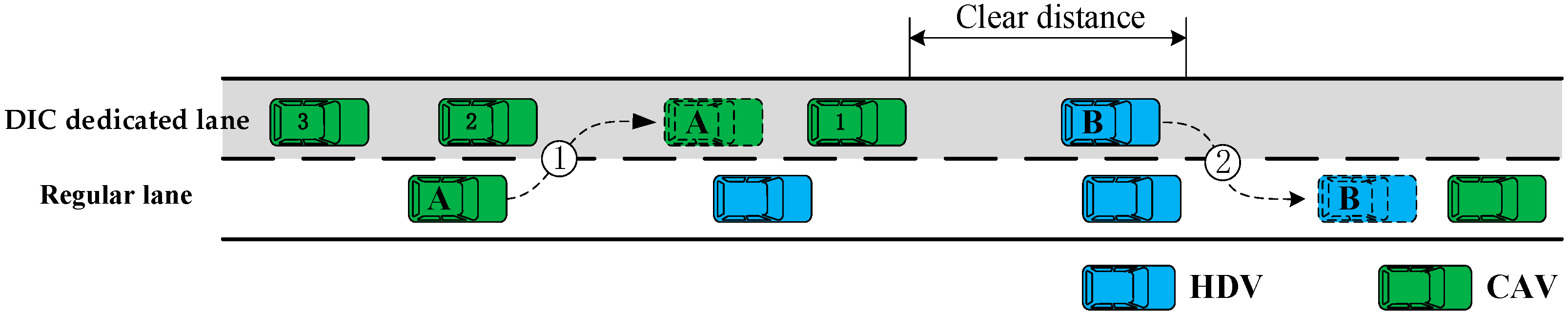
Figure 2.
Schematic diagram of CAV autonomous cooperative lane change, before and after.
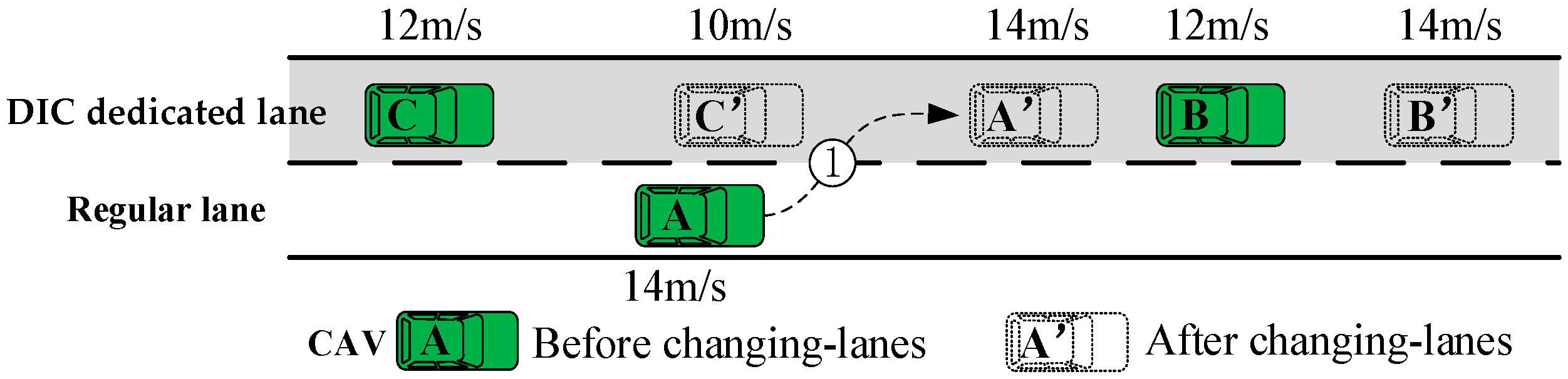
Figure 3.
Autonomous cooperative lane-change decision framework.
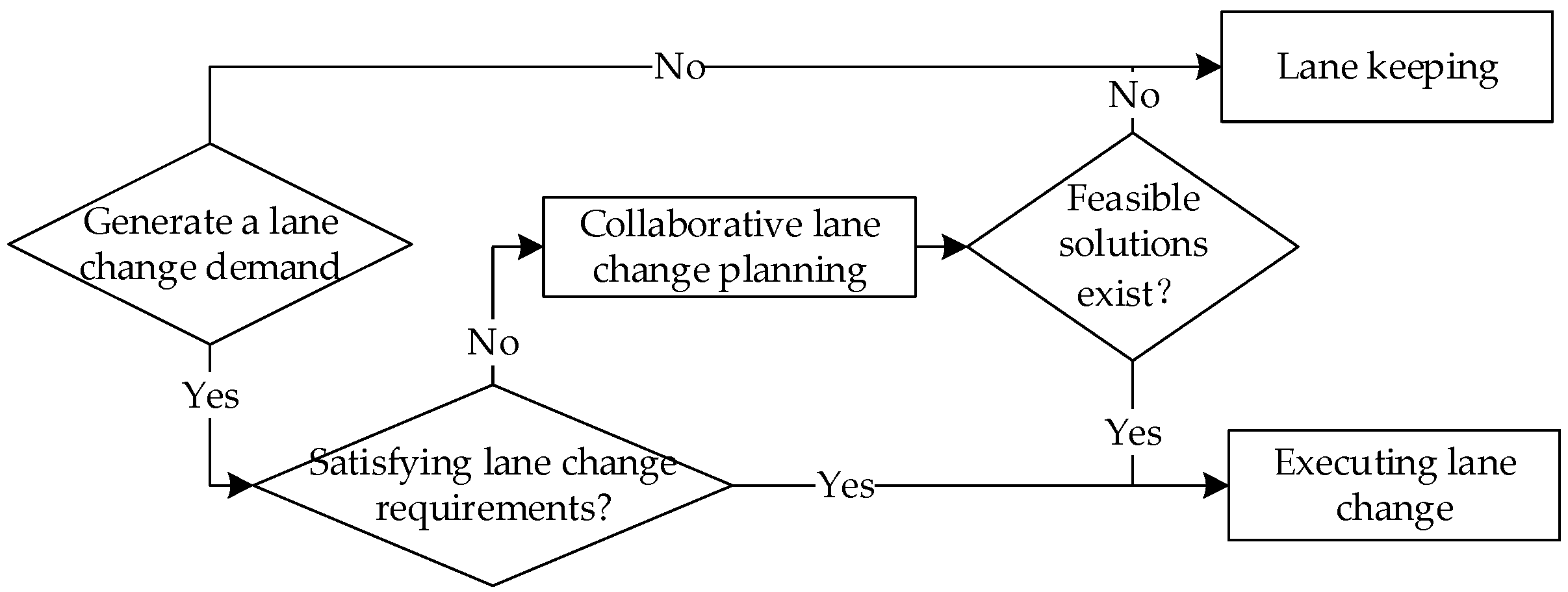
Figure 4.
Schematic diagram of HDV mandatory cooperative lane change, before and after (illustrated with Scenario ①).
Figure 4.
Schematic diagram of HDV mandatory cooperative lane change, before and after (illustrated with Scenario ①).

Figure 5.
Mandatory lane-change decision framework.

Figure 6.
Illustration of safety gap.

Figure 7.
Illustration of cooperative simulation scenario for autonomous lane change.

Figure 8.
Illustration of cooperative simulation scenario for forced lane change.

Figure 9.
Relationship between different parameters and lane-change success rate. (a) The headway between adjacent vehicles in the target lane. (b) The initial distance difference between the changing vehicle and the lead vehicle in the target lane. (c) The speed difference between the changing vehicle and the vehicles in the target lane.

Figure 10.
Speed curve variation of different lane-change control models in specific scenarios. (a) Speed curve of the traditional lane-change model. (b) Speed curve of the cooperative lane-change model.
Figure 10.
Speed curve variation of different lane-change control models in specific scenarios. (a) Speed curve of the traditional lane-change model. (b) Speed curve of the cooperative lane-change model.

Figure 11.
Travel time comparison.
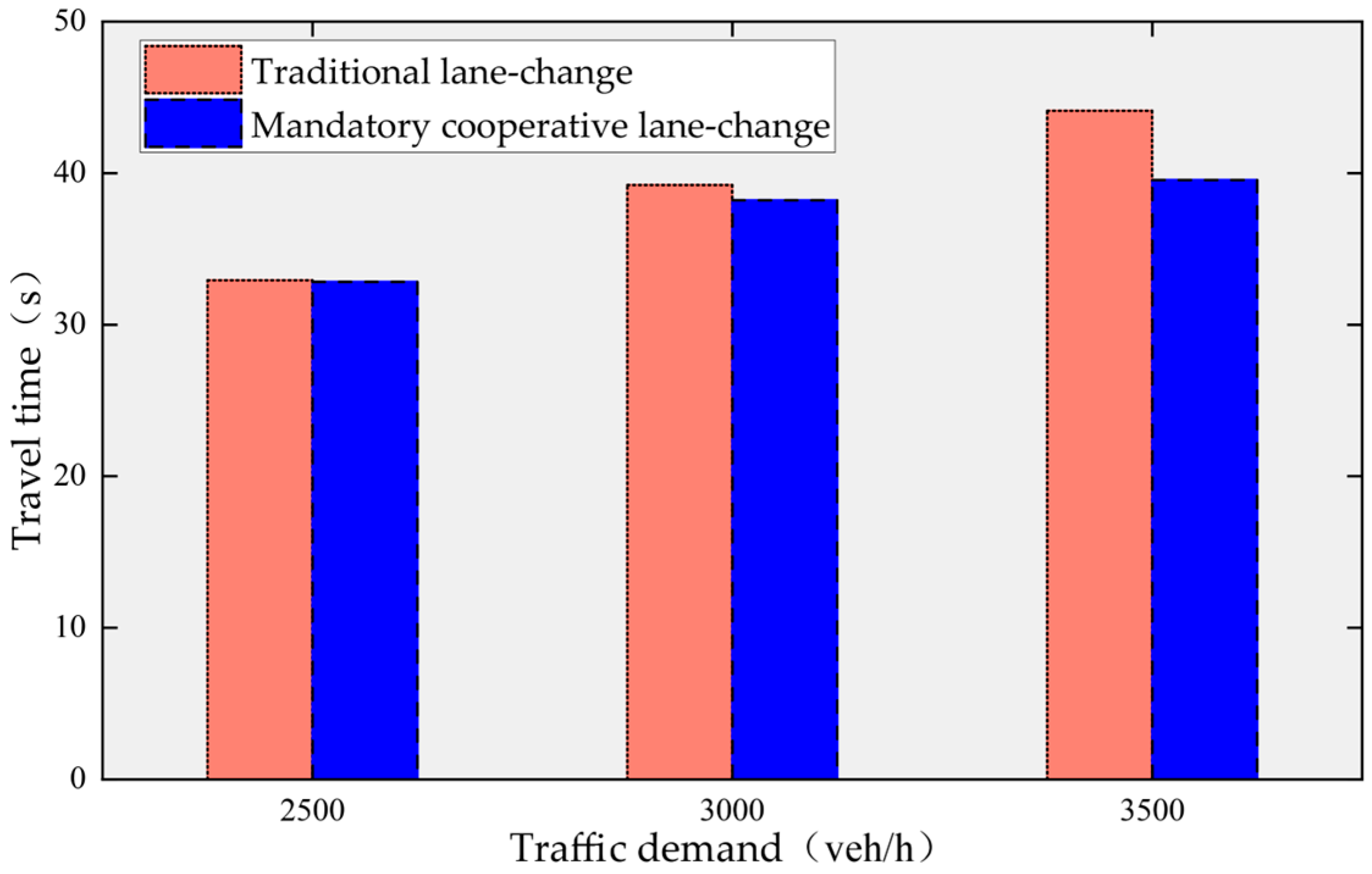
Figure 12.
Speed comparison.

Figure 13.
Comparison of lane-change counts.

Table 1.
Vehicle parameter settings.
| Parameters | Symbols | Values | Units |
|---|---|---|---|
| Length | L | 5 | m |
| Width | W | 1.8 | m |
| Height | H | 1.5 | m |
| Acceleration | a | 2.6 | m/s2 |
| Deceleration | b | 4.5 | m/s2 |
| Emergency Deceleration | be | 9 | m/s2 |
Table 2.
Simulation parameter settings.
| Parameters | Symbols | Values | Units |
|---|---|---|---|
| Headway (CAV) | tau | 0.6 | s |
| Headway (HDV) | tau | 1.4 | s |
| Simulation Time Step | - | 0.1 | s |
| Response Time (CAV) | 0.1 | s | |
| Response Time (HDV) | 1 | s | |
| Velocity Deviation (CAV) | speedDev | 0 | - |
| Velocity Deviation (HDV) | speedDev | 0.1 | - |
Table 3.
Comparison of lane-change success rates for different lane-change models.
| Lane-Change Model | Number of Successful Lane Changes | Lane-Change Success Rate |
|---|---|---|
| Traditional Lane-Change Model | 475 | 79.97% |
| Cooperative Lane-Change Model | 524 | 88.22% |
Table 4.
Values of specific scenario parameters.
| Parameters | Values |
|---|---|
| Headway between adjacent vehicles in the target lane | 1.3 |
| Initial distance difference between the changing vehicle and the lead vehicle in the target lane | 20% |
| Speed difference between the changing vehicle and the vehicles in the target lane | 1 |
Table 5.
Simulation results of forced cooperative lane change in the synchronized scenario.
| Traffic Volume (veh/h) | Lane-Change Model | Average Travel Time (s) | Average Speed (m/s) | Throughput (veh) | Number of Lane Changes |
|---|---|---|---|---|---|
| 2500 | Traditional lane-change model | 32.93 | 30.37 | 2500 | 539 |
| Forced cooperative lane-change model | 32.82 | 30.47 | 2500 | 634 | |
| 3000 | Traditional lane-change model | 39.21 | 25.51 | 2954 | 1260 |
| Forced cooperative lane-change model | 38.21 | 26.18 | 2992 | 1272 | |
| 3500 | Traditional lane-change model | 44.11 | 22.68 | 2913 | 1257 |
| Forced cooperative lane-change model | 39.55 | 25.3 | 3016 | 1270 |
Disclaimer/Publisher’s Note: The statements, opinions and data contained in all publications are solely those of the individual author(s) and contributor(s) and not of MDPI and/or the editor(s). MDPI and/or the editor(s) disclaim responsibility for any injury to people or property resulting from any ideas, methods, instructions or products referred to in the content. |
© 2024 by the authors. Licensee MDPI, Basel, Switzerland. This article is an open access article distributed under the terms and conditions of the Creative Commons Attribution (CC BY) license (https://creativecommons.org/licenses/by/4.0/).
Share and Cite
MDPI and ACS Style
Xiang, J.; Wang, Z.; Mi, Q.; Wen, Q.; Xu, Z. Cooperative Lane-Change Control Method for Freeways Considering Dynamic Intelligent Connected Dedicated Lanes. Electronics 2024, 13, 1625. https://doi.org/10.3390/electronics13091625
AMA Style
Xiang J, Wang Z, Mi Q, Wen Q, Xu Z. Cooperative Lane-Change Control Method for Freeways Considering Dynamic Intelligent Connected Dedicated Lanes. Electronics. 2024; 13(9):1625. https://doi.org/10.3390/electronics13091625
Chicago/Turabian StyleXiang, Jian, Zhengwu Wang, Qi Mi, Qiang Wen, and Zhuye Xu. 2024. "Cooperative Lane-Change Control Method for Freeways Considering Dynamic Intelligent Connected Dedicated Lanes" Electronics 13, no. 9: 1625. https://doi.org/10.3390/electronics13091625
Note that from the first issue of 2016, this journal uses article numbers instead of page numbers. See further details here.