1. Introduction
Video microsatellites offer continuous target observation, which, coupled with short development cycles and low costs, makes microsatellites widely applicable. in real-time target tracking, environmental monitoring, and other fields. Gaze tracking of targets is a primary operational mode for video microsatellites [
1,
2]. Especially for targets with unknown positions, it is necessary to use high-resolution cameras to image them and use image information to achieve continuous gaze tracking. However, for high-precision target gaze under high resolution and a narrow field of view, the attitude control precision of microsatellites has strict requirements. Furthermore, given that video microsatellites operate in low Earth orbit, external disturbances significantly influence the satellite [
3]. In addition, the internal actuation mechanism within the satellite is subject to interference from frictional forces [
4], and the satellite’s moment of inertia may also vary over time [
5]. This is particularly the case for microsatellites, which feature a relatively low moment of inertia. These factors substantially impact the attitude control precision of microsatellites, sometimes leading to spacecraft control failures [
6]. Overcoming the effects of these disturbances is a major challenge in satellite attitude tracking control.
Currently, two main approaches address the impact of disturbances on spacecraft attitude control [
7,
8,
9,
10]. The first one compensates for disturbance torques through precise modeling or by establishing observers. For instance, a method based on event-triggered anti-disturbance attitude control [
11] addressed the rigid spacecraft facing attitude control challenges under multiple disturbances. This method categorizes disturbances into uncertain model disturbances and norm-bounded equivalent disturbances. It designs a disturbance observer to estimate the disturbances, ensuring the convergence of the attitude control system to a small invariant set. In [
12], the authors proposed a composite attitude stabilization scheme for spacecraft based on dual disturbance observers and high-precision nonsingular terminal sliding mode control. This scheme considers flywheel dynamics and multiple disturbances, compensating for estimated disturbances and mitigating the impact of estimation errors through a composite nonsingular terminal sliding mode attitude controller. It should be noted that existing external disturbance observers often assume that external disturbances remain constant or change slowly. Thus, in [
13], a new disturbance observer was designed to ensure the convergence of attitude and angular velocity to a small range under arbitrary disturbance conditions.
The second approach involves designing robust controllers with superior performance and achieving attitude control while sacrificing a certain degree of precision. Among various control algorithms, sliding mode variable structure control is a typical robust control algorithm. However, the robustness of sliding mode variable structure control relies on the controller continuously changing structures near zero, leading to the chattering problem. Hence, to reduce chattering, scholars worldwide have proposed various methods, such as the boundary layer method [
14], high-order sliding mode control [
15,
16], and control methods based on the convergence law [
17,
18,
19,
20,
21,
22]. In [
23], a spacecraft attitude-tracking control problem was studied using an adaptive integral sliding mode fault-tolerant control strategy. Furthermore, incorporating adaptive laws, a modified fault-tolerant control scheme was proposed to compensate for actuator faults and system uncertainties, including external disturbances and inertia uncertainties. In [
24], the authors combined integral sliding mode with an adaptive law based on barrier functions to address external disturbances and inertia uncertainties a rigid spacecraft faces. This method suppresses disturbances and inertia uncertainties while ensuring the rigid spacecraft system is initially near the sliding mode surface, enhancing system robustness. In [
25], by incorporating a barrier Lyapunov function (BLF) into the dynamic surface technique, a coordinate-free integral sliding mode controller is developed that cannot only deal with the state constraint but also enforce the tracking error converge into the vicinity of the origin. In [
26], a novel, fast nonsingular integral sliding mode control method is proposed to perform the attitude tracking function of spacecraft. A sliding mode control law was established for the high-inertia appendages to maintain an appropriate angular velocity during rotation.
This paper synthesizes the above two approaches and proposes an adaptive integral sliding mode controller with a feedforward compensation disturbance observer. Specifically, a disturbance observer was designed to estimate the friction torque for the flywheel’s frictional disturbance torque. Disturbance compensation for the friction torque was achieved through feedforward control, reducing the upper bound of total disturbances. Secondly, an adaptive integral sliding mode controller was developed for external, uncertain disturbances. The adaptive law adjusts the switching gain according to the magnitude of disturbances, reducing the chattering amplitude of the control torque.
The remainder of this paper is organized as follows:
Section 2 presents the calculation method for the desired attitude of target tracking based on image feedback and describes the reaction wheel and microsatellite attitude models.
Section 3 derives the feedforward compensation disturbance observer and the adaptive integral sliding mode variable structure controller.
Section 4 introduces the simulation experiments and analysis, while
Section 5 concludes this work.
2. Attitude Control System Model
2.1. Calculation of Desired Attitude for Target Tracking Based on Image Feedback
For attitude tracking control based on image feedback, the first step involves solving for the angle
between the satellite camera’s optical axis direction and the satellite’s target direction, as depicted in
Figure 1. According to the parameter definition of Euler axis/angle attitude, this angle represents the Euler rotation angle between the current attitude and the desired attitude, and the normal to face
is the Euler axis
. However, only the target coordinates
in the detector plane can be obtained through the camera payload. Therefore, solving the desired attitude for target tracking is transformed into determining the Euler rotation angle
and Euler axis
based on
.
In the detector plane coordinate system
and
, the coordinates of the target image point T are
and
, respectively. Their relationship is given by the following:
where
and
are the number of detector pixels in the horizontal and vertical directions, and
and
are the physical dimensions of a single pixel in the horizontal and vertical directions, respectively.
Based on their geometric relationship, we have the following:
According to the relationship between attitude quaternion and Euler axis/angle, the error quaternion between the current attitude and the desired attitude is as follows:
The desired angular velocity when tracking the target is related to the target’s velocity on the detector plane. At this point, the target is considered to be in the center of the detector’s field of view. Therefore, the desired angular velocity is as follows:
The direction of angular velocity is perpendicular to and the linear velocity direction.
2.2. Reaction Wheel Model
Moving target tracking requires the microsatellite detector’s optical axis to constantly align with the target, imposing high demands on control precision. Among various actuation mechanisms, the reaction wheel can continuously output high-precision torque, making it suitable for high-precision attitude control of satellites. Therefore, this paper designs an attitude controller using the reaction wheel as the actuation mechanism. Next, we present the configuration and mathematical model of the reaction wheel system.
In reaction wheel systems, common configurations include the three orthogonal configurations, one oblique configuration, and the four skewed configurations, as illustrated in
Figure 2 and
Figure 3. The three orthogonal and one oblique configuration comprise four reaction wheels, with three wheels orthogonally mounted along the three axes of the satellite’s body coordinate system and one wheel obliquely mounted. The oblique axis is generally inclined at an angle equal to the satellite’s body coordinate system axes. In addition, the four-skewed configuration has all four wheels inclined and serving as backups to each other.
Theoretically, it can be proven that the oblique configuration has certain advantages in terms of power consumption, maximum output torque, reliability, and adaptability compared to the orthogonal configuration. However, the oblique configuration has a noticeable impact on the overall design of the satellite, especially on the layout and structure, as it requires the installation of reaction wheel brackets, adding weight to the satellite. Moreover, the internal space utilization efficiency is not high, posing a significant drawback for microsatellites. Therefore, this paper adopts the reaction wheel system’s three orthogonal and one oblique configurations.
Let the angular momentum of the oblique wheel be
, represented in the body coordinate system as follows:
The components satisfy
, and since the three components are equal in magnitude
The angle between the oblique axis and each coordinate axis is then given by the following:
Let the array of angular momenta for the reaction wheels be
, and the total angular momentum of the reaction wheel system in the satellite body coordinate system be
. The relationship between them is expressed as follows:
where
is the mounting matrix for the reaction wheel system.
For the three orthogonal and one oblique configurations,
The primary control effect of a reaction wheel on the microsatellite is the reaction torque of the wheel. According to Newton’s third law, the reaction torque
exerted by the wheel on the satellite is equal in magnitude but opposite in direction to the torque
applied by the motor on the wheel. Combining the angular momentum theorem:
where
is the electromagnetic torque on the reaction wheel,
is the frictional disturbance torque on the reaction wheel,
is the rotational inertia of the reaction wheel, and
is the angular velocity of the reaction wheel.
Operating in torque mode, the reaction wheel follows that is proportional to the commanded torque. This paper adopts the Stribeck friction model to simulate the frictional disturbance torque on the reaction wheel.
For a single reaction wheel, when the wheel is at rest:
When the wheel is rotating:
where
is the maximum static friction torque,
is the viscous friction coefficient,
is the Coulomb friction torque, and
is the empirical coefficient.
2.3. Microsatellite Attitude Model
Using quaternions to express satellite attitude kinematics equations avoids singularity issues and simplifies the calculation process by only involving matrix multiplication operations without complex trigonometric calculations. Therefore, this paper models the kinematic characteristics of the satellite using the attitude kinematics equations based on the attitude quaternion .
The satellite attitude kinematics model based on the attitude quaternion is given by:
where
is the cross product antisymmetric skew-symmetric matrix of
, and
is the angular velocity vector of the satellite relative to the inertial coordinate system in the body coordinate system.
The object studied is a microsatellite, generally treated as a rigid body. The dynamic model for the attitude of the microsatellite is given by the following:
where
is the rotational inertia matrix of the microsatellite and
is the external torque applied at the satellite’s center of mass.
The orbital coordinate system is usually used as the reference coordinate system, so the error angular velocity of satellites is as follows:
where
is the transformation matrix of the ontology coordinate system relative to the orbital coordinate system, and
is the expected angular velocity in the orbital coordinate system.
The dynamic model for the error attitude of the microsatellite is as follows:
3. High-Precision Attitude Adaptive Integral Sliding Mode-Tracking Control Algorithm Based on Feedforward Compensation Disturbance Observer
3.1. Design of a Feedforward Compensation Disturbance Observer
Focusing on the frictional torque of the flywheel, this paper employs the disturbance observer approach to estimate the frictional torque and compensate for it through feedforward control. Based on the previously presented flywheel torque model, the disturbance observer is designed as follows:
where
and
are the estimated values of the flywheel angular velocity
and frictional disturbance torque
, respectively.
Utilizing the disturbance observer mentioned above and choosing suitable and ensures that as , the estimated errors for flywheel angular velocity and frictional disturbance torque tend to be zero.
The estimation error of the observer is defined as follows:
Taking the derivative of both sides of the above equation concerning time:
Substituting the observer model and flywheel torque model into the equation, we obtain the following:
Organizing the above equation into matrix form is as follows:
The characteristic equation of the observer is then given by the following:
Ensuring and , the characteristic equation guarantees that all roots of the equation fall on the left half of space s. For any initial values, as time , the estimated errors for flywheel angular velocity and frictional disturbance torque satisfy and . And the smaller the value of , the smaller the characteristic root, and the faster the convergence speed of the system.
3.2. Design of an Adaptive Integral Sliding Mode Variable Structure Controller
This section proposes an adaptive global integral sliding mode control algorithm for external disturbance torque. By designing an adaptive law, this controller can dynamically adjust the gain based on the magnitude of external disturbances, thereby reducing chattering amplitude. Specifically, to prevent excessive adaptation of the adaptive law, a global integral sliding mode vector is adopted, as presented in Equation (22). This structure ensures the system’s initial state is already on the sliding surface
, eliminating the approaching phase.
where
and
.
When on the sliding surface, the system’s state eventually stabilizes at the origin. Combining the sliding mode vector with the kinematic and dynamic models of the microsatellite, we obtain the following:
where
.
Combining Equations (22) and (23), the sliding mode variable structure controller is as follows:
The fundamental idea is to continuously transform the control structure so the system remains on the sliding surface , allowing the system error to converge to zero. The term in the controller is the root cause of chattering in the sliding mode variable structure control and is also the factor that imparts robustness to external disturbances. Moreover, the magnitude of the switching gain determines the chattering amplitude, and stability is achieved only when the chattering amplitude exceeds the disturbance upper limit.
In a traditional sliding mode variable structure control, the parameter
is fixed, often chosen to be large to ensure stability, thus increasing the chattering amplitude. Adaptive sliding mode variable structure control adjusts the value of
in real-time through the adaptive law, precisely meeting the stability requirements of the system. Based on the analysis above, the adaptive law is designed as follows:
where
is the adaptive switching gain and
.
From the structure of the adaptive law presented above, it is clear that the adaptation does not originate directly from external disturbance torque but adjusts the gain’s magnitude based on how far the sliding mode vector deviates from zero. That is, the gain is increased whenever is non-zero until converges to zero.
Considering Equations (16), (24) and (25), the adaptive integral sliding mode controller can be designed as follows:
Next, we proceed to prove the stability of this controller.
Proof. Taking the Lyapunov function as follows:
where
is the final value that satisfies the switching gain required for control
.
Substituting the designed controller and adaptive law into Equation (28), we obtain the following:
As time progresses,
will eventually tend to zero, as follows:
Therefore, the system will eventually remain on the sliding surface , and the system state on the sliding surface will eventually stabilize to zero.□
Although this paper reduces chattering amplitude by designing the adaptive law, the controller still exhibits noticeable chattering due to the non-continuous function
. Thus, a saturation function
inspired by the boundary layer method is introduced to overcome this drawback. Therefore, the final design of the controller is as follows:
4. Simulation Results and Analysis
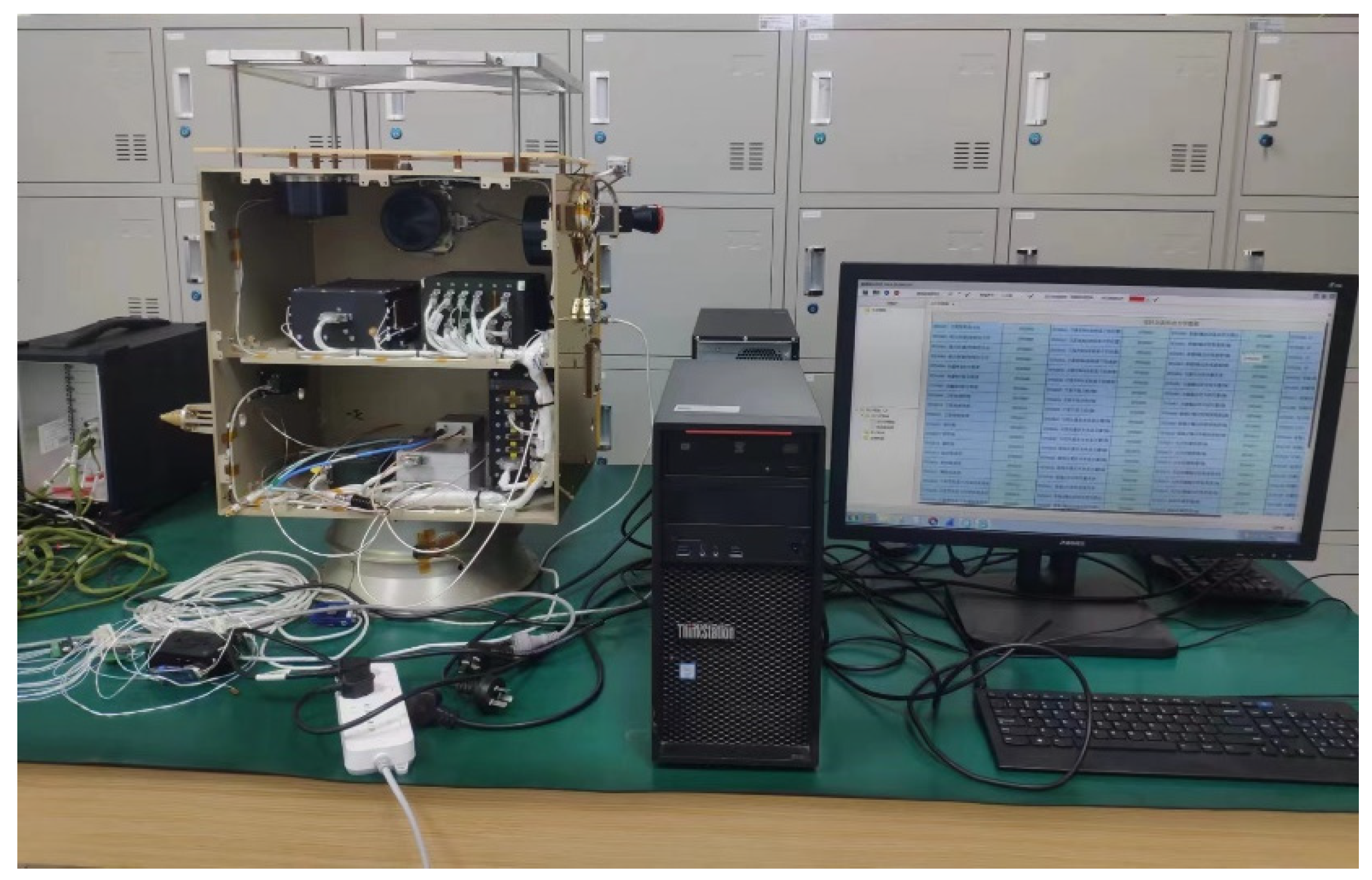
The following simulations involve moving target tracking using a semi-physical ground real-time simulation system for microsatellites. The system comprises an electric satellite, a real-time simulation machine, and ground measurement software (version V1.0), as depicted in
Figure 4. The electric satellite is composed and configured to mimic the real conditions of satellites in orbit, enabling the physical simulation of microsatellites. The real-time simulation machine facilitates the simulation of satellite orbital operations, environmental conditions, and target scenarios. The ground measurement software monitors and controls the satellite’s state.
The simulation conditions were set as follows: The satellite operates in a circular orbit at an altitude of 500 km from the Earth’s surface, with an inclination angle i = 30°, right ascension of the ascending node , and the initial ground projection geographical coordinates of the target point are (9.9727° N, 150.5970° E), with an altitude of 12 km, flying north at a speed of 0.8 Ma.
The moment of inertia for the microsatellite’s rotation was given by the following:
External environmental disturbance torque was configured as follows:
The controller parameters were set as
,
,
, and
. The disturbance observer parameters were set as
and
.
Table 1 reports the performance parameters of the flywheel.
Utilizing the method presented in
Section 3 provides the quaternion error and desired angular velocity between the current attitude and the desired attitude. The designed controller was then used to track the desired attitude. In this simulation, first the effectiveness of the disturbance observer was examined, with the corresponding results illustrated in
Figure 5 and
Figure 6.
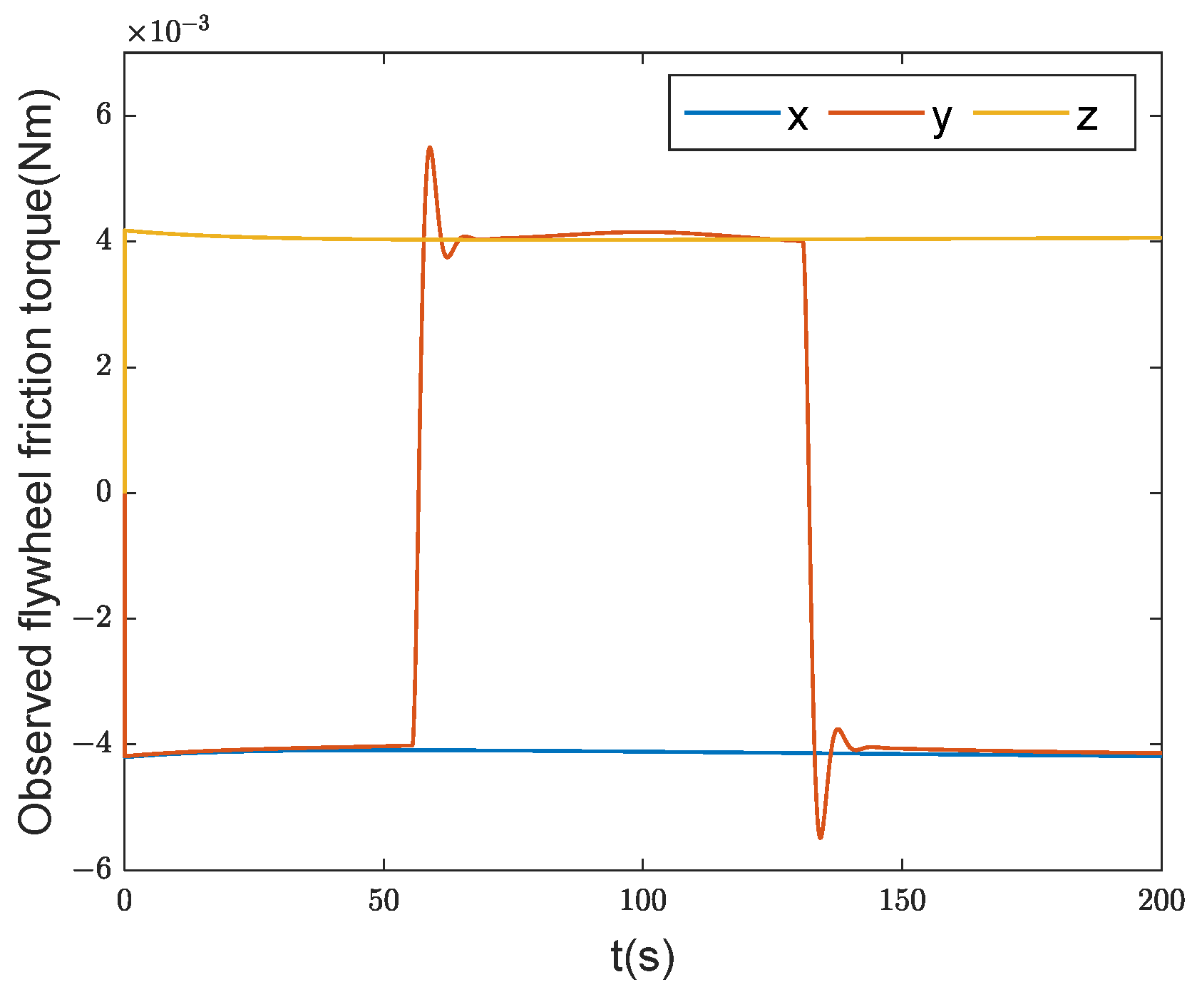
Figure 5 presents the actual friction torque values generated by the flywheel, and
Figure 6 displays the observed flywheel friction torque values obtained by the disturbance observer.
Figure 5 highlights that the flywheel experienced zero speed at 56 s and 132 s, resulting in a sudden change in frictional force. Comparing the two figures, it is evident that the designed disturbance observer successfully observed the frictional disturbance torque of the flywheel, albeit with a slight deviation at the zero-speed crossings.
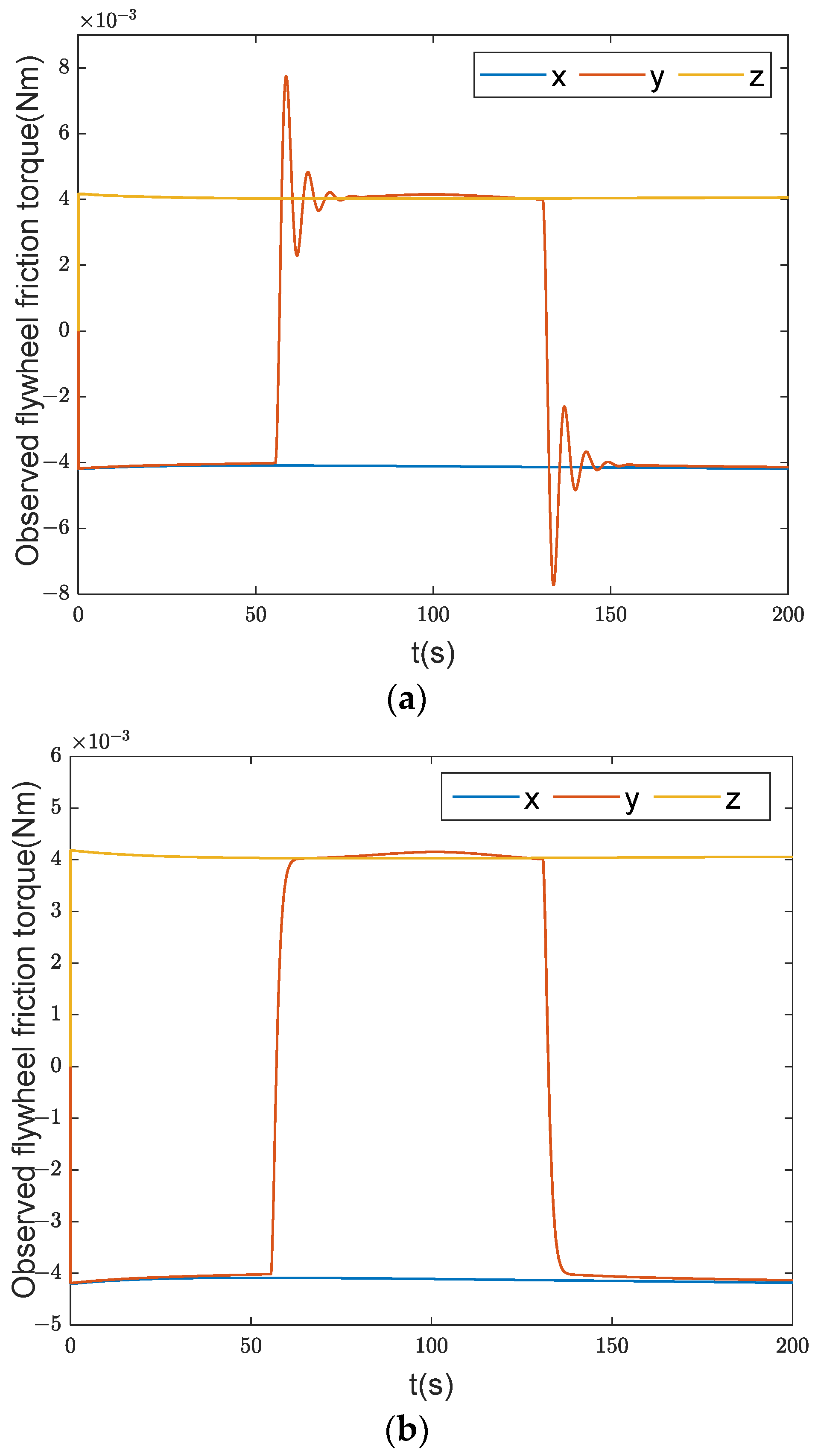
Four additional parameter combinations were simulated to demonstrate the impact of parameters
and
on the disturbance observer.
Table 2 reports the four datasets, and the corresponding simulation results are depicted in
Figure 7.
Figure 7a,b reveal that as the parameter
increased, the observer became less sensitive to abrupt changes in frictional force. Similarly,
Figure 7c,d highlight that as the parameter
decreased, the observer became less sensitive to abrupt changes in frictional force. In practical applications, a reasonable choice of observer parameters is crucial. Indeed, if
is too large, the observer becomes overly sensitive to sudden changes in frictional force, leading to oscillations in observed values at the point of frictional force transition, thereby affecting subsequent observations. Conversely, if
is too small, the observer may fail to detect abrupt changes in frictional force.
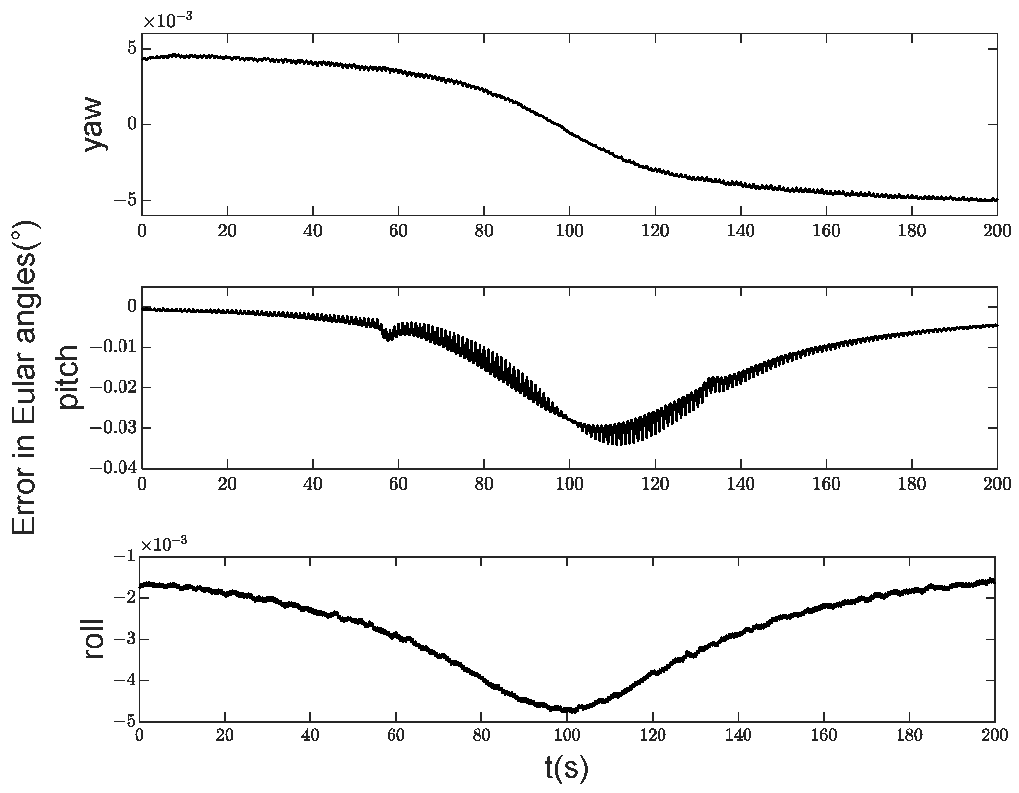
Next, the tracking performance of the controller was examined. For clarity, the quaternion attitude was converted to Euler angles. To verify the effectiveness of the designed controller, a comparative simulation was conducted between the controller without a disturbance observer and the controller with a feedforward compensation disturbance observer. The simulation results are illustrated in
Figure 8,
Figure 9,
Figure 10,
Figure 11,
Figure 12 and
Figure 13.
Figure 8 and
Figure 9 infer that the satellite achieved high accuracy in yaw and roll angles, while the pitch angle accuracy was slightly lower. Specifically, by the controller with the feedforward compensation disturbance observer, the yaw accuracy was 0.005°, the roll accuracy was 0.005°, and the pitch accuracy was 0.03°. According to the controller without disturbance observer, the yaw accuracy was 0.007°, the roll accuracy was 0.007°, and the pitch accuracy was 0.07°. Comparing the results of the two types of controllers, it can be seen that the controller designed in this article has approximately doubled in accuracy.
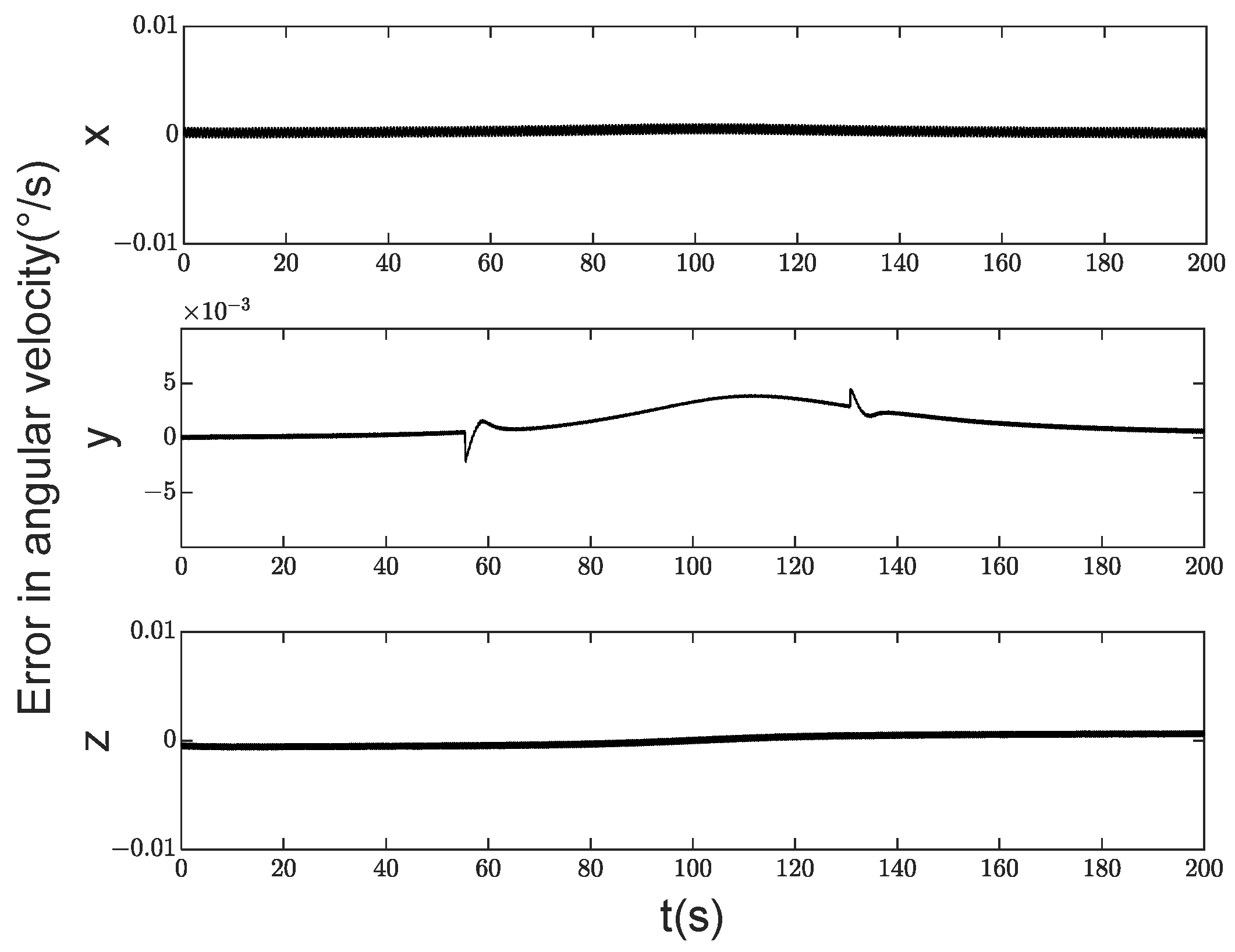
Figure 10 demonstrates that the satellite’s angular velocity control accuracy was high, with errors in all three axes maintained within 0.005°/s. From
Figure 11, it can be seen that the controller without disturbance observer significantly increased the error in the pitch axis direction, which was 0.01°/s. The lowest accuracy in satellite attitude was observed around 110 s, primarily because the satellite is closest to the target point at this time, resulting in rapid changes in satellite attitude. The deviation between attitudes at the previous and subsequent instants is significant within one control cycle, preventing complete convergence to zero. This gives rise to a certain level of attitude control error.
Figure 12 and
Figure 13 illustrate the variation of satellite control torques throughout the entire process. The
x-axis and
z-axis torques were almost zero, while the
y-axis direction had significant torque between 60 s and 140 s. The satellite’s attitude changed relatively quickly during this interval, calling for a large control torque. A sudden torque transition occurred around the 60 s and 130 s, and the controller without disturbance observer did not converge after the torque mutation. This is attributed to the zero crossing of the flywheel’s speed, where the flywheel friction torque transitions from moving friction to static friction and then back to moving friction, as indicated in the performance analysis of the disturbance observer.


