
Tests of Fire Circuit Breakers (FCBs) to Assess Their Suitability for Use in Construction Objects

Scientific and Research Centre for Fire Protection, National Research Institute, CNBOP-PIB, Nadwiślańska 213, 05-420 Józefów, Poland
*
Author to whom correspondence should be addressed.
Electronics 2024, 13(9), 1633; https://doi.org/10.3390/electronics13091633
Submission received: 21 March 2024
/
Revised: 20 April 2024
/
Accepted: 22 April 2024
/
Published: 24 April 2024
(This article belongs to the Special Issue Analog and Mixed Circuit: Design and Applications)
Abstract
:A fire circuit breaker (FCB) is dedicated to emergency services that can cut off the flow of electricity to all circuits, except for circuits supplying installations and equipment, the functioning of which is necessary during a fire. Theoretical research shows that there are no comprehensive studies on the FCB systems. Therefore, the aim of this study is to assess the impact of the components used (activating, signalling and executive devices) on the functionality of the entire FCB system (signal transmission time, actuation time, signalling, operational safety and resistance to various environmental conditions). This study proposes a new test scheme to evaluate the functionality of the entire FCB system, not just their individual components, which are widely known and used by electricians. However, it is only by combining them into a system, taking into account the requirements for firefighting equipment used by firefighters, that a completely new product is created. The new test scheme was properly validated by conducting a series of tests on several systems, consisting of multiple components (activating, signalling and executive devices). The tests carried out confirmed the validity of the assumptions made for the test methods and demonstrated the strong influence of the components (actuators, signalling and execution devices) on the functionality of the entire FCB system.
1. Introduction
A fire circuit breaker (FCB) is dedicated to emergency services that, upon arrival at the scene of a fire, can cut off the flow of electricity to all circuits, except for circuits supplying installations and equipment, the functioning of which is necessary during a fire and the conduct of rescue and firefighting operations. Installations and equipment powered by mains voltage include the following:
- fire pumps,
- fire alarm systems—optical and voice alarm devices,
- voice alarm systems,
- smoke and heat control systems—including powering ventilators and smoke damper drives),
- emergency and evacuation lighting,
- elevators intended for rescue teams.
There are no integrated guidelines in this area in the European Union. However, in Poland, FCB has been required since 1992. At that time, a requirement appeared in the Regulation of the Ministry of Internal Affairs [1] to use FCB in explosion-prone facilities and other facilities with a volume exceeding 1000 m3. Meanwhile, in 2010, FCB was classified as a fire protection device; consequently, there was an obligation for the FCB project to be agreed upon by a fire protection expert, and appropriate trials and tests should be carried out to confirm proper operation and the need for annual technical inspections and maintenance activities. An important change occurred in 2016, when FCBs were included in the list of construction products subject to a mandatory national declaration of performance [2]. In practice, this meant a certification and laboratory testing process for FCB sets or individual components of an FCB: an activating device, a signalling device or an executive device. The deadline for the obligation was postponed and finally set at 31 December 2021. Meanwhile, in 2021, the rules for drafting and agreeing on the design of a fire protection device (including FCB) were clarified [3]. This brief historical outline shows the evolution of the FCB approach to equipping construction objects.
In the United States of America, it is also necessary to use fire circuit breakers. According to NFPA 72 [4], the system circuit disconnecting means shall be marked to identify the system or equipment that it serves. For fire alarm and signalling systems, the circuit disconnecting means shall have a red marking, and the red marking shall not damage the overcurrent protective devices or obscure the manufacturer markings. Where a circuit breaker is the disconnecting means, an approved breaker locking device shall be installed. In addition, circuit disconnecting means shall be accessible only to authorised personnel.
The article summarises past experiences in the use of FCB and identifies areas for further discussion.
The purpose of the research conducted was to evaluate the impact of the components used (activating, signalling and executive devices) on the functionality of the entire FCB system (signal transmission time, actuation time, signalling, safety of use and resistance to various environmental conditions). The practical (utilitarian) goal was to propose a set of new test methods for evaluating the suitability of the entire FCB system for use in construction and to validate these methods and present test results for more than a dozen tested devices.
2. Legal Requirements—Analysis and Evaluation of the Current State
According to the international standard [5], a fire circuit breaker (also called a fire switch) is an electrical apparatus that shall be used to disconnect all circuits with the exception of circuits supplying the equipment whose operation during a fire is necessary. The switch could be a circuit breaker or a disconnector. In addition, conductors supplying fire protection equipment whose operation is necessary during a fire shall be connected at the power supply side of the fire switch and it shall be clearly identified. The above requirement is very general and freely implemented in different countries. More often than not, it is the electrical designer who decides how and what equipment is to be used to turn off the power in a building during a fire. However, this can cause problems in their proper use by firefighters during a fire. Therefore, in Poland, the requirements in this area are more formalised. As part of the ongoing work, a list of test methods has been developed to verify the correct operation of these devices.
The FCB consists of electrical devices that are generally available and only when connected together perform the function of disconnecting power and signalling this to firefighters. Consequently, when analysing the available scientific research in this area, it is not possible to find explicit publications that describe these devices in such detail. The most common tests carried out focus on ensuring that the electrical apparatus in question operates correctly and that its operation prevents the electrical system from causing a fire. General research on electrical circuit breakers and disconnectors has been carried out for many years. The study, conducted by Underwriters Laboratories, led to the introduction of arc-fault circuit interrupter technology combined with conventional circuit breakers. This present generation of AFCIs offers protection to mitigate the effects of arcing faults without presenting nuisance tripping problems [6] (pp. 145–162), [7] (p. 28).
The test results clearly show poor performance for some circuit breaker product lines. This increases the risk of fire and injury in the homes in which they are installed. The poor performance of some brands reflects deficiencies in the calibration, testing and quality control practices of those particular manufacturers, along with a serious failure of the testing [8] (pp. 75–86). The study [9] proposes a method for testing circuit breakers and disconnectors, excavated from the fire scene, and assessing their switch-on and switch-off status after a fire.
Paper [10] described a simplified design for the power supply of a production hall with a fire circuit breaker. In the proposed solution, the FCBs are formed by two independent systems consisting of actuators, remote actuation buttons and optical signalling of the continuity of the trip control circuit and the position status of the contacts of the actuators of each FCB. The proposed solution represents a compromise between the financial outlay and the required reliability for this type of system.
The publication [11] (pp. 42–47) describes the FCB design for photovoltaic installations. A fire safety switch based on carrier communication is designed to address the fire safety issues of photovoltaic modules. The specific design of the breaker and the controller are carried out. The circuit breaker collects the voltage and current data of each PV module, transmits them to the controller via power line carrier communication and then uploads them to the PV system monitoring platform via RS-485 to display the operation status of the PV module in real time. In addition, the PV module can be turned off through the PV system monitoring platform or by manually pressing the shutdown button on the controller, which can greatly reduce the high voltage on the DC side of the PV in case of fire to ensure personal safety.
- in buildings where there is a fire zone of more than 1000 m3 or a potentially explosive atmosphere,
- at the metro station control room,
- in tunnels (separately in each nave),
- in garrison school shooting ranges and special ranges.
FCB should be located near the main entrance to the facility or connector and appropriately marked [16].
While the requirement for FCB in certain facilities does not raise too many questions, it is troublesome to define what equipment is included in FCB and what is not. The device “fire circuit breaker” is variously defined by those involved in the design, installation and project agreement process. From the point of view of fire protection, the most important element of FCB is the activating button, which is intended to be operated by the firefighter-commander, and the location of the FCB activating button and the signalling of tripping of the actuating element are very important. What is important is its functionality and reliability, i.e., how to start the FCB, whether it is known which button to press and whether there is fault signalling. However, for the designer of electrical installations in a facility, the most important element is the actuator (an electrical apparatus such as a circuit breaker or disconnector, its electrical parameters), which performs the disconnection from the power source of selected elements of the electrical installation that do not need to operate during a fire. This creates a kind of misunderstanding among firefighters and electricians.
At present, on the basis of the Regulation of the Ministry of the Interior and Administration [2], the components of an FCB are as follows:
- an activating device,
- a signalling device,
- an executive device.
The definition of the components of FCB in the above regulation tidies up the subject and takes into account both issues important for fire protection and issues relevant to electricians.
This is the most elaborate case, as shown in Figure 1, where the FCB includes all components, the actuator is activated remotely by the activating device and the actuator tripping is signalled by a signalling device, among others.
According to the SEP standard [17], FCB control can be local or remote; so, in simple, uncomplicated installations, it is only possible to use an actuator with manual control, as shown in Figure 2.
Figure 1 and Figure 2 show two extreme cases of FCB application, from the most elaborate, in which all FCB elements are used (Figure 1), to a simplified version in which only the FCB actuator element is present (Figure 2). This approach means that a different type of test has to be performed to assess the suitability of a component for use as an FCB. Table 1 shows the proposed reference documents for the FCB element.
For the simplest solutions of the FCB executive device in the form of a locally/manually controlled circuit breaker or disconnector, the available standards IEC 60947-2 [18] or IEC 60947-3 [19] can be used. There are no developed standards for other FCB components and for remotely controlled FCB executive devices. Therefore, the evaluation of the performance of these products is carried out on the basis of National Technical Assessments [20]. The development of a National Technical Assessment [21] is preceded by tests in a testing laboratory.
3. Materials and Methods
3.1. Research Methods for Assessing the Suitability of FCBs
As part of the ongoing work, research methods have been developed to assess the suitability of FCBs in fire protection. The testing conducted for FCBs can be divided into 3 main groups:
- functional tests,
- environmental tests,
- EMC electromagnetic compatibility tests.
Functional tests are used to verify the functions that a device performs. These functions for fire protection equipment should be primarily useful from the point of view of fire protection. For FCB (as a whole), the most important function is to disconnect circuits in the electrical system that do not need to work during a fire.
Environmental tests, on the other hand, should verify the resistance and durability of the product to changes in the environmental conditions in its working surroundings, that is, changes in temperature, humidity or the presence of shock and vibration.
The last group of tests is electromagnetic compatibility testing. The tests are used to verify the product’s resistance to changes in supply voltage and interference of the electromagnetic origin.
These tests verify the ability of the device to operate both under normal conditions of use of the building, as well as in an emergency situation, such as a fire.
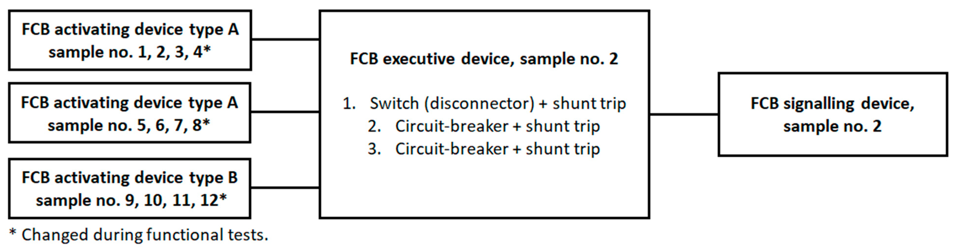
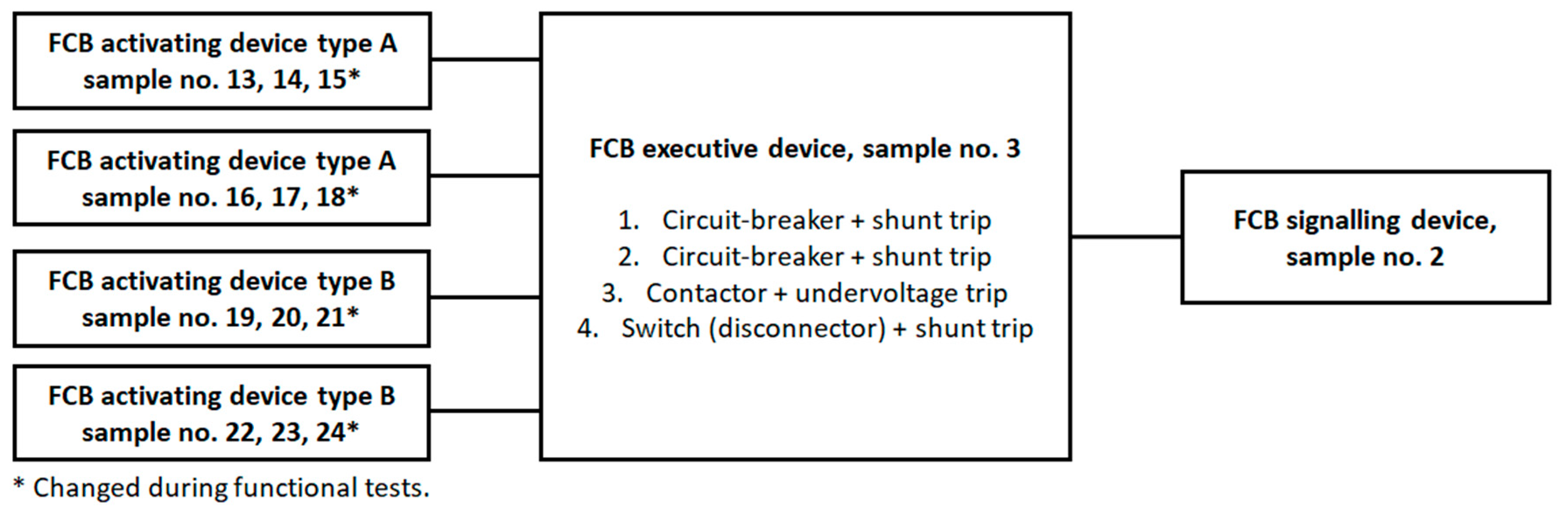
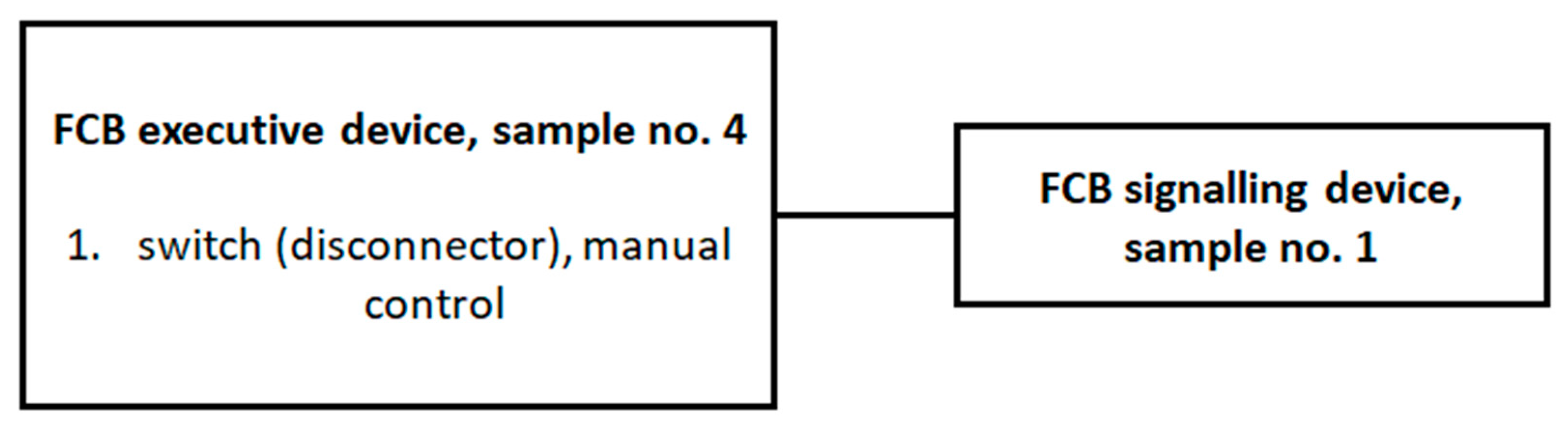
The test samples were selected to provide a wide range of activating, signalling and executive devices. The configuration was changed during the tests, as shown in the Figure 3, Figure 4, Figure 5, Figure 6, Figure 7 and Figure 8.
A series of functional, climatic and EMC tests were performed for the above-mentioned sets.
3.1.1. Functional Tests—Materials and Methods
Functional tests of the FCB activating device
The main, primary task of the FCB activating device is to transmit a signal to the FCB executive device about the need to disconnect electrical circuits to devices that do not need to operate during a fire. During normal operation, a red LED should be lit on the button to indicate that the FCB is ready and operating correctly.
However, the activation condition of the FCB activating device should occur as follows:
- when the fragile element is broken for type A switches,
- after the fragile element is broken and the switch is pressed for type B switches.
The time from the use of a switch to the activation of the executive device element and the activation of the signalling of the activation status should not exceed 60 s. Signalling of the activation status should be provided by a separate green light indicator. In the event of damage to the activating device or damage to the connection to the executive device, fault signalling should be provided (applied) on the executive device in the form of either extinguishing all light indicators (that is, red and green LEDs) or as a separate yellow light indicator. In practice, an easier solution to implement is to turn off the light indicators, instead of adding additional yellow signalling, for which a power supply must be provided, which can be problematic in case of damage. Signalling using light indicators should be visible at ambient light levels of up to 500 lux, at an angle of up to 22.5° measured relative to a line passing through the indicator and perpendicular to its mounting surface at a distance of 1 m.
The FCB activating device should also have a unified appearance regardless of the manufacturer; so that in each facility, it is easily distinguishable from the rest of the other devices. Hence, it was assumed that the faceplate of the manual switch should have a shape similar to a square. Corners and edges may be rounded, but the radius of rounding must not be greater than 5 mm. The operating field should be at the level of the faceplate or set back from it and should not extend beyond the faceplate. The dimensions of the faceplate and operating field should be within the dimensions specified in Figure 9 and Table 5. The faceplate of a manual switch, installed in accordance with the manufacturer’s instructions, should extend above the mounting plane at least 15 mm. The above requirements have been adapted from the EN 54-11 [22] standard for manual call points used in fire alarm systems.
In addition, the top of the device should bear the inscription “FIRE CIRCUIT BREAKER PUSHBUTTON”.
The FCB activating device should also have appropriate colours:
- housing and faceplate colour is red according to RAL 3000;
- the visible area of the control panel is white colour according to RAL 9010;
- the description colour is black according to RAL 9005;
- the operating button colour is yellow according to RAL 1018.
It can be concluded from the above that the distinguishing mark of the FCB switch from other switches (e.g., manual call point, manual smoke ventilation switch, technical switch) is a yellow-coloured operating switch, which is in accordance with the requirements of SEP-E-005:2013 [17].
An important functionality of the FCB activating device is also the possibility of resetting the activation condition of the FCB system. This functionality should not be implemented automatically. Power should be restored to the condition prior to activating the switch and power should be switched on at the FCB executive device. Resetting the activation condition only in the switch should not restore power to the deactivated circuits.
Functional tests of the FCB signalling device
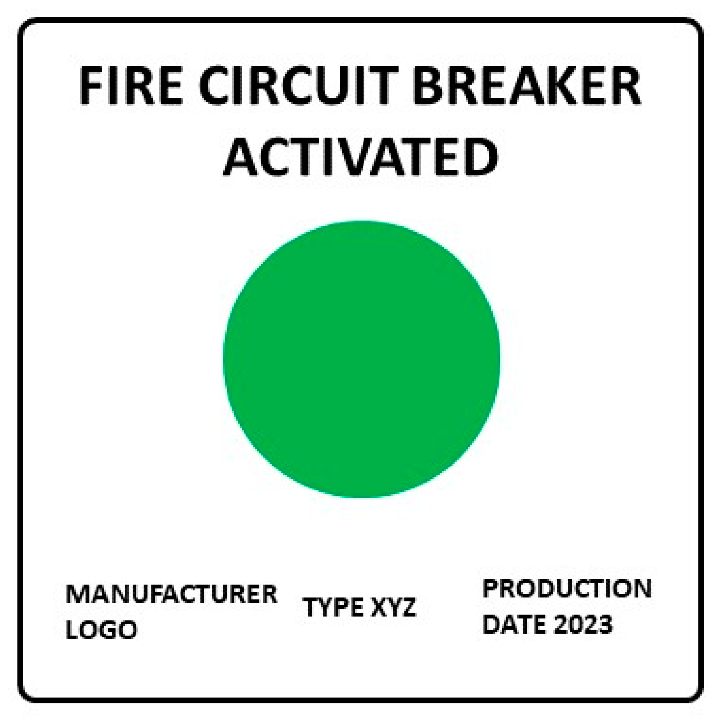
The task of the FCB signalling device is to signal at least optically the activation of the FCB executive device. The signalling should be continuous green. The signalling should be visible at ambient light levels of up to 500 lux from a distance of 6 m directly in front of the device. An example of the appearance of a signalling device is shown in Figure 10.
It can be deduced from the above requirements for the signalling device that the minimum dimensions and colours of the housing are not specified.
Functional tests of the FCB executive device
The main, basic task of the FCB executive device is first and foremost to disconnect all circuits, with the exception of circuits supplying systems and equipment whose functioning is essential during a fire and the rescue and fire-fighting operation. The executive device should disconnect the power supply before entering the building or fire zone concerned. Activation of the executive device should take place within 10 s, unless additional activations are provided, for example, lifts and UPS. Adequate information on the execution time of the activation delay should then be provided. The control of the executive device should be automatic (remote from the activating device) and manual (in the executive device itself). The key component of the FCB executive device is the circuit breaker or disconnector. In addition, it may include a rise-trigger, a fade-trigger (undervoltage), an automatic phase switch, relays, voltage presence detectors, overcurrent protection, surge arresters, a power supply/voltage converter, input/output modules (e.g., for transmitting information on the status of the device to the fire alarm system (FDAS) or the system integrating fire protection equipment (e.g., BMS)), buttons and indicators.
In the executive device, appropriate signalling should be provided. The operation quiescent condition should be indicated by a separate red indicator. On the other hand, signalling of the activation condition should be provided by a separate green light indicator. In the event of a fault condition, this should be signalled either by switching off the power supply to all light indicators (i.e., red and green LEDs) or as a separate yellow light indicator. Signals using light indicators should be visible at an ambient light intensity of up to 500 lux, at an angle of up to 22.5° measured in relation to a line passing through the indicator and perpendicular to its mounting surface at a distance of 3 m. The enclosure of the executive device shall bear the sign “Fire circuit breaker” according to PN-N-01256-04:1997 [16].
In addition, if the executive device also controls the continuity of the line to the activating and signalling devices, the executive device should be equipped with a power supply providing backup power for a minimum of 30 min.
The restoration of power and the resetting of the signal, which caused the executive device to be triggered and the electricity to be disconnected, should only be carried out manually by conscious action on the part of authorised persons.
During functional tests of the executive device, it should be checked that the disconnector/breaker switches off the circuits. During the test, there should be no permanent arcing or jumping between poles or between poles and base. The connector should remain mechanically functional. A contact fusion that makes it impossible to open the switch by normal means is not permitted. Slight wear on the mechanism and contacts is acceptable, provided that the switch operates correctly. In the case of triggers, the operating ranges must be examined and whether the trigger causes the breaker to open within the specified voltage limits.
3.1.2. Environmental Tests—Materials and Methods
The purpose of carrying out environmental tests is to demonstrate the ability of FCB components to operate correctly in the specified environment, at low and high ambient temperatures, under high relative humidity conditions, resistance to mechanical stress, shock and vibration, as well as the ability to withstand transport, storage and installation conditions.
Fire-fighting equipment is usually tested based on the requirements of the EN IEC 60068 [23] series of standards. Therefore, by analogy, tests using the above series of standards have been proposed for FCB elements. As FCB components can be deployed in different parts of buildings and even outdoors, a classification into climate classes has been proposed, which determines the operating temperature range and the required IP degree of protection of the enclosure (Table 6).
The proposed tests and exposure values are in line with the requirements for other fire protection equipment, e.g., control panels for fire protection equipment or power supplies used to power fire protection equipment. Exposures correspond to conditions that may occur during normal operation as well as in an emergency work situation. Prior to exposure, the device under test should be subjected to a functional check. During exposure, the device should be monitored to detect any changes in the operating condition. After final stabilisation, the functional test should be performed again and the device should be visually inspected for the presence of both external and internal mechanical damage. A sample is considered to have passed the test if the working condition is maintained and the functional test is passed.
3.1.3. Electromagnetic Compatibility Tests—Materials and Methods
The last group of tests is electromagnetic compatibility testing. The tests serve to verify the product’s resistance to variations in supply voltage and interference of electromagnetic origin. The resulting electromagnetic interference can reach the FCB both by wire and wirelessly. These interferences can cause either accidental activations or sometimes permanent damage.
The following tests, based on the requirements of EN 50130-4 [32], are to be carried out as part of the research:
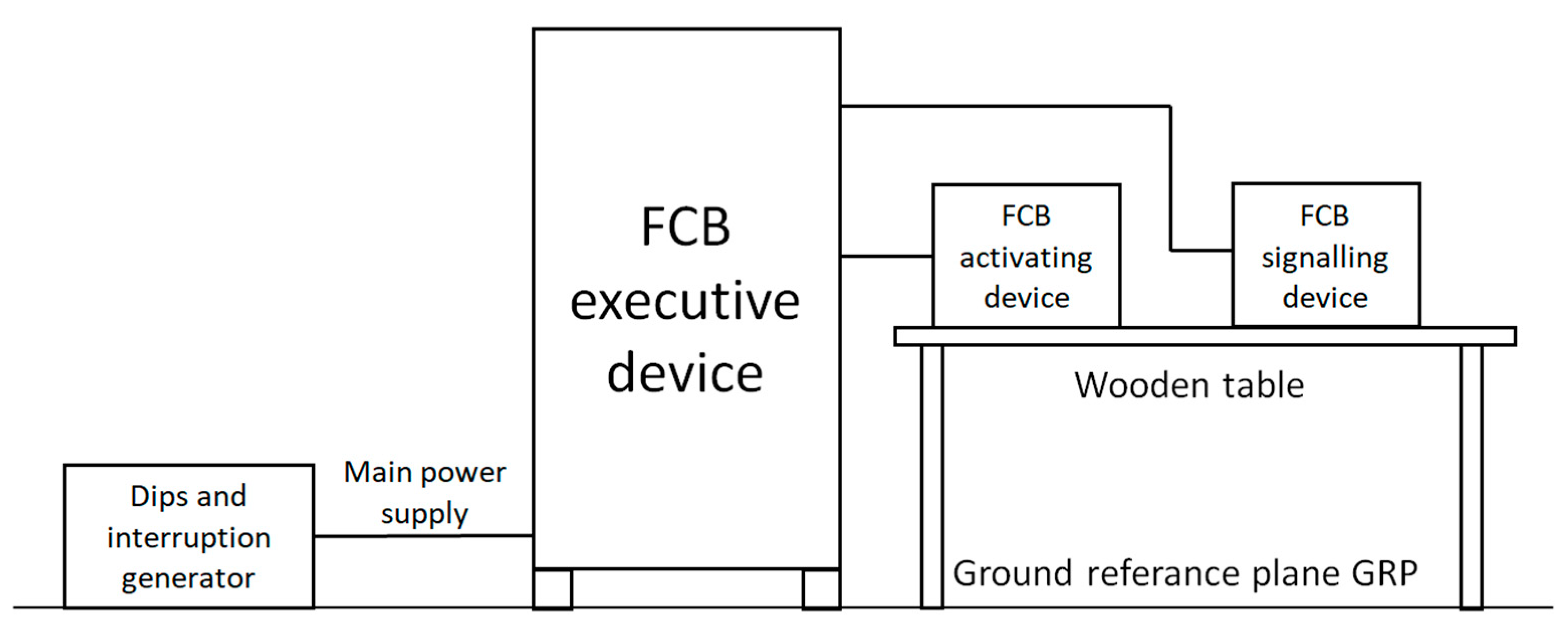
- Changes in the mains voltage (only for the executive device): This is intended to demonstrate the ability of the device to operate correctly despite changes in the mains conditions in the range of Unom +10–15% (Unom—nominal voltage), test method and test equipment according to IEC 61000-4-11:2004/AMD1:2017 [33], test setup as shown in Figure 11 (EM test manufacturer)
- Mains voltage decays and short interruptions (only for the executive device): This is intended to demonstrate the resistance of the device to short AC mains voltage decays (drops) and interruptions, such as those caused by load switching and the operation of protective devices in distribution networks; the test includes applying short-circuit decays and interruptions of the mains voltage to the device (3 voltage drops of 20%, 30%, 60% and 100% each), test method and test equipment according to IEC 61000-4-11:2004/AMD1:2017, test setup as shown in Figure 11 (EM test manufacturer)
- Electrostatic discharge: This is intended to demonstrate the immunity of the equipment to electrostatic discharges caused by operators of the equipment, who may be electrostatically charged, touching this equipment or other equipment in the vicinity; the test includes applying electrostatic discharges to parts of the equipment accessible to the operator and to coupled planes located at a distance of 0.1 m from the equipment (10 discharges each of 2, 4 and 8 kV for air discharges and 6 kV for contact discharge), test method and test equipment according to IEC 61000-4-2:2008 [34], test setup as shown in Figure 12 (EM test manufacturer)
- Radiated electromagnetic field: This is intended to demonstrate the immunity of a device to electromagnetic fields generated, for example, by portable radio transceivers or mobile phones; the test consists of exposing the device to an electromagnetic field with a field strength of 10 V/m, frequency sweeping from 80 MHz to 2.7 GHz, with the signal modulated both in amplitude (first test) and pulse (second test), test method and test equipment according to IEC 61000-4-3:2020 [35], test setup as shown in Figure 13 (EMCO and Schwarzbeck—Mess-Elektronik manufacturers)
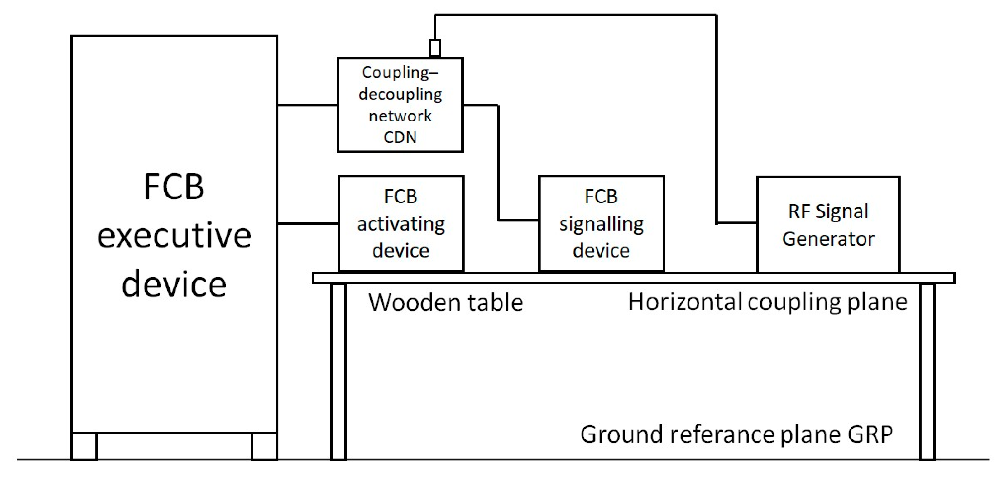
- Conducted disturbances induced by electromagnetic fields: This is intended to demonstrate the immunity of a device to conducted disturbances induced by electromagnetic fields in the wiring field (e.g., generated by portable radio transceivers, radiotelephones); the test includes introducing a radio frequency disturbance with a voltage level of 10 V, in the range of 150 kHz to 100 MHz, to various inputs or outputs of the device under test, with a signal modulated both in amplitude (first test) and in pulse (second test), test method and test equipment according to IEC 61000-4-6:2013 [36], test setup as shown in Figure 14 (EM test manufacturer)
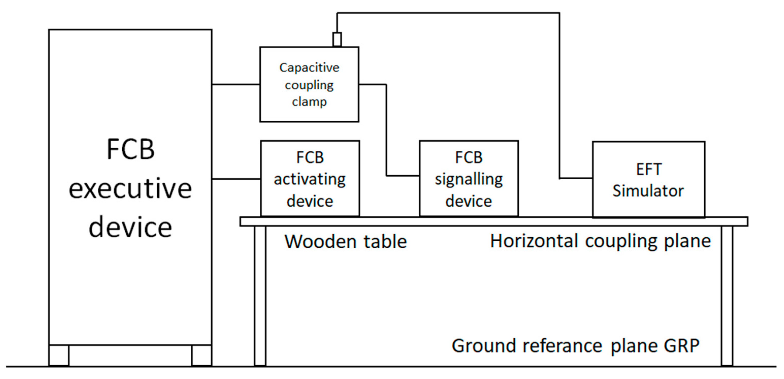
- Series of fast electrical transients: This is intended to demonstrate the immunity of the device to a series of fast transients of low energy, which can be caused by relays, contacts, as well as switching loads of an inductive nature that can be induced in the signal circuits; the test consists in introducing a series of fast transients to the power supply lines and signal inputs/outputs of the device with a voltage value of 2 kV for the AC power supply lines and 1 kV for the other lines at a repetition rate of 100 kHz, for 1 min, test method and test equipment according to IEC 61000-4-4:2012 [37], test setup as shown in Figure 15 (EM test manufacturer)
- Slow high-energy voltage surges: This is intended to demonstrate the immunity of the equipment to relatively slow, transient high-energy pulses that may be induced in power and signal cables from close lightning discharges or from switching in the power system or in the low-voltage network; the test involves the introduction of slow, transient high-energy pulses in both line-to-line and line-to-ground coupling systems at 0.5 and 1 kV (line-to-line) and 0.5; 1 and 2 kV (line-to-ground) for AC power lines and 0.5 and 1 kV (line-to-ground) for other lines, test method and test equipment according to IEC 61000-4-5:2014/AMD1:2017 [38], test setup as shown in Figure 16 (EM test manufacturer)
Prior to exposure, the device under test should be subjected to a functional test according to Section 3.1.1. During exposure, the device should be monitored to detect any changes in operating conditions. After final stabilisation, the functional test should be performed again and the device should be visually inspected for the presence of both external and internal mechanical damage. A sample is considered to have passed the test if the working condition is maintained and the functional test is passed.
4. Results
Tests were carried out for 36 activating devices, 4 signalling devices and 6 executive devices. The test samples were prepared as prototype samples by four manufacturers. The product samples were stored in a separate warehouse, at room temperature and normal humidity.
A whole series of functional, environmental and electromagnetic compatibility tests were performed. Of the devices tested, the following results were obtained:
- the FCB activating devices: 36 pieces received positive results in environmental class 2 (23 pieces of type A and 13 pieces of type B),
- the FCB signalling devices: 1 piece received positive results in environmental class 1 and 3 pieces in environmental class 2.
- the FCB executive devices: 4 pieces received positive results in environmental class 1 and 2 pieces in environmental class 2.
Not all samples of FCB signalling and FCB executive devices achieved an environmental class 2 (Figure 17). In this case, the decisive tests were the higher IP degree of protection for the enclosure (IP54 instead of IP30) and the SO2 corrosion resistance test (test conducted only for class 2).
Detailed test results for FCB signalling and FCB executive devices are presented in Table 7 and Table 8.
However, in the case of FCB activating devices, all the tested samples have achieved environmental class 2, i.e., they can be installed both inside and outside buildings (except for one sample that obtained environmental class 1, i.e., it can only be used indoors—sample no. 36). For the FCB activating devices, for all 36 samples tested, the time from pressing the pushbutton to triggering the actuator and triggering the actuation status indication was a maximum of 3 s, and their dimensions were in accordance with the requirements in Table 2. Moreover, no mechanical damage was found for all samples after environmental and EMC testing (Figure 18). With the exception of one—sample no. 36, all samples achieved an IP54 enclosure rating (Figure 19).
During the EMC compatibility testing, tests were conducted for all device enclosures and for all input/output lines (i.e., 3x230V AC power line, FCB device interconnection, relay outputs to other systems such as BMS).
After the environmental and EMC electromagnetic compatibility tests, the most important moment was verifying the functionality of individual elements and their operation in the entire system. Functional tests were conducted for all measurement sets 1–6. The tests were aimed at verifying the correctness of the cooperation of the various components. The measurement sets worked properly and showed no damage during the tests as mentioned in Section 3.1.1.
5. Discussion and Conclusions
The term “fire circuit breaker” is defined in different ways. From a fire protection point of view, the most important element of FCB is the activation switch, which is operated by the firefighter, its location and the indication that the actuating element has been triggered. What is important is its functionality and reliability, i.e., how to start FCB, whether it is clear which switch to press and whether there is fault signalling. On the other hand, for the electrical designer, the most important element is the actuating element (an electrical apparatus such as a circuit breaker or disconnector, its electrical parameters), which performs the disconnection from the power source of selected elements of the electrical installation that do not need to operate during a fire.
The purpose of the tests conducted was to evaluate the impact of the components used (activating, signalling and executive devices) on the functionality of the entire FCB system (signal transmission time, actuation time, signalling, safety of use and resistance to various environmental conditions). The practical (utilitarian) goal was to propose a set of new test methods for evaluating the suitability of the entire FCB system for use in construction and to validate these methods.
Theoretical research shows that there are no comprehensive studies of the FCB system. While we can find information about ongoing research on individual components (e.g., disconnects, circuit breakers, triggers, or signals and keypads), there is no research that covers the entire FCB system. Individual components are widely known and used by electricians. However, it is only by combining them into a system, taking into account the requirements for firefighting equipment used by firefighters, that a completely new product is created. Only for the simplest FCB executive device solutions in the form of a locally/manually controlled circuit breaker or disconnector, the available IEC 60947-2 or IEC 60947-3 standards can be used. For the remaining FCB components and for remotely controlled FCB executive devices, testing should be carried out on the test procedures proposed in this publication.
In terms of the entire FCB system, there is no research. Accordingly, a new test scheme was proposed and properly validated by conducting a series of tests of several systems. The tested samples consisted of a total of more than 40 publication elements (activating, signalling and executive devices), and in the opinion of the authors, the conducted tests confirmed the validity of the assumptions made for the test methods and demonstrated the large impact of the components used (activating, signalling and executive devices) on the functionality of the entire FCB system. The empirical tests carried out confirmed the suitability of FCB elements for use in buildings. All the tested activating devices achieved environmental class 2, i.e., they can be installed both inside and outside buildings. However, not all samples of signalling and executive devices achieved an environmental class 2. In this case, the decisive tests were tests of the higher IP degree of protection of the enclosure and tests of resistance to operation in the SO2-corrosive atmosphere.
The developed set of new testing methods (primarily in the area of functional testing of the entire FCB system) can be used in further scientific research, but it also has a practical dimension—it can be used to assess the suitability of FCB systems for use in buildings. The proposed test scheme also provides material for further considerations and possible studies, such as the impact of the type of communication system (e.g., wired, wireless) and cabling (e.g., wires, fiber optics) on the functionality and correctness of FCB systems. In addition to the tests of FCB components, further work is needed on the design and installation of these devices in buildings.
Author Contributions
Conceptualisation, T.P. and P.S.; methodology, T.P. and M.C.; software, T.P. and P.S.; validation, T.P. and P.S.; formal analysis, T.P. and M.I.; investigation, T.P. and M.C.; resources, T.P. and M.I.; data curation, T.P.; writing—original draft preparation, T.P. and P.S.; writing—review and editing, T.P., M.C. and M.I.; visualisation, M.I.; supervision, T.P.; project administration, T.P.; funding acquisition, T.P. All authors have read and agreed to the published version of the manuscript.
Funding
Funding for publication of the article is provided from subvention of the Polish Ministry of Science and Higher Education, category: Other scientific activities.
Data Availability Statement
Data are contained within the article.
Conflicts of Interest
The authors declare no conflicts of interest.
References
- Regulation of the Minister of Internal Affairs of 3 November 1992 on Fire Protection of Buildings, Other Facilities and Areas (Polish Journal of Laws: Dz. U. Nr 92, poz. 460, as Amended), Outdated Document. Available online: https://isap.sejm.gov.pl/isap.nsf/DocDetails.xsp?id=WDU19920920460 (accessed on 20 April 2024).
- Regulation of the Minister of Infrastructure and Construction of 17 November 2016 on the Method of Declaring the Performance of Construction Products and the Method of Marking Them with the Construction Mark (Polish Journal of Laws: Dz. U. poz. 1966, as Amended). Available online: https://isap.sejm.gov.pl/isap.Nsf/DocDetails.xsp?id=WDU20160001966 (accessed on 20 April 2024).
- Regulation of the Minister of Internal Affairs and Administration of 17 September 2021 on Reconciliation of the Land or Plot Development Project, Architectural and Construction Project, Technical Project and the Project of Fire-Fighting Equipment in Terms of Compliance with the Fire Protection Requirements (Polish Journal of Laws: Dz. U. poz. 1722). Available online: https://isap.sejm.gov.pl/isap.nsf/DocDetails.xsp?id=WDU20210001722 (accessed on 20 April 2024).
- National Fire Protection Association. NFPA 72 National Fire Alarm and Signaling Code, 2022 ed.; National Fire Protection Association: Quincy, MA, USA, 2022. [Google Scholar]
- IEC 60364-5-56:2018; Low-Voltage Electrical Installations—Part 5–56: Selection and Erection of Electrical Equipment–Safety Services. International Electrotechnical Commission: Geneva, Switzerland, 2014.
- Lee, D.A.; Trotta, A.M.; King, W.H., Jr. New Technology for Preventing Residential Electrical Fires: Arc-Fault Circuit Interrupters (AFCIs). Fire Technol. 2000, 36, 145–162. [Google Scholar] [CrossRef]
- Franklin, F.F. Circuit Breakers: The Myth of Safety. Prof. Saf. Des. Plaines 1990, 6, 28. [Google Scholar]
- Aronstein, J. Faulty Residential Circuit Breakers–A Persistent Fire Safety Problem in IEEE. Open J. Ind. Appl. 2023, 4, 75–86. [Google Scholar] [CrossRef]
- Wang, L.; Li, D.; Guo, C. Technical Appraisal Method of Circuit Breaker Material Evidence in Fire Journal of Physics: Conference Series. In Proceedings of the 10th Annual International Conference on Material Science and Environmental Engineering, Nanjing, China, 25–27 November 2022. [Google Scholar]
- Wiatr, J.; Orzechowski, M. Uproszczony projekt zasilania hali produkcyjnej z przeciwpożarowym wyłącznikiem prądu zgodnie z wymaganiami normy PN-HD 60364-5-56:2019-01. Elektro Info 2021, 6, 7–8. [Google Scholar]
- He, J.; Bao, G. Design of Safety Fire Switch for Photovoltaic Module. Low Volt. Appar. 2023, 7, 42–47. [Google Scholar]
- Regulation of the Minister of Infrastructure of 12 April 2002 on the Technical Conditions to be Met by Buildings and Their Location (Polish Journal of Laws: Dz. U. z 2022 r. poz. 1225). Available online: https://isap.sejm.gov.pl/isap.nsf/DocDetails.xsp?id=WDU20220001225 (accessed on 20 April 2024).
- Regulation of the Minister of Defense of 4 October 2001 on the Technical Conditions to be Met by Garrison Shooting Ranges and Their Location (Polish Journal of Laws: Dz. U. Nr 132, poz. 1479, as Amended). Available online: https://isap.sejm.gov.pl/isap.nsf/DocDetails.xsp?id=WDU20011321479 (accessed on 20 April 2024).
- Regulation of the Minister for Infrastructure of 17 June 2011 on the Technical Conditions to be Met by Metro Structures and Their Location (Polish Journal of Laws: Dz. U. Nr 144, poz. 859). Available online: https://isap.sejm.gov.pl/isap.nsf/DocDetails.xsp?id=WDU20111440859 (accessed on 20 April 2024).
- Regulation of the Minister of Infrastructure of 24 June 2022 on Technical and Construction Regulations for Public Roads (Polish Journal of Laws: Dz. U. poz. 1518). Available online: https://isap.sejm.gov.pl/isap.nsf/DocDetails.xsp?id=WDU20220001518 (accessed on 20 April 2024).
- PN-N-01256-4:1997; Safety Signs–Technical Fire Protection Measures. The Polish Committee for Standardization PKN: Warsaw, Poland, 1997.
- SEP-E-005:2013; Selection of Electrical Conductors to Supply Power to Fire-Fighting Equipment Whose Operation Is Essential During a Fire. Association of Polish Electrical Engineers SEP: Warsaw, Poland, 2013.
- IEC 60947-2:2016; Low-Voltage Switchgear and Control Gear–Circuit-Breakers. International Electrotechnical Commission: Geneva, Switzerland, 2016.
- IEC 60947-3:2020; Low-Voltage Switchgear and Control Gear–Switches, Disconnectors, Switch-Disconnectors and Fuse-Combination Units. International Electrotechnical Commission: Geneva, Switzerland, 2020.
- Act of 16 April 2004 on Construction Products (Polish Journal of Laws: Dz. U. z 2021 r. poz. 1213). Available online: https://isap.sejm.gov.pl/isap.nsf/DocDetails.xsp?id=WDU20210001213 (accessed on 20 April 2024).
- Regulation of the Minister of Infrastructure and Construction of 17 November 2016 on National Technical Assessments (Polish Journal of Laws: Dz. U. poz. 1968). Available online: https://isap.sejm.gov.pl/isap.nsf/DocDetails.xsp?id=WDU20160001968 (accessed on 20 April 2024).
- EN 54-11:2001/A1:2005; Fire Detection and Fire Alarm Systems–Manual Call Points. European Standards. The European Committee for Standardization CEN: Brussels, Belgium, 2005.
- IEC 60068; Environmental Tests (Series of Standards). International Electrotechnical Commission: Geneva, Switzerland, 2024.
- IEC 60068-2-1:2007; Environmental Testing—Part 2–1: Tests–Test A: Cold. International Electrotechnical Commission: Geneva, Switzerland, 2007.
- IEC 60068-2-78:2012; Environmental Testing—Part 2–78: Tests–Test Cab: Damp Heat, Steady State. International Electrotechnical Commission: Geneva, Switzerland, 2012.
- IEC 60529:1989; Degrees of Protection Provided by Enclosures (IP Code). International Electrotechnical Commission: Geneva, Switzerland, 1989.
- IEC 60068-2-6:2007; Environmental Testing—Part 2–6: Tests–Test Fc: Vibration (Sinusoidal). International Electrotechnical Commission: Geneva, Switzerland, 2007.
- IEC 60068-2-75:2014; Environmental Testing—Part 2-75: Tests–Test Eh: Hammer Tests. International Electrotechnical Commission: Geneva, Switzerland, 2014.
- IEC 60068-2-27:2008; Environmental Testing—Part 2–27: Tests–Test Ea and Guidance: Shock. International Electrotechnical Commission: Geneva, Switzerland, 2014.
- ISO 22479:2019; Corrosion of Metals and Alloys. Sulfur Dioxide Test in a Humid Atmosphere (Fixed Gas Method). International Organization for Standardization: Geneva, Switzerland, 2019.
- IEC 60068-2-42:2003; Environmental Testing—Part 2–42: Tests–Test Kc: Sulphur Dioxide Test for Contacts and Connections. International Electrotechnical Commission: Geneva, Switzerland, 2003.
- EN 50130-4:2011+A1:2014; Alarm Systems–Electromagnetic Compatibility. Product Family Standard: Immunity Requirements for Components of Fire, Intruder, Hold Up, CCTV, Access Control and Social Alarm Systems. European Standards: Brussels, Belgium, 2014.
- IEC 61000-4-11:2004/AMD1:2017; Electromagnetic Compatibility (EMC)—Part 4–11: Testing and Measurement Techniques–Voltage Dips, Short Interruptions and Voltage Variations Immunity Tests for Equipment with Input Current up to 16 A per Phase. International Electrotechnical Commission: Geneva, Switzerland, 2017.
- IEC 61000-4-2:2008; Electromagnetic compatibility (EMC)—Part 4-2: Testing and Measurement Techniques-Electrostatic Discharge Immunity Test. International Electrotechnical Commission: Geneva, Switzerland, 2008.
- EC 61000-4-3:2020; Electromagnetic Compatibility (EMC)—Part 4–3: Testing and Measurement Techniques–Radiated, Radio-frequency, Electromagnetic Field Immunity Test. International Electrotechnical Commission: Geneva, Switzerland, 2020.
- IEC 61000-4-6:2013; Electromagnetic Compatibility (EMC)—Part 4–6: Testing and Measurement Techniques–Immunity to Conducted Disturbances, Induced by Radio-Frequency Fields. International Electrotechnical Commission: Geneva, Switzerland, 2013.
- IEC 61000-4-4:2012; Electromagnetic Compatibility (EMC)—Part 4–4: Testing and Measurement Techniques–Electrical Fast Transient/Burst Immunity Test. International Electrotechnical Commission: Geneva, Switzerland, 2012.
- IEC 61000-4-5:2014/AMD1:2017; Electromagnetic Compatibility (EMC)—Part 4–5: Testing and Measurement Techniques–Surge Immunity Test. International Electrotechnical Commission: Geneva, Switzerland, 2017.
Figure 1.
Proposed configuration of FCB block diagram—remote control.

Figure 2.
Proposed configuration of FCB block diagram—simplified version—local, manual control.
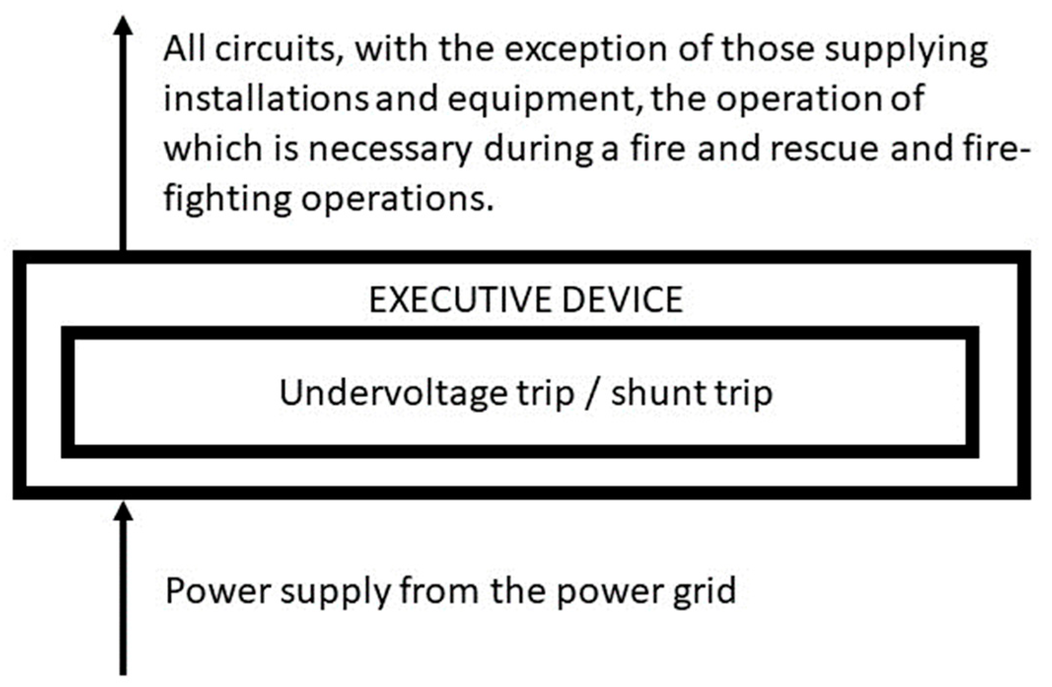
Figure 3.
Scheme of the experimental arrangement—test set no. 1.

Figure 4.
Scheme of the experimental arrangement—test set no. 2.

Figure 5.
Scheme of the experimental arrangement—test set no. 3.

Figure 6.
Scheme of the experimental arrangement—test set no. 4.

Figure 7.
Scheme of the experimental arrangement—test set no. 5.
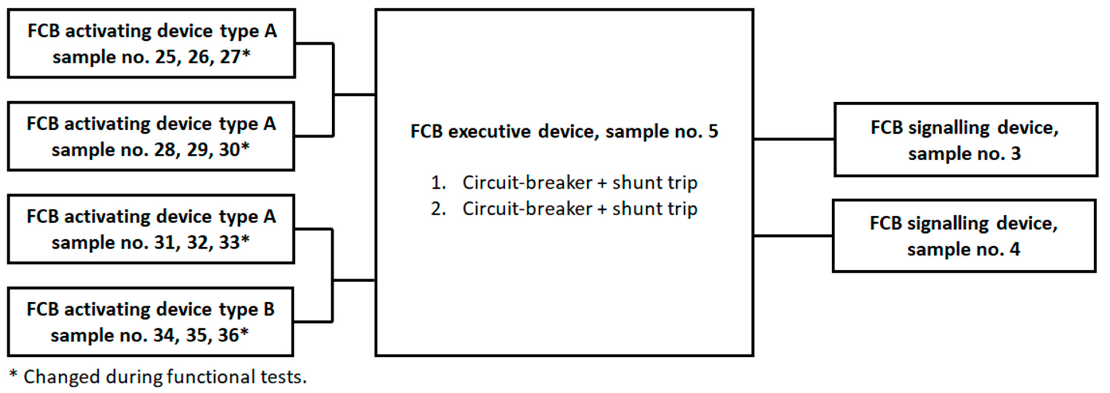
Figure 8.
Scheme of the experimental arrangement—test set no. 6.
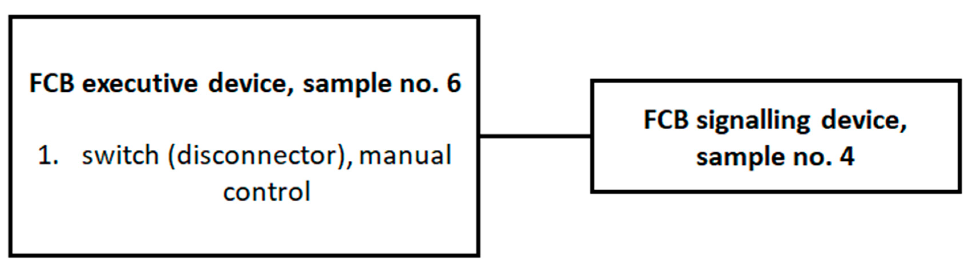
Figure 9.
A proposed view of the FCB activating device.
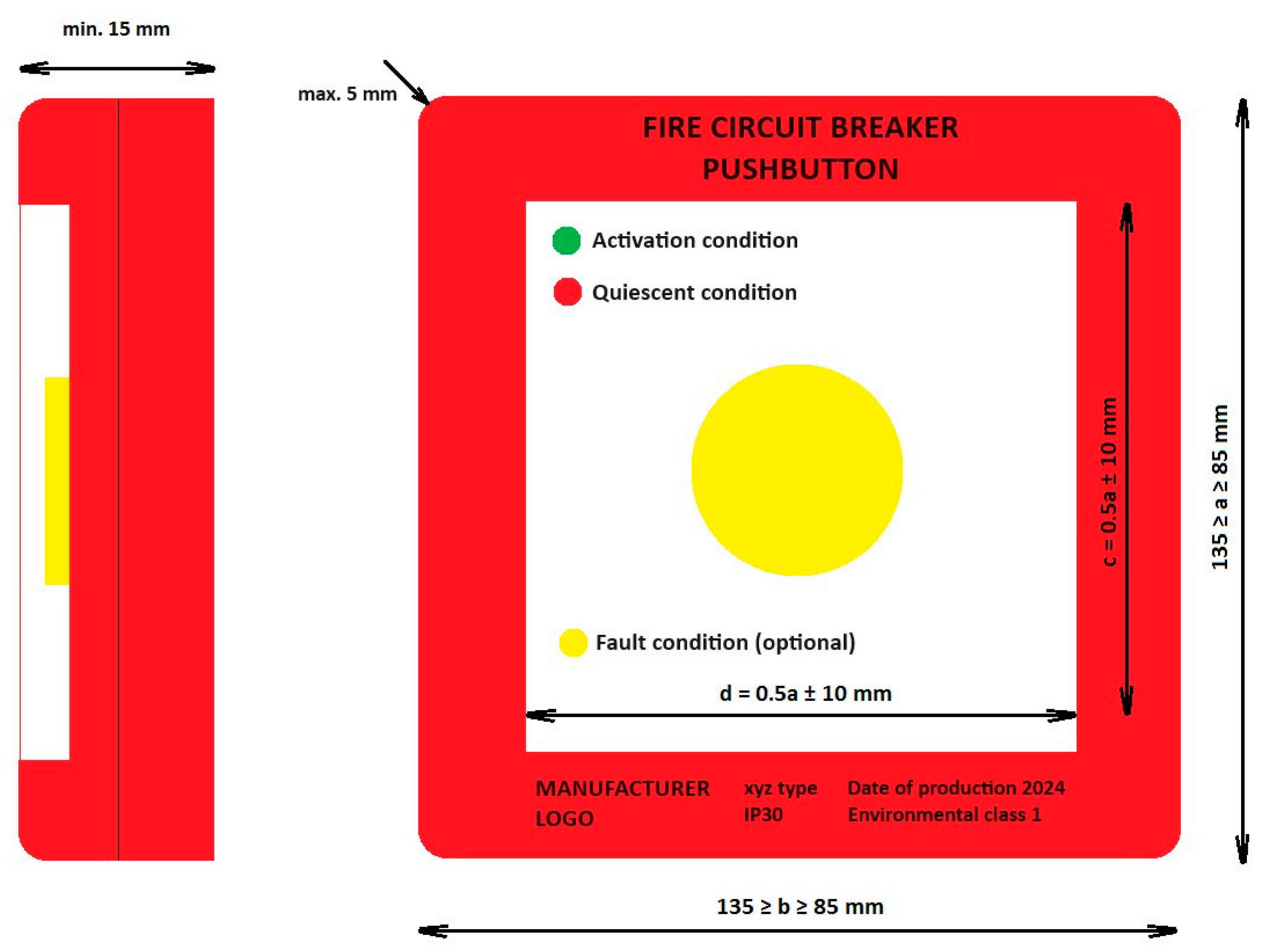
Figure 10.
A proposed view of the FCB signalling device.

Figure 11.
A simplified view of the mains voltage dips and interruption measurement configuration.

Figure 12.
A simplified view of the ESD measurement configuration.

Figure 13.
A simplified view of the radiated electromagnetic field measurement configuration.

Figure 14.
A simplified view of the conducted disturbances measurement configuration.

Figure 15.
A simplified view of the series of fast electrical transients measurement configuration.

Figure 16.
A simplified view of the series of slow high-energy voltage surges measurement configuration.
Figure 16.
A simplified view of the series of slow high-energy voltage surges measurement configuration.
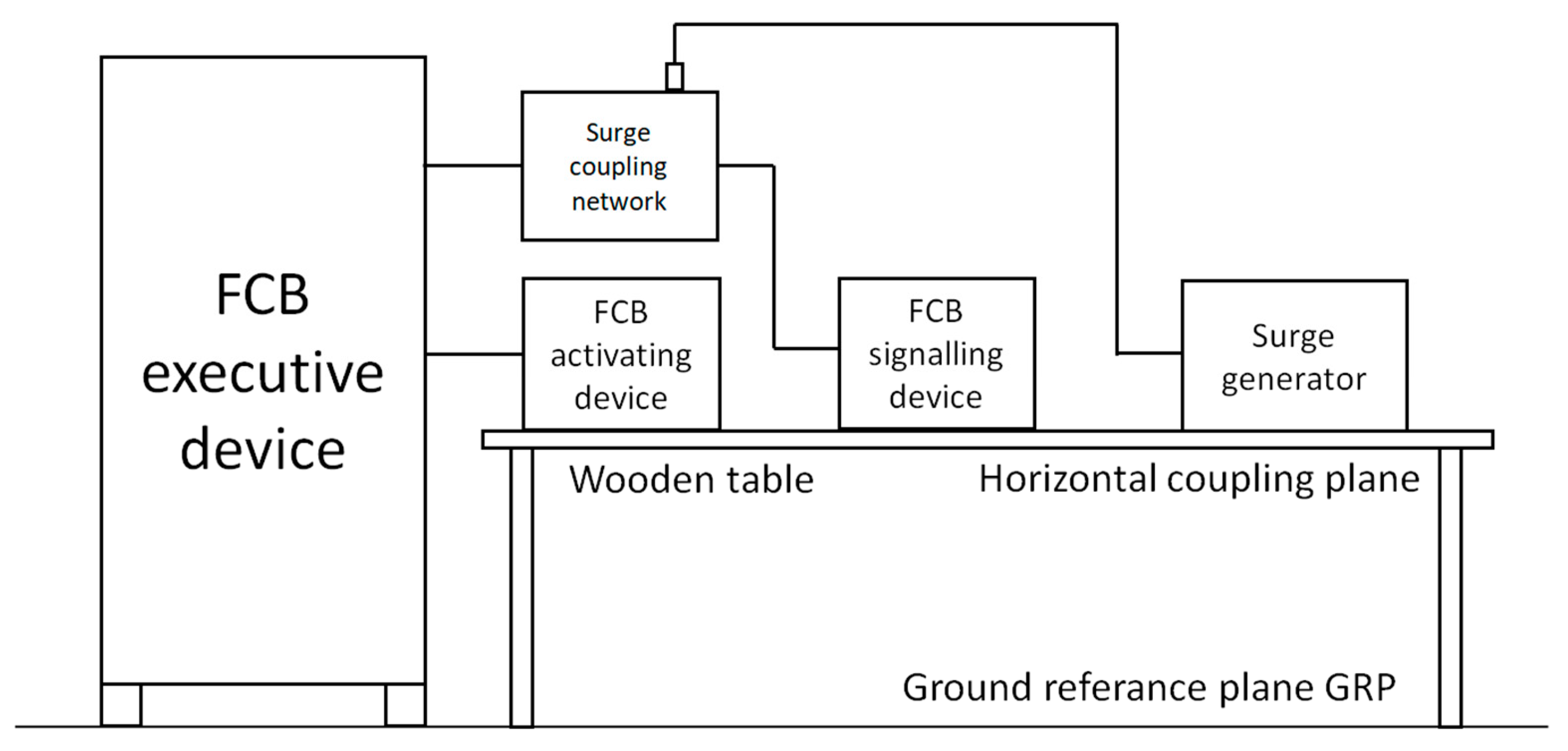
Figure 17.
A view of a sample of the FCB executive devices (sample no. 4) after testing the degree of protection of the enclosure; negative test result, and dust has penetrated into the enclosure, preventing proper operation.
Figure 17.
A view of a sample of the FCB executive devices (sample no. 4) after testing the degree of protection of the enclosure; negative test result, and dust has penetrated into the enclosure, preventing proper operation.
Figure 18.
A view of an example of a sample of the FCB activating device after environmental and EMC testing positive; the actuator worked properly despite visible corrosion marks (on screws and connections).
Figure 18.
A view of an example of a sample of the FCB activating device after environmental and EMC testing positive; the actuator worked properly despite visible corrosion marks (on screws and connections).
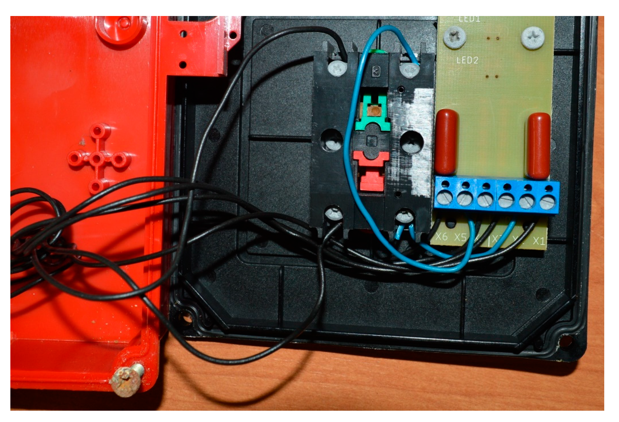
Figure 19.
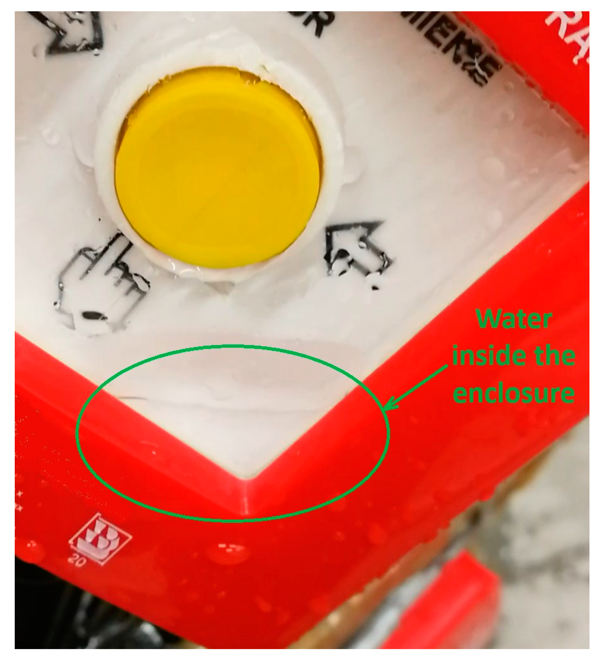
A view of a sample no. 36 of the FCB activating device after testing the degree of protection of the enclosure (IP54 enclosure rating); negative test result, and water entered the enclosure and prevented the proper operation (green circle).
Figure 19.
A view of a sample no. 36 of the FCB activating device after testing the degree of protection of the enclosure (IP54 enclosure rating); negative test result, and water entered the enclosure and prevented the proper operation (green circle).

Table 1.
Reference documents describing the requirements for FCB.
| No. | Product | Reference Document |
|---|---|---|
| 1 | FCB kit (activating, signalling and executive devices) | National Technical Assessment |
| 2 | Activating devices | National Technical Assessment |
| 3 | Signalling devices | National Technical Assessment |
| 4 | Executive devices | Local control: IEC 60947-2 or IEC 60947-3 Remote control: National Technical Assessment |
Table 2.
Basic parameters of samples used for testing for FCB executive devices.
| Sample No. | Rated Voltage of the Main Circuit to Be Disconnected [V] | Rated Current of the Main Circuit [A] | Type of Actuator | Type of Trigger | Rated Voltage of the Trigger [V] | Battery as Backup Power | Delay in Device Operation [s] | Output to the BMS (Building Management System) |
|---|---|---|---|---|---|---|---|---|
| 1 | 230/400 V AC | 50 | FCB1—switch (disconnector) FCB2—circuit-breaker | None (manual control) | None (manual control) | Not | Not | Not |
| 2 | 230/400 V AC | 63 | FCB1—switch (disconnector) FCB2—circuit-breaker FCB3—circuit-breaker | FCB1—shunt trip FCB2—shunt trip FCB3—shunt trip | 24 V DC 230 V AC 230 V AC | Yes | Yes (5 s) | Not |
| 3 | 230/400 V AC | 63 | FCB1—circuit-breaker FCB2—circuit-breaker FCB3—contactor FCB4—switch (disconnector) | FCB1—shunt trip FCB2—shunt trip FCB3—undervoltage trip FCB4—shunt trip | 230 V AC 230 V AC 230 V AC 230 V AC | Not | Yes (5 s) | Yes |
| 4 | 230/400 V AC | 100 | FCB1—switch (disconnector) | None (manual control) | None (manual control) | Not | Not | Not |
| 5 | 230/400 V AC | 50 | FCB1—circuit-breaker FCB2—circuit-breaker | FCB1—shunt trip FCB2—shunt trip | 24 V DC 24 V DC | Yes | Not | Not |
| 6 | 230/400 V AC | 63 | FCB1—switch (disconnector) | None (manual control) | None (manual control) | Not | Not | Not |
Table 3.
Basic parameters of samples used for testing for FCB signalling devices.
| Sample No. | Nominal Supply Voltage [V] | LED Rated Power [W] | Type of Cable for Connection to FCB Executive Device |
|---|---|---|---|
| 1 | 230 V AC | 5 | 2 × 1.5 mm2 |
| 2 | 24 V DC | 2 | 2 × 1.5 mm2 |
| 3 | 24 V DC | 5 | 2 × 2.5 mm2 |
| 4 | 24 V DC | 1 | 2 × 2.5 mm2 |
Table 4.
Basic parameters of samples used for testing for FCB activating devices.
| Sample No. 1 | Type of Switch | Type of Switching Element NO (Normal Open) or NC (Normal Close) | Nominal Supply Voltage [V] | Type of Cable for Connection to FCB Executive Device | Is Cable for Connection to FCB Executive Device Monitored (Short-Cut or Interruption Signalling)? |
|---|---|---|---|---|---|
| 1, 2, 3, 4, 5, 6, 7, 8 | A | NO | 24 V DC | 5 × 1.5 mm2 | Yes |
| 9, 10, 11, 12 | B | NO | 24 V DC | 5 × 1.5 mm2 | Yes |
| 13, 14, 15, 16, 17, 18 | A | NO | 230 V AC | 5 × 2.5 mm2 | Not |
| 19, 20, 21 | B | NC | 230 V AC | 5 × 2.5 mm2 | Not |
| 22, 23, 24 | B | NO | 230 V AC | 5 × 2.5 mm2 | Not |
| 25, 26, 27, 28, 29, 30, 31, 32, 33 | A | NO | 24 V DC | 5 × 2.5 mm2 | Yes |
| 34, 35, 36 | B | NO | 24 V DC | 5 × 2.5 mm2 | Yes |
1 Single samples were used interchangeably for specific environmental and EMP tests.
Table 5.
Proposed dimensions of the FCB activating device based on EN 54-11.
| Parameter | Marking | Dimensions |
|---|---|---|
| Height of the faceplate | a | 85 ≤ a ≤ 135 mm |
| Width of the faceplate | b | 85 ≤ a ≤ 135 mm |
| Height-to-width ratio | a/b | 0.95 ≤ a/b ≤ 1.05 |
| Height of the operating area | c | 0.5 × a ± 10 mm |
| Width of the operating area | d | 0.5 × a ± 10 mm |
| Height-to-width ratio | c/d | 0.95 ≤ c/d ≤ 1.05 |
Table 6.
Environmental classes—a testing scheme with the severity of conditioning.
| Parameter | Activating Devices | Signalling Devices | Executive Devices | Test Method and Test Equipment According to | |||
|---|---|---|---|---|---|---|---|
| Environmental class | 1 | 2 | 1 | 2 | 1 | 2 | - |
| Operating temperature range [°C] | −10 ÷ +55 | −25 ÷ +75 | −5 ÷ +40 | −25 ÷ +75 | −5 ÷ +40 | −25 ÷ +75 | IEC 60068-2-1:2007 [24] and IEC 60068-2-78:2012 [25] Weisstechnik Climatic chamber 1.8 × 1.5 × 1.5 m |
| Maximum relative humidity [%] | 93 ± 3 | IEC 60068-2-78:2012 Weisstechnik Climatic chamber 1.8 × 1.5 × 1.5 m | |||||
| Possibility of installation indoor (I)/outdoor (O) | I | O | I | O | I | O | - |
| IP degree of protection of the enclosure | IP30 | IP54 | IP30 | IP54 | IP30 | IP54 | IEC 60529:1989 [26] ED&D ϕ2.5 mm tool, ITS dust chamber ED&D spray nozzle |
| Vibration (operational) | Frequency range (10 ÷ 150) Hz, Acceleration amplitude 0.1 g Number of axes 3, Rate of frequency variation 1 octave/min, Number of frequency variation cycles for axis 1 | IEC 60068-2-6:2007 [27] OTSTechnik Vibration test table 1.2 × 1.2 m | |||||
| Vibration (endurance) | Frequency range (10 ÷ 150) Hz, Acceleration amplitude 0.5 g Number of axes 3, Rate of frequency variation 1 octave/min, Number of frequency variation cycles for axis 20 | IEC 60068-2-6:2007 OTSTechnik Vibration test Table 1.2 × 1.2 m | |||||
| Mechanical impact (operational) | Impact energy (0.5 ± 0.04) J, Number of impacts on available point 3 | IEC 60068-2-75:2014 [28] PTL-Instruments Impact hammer | |||||
| Shock (operational) | Pulse shape: semi-sinusoidal, pulse duration: 6 ms, maximum acceleration: 10 × (100–20 M) m/s2 Number of strokes per axis: 6. Number of pulses per axis: 3 | - | IEC 60068-2-27:2008 [29] Shaker on OTSTechnik vibration test table 1.2 × 1.2 m | ||||
| Corrosive atmosphere SO2 (endurance) | SO2 concentration by volume (25 ± 5) ppm, Temperature (25 ± 2) °C at (95 ± 3)% humidity, Exposure time 21 days. | - | SO2 concentration 0.67 Vol.-% 1 cycle stage Temperature 40 ± 3 °C Humidity approx. 100% Time 8 h 2nd cycle stage Temperature 23 ± 5 °C Humidity ≤ 75% Time 16 h Number of cycles 20 cycles | - | SO2 concentration 0.67 Vol.-% 1 cycle stage Temperature 40 ± 3 °C Humidity approx. 100% Time 8 h 2nd cycle stage Temperature 23 ± 5 °C Humidity ≤ 75% Time 16 h Number of cycles 20 cycles | ISO 22479:2019 [30] VLM Corrosion chamber 1.8 × 1.2 × 1.2 m and IEC 60068-2-42:2003 [31] Weisstechnik Corrosion chamber 1.8 × 1.5 × 1.5 m | |
Table 7.
Test results of empirical tests for FCB executive devices.
| Sample No. | Control | Main Part of the Executive Device | A Type of Trigger for the Executive Device | Minimum Trigger Voltage [V] | Start-Up Time of the Executive Device [s] (max. 10 s) | Was There No Permanent Arc or Flashover between the Poles or between the Poles and the Base during the Tripping Test? | Damage after Environmental Tests | Damage after the EMC Tests | Obtained IP Degree of Protection of the Housing 3—ϕ2.5 mm Tool Protected 4—Splashing of Water 5—Dust Protected |
|---|---|---|---|---|---|---|---|---|---|
| 1 | Manual | FCB1—switch (disconnector) FCB2—circuit-breaker | None (manual control) | None (manual control) | 4 | Not | No damage | No damage | IP54 |
| 2 | Remote | FCB1—switch (disconnector) FCB2—circuit-breaker FCB3—circuit-breaker | FCB1—shunt trip FCB2—shunt trip FCB3—shunt trip | 23.8 V DC 220 V AC 219 V AC | 3 | Not | No damage | No damage | IP30 |
| 3 | Remote | FCB1—circuit-breaker FCB2—circuit-breaker FCB3—contactor FCB4—switch (disconnector) | FCB1—shunt trip FCB2—shunt trip FCB3—undervoltage trip FCB4—shunt trip | 219 V AC 218 V AC 218 V AC 221 V AC | 8 | Not | No damage | No damage | IP54 |
| 4 | Manual | FCB1—switch (disconnector) | None (manual control) | None (manual control) | 2 | Not | No damage | No damage | IP30 1 |
| 5 | Remote | FCB1—circuit-breaker FCB2—circuit-breaker | FCB1—shunt trip FCB2—shunt trip | 23.5 V DC 23.4 V DC | 3 | Not | No damage | No damage | IP30 |
| 6 | Manual | FCB1—switch (disconnector) | None (manual control) | None (manual control) | 2 | Not | No damage | No damage | IP30 |
1 IP54 test was originally carried out with negative results; hence, the enclosure was downgraded to IP30 (Figure 11).
Table 8.
Test results of empirical tests for FCB signalling devices.
| Sample No. | Optical Signalling of the Executive Device Activation | Damage after Environmental Tests | Damage after the EMC Tests | The Obtained IP Degree of Protection of the Housing 3—ϕ2.5 mm Tool Protected 4—Splashing of Water 5—Dust Protected |
|---|---|---|---|---|
| 1 | Yes | No damage | No damage | IP54 |
| 2 | Yes | No damage | No damage | IP30 |
| 3 | Yes | No damage | No damage | IP54 |
| 4 | Yes | No damage | No damage | IP54 |
Disclaimer/Publisher’s Note: The statements, opinions and data contained in all publications are solely those of the individual author(s) and contributor(s) and not of MDPI and/or the editor(s). MDPI and/or the editor(s) disclaim responsibility for any injury to people or property resulting from any ideas, methods, instructions or products referred to in the content. |
© 2024 by the authors. Licensee MDPI, Basel, Switzerland. This article is an open access article distributed under the terms and conditions of the Creative Commons Attribution (CC BY) license (https://creativecommons.org/licenses/by/4.0/).
Share and Cite
MDPI and ACS Style
Popielarczyk, T.; Stępień, P.; Chmiel, M.; Iwańska, M. Tests of Fire Circuit Breakers (FCBs) to Assess Their Suitability for Use in Construction Objects. Electronics 2024, 13, 1633. https://doi.org/10.3390/electronics13091633
AMA Style
Popielarczyk T, Stępień P, Chmiel M, Iwańska M. Tests of Fire Circuit Breakers (FCBs) to Assess Their Suitability for Use in Construction Objects. Electronics. 2024; 13(9):1633. https://doi.org/10.3390/electronics13091633
Chicago/Turabian StylePopielarczyk, Tomasz, Paweł Stępień, Michał Chmiel, and Marta Iwańska. 2024. "Tests of Fire Circuit Breakers (FCBs) to Assess Their Suitability for Use in Construction Objects" Electronics 13, no. 9: 1633. https://doi.org/10.3390/electronics13091633
Note that from the first issue of 2016, this journal uses article numbers instead of page numbers. See further details here.