
Frequency Diversity Arc Array with Angle-Distance Two-Dimensional Broadening Null Steering for Sidelobe Suppression


1
College of Information Engineering, Inner Mongolia University of Technology, Hohhot 010051, China
2
Inner Mongolia Key Laboratory of Radar Technology and Application, Hohhot 010051, China
*
Author to whom correspondence should be addressed.
Electronics 2024, 13(9), 1640; https://doi.org/10.3390/electronics13091640
Submission received: 25 March 2024
/
Revised: 20 April 2024
/
Accepted: 22 April 2024
/
Published: 24 April 2024
(This article belongs to the Special Issue Antenna Design and Its Applications)
Abstract
:The frequency diversity arc array (FDAA) improves the structure of the traditional frequency diversity array (FDA) from a linear array structure to an arc array structure, so that the FDAA not only has the advantages of the FDA but also has a large angle and omnidirectional scanning capability. However, when it is equivalent to a linear array, this arc-shaped structure will lead to the phenomenon of inverse density weighting, which leads to a higher sidelobe level of the FDAA beam pattern. In order to solve the problem of a high sidelobe level at a certain position of the FDAA, a frequency diversity arc array with angle-distance two-dimensional broadening null steering is proposed for sidelobe suppression. Using a structural model of the FDAA, the problem of the high sidelobe was analyzed. The linear constrained minimum variance (LCMV) method was used to generate a null with a certain width at the position of the fixed strong sidelobe level in the angle domain and the distance domain of the FDAA beam pattern, to reduce the FDAA sidelobe level. Then, the angle domain and distance domain fixed positions of the FDAA were simulated to generate the null beam pattern. The simulation results verified the effectiveness of this method for reducing the sidelobe level.
1. Introduction
The beam formed by traditional phased array (PA) radar only has angular dependence and is independent of range direction, which has certain limitations. The frequency diversity array (FDA) imposes a small frequency offset between the adjacent array elements of the array, which enables the FDA to form a distance-dependent time-varying transmit pattern in space, which can achieve a two-dimensional matched filtering of the distance angle and greatly improve the radar transmit beam discrimination ability [1]. FDA has attracted the attention of many researchers at home and abroad because of its angle-distance dual dependence, and has very important research value in target tracking, radar detection and wireless communication systems [2].
Beamforming technology mainly concerns the main lobe shape of the antenna pattern and the overall gain level of the sidelobe [3]. It has undergone the representative stages of adaptive beam execution control in the 1960s [4,5], adaptive zero-point control technology in the 1970s [6], and a fast beamforming algorithm research stage [7]. Beamforming technology has been widely used and has become an important part of research. In [8], a frequency-controlled array spot-beamforming method based on a random frequency offset is proposed. A method of using a particle swarm optimization algorithm to optimize the frequency offset of each sub-array is proposed in [9], and a point beam pattern with a high range resolution and low sidelobe level is realized. Refs. [10,11,12] report on the method of using the range-dependent beam of a frequency-controlled array for range-ambiguous clutter suppression. In [13], a method for accurately controlling the beam pattern of a frequency-controlled array by adjusting the frequency offset is proposed. An FDA symmetric beam pattern with a non-uniform frequency offset and density-weighted algorithm is proposed in [14], which reduces the sidelobe level in both the distance and angle dimensions. With the continuous research on beamforming technology, in order to solve the problem whereby some directions in the signal receiving and transmitting space will be affected by strong interference and noise, null beamforming technology in phased-array antenna radar has been proposed and gradually developed. The essence of null beamforming technology is to make the beam pattern form a null at the position of the interference source without affecting the main lobe level. Since the middle of the 20th century, people have begun to study and apply various methods for controlling the zero point of the antenna array pattern [15,16,17]. The commonly used null beamforming techniques include complex weight perturbation [18], array element position perturbation [19], phase perturbation [20], and amplitude perturbation [21]. In [22], an adaptive beamforming algorithm based on the maximum signal-to-interference-plus-noise ratio criterion is proposed, which can form nulls in multiple sidelobe directions. A norm-constrained, robust, adaptive beamforming method is proposed in [23]. By using the norm constraint and the worst-case performance optimization technique, it has excellent robustness to array steering vector error under limited snapshots. In [24], a null broadening robust adaptive beamforming algorithm is proposed. By reconstructing and optimizing the interference plus noise covariance matrix and estimating the true steering vector, the robustness of the algorithm against system error and motion interference is improved. The algorithm can also optimize the beam sidelobe by adjusting the main lobe width. In order to further enhance the robustness of the algorithm, a null broadening technique using a cluster of virtual discrete interference sources instead of a single interference source is proposed [25,26]. [27] propose a null broadening algorithm based on projection transformation and diagonal loading. As part of the continuous research on beamforming technology, this technology has been applied to the frequency diversity array for interference suppression. The scanning angle range of a traditional linear FDA is limited, but in [28], the concept of a frequency diversity arc array (FDAA) is proposed. The FDAA innovates the linear structure of the FDA into an arc structure. The FDAA not only has the advantages of the FDA but can also achieve large-angle and all-round scanning.
The FDAA makes up for the shortcomings of the FDA’s limited scanning range, and the scanning coverage has all-round characteristics. However, when designing the equivalent linear array of the FDAA, the distance between adjacent array elements at the middle position is large, while the distance between array elements on both sides is gradually reduced. This is an anti-density weighting phenomenon, which will lead to a higher sidelobe level of the FDAA beam pattern. In [29], an FDAA pattern synthesis and optimization method based on virtual array elements is proposed, which suppresses the overall sidelobe level of the FDAA through amplitude weighting. In order to suppress the sidelobe at a fixed position of the FDAA, an FDAA with an angle-distance two-dimensional broadening null for sidelobe suppression is proposed in this paper. This method sets zero points at the fixed strong sidelobe positions in the distance domain and the angle domain, so that the strong sidelobe is in the null, while the sidelobe level of the FDAA is suppressed.
The main structure of this paper is as follows: In Section 2, the structural model of the FDAA is analyzed, and the nonlinear frequency offset design of the FDAA presented, forming a more concentrated beam pattern. In Section 3, aiming to resolve the problem of the high sidelobe level of the FDAA beam pattern, the linear constrained minimum variance criterion is used to suppress the sidelobe with the fixed interference signal in the angle domain and distance domain of the FDAA beam pattern. Section 4, the effectiveness of sidelobe suppression by broadening the nulls in the angle domain and distance domain of the FDAA based on the nonlinear frequency offset design is verified by simulation experiments. Finally, the article is summarized in Section 5.
2. FDAA Beam Pattern Synthesis
2.1. FDAA Structural Model
The structural model of the FDAA is shown in Figure 1. Figure 1a is the three-dimensional structure of the FDAA, and Figure 1b is the two-dimensional plane of the FDAA. The FDAA consists of array elements arranged in a circular structure with equal angle intervals by means of transceiver sharing. The accumulated angle of array elements is 360°, the array radius is , and the radiation surface of each array element faces outward. The angle between the two adjacent array elements is , the distance between the two adjacent array elements is , and the aperture angle composed of the activated array elements is .
Suppose there is a far-field target point , and the angle between point and the north direction is . The array element whose beam direction is positive north is set as the reference array element , and then the method of selecting as the reference array element is
where denotes the rounding operation, and represents the angle between two adjacent array elements.
Since each array element in the FDAA has certain limitations on the scanning range of the main beam of the array, the feed system needs to select and activate the array elements in the FDAA according to different scanning angles, so as to select the appropriate array elements to form a set of activated working arrays. The aperture angle formed by the activated working array is expressed as
where represents the coefficient of the beam width, the value range is , is the wavelength, is the speed of light, is the carrier frequency.
According to the characteristics of the arc geometry, the total number of activated array elements is expressed as
where represents the rounding operation.
2.2. FDAA Beampattern Synthesis Analysis with Nonlinear Frequency Offset
After the activated array elements are selected as a set of working arrays, phase compensation is needed to make the array elements project to the equal phase plane, to form an equivalent linear array during beam scanning. In Figure 2, the equivalent linear array diagram of the FDAA is shown. The array element in the north direction is selected as the reference array element , numbered in the clockwise direction of the arc, and numbered in the counterclockwise direction of the arc. According to the geometric relationship, the structural phase compensation of the equivalent linear array formed by the nth working array element is as follows:
Here, represents the spatial distance difference between the reference array element and the nth array element, is the carrier frequency of the central reference array element , and is the speed of light.
Figure 2 shows a working array composed of activated array elements. Assuming that the carrier frequency is , the frequency of the nth activated array element signal is designed as
where is the frequency offset of the nth activated antenna array element. In the design of frequency offset, the Hamming window function and symmetric logarithmic function based on are selected, respectively, to form a more concentrated point beam pattern. is expressed as
The transmitted signal of the nth activated array element is
where represents the complex weighting of the nth array element transmitted signal. Considering far-field approximation, the horizontal distance from the nth activated array element to the far-field observation point can be approximated as
where is the target distance, is the target angle, , and the signal at the far-field observation point can be expressed as
In order to control the target at the desired position , the complex weighted vector can be expressed as
The array factor AF of the FDAA with a non-uniform frequency offset based on a symmetric logarithm can be expressed as
3. Sidelobe Suppression
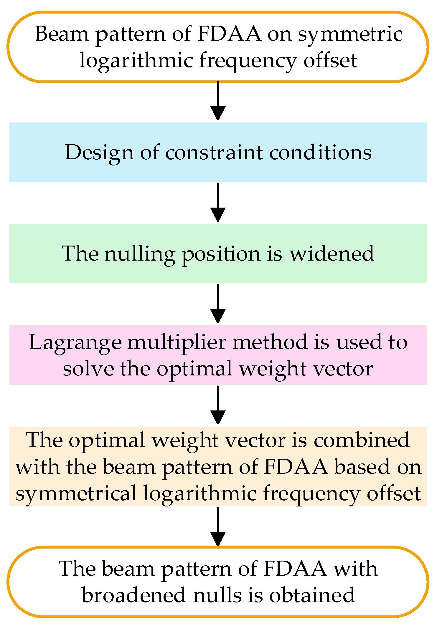
In this section, the reason for the high sidelobe of the FDAA is analyzed. Aiming to resolve the problem of the high sidelobe level at a certain position of the FDAA, an FDAA with angle-distance two-dimensional broadening null steering is proposed for sidelobe suppression. The specific process is shown in Figure 3. Firstly, according to the FDAA beam pattern designed based on symmetric logarithmic frequency offset, the constraints of the angle domain and distance domain are set, respectively. Secondly, the widening of the null position in the angle domain and the distance domain is processed, respectively. Next, the Lagrange multiplier method is used to solve the optimal weight vector. Then, the solved optimal weight vector is combined with the FDAA beam pattern based on the symmetric logarithmic frequency offset. Finally, the beam patterns of the FDAA with two-dimensional broadened nulls in the angle domain and distance domain are obtained, respectively.
3.1. The FDAA Has the Problem of Slightly Higher Sidelobes
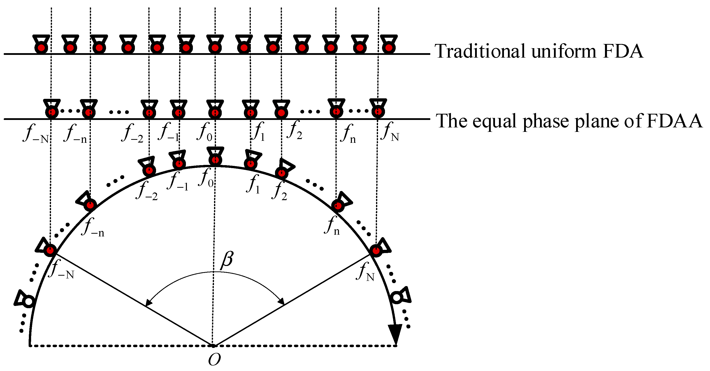
Because the structure of the FDAA is arc-shaped, beam scanning is performed according to the selected activated array elements, which has the characteristics of wide coverage and all-round scanning and can realize real-time monitoring all day and in all weathers. However, when it is projected to the equal phase plane, the distance between adjacent array elements in the middle position is larger, and the distance between adjacent array elements away from the middle position gradually decreases. Figure 4 shows a comparison diagram of the traditional uniform FDA and FDAA array element spacing. Compared with the traditional uniform FDA, the array element spacing of the FDAA presents the characteristics of being “sparse in the middle and dense on both sides”, which is the opposite of the characteristics of being “dense in the middle and sparse on both sides” in density weighting. The array element spacing characteristics presented by the FDAA are an anti-density weighting phenomenon. This phenomenon will lead to a higher sidelobe level in the point beam pattern formed by the FDAA, and a higher sidelobe level will affect the aggregation effect of the main lobe beam to a certain extent.
In order to verify that the inverse density weighting phenomenon will lead to the high sidelobe of the FDAA beam pattern, according to the simulation parameters shown in Table 1, the cross-sections of the FDA and FDAA beam patterns in the angle domain were compared. The simulation results are shown in Figure 5. It can be seen that the sidelobe of the FDAA beam pattern in the angle domain is slightly higher than that of the FDA beam pattern.
3.2. The Angle-Range Two-Dimensional Widening Nulling Method for the FDAA
Since the strong sidelobe level is usually located in a certain area rather than a precise position, in order to ensure that the interference signal position is always in the null, multiple zero constraints can be used at a certain strong sidelobe level position to achieve the purpose of null broadening. In this section, on the basis of selecting the symmetric logarithmic frequency offset as an example for realizing the FDAA spot-beam pattern, the beam pattern of the FDAA with a certain width null is generated at a fixed position in the angle domain and the distance domain, respectively, so that the strong sidelobe interference signal at a certain position is suppressed.
3.2.1. The Angle-Domain Widening Nulling Method for the FDAA
A linearly constrained minimum variance (LCMV) beamformer can be used at the transmitter of antenna radar. The LCMV beamformer can ensure that for the desired signal, a distortion-free signal is obtained, and that a null is formed at the interference signal to suppress the sidelobe level. In the angle domain, the constraint condition is in the form of a set of multiple constraints, which can be expressed as
where , represents the weight vector, , represents the constraint matrix, represents the corresponding constraint response vector, and represents one desired signal and interference signals in , where and are the number of activated array elements. The target direction of the desired signal is , the direction of the interference signal is , , and is an arbitrary value not equal to . Then, the constraint matrix and the constraint response vector are expressed as
The single zero constraint condition is only for the interference signal with a certain direction. However, due to the existence of the steering vector error, the null position is not particularly accurate for the interference signal position. In order to ensure that the interference signal position is always in the null, multiple zero constraints can be used at the position of the strong sidelobe level, so that the width of the null at the strong sidelobe position is increased, to achieve the purpose of null broadening.
Assuming that the null width of the zero position is , the constraint matrix and the corresponding constraint vector are expressed as
The location range of the null is
At this time, the conditional extremum problem can be expressed as
where the autocorrelation data matrix of the signal in the conditional extremum problem is expressed as
is obtained based on the sum of the integrals of the steering vector autocorrelation in the interference zero interval:
The Lagrange multiplier method is used to solve the objective function:
where is the real part and is the Lagrange multiplier factor.
The gradient of Equation (25) is
There is
Substituting Equation (27) into , we obtain
Substituting Equation (28) into Equation (27), the optimal weight vector of the LCMV null broadening algorithm in the angle domain is
Therefore, the complex weighted vector for generating zeros at the interference signal position is
The array factor (AF) of a non-uniform frequency offset FDAA based on using a symmetric logarithm to generate nulls in the angle domain is
3.2.2. The Range-Domain Widening Nulling Method for the FDAA
Similar to the angle domain, in the distance domain, the constraint condition takes the form of a set of multiple constraints, which can be expressed as
where , represents the weight vector, and represent the constraint matrix, represents the corresponding constraint response vector, and in represents a desired signal and interference signals, where ( being the number of activated array elements). The target distance of the desired signal is , the distance position of the interference signal is , , and is an arbitrary value not equal to . Then, the constraint matrix and the constraint response vector are expressed as
Assuming that the null width of the zero position is , the constraint matrix and the corresponding constraint vector are expressed as
The location range of the null is
At this time, the conditional extremum problem can be expressed as
where the autocorrelation data matrix of the signal in the conditional extremum problem is expressed as
is obtained by the sum of the integrals of the steering vector autocorrelation in the interference zero interval:
Using the Lagrange multiplier method, the optimal weight vector of the LCMV null broadening algorithm in the distance domain is obtained as follows:
Therefore, the complex weighted vector for generating zeros at the interference signal position is
The array factor (AF) of the non-uniform frequency offset FDAA based on using the symmetric logarithm to generate nulls in the distance domain is
4. Simulation Analysis
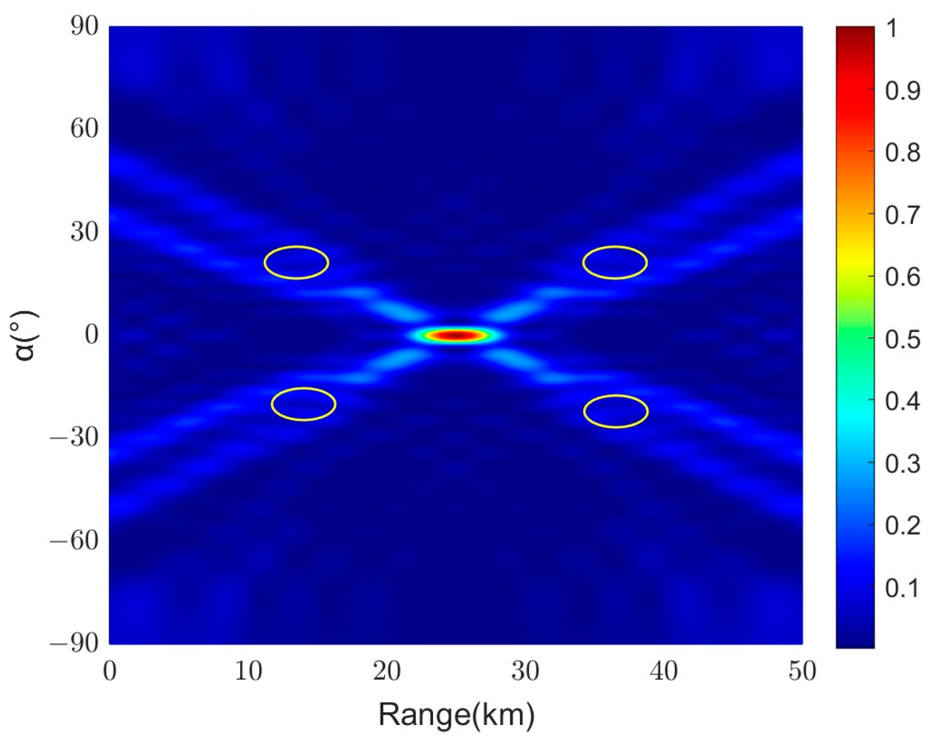
According to the simulation parameters set in Table 1, the FDAA beam pattern is designed based on the Hamming window function, and the nonlinear frequency offset based on the symmetric logarithmic function. In Figure 6a–c, the FDAA beam pattern based on the frequency offset of the hamming window function without nulling is generated. In Figure 7a–c, the FDAA beam pattern without null generation based on the symmetric logarithmic frequency offset is shown. Both Figure 6a and Figure 7a show a clear point beam pattern in the angle-distance two-dimensional domain. In the distance domain, the comparison between Figure 6b and Figure 7b shows that the main lobe beam width of the FDAA beam pattern based on the frequency offset of the Hamming window function is wider. In the angle domain, the comparison between Figure 6c and Figure 7c shows that although the FDAA beam pattern based on the frequency offset of the Hamming window function has little effect on the sidelobe level at the position far from the main lobe beam, the sidelobe level near the main lobe position is not much different from that of Figure 7c. On the whole, the focusing effect of the FDAA beam pattern based on the symmetric logarithmic frequency offset is better. Therefore, the FDAA beam pattern based on the symmetric logarithmic frequency offset is selected for null generation, to achieve the purpose of suppressing the strong sidelobe at a certain position.
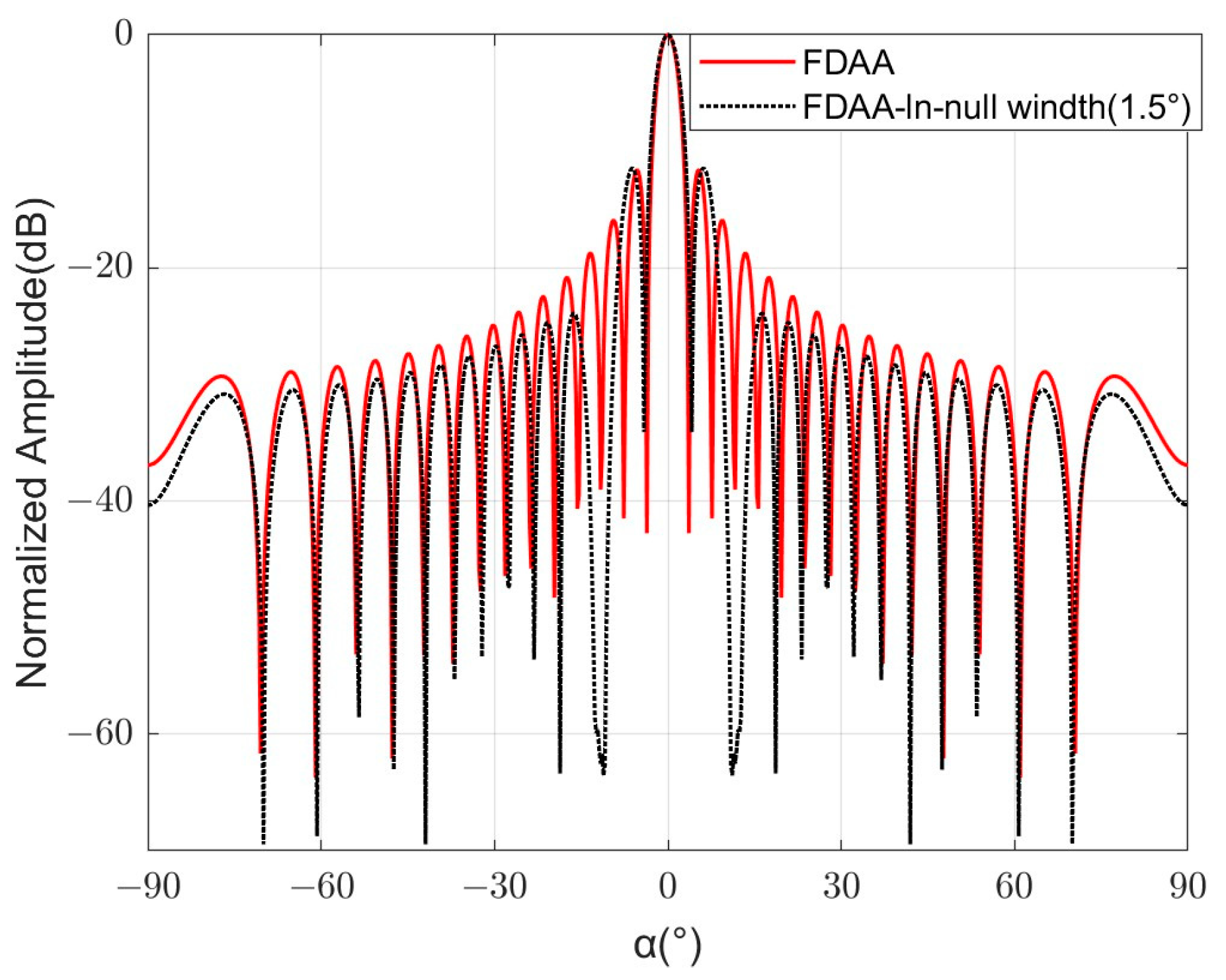
In order to suppress the strong sidelobe interference signal at a certain position in the angle domain, a null with a certain width is generated at the fixed angle position of the FDAA beam pattern. Figure 8 shows an FDAA beam pattern based on a symmetric logarithmic frequency offset angle domain with a null width of 1.5°. In the angle domain, the positions of the nulls are set at −12.5°, −11.75°, −11°, 11°, 11.75°, and 12.5°, respectively. Compared to Figure 7a, it can be seen that the highlight at the angle positions of −12.5°, −11.75°, −11°, 11°, 11.75°, and 12.5° becomes blurred, which indicates that the sidelobe level of the null position is suppressed to a certain extent. The position marked in the Figure 8 is the null generated at the position of strong sidelobe interference. In order to more clearly demonstrate the generation of nulls, in Figure 9, a comparison of the angle domain patterns with a null width of 1.5° and no null is shown. By comparing the beam profile generated by the FDAA with a null width of 1.5° in the angle domain with the beam profile without null generation, it can be seen that the beam profile arising from null generation produces a null depth of about −62 dB at the −12.5°, −11.75°, −11°, 11°, 11.75°, and 12.5° positions, and that the strong sidelobe level at these positions is suppressed.
Figure 10 shows the beam pattern of the FDAA based on the symmetric logarithmic frequency offset angle domain with a null width of 3°. In the angle domain, the position of the nulling is set at −13°, −11.5°, −10°, 10°, 11.5°, and 13°, respectively. It can be seen that the brightness at the angle positions of −13°, −11.5°, −10°, 10°, 11.5°, and 13° becomes lighter, and the position marked on the Figure 10 is the nulling generated when the nulling width is 3°. In Figure 11, a comparison of the pattern of the angle domain with a null width of 3° and the pattern without a null is shown. It can be seen that the beam profile arising from nulling generates a null with a depth of about −48 dB at −13°, −11.5°, −10°, 10°, 11.5°, and 13°. When comparing Figure 9 and Figure 11, it can be found that Figure 11 has a large null width but its null depth is shallower than that in Figure 9. Therefore, the simulation results show that the strong sidelobe of the FDAA can be suppressed by generating nulls at the fixed angle position of the FDAA beam pattern.
Next, a null with a certain width is generated at a fixed position in the distance domain of the FDAA beam pattern. Figure 12 shows an FDAA beam pattern based on a symmetric logarithmic frequency offset with a null width of 1.5 km in the distance domain. In the range domain, the positions of the fixed nulls are set at 12 km, 12.75 km, 13.5 km, 36.5 km, 37.25 km, and 38 km, respectively. It can be seen that a concave with a certain width is formed at the fixed distance position, and the concave extends to a position away from the main lobe beam with the distribution of sidelobes. The position marked in the Figure 12 is the null formed by the strong sidelobe interference position in the range domain. In Figure 13, a comparison of the range domain patterns with a null width of 1.5 km and no null is drawn. It can be seen that a null with a depth of about −67 dB is generated at the 12 km, 12.75 km, 13.5 km, 36.5 km, 37.25 km, and 38 km positions.
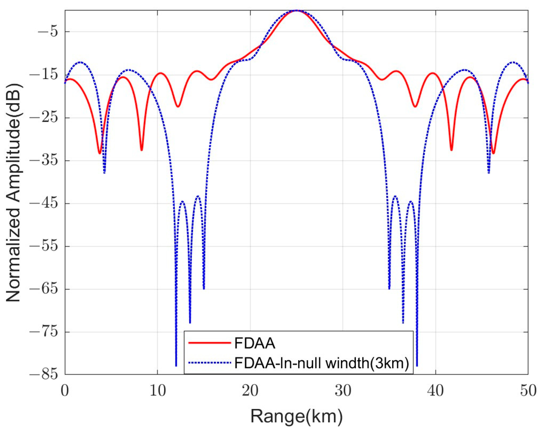
Figure 14 shows an FDAA beam pattern based on a symmetric logarithmic frequency offset with a null width of 3 km in the distance domain. In the distance domain, the positions of the fixed nulls are set at 12 km, 13.5 km, 15 km, 35 km, 36.5 km, and 38 km, respectively. It can be seen that the notch formed at the corresponding distance position is similar to that in Figure 12, but the area of the notch is slightly larger than that in Figure 12. The position marked in the Figure 14 is the null generated when the null width in the distance domain is 3 km. In Figure 15, a comparison of the range domain pattern with a null width of 3 km and no null is drawn. It can be seen that a null with a depth of about −49 dB is generated at the 12 km, 13.5 km, 15 km, 35 km, 36.5 km, and 38 km positions. However, by comparing Figure 13 and Figure 15, it can be found that when the width of the null is wider, the null depth generated will become shallow, so the appropriate null width should be selected to suppress the sidelobe at a certain position. As such, the simulation results show that the null generated at a fixed distance position of the FDAA beam pattern can suppress the strong sidelobe of the FDAA and reduce interference with the main lobe beam.
5. Conclusions
The FDAA not only has the advantages of the FDA but can also achieve a large field of view and all-round scanning characteristics. However, the inverse density weighting phenomenon caused by the FDAA will lead to a higher sidelobe level of the FDAA. In order to suppress the strong sidelobe level interference at a certain position, an FDAA with angle-distance two-dimensional widening null guidance is proposed for sidelobe suppression. The linear constrained minimum variance method is used to generate the nulls. By setting constraints, the Lagrange multiplier method is used to solve the optimal weight vector. The optimal weight vector is combined with the FDAA beam pattern that does not generate the nulls. A beam pattern with a certain width of nulls can be generated at the strong sidelobe interference position in the angle domain and the distance domain. This method can suppress the strong sidelobe level at a fixed position and reduce the strong sidelobe interference signal of the FDAA at the angle-distance position under the premise that the main lobe beam is almost unaffected. According to the simulation results, it is effective to generate nulls at fixed positions in the angle domain and the distance domain to reduce the strong sidelobe level at this position. In the future, this method will continue to be optimized and improved, and new methods will be applied to frequency diversity arc arrays to improve the efficiency and accuracy of radar antennas.
Author Contributions
Conceptualization, W.X.; methodology, W.X.; software, W.X. and Y.T.; validation, W.X. and P.H.; formal analysis, Y.T.; investigation, W.X. and Y.T.; resources, W.X. and W.T.; data curation, Y.T.; writing—original draft preparation, W.X. and Y.T.; writing—review and editing, W.X. and P.H.; visualization, P.H.; supervision, W.T. and Y.Q.; project administration, W.T. and P.H.; funding acquisition, W.X. and P.H. All authors have read and agreed to the published version of the manuscript.
Funding
This research was supported by the National Natural Science Foundation of China under grant numbers 62071258 and U22A2010.
Data Availability Statement
The data presented in this study are available in this article.
Conflicts of Interest
The authors declare no conflicts of interest.
References
- Lan, L.; Liao, G.; Xu, J.; Huang, Y. Research on FDA-MIMO Radar Non-adaptive Beamforming Against Mainlobe Deception Jamming. Signal Process 2019, 35, 944–950. [Google Scholar]
- Ahmad, Z.; Chen, M.; Bao, S.D. Beampattern Analysis of Frequency Diverse Array Aadar: A Review. J Wirel. Com Netw. 2021, 189, 4401. [Google Scholar]
- Xu, D.; He, R.; Shen, F. Robust Beamforming with Magnitude Response Constraints and Conjugate Symmetric Constraint. IEEE Commun. Lett. 2013, 17, 561–564. [Google Scholar] [CrossRef]
- Howells, P.W. Intermediate Frequency Sidelobe Canceller. U.S. Patent 3202990, 24 August 1965. [Google Scholar]
- Capon, J. High-Resolution Frequency-Wavenumber Spectrum Analysis. Proc. IEEE 1969, 57, 1408–1418. [Google Scholar] [CrossRef]
- Frost, O. An Algorithm for Linearly Constrained Adaptive Array Processing. Proc. IEEE 1972, 60, 926–935. [Google Scholar] [CrossRef]
- Reed, I.S.; Mallett, J.D.; Brennan, L.E. Rapid Convergence Rate in Adaptive Arrays. IEEE Trans. Aerosp. Electron. Syst. 1974, 10, 853–863. [Google Scholar] [CrossRef]
- Liu, Y.; Huang, R.; Wang, L.; Nehorai, A. The Random Frequency Diverse Array: A New Antenna Structure for Uncoupled Direction-Range Indication in Active Sensing. IEEE J. Sel. Top. Signal Process. 2017, 11, 295–308. [Google Scholar] [CrossRef]
- Xu, Y.; Shi, X.; Li, W.; Xu, J.; Huang, L. Low-Sidelobe Range-Angle Beamforming with FDA Using Multiple Parameter Optimization. IEEE Trans. Aerosp. Electron. Syst. 2019, 55, 2214–2225. [Google Scholar] [CrossRef]
- Antonik, P.; Wicks, M.; Griffiths, H.; Baker, C. Range Dependent Beamforming Using Element Level Waveform Diversity. In Proceedings of the 2006 International Waveform Diversity & Design Conference, Lihue, HI, USA, 22–27 January 2006; pp. 1–6. [Google Scholar]
- Secmen, M.; Demir, S.; Eker, T. Frequency Diverse Array Antenna with Periodic Time Modulated Pattern in Range and Angle. In Proceedings of the IEEE Radar Conference, Waltham, MA, USA, 17–20 April 2007; pp. 427–430. [Google Scholar]
- Huang, J.; Tong, K.; Woodbridge, K.; Baker, C. Frequency Diverse Array: Simulation and Design. In Proceedings of the 2009 IEEE Radar Conference, Pasadena, CA, USA, 4–8 May 2009; pp. 1–4. [Google Scholar]
- Zhuang, L.; Liu, X.; Yu, W. Precisely Beam Steering for Frequency Diverse Arrays Based on Frequency Offset Selection. In Proceedings of the 2009 International Radar Conference, Pasadena, CA, USA, 4–8 May 2009; pp. 1–4. [Google Scholar]
- Xu, W.; Zhang, L.; Bi, H.; Huang, P.; Tan, W. FDA Beampattern Synthesis with Both Nonuniform Frequency Offset and Array Spacing. IEEE Antennas Wirel. Propag. Lett. 2021, 20, 2354–2358. [Google Scholar] [CrossRef]
- Shpak, D. A Method for the Optimal Pattern Synthesis of Linear Arrays with Prescribed Nulls. IEEE Trans Antennas Propag. 1996, 44, 286–294. [Google Scholar] [CrossRef]
- Er, M.H. Linear Antenna Array Pattern Synthesis with Prescribed Broad Nulls. IEEE Trans. Antennas Propag. 1990, 38, 1496–1498. [Google Scholar] [CrossRef]
- Carlson, B.; Willner, D. Antenna Pattern Synthesis Using Weighted Least Squares. IEEE Proc. H 1992, 139, 11–16. [Google Scholar] [CrossRef]
- Shore, R. A Unified Treatment of Nulling in Linear Array Patterns with Minimized Weight Perturbations. Antennas Propag. Soc. Int. Symp. 1982, 20, 703–706. [Google Scholar]
- Hejres, J. Null Steering in Phased Arrays by Controlling the Positions of Selected Elements. IEEE Trans. Antennas Propag. 2004, 52, 2891–2895. [Google Scholar] [CrossRef]
- Steyskal, H. Simple Method for Pattern Nulling by Phase Perturbation. IEEE Trans. Antennas Propag. 1983, 31, 163–166. [Google Scholar] [CrossRef]
- Yashehyshyn, Y.; Starszuk, G. Investigation of A Simple Four-Element Steering Antenna Array. IEEE Proc.-Microw. Antennas Propag. 2005, 152, 92–96. [Google Scholar] [CrossRef]
- Applebaum, S. Adaptive Arrays. IEEE Trans. Antennas Propag. 1976, 24, 585–598. [Google Scholar] [CrossRef]
- Li, H.; Wang, K.; Wang, C.; He, Y.; Zhu, X. Robust Adaptive Beamforming Based on Worst-Case and Norm Constraint. Int. J. Antennas Propag. 2015, 2015, 765385. [Google Scholar] [CrossRef]
- Fan, Z.; Liang, G.; Wang, Y. A Null Broadening Robust Adaptive Beamforming Algorithm. J. Electron. Inform. 2013, 11, 2764–2770. [Google Scholar]
- Mailloux, R. Covariance Matrix Augmentation to Produce Adaptive Array Pattern Troughs. IEEE Antennas Propag. Soc. Int. Symp. 1995, 1, 102–105. [Google Scholar]
- Zatman, M. Production of Adaptive Array Troughs by Dispersion Synthesis. Electron. Lett. 1995, 31, 2141–2142. [Google Scholar] [CrossRef]
- Li, W.; Mao, X.; Sun, Y. A New Beamforming Null Broadening Algorithm. Electron. Inform. 2014, 36, 2882–2888. [Google Scholar]
- Deng, Z.; Xu, W.; Huang, P.; Tan, W.; Qi, Y. Frequency Diverse Arc Array Beampattern Synthesis Analysis with Nonlinear Frequency Offsets. Prog. Electromagn. Res. Lett. 2023, 110, 109–116. [Google Scholar] [CrossRef]
- Xu, W.; Deng, Z.; Huang, P.; Tan, W.; Gao, Z. Beampattern Synthesis and Optimization for Frequency Diverse Arc Array Based on the Virtual Element. Electronics 2023, 12, 2231. [Google Scholar] [CrossRef]
Figure 1.
Structure model of the FDAA. (a) The three-dimensional structure of the FDAA. (b) The two-dimensional plane of the FDAA.
Figure 1.
Structure model of the FDAA. (a) The three-dimensional structure of the FDAA. (b) The two-dimensional plane of the FDAA.

Figure 2.
Equivalent linear array of the FDAA.

Figure 3.
Flow chart for our proposal of the angle-distance two-dimensional null widening design.

Figure 4.
Comparison of FDA and FDAA array element spacing.

Figure 5.
Comparison of FDA and FDAA angle domain profiles.

Figure 6.
Beam pattern of the FDAA based on the Hamming window function frequency offset without null generation. (a) Hamming-FDAA. (b) Hamming-FDAA in the range domain. (c) Hamming-FDAA in the angle domain.
Figure 6.
Beam pattern of the FDAA based on the Hamming window function frequency offset without null generation. (a) Hamming-FDAA. (b) Hamming-FDAA in the range domain. (c) Hamming-FDAA in the angle domain.

Figure 7.
Beam pattern of the FDAA based on the Sym-Log frequency offset without null generation. (a) Sym Log-FDAA. (b) Sym Log-FDAA in the range domain. (c) Sym Log-FDAA in the angle domain.
Figure 7.
Beam pattern of the FDAA based on the Sym-Log frequency offset without null generation. (a) Sym Log-FDAA. (b) Sym Log-FDAA in the range domain. (c) Sym Log-FDAA in the angle domain.

Figure 8.
Beam pattern of the FDAA with a 1.5° null width in the angle domain based on the Sym-Log frequency offset.
Figure 8.
Beam pattern of the FDAA with a 1.5° null width in the angle domain based on the Sym-Log frequency offset.

Figure 9.
Comparison of angle-domain patterns with a null width of 1.5° and without nulls.

Figure 10.
Beam pattern of the FDAA with a 3° null width in the angle domain based on the Sym-Log frequency offset.
Figure 10.
Beam pattern of the FDAA with a 3° null width in the angle domain based on the Sym-Log frequency offset.

Figure 11.
Comparison of angle-domain patterns with a null width of 3° and without nulls.

Figure 12.
Beam pattern of the FDAA based on the Sym-Log frequency offset with a 1.5 km null width in the range domain.
Figure 12.
Beam pattern of the FDAA based on the Sym-Log frequency offset with a 1.5 km null width in the range domain.

Figure 13.
Comparison of distance-domain patterns with a null width of 1.5 km and without nulls.

Figure 14.
Beam pattern of the FDAA based on the Sym-Log frequency offset with a 3 km null width in the range domain.
Figure 14.
Beam pattern of the FDAA based on the Sym-Log frequency offset with a 3 km null width in the range domain.

Figure 15.
Comparison of distance-domain patterns with a null width of 3 km and without nulls.


Table 1.
Simulation parameter design.
| Parameter | Symbol | Value |
|---|---|---|
| Frequency offset | 30 KHz | |
| Carrier frequency | 10 GHz | |
| Array element spacing | 0.015 m | |
| Element amount | 100 | |
| Number of activated array elements | 33 | |
| Angle of array | π/2 | |
| Array radius | 0.378 m | |
| Target distance | 25 km | |
| Target angle | 0° |
Disclaimer/Publisher’s Note: The statements, opinions and data contained in all publications are solely those of the individual author(s) and contributor(s) and not of MDPI and/or the editor(s). MDPI and/or the editor(s) disclaim responsibility for any injury to people or property resulting from any ideas, methods, instructions or products referred to in the content. |
© 2024 by the authors. Licensee MDPI, Basel, Switzerland. This article is an open access article distributed under the terms and conditions of the Creative Commons Attribution (CC BY) license (https://creativecommons.org/licenses/by/4.0/).
Share and Cite
MDPI and ACS Style
Xu, W.; Tian, Y.; Huang, P.; Tan, W.; Qi, Y. Frequency Diversity Arc Array with Angle-Distance Two-Dimensional Broadening Null Steering for Sidelobe Suppression. Electronics 2024, 13, 1640. https://doi.org/10.3390/electronics13091640
AMA Style
Xu W, Tian Y, Huang P, Tan W, Qi Y. Frequency Diversity Arc Array with Angle-Distance Two-Dimensional Broadening Null Steering for Sidelobe Suppression. Electronics. 2024; 13(9):1640. https://doi.org/10.3390/electronics13091640
Chicago/Turabian StyleXu, Wei, Ying Tian, Pingping Huang, Weixian Tan, and Yaolong Qi. 2024. "Frequency Diversity Arc Array with Angle-Distance Two-Dimensional Broadening Null Steering for Sidelobe Suppression" Electronics 13, no. 9: 1640. https://doi.org/10.3390/electronics13091640
Note that from the first issue of 2016, this journal uses article numbers instead of page numbers. See further details here.