

Offline Fault Diagnosis for 2-Level Inverter: Short-Circuit and Open-Circuit Detection

Korea Electronics Technology Institute (KETI), 25 Saenari-ro, Bundang-gu, Seongnam-si 13509, Gyeonggi-do, Republic of Korea
*
Author to whom correspondence should be addressed.
Electronics 2024, 13(9), 1672; https://doi.org/10.3390/electronics13091672
Submission received: 23 February 2024
/
Revised: 11 April 2024
/
Accepted: 16 April 2024
/
Published: 26 April 2024
(This article belongs to the Topic Power Converters, 2nd Volume)
Abstract
:Fault detection is very important to improve the reliability of power conversion devices. Faults of power semiconductors can be broadly divided into shorts and opens and are further classified into two types depending on whether there is an internal problem with the switch or anti-parallel diode. In this paper, fault-diagnosis methods for short-circuit and open-circuit states are proposed, respectively. A method of classifying and diagnosing faults by applying a gate signal to each switch is proposed to diagnose short-circuit conditions. This method uses only current magnitude information, which reduces the amount of required information and reduces diagnostic failures due to angle errors and current noise. A method is proposed to detect a faulty switch by applying a voltage vector and comparing the current angle with a lookup table to diagnose an open state. An iterative diagnostic algorithm is proposed to prevent diagnostic failure due to angle error and current noise. The effectiveness of the proposed diagnosis method is verified through experiments and simulations.
1. Introduction
Electric motors are used in various fields, such as electric propulsion systems, fans, and pumps. As interest in greenhouse gas emissions grows, the importance of power conversion devices for driving motors is gradually increasing to increase the system efficiency. In general, methods of driving electric motors are largely divided into a direct online (DOL) that uses the grid voltage as input and a method that uses a voltage source inverter (VSI), which consists of power-device semiconductors. The DOL method does not require a power conversion system because it uses the grid voltage, but it is difficult to apply to systems that have a highly variable speed range because it is difficult to vary the speed of the motor due to the frequency of the grid. Since the method of using VSI uses DC voltage as an input, an additional AC/DC converter is required to offer the DC-link voltage to VSI, but efficient operation of the entire system is possible by changing the current operating points depending on the load condition of the motor.
As electric drive systems become popular, improving the reliability and robustness of the overall system becomes increasingly important to operate the entire system safely. For this, various studies are being conducted to improve the reliability of electric drive systems. Akin et al. proposed a method for monitoring motor system faults through harmonic components of current [1]. Gou Bin et al. proposed a sensor failure diagnosis method using the Extreme Learning Machine (ELM) based on DC-link voltage, phase current, and speed signals [2]. Tanvir et al. used vibration and current signals together to diagnose motor faults [3]. KHAN et al. introduced the main fault spots of DC/DC converters and the corresponding fault diagnosis and fault response operation methods [4]. Karimi et al. proposed the three-leg fault-tolerant converter topologies used in wind energy conversion systems (WECSs) [5]. This method used the field-programmable gate array (FPGA) to diagnose the fault in the converter.
Approximately 30% of faults in electric drive systems throughout industry are due to faults in power devices [6]. Therefore, it is very important to diagnose fault conditions for these power devices to ensure system reliability. In [7], a method was proposed for diagnosing the open fault state of each switch using the current residual vector. In [8], a diagnosis method for a multi-level inverter was proposed using AI technology. This method proposed an effective diagnosis method using a genetic algorithm for faults in each cell that makes up the multi-level system, but it has the disadvantage of being complicated to implement. In [9,10,11,12], the method was proposed to identify faults in each switch using the angle of the rotating current vector when driving an induction motor. This method effectively detects one-phase or two-phase switch faults, but the sequence is complicated because the faults are judged through the judgment criteria of several formulas. In [13], a method for fault tolerance of the DC/DC converter was proposed.
There are various research methods for fault diagnosis of power devices [1,2,3,4,5,6,7,8,9,10,11,12,13,14,15], but most of them are limited to situations where the switch inside the power device is open and an anti-parallel diode is present. However, in reality, the fault states can be divided into three types: short circuit, switch open, and switch/diode open. Therefore, appropriate diagnostic methods for each fault situation are needed. In addition, many conventional research methods diagnose faults based on the current in the synchronous reference, the DQ axis, but there is a possibility of incorrect diagnosis in situations where the synchronization angle is unknown or when there is an error in the synchronization angle. Therefore, in this paper, fault-diagnosis methods for short-circuit and open-circuit states are proposed, respectively. A method of classifying and diagnosing faults by applying a gate signal to each switch is proposed to diagnose short-circuit conditions. The proposed short-circuit fault-diagnosis method uses only current magnitude information, which reduces the amount of information required and reduces diagnostic failures due to angle errors and current noise. A method to diagnose an open state is proposed to detect a faulty switch by applying a voltage vector pulse and comparing the current angle with a lookup table. An iterative diagnostic algorithm is proposed to prevent diagnostic failure due to angle error and current noise. The effectiveness of the proposed diagnosis method is verified through experiments and simulations.
2. Conventional Inverter Fault-Diagnosis Method
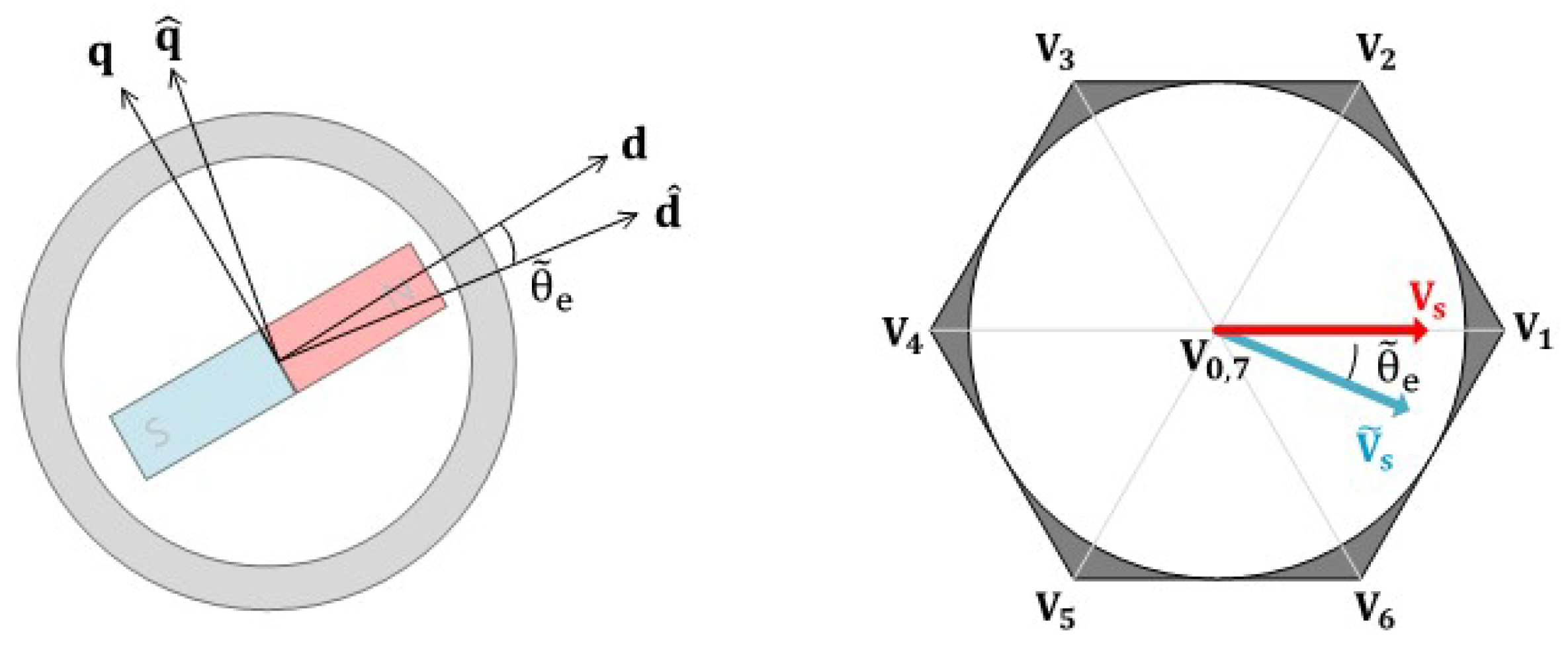
Figure 1 shows a three-phase, two-level inverter. It generally consists of six switches, a DC-link capacitor, a gate driver for driving the switches, and a control board. Through pulse-width modulation (PWM), the voltage required to drive the motor is generated, and speed or current control is performed. Generally, to diagnose a fault in each switch, a voltage vector is applied while rotating by a certain voltage angle, and the fault state of the switch is diagnosed based on the angle of the current. At this time, the synchronization angle, , is used when the voltage vector is applied. To obtain the , the angle sensor, such as a resolver or encoder, is generally used. If there is an error in the , a voltage vector rotated by the angle error, is applied, and an incorrect fault can be diagnosed. Figure 2 shows the change in voltage vector according to . When there is , is applied instead of the vector. Errors in this synchronization angle often occur even when a precise angle sensor is used due to the sensing noise or resolution of sensors. This problem does not occur when driving the induction motor (IM) because there are no magnets in the rotor. However, if there is a magnet in the rotor, such as in a permanent magnet synchronous motor (PMSM), this angle error can cause incorrect fault diagnosis. The difference arises from the fact that in an induction motor, the magnetic flux of the rotor is induced due to the applied current, whereas in a PMSM, the synchronous angle is fixed due to the magnets present in the rotor. Therefore, to expand the existing fault-diagnosis method to PMSM, this angle error must be taken into consideration.
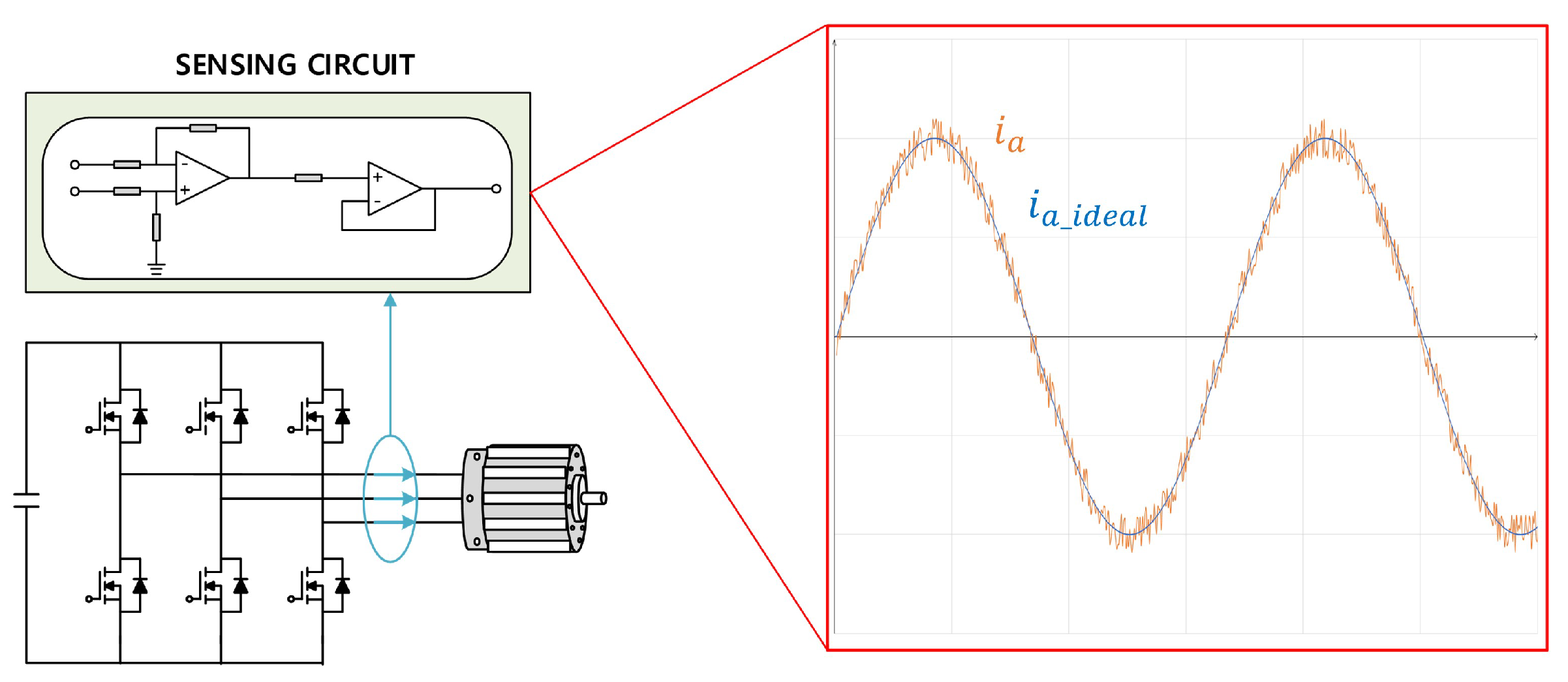
Another factor that interferes with fault diagnosis is current-sensing noise. In general, the voltage vector is applied, and the angle of the current is used to diagnose a fault. At this time, the current angle, , is detected by sensing the phase currents of the motor and converting it to a stationary coordinate frame. In reality, many power conversion devices are driven through PWM switching, so the current noise is inevitable during the current-sensing process. There are a variety of factors that cause such noise, including PWM switching, sensing power ringing, and op-amp nonlinearity. Figure 3 shows noise signals that can occur in a typical current-sensing circuit. When sensing the motor current, there is high-frequency noise in the sensing signal. The formula for obtaining the angle of current is expressed as follows:
where means the current in stationary reference frame, and is the current angle. When the magnitude of the fundamental current is small, this noise causes an incorrect current angle, which causes a misdiagnosis. When current noise exists, noise also exists in the stationary coordinate frame current, and this is expressed as follows:
where and are the current noise in current. This current noise can be reflected in and as in (2), and in this case, when the magnitude of the and is relatively large compared to and , it may cause an error in determining the current angle.
3. Proposed Fault-Diagnosis Method
In the previous section, it was shown that fault diagnosis can be affected by the current angle and current noise. Since the power conversion systems are generally implemented through PWM switching, these problems cannot be avoided. To solve these problems, a new fault-diagnosis method is needed. Several methods have been proposed for diagnosing existing inverter faults, but most of them only deal with cases where the internal switch is open. In addition, since the selection of the applied voltage magnitude is not addressed, discussion on the voltage magnitude is necessary for safe fault diagnosis. In this section, short and open cases are distinguished, and new fault-diagnosis methods are proposed differently for each case.
3.1. Short Circuit
In general, the representative detection method for short circuits is the desaturation protection method [16,17,18]. This is a protection circuit that uses the voltage across the switch to increase depending on the current magnitude, and is used to protect the inverter in a short circuit or overcurrent situation. However, this method alone has the disadvantage of making it difficult to detect the desaturation signal through just B or C-phase switching when the A-phase switch fails. Another method is to detect the current using the voltage induced between the source and the Kelvin source when the current flows through the inverter [16,19]. This method can effectively detect overcurrent and restore the current magnitude, but it is difficult to accurately identify internal parasitic components, and the switch module must have the Kelvin source pin to measure this voltage.
To compensate for the shortcomings of existing methods and effectively detect short-circuit situations, it is necessary to examine the situation when the gate signal of each switch is applied. If the switch of one phase is shorted, the current will flow when the switch of the other phase is turned on. At this time, the gate signal is driven separately for each switch rather than in complementary operation.
Figure 4 shows the current path when only the gate signal is applied when the switch is short. Since the switch is short, when the switch is on, the current can flow between the A and B phases, and through this, the switch short can be detected. In normal conditions, the current is not conducted. However, it is possible to determine a short circuit based on the current. However, as mentioned in the previous section, measuring a current that is too small can result in an incorrect diagnosis due to sensing noise. There are also questions about how to select the duty of each switch. If too large a duty is applied, a very large current may be conducted, which may cause motor rotation or other unexpected problems. Therefore, a detection method that is robust to current-sensing noise while limiting the magnitude of the current is needed.
Table 1 shows the fault switch according to the current direction for each case of the short-circuit diagnosis method. In cases due to the duty application of switches on the same phase, the desaturation protection method is used, but for other phase faults, the fault is diagnosed based on the polarity of the current. With this method, the short circuit can be ideally detected even at a small duty, but in reality, there is a possibility of incorrect diagnosis due to the aforementioned current noise. To avoid such incorrect diagnosis, fault diagnosis should be made only when a current exceeding a certain current level is detected. Figure 5 shows an example of the proposed gate signal excitation method and fault-diagnosis method. Starting with the initial duty, , the current of each phase is determined after the gate signal is applied. At this time, if the magnitude of the current of each phase becomes greater than , the fault of the switch is diagnosed according to the motor current. At this time, if the magnitude of the current is smaller than , the applied duty is increased little by little, and this process is repeated. This entire sequence is repeated 6 times from to switches to detect all faults. This method prevents misdiagnosis due to current noise and enables safe fault diagnosis by preventing overcurrent situations due to initial large duty. Since this method gradually increases the on-duty, the detection time is relatively long, but it can safely and reliably diagnose the short circuit. The accuracy and diagnosis time vary depending on how much the duty is increased each time.
3.2. Open Circuit
In this section, the open-circuit diagnosis method is proposed through voltage vector injection. Figure 6 shows the hodographs in which current can flow in the - coordinate system when each single switch fault occurs. For example, when an open fault occurs in a single switch , the positive current cannot flow, so the area where the current can flow in the - coordinate system appears as the left half plane. Similarly, in the case of an open failure of another switch, the area where the current can flow is the area opposite to the failed switch, as shown in Figure 6. Various methods for diagnosing open faults have been studied based on these principles, but there is a lack of discussion on the magnitude of the injection voltage.
In this paper, an open fault-diagnosis method is proposed to diagnose open faults in power-device switches by injecting voltage vectors with a certain voltage magnitude at electrical angle intervals. The proposed method identifies switch defects by checking a specific current pattern using the characteristic that the current range is limited due to an open-circuit failure of the power switch. The applied voltage vector can be expressed as
where is the amplitude of the injection voltage. When a voltage vector is applied in a healthy state, a current corresponding to the direction of the voltage vector is generated, as shown in Figure 7a. Since the voltage vector is applied in the form of a pulse, the current generated is proportional to the phase resistance of the stator, and the phase matches the voltage vector.
When an open fault occurs in a switch of a power device, the path of the current changes due to the open fault, and the current angle is fixed at a specific voltage vector, so this characteristic can be used to estimate the switch where the open fault occurred. For example, when an open fault of Switch occurs, and a voltage vector from the right half of the - coordinate system is applied, the positive current cannot be generated, so the current angle is fixed to and . In the same way, if an open-circuit failure of another switch occurs, the current vector that can determine the failure can be specified, as shown in Figure 7. Figure 7 shows the current vector that would occur in the event of any single switch open fault. The fault diagnosis angle according to the occurrence of an open fault in a specific switch is shown in Table 2. The faulty switch is identified by comparing it with the fault-diagnosis table and the sampled current vector. Since the proposed open fault-diagnosis method measures the angle of the current, it cannot diagnose when the current is very small or 0. Therefore, the angle for the section where the current is not 0 is stored in the form of a lookup table, and the fault is diagnosed by comparing it with the sampled current angle.
However, as mentioned earlier, the proposed diagnosis method determines the fault angle by sampling the current, which may cause errors due to the current-sensing noise. Therefore, in this paper, a method of repeatedly applying the diagnostic voltage vector is proposed, increasing the magnitude of the voltage until the fault angle results match three times, as shown in Figure 8. First, the initial value of the voltage vector for diagnosis must be determined. If the initial value of the voltage vector is too high, damage to the system may occur, so a small value is selected and increased each time the diagnosis is repeated. After the initial voltage vector value is determined, voltage vector pulses in a total of 12 directions are applied at intervals of /6 to determine the failure of all switches. Open faults are diagnosed by applying a voltage vector and comparing the angle of the sampled current to the fault angle in a lookup table. Since switching noise or small current values can cause diagnostic errors, repeat the diagnosis by increasing the magnitude of the voltage vector until a total of three diagnostic results match.
4. Simulation and Experiment Results
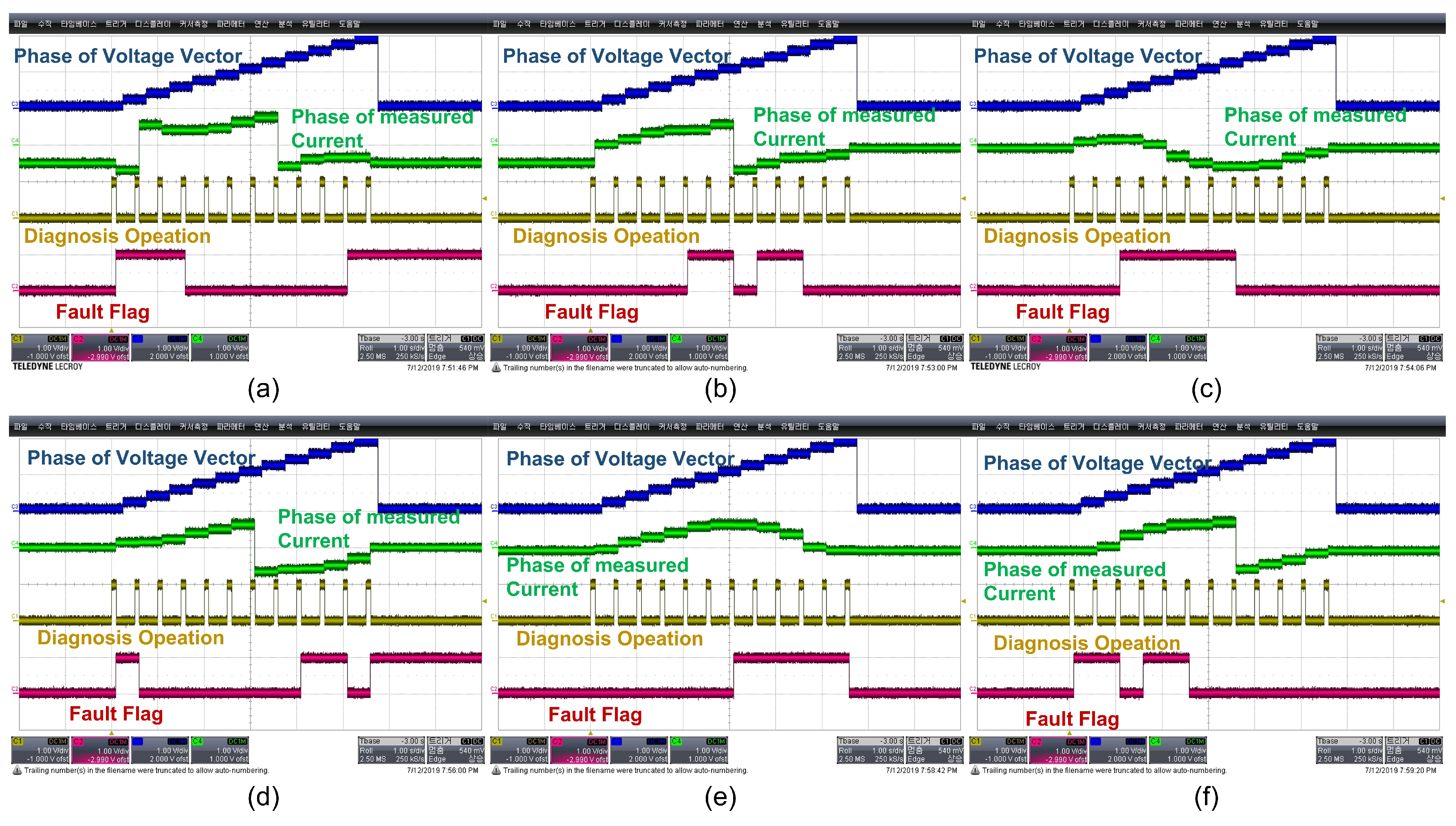
Simulations and experiments are performed to verify the fault-diagnosis algorithm proposed in this paper. Table 3 shows the specifications of the test inverter and motor. The motor and inverter are designed for powertrain use in small electric vehicles. The maximum output of the test inverter is 20 kW, the continuous output is 7.2 kW, and the input DC-link voltage is in the range of 24–65 V. The test motor is a 13 kW induction motor with a maximum torque of 54 Nm and a maximum speed of 7500 rpm. Ti’s TMS320F28335 is used as the MCU for motor control, and the switching frequency was 10 kHz. PSIM S/W is used for simulation to verify the open fault-diagnosis algorithm, and the inverter-motor parameters in Table 3 are used as the simulation parameters. Figure 9 shows the simulation results when Switch 6 is opened. Figure 9a shows the main waveform of the fault-diagnosis algorithm in case of a Switch 6 open fault. As shown in the diagnosis table in Table 2, it can be confirmed that fault flags occur at 0, /6, /2, and 2/3. Figure 9b and Figure 9c show the vectors of input phase voltage and output phase current, respectively. The phase voltage vector is input in all directions at intervals of /6, but due to a switch fault, it can be confirmed that the phase current is only output in the range of 5/6 to /6. Figure 10 shows the test environment of the proposed method using a test motor and inverter. Figure 10a,b show the inverter and motor used in the test. Figure 10c shows the entire test environment and is configured to evaluate the inverter-motor system using a dynamometer. To implement the proposed fault-diagnosis algorithm, the six PWM pulse signals of the MCU are individually activated and deactivated to make the fault state of a specific switch. Assuming each switch, 1 to 6, is in an open fault condition, the MCU blocks the corresponding PWM pulse and sets the switch to always be open. Figure 11 shows the test results of the proposed fault-diagnosis method. Experiments are performed for the fault conditions of every single switch. As described previously, voltage vectors are injected in all directions at /6 intervals, and the fault angle and fault switch are detected using the angle of the current. As a result of the test, the fault is diagnosed within 1.5 s, and the proposed detection algorithm is verified through test results that detect both error states and faulty switches. If the magnitude of the applied voltage is small and fault diagnosis is impossible, an iterative algorithm operates, which may further increase the determination time. However, since the method proposed in this paper is a method of determining faults in the offline state before the inverter operates, increasing the determination time for accurate state diagnosis is not a major problem.
5. Discussion
In this section, the existing method and the proposed method are compared. In general, methods for diagnosing short faults are largely divided into methods using the voltage across the switch [18,20] and methods using the voltage between the emitter and Kelvin emitter [16,19,21]. Both methods use the induced voltage when the motor current flows to diagnose overcurrent and short-circuit conditions when the voltage exceeds a certain voltage. However, since this method operates when the current flows beyond a certain level, it is not appropriate for diagnosing faults in an offline situation. In contrast, the proposed method diagnoses switch faults based on the current generated by applying a very short duty to each switch. Therefore, short errors can be diagnosed and prepared offline in advance.
Conversely, there is a method of applying pulses as an open fault-diagnosis method [22,23]. These methods are similar to the proposed method in that the voltage is applied, and judgment is made based on the angle of the current. In ideal situations, these methods work well, but in the presence of current noise, there is a possibility of incorrect diagnosis due to sensing noise, and there is no separate magnitude selection guide for the applied voltage pulse. Additionally, since most inverter faults are diagnosed in an online situation, there is a lack of explanation as to how much duty should be applied in an offline situation for diagnosis. However, in the proposed method, problems with voltage pulses or current noise can be solved because a very small voltage is applied gradually through iteration. Another method is to use AI to diagnose failures [24], but this is difficult to apply because it is realistically complex.
6. Conclusions
In this paper, a fault-diagnosis method for power switch faults was proposed. Inverter failures were largely divided into short situations and open situations, and detection methods were proposed accordingly. In a short-circuit situation, a small duty is applied to each switch individually, and a fault is detected when the current exceeds a certain current. To detect an open fault, a voltage vector is applied to the inverter, and the fault is diagnosed based on the angle of the current being conducted. In both methods, the magnitude of the duty or voltage vector is gradually increased, and a fault is diagnosed when a current above a certain level is detected, therefore preventing misdiagnosis due to current noise or angle error. This can effectively diagnose faults by complementing the shortcomings of existing methods, and its effectiveness has been verified through simulation and experiment.
Author Contributions
B.J.H. proposed the idea for writing the manuscript. D.Y.H. survey the conventional method related to proposed method. P.J. was in charge of writing and formatting. Y.-S.N. revise the figures needed for our paper. J.-H.K. supervised the overall flow and direction of the paper. All authors have read and agreed to the published version of the manuscript.
Funding
This work was supported by the Korea Institute of Energy Technology Evaluation and Planning (KETEP) grant funded by the Korean government (MOTIE) [Development of High-Efficiency Power Converter based on Multidisciplinary Design and Optimization Platform (20212020800020) and Development of power quality control technology for a large-capacity wind turbine with modular structure (20203030020200)].
Data Availability Statement
Data is unavailable due to privacy or ethical restrictions.
Conflicts of Interest
The authors declare no conflict of interest.
Nomenclature
| DOL | Direct online |
| VSI | Voltage source inverter |
| ELM | Extreme learning machine |
| WECS | Wind energy conversion system |
| FPGA | Field-programmable gate array |
| PWM | Pulse-width modulation |
| PMSM | Permanent magnet synchronous motor |
| Synchronization angle | |
| Angle error in | |
| Current angle | |
| - | Stationary reference frame |
| d-q | Synchronous reference frame |
| DESAT | Desaturation protection signal |
| Initial duty for detecting short situations | |
| Duty increment for short situation detection | |
| Voltage vector for open fault detection | |
| Voltage amplitude of |
References
- Akin, B.; Choi, S.; Orguner, U.; Toliyat, H.A. A simple real-time fault signature monitoring tool for motor-drive-embedded fault diagnosis systems. IEEE Trans. Ind. Electron. 2010, 58, 1990–2001. [Google Scholar] [CrossRef]
- Gou, B.; Xu, Y.; Xia, Y.; Wilson, G.; Liu, S. An intelligent time-adaptive data-driven method for sensor fault diagnosis in induction motor drive system. IEEE Trans. Ind. Electron. 2018, 66, 9817–9827. [Google Scholar] [CrossRef]
- Shifat, T.A.; Hur, J.W. An effective stator fault diagnosis framework of BLDC motor based on vibration and current signals. IEEE Access 2020, 8, 106968–106981. [Google Scholar] [CrossRef]
- Khan, S.S.; Wen, H. A comprehensive review of fault diagnosis and tolerant control in DC-DC converters for DC microgrids. IEEE Access 2021, 9, 80100–80127. [Google Scholar] [CrossRef]
- Karimi, S.; Gaillard, A.; Poure, P.; Saadate, S. FPGA-based real-time power converter failure diagnosis for wind energy conversion systems. IEEE Trans. Ind. Electron. 2008, 55, 4299–4308. [Google Scholar] [CrossRef]
- Wu, F.; Zhao, J. A real-time multiple open-circuit fault diagnosis method in voltage-source-inverter fed vector controlled drives. IEEE Trans. Power Electron. 2015, 31, 1425–1437. [Google Scholar] [CrossRef]
- An, Q.-T.; Sun, L.; Sun, L.-Z. Current residual vector-based open-switch fault diagnosis of inverters in PMSM drive systems. IEEE Trans. Power Electron. 2014, 30, 2814–2827. [Google Scholar] [CrossRef]
- Khomfoi, S.; Tolbert, L.M. Fault diagnosis and reconfiguration for multilevel inverter drive using AI-based techniques. IEEE Trans. Ind. Electron. 2007, 54, 2954–2968. [Google Scholar] [CrossRef]
- Zhang, J.; Zhao, J.; Zhou, D.; Huang, C. High-performance fault diagnosis in PWM voltage-source inverters for vector-controlled induction motor drives. IEEE Trans. Power Electron. 2014, 29, 6087–6099. [Google Scholar] [CrossRef]
- Cherif, B.D.; Bendjebbar, M.; Benouzza, N.; Boudinar, H.; Bendiabdellah, A. A comparative study between two open-circuit fault detection and localization techniques in a threephase inverter fed induction motor. In Proceedings of the 2016 8th International Conference on Modelling, Identification and Control (ICMIC), Algiers, Algeria, 15–17 November 2016. [Google Scholar]
- Sleszynski, W.; Nieznanski, J.; Cichowski, A. Open-transistor fault diagnostics in voltage-source inverters by analyzing the load currents. IEEE Trans. Ind. Electron. 2009, 56, 4681–4688. [Google Scholar] [CrossRef]
- Sleszynski, W.; Nieznanski, J.; Cichowski, A. Real-time fault detection and localization vector-controlled induction motor drives. In Proceedings of the 2005 European Conference on Power Electronics and Applications, Dresden, Germany, 11–14 September 2005. [Google Scholar]
- Cardoso, A.J.M.; Bento, F. Diagnostics and Fault Tolerance in DC–DC Converters and Related Industrial Electronics Technologies. Electronics 2023, 12, 2341. [Google Scholar] [CrossRef]
- Farhadi, M.; Vankayalapati, B.T.; Sajadi, R.; Akin, B. AC Power Cycling Test Setup and Condition Monitoring Tools for SiC-Based Traction Inverters. IEEE Trans. Veh. Technol. 2023, 72, 12728–12743. [Google Scholar] [CrossRef]
- Orlowska-Kowalska, T.; Sobański, P. Simple diagnostic technique of a single IGBT open-circuit faults for a SVM-VSI vector controlled induction motor drive. Bulletin of the Polish Academy of Sciences. Tech. Sci. 2015, 63, 281–288. [Google Scholar]
- Mocevic, S.; Wang, J.; Burgos, R.; Boroyevich, D.; Jaksic, M.; Stancu, C.; Peaslee, B. Comparison and discussion on shortcircuit protections for silicon-carbide MOSFET modules: Desaturation versus Rogowski switch-current sensor. IEEE Trans. Ind. Appl. 2020, 56, 2880–2893. [Google Scholar] [CrossRef]
- Kim, J.; Cho, Y. Overcurrent and short-circuit protection method using desaturation detection of SiC MOSFET. In Proceedings of the 2020 IEEE PELS Workshop on Emerging Technologies: Wireless Power Transfer (WoW), Seoul, Republic of Korea, 15–19 November 2020; pp. 197–200. [Google Scholar]
- Hou, R.; Lu, J.; Quan, Z.; Li, Y.W. A simple desaturation-based protection circuit for GaN HEMT with ultrafast response. IEEE Trans. Power Electron. 2020, 36, 6978–6987. [Google Scholar] [CrossRef]
- Mutlu, A.; Yildirim, D.; Kueruem, B.A. Advantages of Rogowski Coil over Desaturation Method for Leg Short Circuit Detection in Inverters. In Proceedings of the PCIM Europe 2022; International Exhibition and Conference for Power Electronics, Intelligent Motion, Renewable Energy and Energy Management, London, UK, 10–12 May 2022; pp. 1–6. [Google Scholar]
- Aryan, N.P.; Vogler, B.; Ziegler, T. An Innovative Method for Short Circuit Protection of a Three-Phase MOSFET Power Inverter. In Proceedings of the 2023 IEEE Transportation Electrification Conference & Expo (ITEC), Detroit, MI, USA, 21–23 June 2023. [Google Scholar]
- Tanriverdi, O.; Yildirim, D. Analog dv/dt and di/dt Controlled Gate Driver with Self Triggered Hold-at-Zero Algorithm for High Power IGBTs. IEEE Trans. Power Electron. 2023, 39, 1184–1194. [Google Scholar] [CrossRef]
- Sun, T.; Chen, C.; Wang, S.; Zhang, B.; Fu, Y.; Li, J. Inverter open circuit fault diagnosis based on residual performance evaluation. IET Power Electron. 2023, 16, 2560–2576. [Google Scholar] [CrossRef]
- Wang, B.; Feng, X.; Sun, T.; Wang, Z.; Cheng, M. Relative β-axis Residual Voltage Signal Based Fault Detection for Inverter Switch Open-Circuit Failure. IEEE Trans. Power Electron. 2023, 38, 11315–11326. [Google Scholar] [CrossRef]
- Yan, H.; Peng, Y.; Shang, W.; Kong, D. Open-circuit fault diagnosis in voltage source inverter for motor drive by using deep neural network. Eng. Appl. Artif. Intell. 2023, 120, 105866. [Google Scholar] [CrossRef]
Figure 1.
Configuration of 2-level and concept of pulse width modulation when voltage reference is .
Figure 1.
Configuration of 2-level and concept of pulse width modulation when voltage reference is .

Figure 2.
Rotation of voltage vector due to angular error.

Figure 3.
Ideal motor current, and real motor current, including the sensing noise of motor current.
Figure 3.
Ideal motor current, and real motor current, including the sensing noise of motor current.

Figure 4.
The current path (orange) according to the application of the S1 gate signal (blue) when the switch (red) is short-circuited.
Figure 4.
The current path (orange) according to the application of the S1 gate signal (blue) when the switch (red) is short-circuited.

Figure 5.
The proposed gate signal injection method for short fault detection.
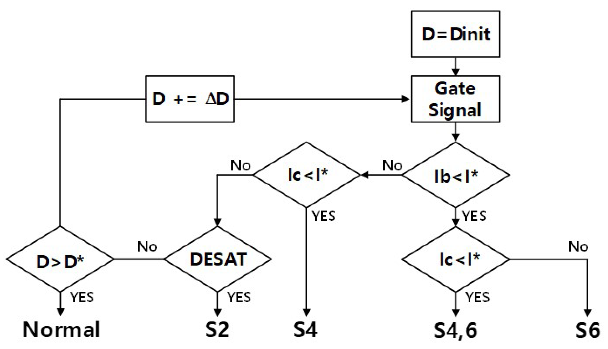
Figure 6.
Power Switch open fault (red) example: (a) inverter circuit, (b) current vector hodographs.
Figure 6.
Power Switch open fault (red) example: (a) inverter circuit, (b) current vector hodographs.

Figure 7.
Current vector according to open fault switch in - coordinate system: (a) normal, (b) , (c) , (d) , (e) , (f) , (g) .
Figure 7.
Current vector according to open fault switch in - coordinate system: (a) normal, (b) , (c) , (d) , (e) , (f) , (g) .

Figure 8.
The proposed voltage vector injection method for open fault detection.
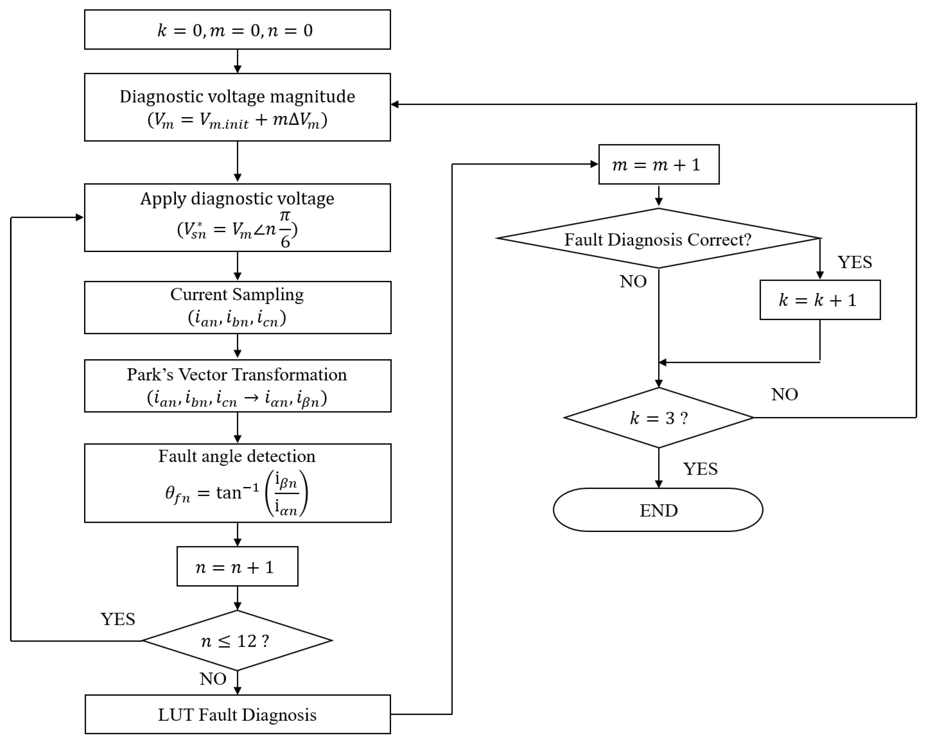
Figure 9.
Simulation results for the proposed method when is open fault: (a) Key waveform, (b) Applied voltage vector, (c) Fault current vector.
Figure 9.
Simulation results for the proposed method when is open fault: (a) Key waveform, (b) Applied voltage vector, (c) Fault current vector.
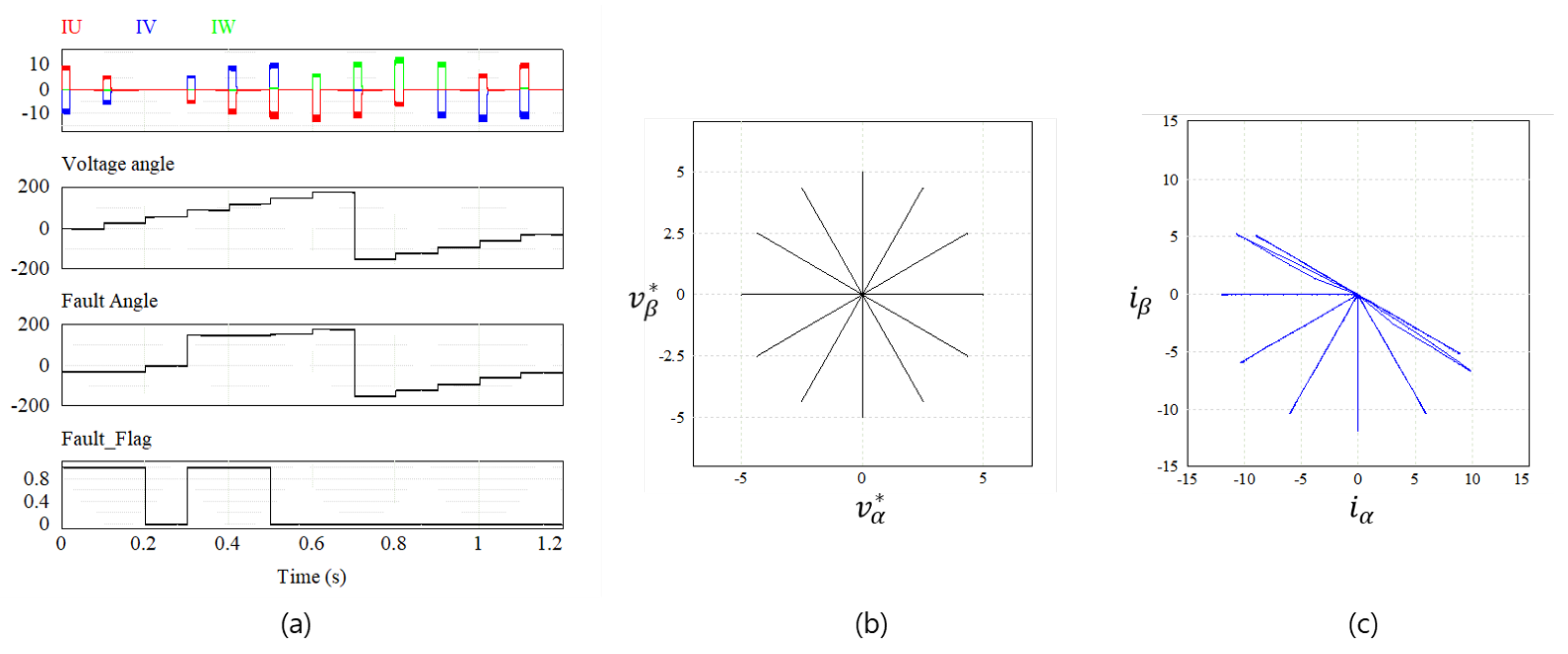
Figure 10.
Experimental environment for the proposed method: (a) Test motor, (b) Test inverter, (c) Test bed.
Figure 10.
Experimental environment for the proposed method: (a) Test motor, (b) Test inverter, (c) Test bed.
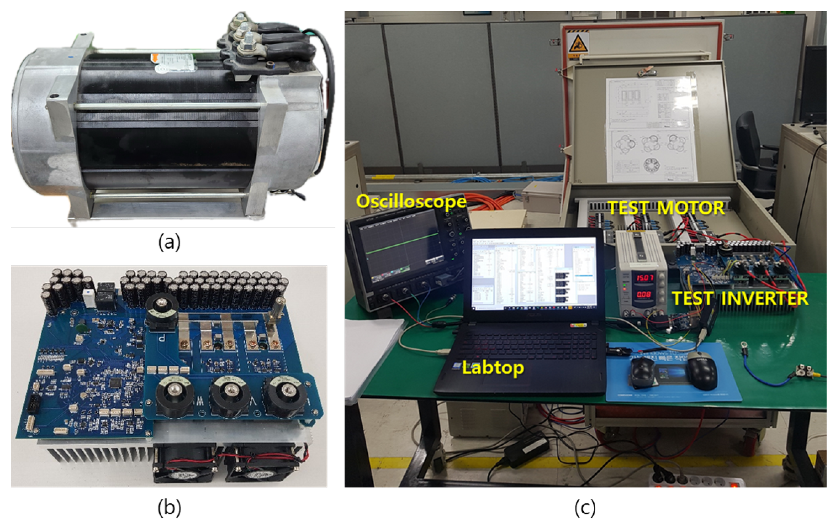
Figure 11.
Experiment results according to each switch open fault: (a) , (b) , (c) , (d) , (e) , (f) .
Figure 11.
Experiment results according to each switch open fault: (a) , (b) , (c) , (d) , (e) , (f) .


Table 1.
Short fault-detection conditions according to gate signal and current direction.
| Gate | Condition | Fault | Gate | Condition | Fault | Gate | Condition | Fault |
|---|---|---|---|---|---|---|---|---|
| DESAT | DESAT | DESAT | ||||||
| DESAT | DESAT | DESAT | ||||||
Table 2.
Open fault-detection conditions according to current angle.
| Voltage Vector | FLT | FLT | FLT | FLT | FLT | FLT |
|---|---|---|---|---|---|---|
| () | - | - | - | - | ||
| () | - | - | - | - | ||
| () | - | - | - | - | ||
| () | - | - | - | - | ||
| () | - | - | - | - | ||
| () | - | - | - | - | ||
| () | - | - | - | - | ||
| () | - | - | - | - | ||
| () | - | - | - | - | ||
| () | - | - | - | - | ||
| () | - | - | - | - | ||
| () | - | - | - | - |
Table 3.
Parameters of the test inverter and induction motor.
| Inverter Parameters | Motor Parameters | ||||
|---|---|---|---|---|---|
| Parameters | Value | Unit | Parameters | Value | Unit |
| Maximum Power | 20 | kW | Motor Type | Induction motor | - |
| Continuous Power | 7.2 | kW | Maximum Power | 13 | kW |
| Maximum Current | 480 | Maximum Torque | 54 | Nm | |
| Continuous Current | 150 | Maximum Speed | 7500 | rpm | |
| DC-link Voltage | 24–65 | Stator Resistance | 4.2 | m | |
| DC-link Capacitance | 470 | F | Stator Inductance | 0.543 | mH |
| Switching Frequency | 10 | kHz | Rotor Resistance | 3.4 | m |
| Cooling Type | Air-Cooled | - | Rotor Inductance | 0.551 | mH |
| Controller | DSP (150 MHz) | - | Mutual Inductance | 0.52 | mH |
Disclaimer/Publisher’s Note: The statements, opinions and data contained in all publications are solely those of the individual author(s) and contributor(s) and not of MDPI and/or the editor(s). MDPI and/or the editor(s) disclaim responsibility for any injury to people or property resulting from any ideas, methods, instructions or products referred to in the content. |
© 2024 by the authors. Licensee MDPI, Basel, Switzerland. This article is an open access article distributed under the terms and conditions of the Creative Commons Attribution (CC BY) license (https://creativecommons.org/licenses/by/4.0/).
Share and Cite
MDPI and ACS Style
Hyon, B.J.; Hwang, D.Y.; Jang, P.; Noh, Y.-S.; Kim, J.-H. Offline Fault Diagnosis for 2-Level Inverter: Short-Circuit and Open-Circuit Detection. Electronics 2024, 13, 1672. https://doi.org/10.3390/electronics13091672
AMA Style
Hyon BJ, Hwang DY, Jang P, Noh Y-S, Kim J-H. Offline Fault Diagnosis for 2-Level Inverter: Short-Circuit and Open-Circuit Detection. Electronics. 2024; 13(9):1672. https://doi.org/10.3390/electronics13091672
Chicago/Turabian StyleHyon, Byong Jo, Dae Yeon Hwang, Pooreum Jang, Yong-Su Noh, and Jin-Hong Kim. 2024. "Offline Fault Diagnosis for 2-Level Inverter: Short-Circuit and Open-Circuit Detection" Electronics 13, no. 9: 1672. https://doi.org/10.3390/electronics13091672
Note that from the first issue of 2016, this journal uses article numbers instead of page numbers. See further details here.