
Joint Base Station Selection and Power Allocation Design for Reconfigurable Intelligent Surface-Aided Cell-Free Networks

6G Research Center, China Telecom Research Institute, Guangzhou 510660, China
*
Author to whom correspondence should be addressed.
Electronics 2024, 13(9), 1688; https://doi.org/10.3390/electronics13091688
Submission received: 27 March 2024
/
Revised: 16 April 2024
/
Accepted: 18 April 2024
/
Published: 26 April 2024
(This article belongs to the Special Issue Energy-Efficient Wireless Solutions for 6G/B6G)
Abstract
:Cell-free (CF) networks can reduce cell boundaries by densely deploying base stations (BSs) with additional hardware costs and power sources. Integrating a reconfigurable intelligent surface (RIS) into CF networks can cost-effectively increase the capacity and coverage of future wireless systems. This paper considers an RIS-aided CF system where each user is supported by a devoted RIS and can establish connections with multiple BSs for coherent transmission. Specifically, each RIS can enhance signal transmission between users and their selected BSs through passive beam-forming, but also randomly scattered signals from other non-selected BSs to users, causing additional signals and interference in the network. To gain insights into the system performance, we first derive the average signal-to-interference-plus-noise ratio (SINR) received by each user in a closed-form expression. Subsequently, we formulate an optimization problem aimed at maximizing the weighted sum-SINR of all users in the RIS-CF network. This optimization considers both BS transmit power allocation and BS selections as variables to be jointly optimized. To tackle the complexity of this nonconvex optimization problem, we develop an innovative two-layer iterative approach that offers both efficiency and efficacy. This algorithm iteratively updates the transmit power allocation and BS selections to converge to a locally optimal solution. Numerical results demonstrate significant performance improvement for the RIS-CF network using our proposed scheme. These results also highlight the effectiveness of jointly optimizing BS transmit power allocation and BS selections in the RIS-CF network.
1. Introduction
Ultra-dense networks (UDNs) are a critical technology for future wireless communication systems, aiming to enhance network capacity [1]. The core concept of UDNs involves the dense deployment of numerous base stations (BSs) and small cells. However, dense BSs and small cells will lead to serious inter-cell interference [2]. In recent years, an effective solution to solve the interference problem has been proposed as a cell-free (CF) network [3], where multiple BSs work in unison to serve each user, with these BSs under the control of a central node. This setup eliminates cell boundaries and effectively reduces inter-cell interference, thereby enhancing network capacity [4]. However, the dense deployment of BSs in CF networks can lead to increased implementation costs [5].
Fortunately, a reconfigurable intelligent surface (RIS), the revolutionary new technique, offers an energy-efficient and cost-effective approach for establishing favorable propagation conditions between BSs and users [6,7,8]. An RIS is a thin film made of electromagnetic reconfigurable material, composed of mass passive reflecting elements. Specifically composed of sub-wavelength meta-material particles, the elements of an RIS are connected via multiple positive–intrinsic–negative (PIN) diodes [9]. Thanks to these programmable components being assembled inside, RISs can be considered as passive reconfigurable phased arrays that require no additional active power sources. They rely solely on the programmable elements’ intelligent reflections to boost the performance of wireless networks. The unique design of RISs offers significant advantages in wireless communication systems. By manipulating the reflections of incident signals, RISs can enhance signal strength, reduce interference, and extend coverage in challenging environments. This flexibility in configuring the propagation conditions opens up new possibilities for network design and optimization, enabling more efficient and reliable wireless connectivity.
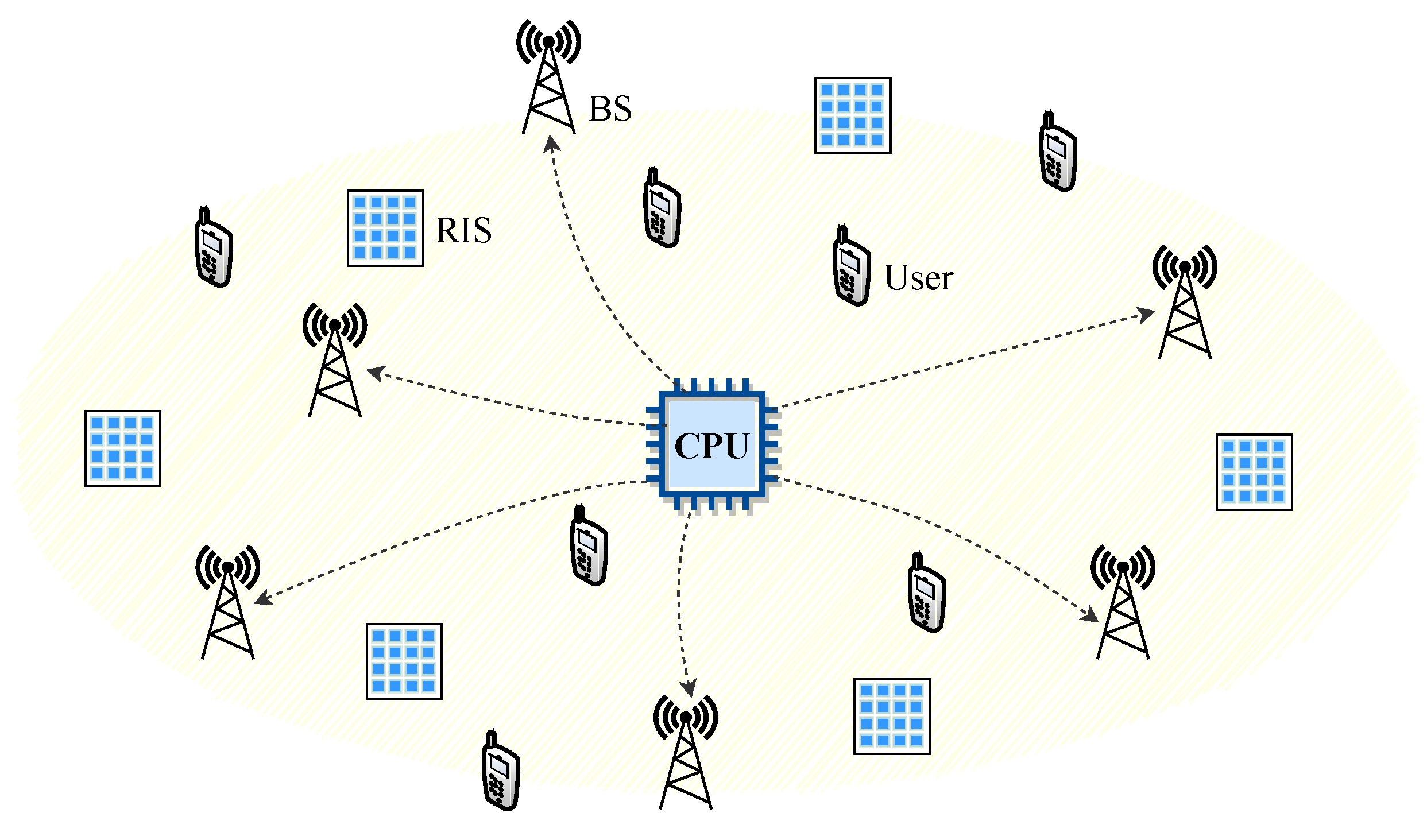
It is entirely conceivable that RIS integration into a CF network, which we are calling an RIS-CF network, would capture all of the key benefits of both techniques, as shown in Figure 1. In such a network, the BSs are connected to the central processing unit (CPU) via error-free forward links, and all BSs cooperate fully under the control of the CPU to serve all users with RIS assistance. Different from the large-scale phased array antennas realized by phase shifters in the CF system, RISs eliminate the need for complex digital phase shifter circuits, significantly reducing energy consumption and signal processing complexity [10]. RISs provide a low-cost way to increase network capacity and achieve broader coverage. Therefore, compared to the traditional CF systems, an RIS-CF system only needs lower power consumption to achieve the same level of quality of service (QoS). This reduction in power consumption is a key advantage that sets the RIS-CF system apart from traditional CF networks. Furthermore, the integration of RIS technology into CF networks offers a new dimension for enhancing network performance.
1.1. Related Works
An RIS’s unique capabilities allow for the low-cost reconfiguration of the propagation environment, capitalizing on multipath effects to optimize spatial resources and enhance wireless network performance. RIS-aided communications have attracted much attention in various applications. Current research on RIS has primarily centered on passive or joint beam-forming design [11,12,13]. Additionally, there have also been works focusing on the deployment of the RIS [14,15,16], physical layer security [17,18,19], RIS-assisted UAV communications [20,21,22], wireless power transfer [23,24,25], and so on. Research on RIS is currently focused on the latest advancements, including the emerging paradigm of stacked intelligent metasurface (SIM) [26] and the innovative idea of a space-time coded RIS [27,28].
By leveraging the programmable nature of RIS elements, the incident wavefronts can be precisely shaped to enhance the CF network. Currently, several researchers are attempting to characterize the performance of RIS-CF networks. References [29,30] considered sum rate maximization and energy efficiency maximization in RIS-CF networks. In detail, the authors in [29] jointly designed a precoding at the BSs and RISs in a CF system. In [30], the authors proposed a hybrid beam-forming strategy that combines digital beam-forming at BSs with analog beam-forming at the RIS. RIS-CF networks provide a cost-effective way to further boost the performance of traditional communication networks. In [31], the authors considered the RIS–user association problem in a RIS-aided system, where it was limited to the case with a single BS serving a single user and there is no coordination between BSs. In contrast to [31], we consider CF networks in this paper where users are served by multiple selected BSs. In [32], the authors investigated the optimization of BS–user associations in RIS-CF networks, aiming to maximize the minimum SINR across all users, thus enhancing the overall network performance, and proposed a two-step fractional linearization algorithm to optimally solve this problem. However, in the solution process, the power of BSs defaults to 1, and the influence of power allocation on the network performance is not considered. In contrast, in this paper, we consider the joint optimization of power and BS selections, which can improve system performance to a greater extent. A comparison of the related works is summarized in Table 1.
1.2. Our Contributions
To fully explore the benefits of the RIS-CF network, we aim to optimize the BS transmit power and BS selections for weighted sum-SINR maximization. We present the main contributions of this paper as follows.
- Based on the considered RIS-CF network and the reflection of the signal by RISs, we derive a closed-form expression of the SINR received by the user. Then, we propose a problem of weighted sum-SINR maximization, aiming to jointly optimize the transmit power of the BSs and the BS selections.
- We present a comprehensive solution to the formulated non-convex optimization problem: we first decompose the problem into two subproblems, each of which is a sum-of-ratios problem. To address this issue, we introduce a two-layer iterative algorithm to disassemble the fraction form. For the nonlinear term after fractional programming transform, we employ the reformulation–linearization method to transform the problem into a mixed-integer linear programming (MILP) problem. This approach will offer valuable insights into challenges, such as fractional programming, involving integer variables.
- The simulation results indicate that the RIS-CF network has a better performance compared to benchmark schemes including the conventional networks and no-RIS cases. The impact of the BS transmit power budget and the number of RIS-reflecting elements on the performance are also shown numerically.
1.3. Organization and Notations
Organization: The rest of the paper is organized as follows. The system model of the proposed RIS-CF network and corresponding weighted sum-SINR maximization problem formulation are discussed in Section 2. A two-layer iterative algorithm is proposed in Section 3 to solve the nonconvex problem. Section 4 provides numerical results to validate the proposed schemes. Finally, Section 5 summarizes the conclusions.
Notations: Bold symbols in capital letters and small letters denote matrices and vectors, respectively. The conjugate transpose of a matrix is denoted as . denotes the set of complex vectors of length n. For a complex number s, and denote its amplitude and phase, respectively, and means that it is a circularly symmetric complex Gaussian (CSCG) random variable with mean and variance . For a vector , denotes an diagonal matrix whose entries are the elements of . denotes the expected value of random variables. denotes an identity matrix. j denotes the imaginary unit, i.e., . denotes the Landau’s symbol to describe the order of convergence as well as complexity. In addition, the major variable definitions in Section 2 are summarized in Table 2.
2. System Model and Problem Formulation
In this section, we present the system model for a general RIS-aided downlink CF communication network. Subsequently, we formulate the joint transmit power and BS selection problem.
2.1. System Model
We consider a downlink multi-RIS-aided multi-user system consisting of N single-antenna users, each of which would benefit from the collaboration of M single-antenna BSs and N RISs, as illustrated in Figure 2. Each RIS r equipped with elements passively reflects the signals from BSs to assist a dedicated user n, such that the system performance can be enhanced. For simplicity, the sets of users/RISs and BSs are, respectively, denoted by and .
In such a system, we assume that a CPU exists for network central processing, and carries out transmission scheduling according to the network information. To ensure accurate channel state information (CSI) at the CPU, various channel acquisition techniques are employed [35,36,37].
The RIS comprises numerous cost-effective passive reflecting elements, each of which can be individually adjusted to manipulate the phase of incident electromagnetic signals using a programmable PIN diode. Thus, RISs can enable signals to be transmitted simultaneously over two links, i.e., direct and reflected links, resulting in more diverse transmissions. As shown in Figure 2, the RISs receive the signals sent by the BSs, and then reflect these signals to the users. To simplify the problem, we assume that the reflection amplitude of each RIS element is maximized at 1 [38]. Additionally, we assume that the signal is reflected ideally without any hardware defects. The phase shift of the l-th RIS element of the RIS r is denoted as and belongs to the interval , while represents the frequency response of RIS r and is defined as a diagonal matrix with diagonal elements .
The channel between BS m and user n in the direct link is denoted as . The fading channels and are, respectively, the channel between the single-antenna BS b and RIS r, and between RIS r and the single-antenna user n. Under the hypothesis of independent Rayleigh fading channels, we have , and . The average power gains and depend on the distances between the BSs, RISs and users.
Moreover, we assume that, if RIS associates with user n, it adjusts its phase shift so that the reflected link, via itself, is aligned with the corresponding direct link of user n. To streamline the practical design of BS selections, we introduce binary variables to represent whether BS m is selected by user n () or not (). We assume that each BS m serves at most one user, while each user can be served by multiple BSs. Additionally, we ensure that there is at least one BS in selected by each user n to provide service coverage. Thus, we have
For coherent joint transmission, we assume, in this paper, the synchronization of all BSs associated with user n, such that user n could receive the exact same symbols from those BSs. Specifically, we denote the received symbol of each user n served by BS m as , where and represent the transmission by each user n and the precoding matrix, respectively. The power of is normalized, i.e., .
It is assumed, in this paper, that intended signals with predetermined phase shifts are reflected by each RIS r purposefully for its associated user n, while the unintended signals are scattered at random. Thus, each user n receives the desired signal from its associated RIS n as well as that scattered by other non-associated RISs [31]. To account for the significant double path loss in the RIS-aided cascaded channel, we exclude any signals that are reflected or scattered more than once by the RIS. The channels from BSs to user n consist of direct links from BSs as well as reflected and scattered links via RISs. Since user n is served by multiple BSs simultaneously, each user n could receive the effective signal composed of the aggregated signals originating from its selected BSs. Thus, the desired signal at user n’s receiver can be expressed as
where .
If BS m sends information signals to user n in the downlink communication, is set to 1. In other words, we can consider the BSs selected by user n as a single multi-antenna BS that employs precoding weights ’s. Consequently, each reflecting element on RIS n adjusts its reflection phase to align the cascaded BS-RIS-user channel with the direct BS-user channel [6]. To achieve this, the l-th phase shift of RIS n needs to be configured as . Thus, in (3) can be rewritten as
Meanwhile, regardless of the desired signal from its own selected BSs, each user n would also receive both the direct interference transmitted by other BSs and the interference reflected by RISs. Thus, each user n would receive the following total interference:
In light of (3) and (5), we could further obtain the average SINR of each user n as
where is the Gaussian noise power. To make the analysis tractable and obtain more insights, we can rewrite (6) to obtain a lower bound on it as follows:
where the inequality is valid as the function is convex in x for , which is derived from Jensen’s inequality.
2.2. Problem Formulation
In this paper, we assume that any group of BSs use the maximum ratio transmission (MRT) [39] to transmit signals to their served user. Then, we can write the precoded weight as
where denotes the transmit power of the BS m to user n. Substituting (3), (5) and (8) to (6), we can obtain the average SINR received by user n as
where , + and . is the average path gain between BS m and user n via RIS r. The derivation process can be referred to in Appendix A of [32], which will not be repeated here for brevity.
According to the above, our objective is to optimize the transmit powers of the BSs and the BS selections to achieve the maximum weighted sum SINR for all users. Denote as the weighting factor to control the scheduling priority of user n and a larger value of signifies a higher priority for information transmission to user n. Based on (9), the weighted sum SINR received by users can be expressed as
Accordingly, we can formulate the optimization problem as
where represents the available transmit power budget of each BS. The BS’s transmit power and BS selections are denoted by and , respectively.
The weighted sum-SINR maximization problem (P0) is a complex task that involves optimizing a nonlinear sum-of-ratios function [40], which involves maximizing a sum of several fractional functions. This non-convex optimization problem is notoriously difficult to solve optimally. Furthermore, the problem requires the joint optimization of the BS transmit power and BS selection, where the latter aspect involves binary/integer variables, i.e., . So, we decompose it into following two subproblems to solve this problem with low complexity.
- BS Transmit Power Subproblem: Given the fixed BS selections , we focus on optimizing the transmit power of each BS, while ensuring it falls within the allocated budget . Then, the BS power problem can be formulated by
- BS Selection Subproblem: Similarly, the BS selection problem with fixed BS transmit power can be written by
3. Proposed Optimization Algorithm
In this section, we develop an algorithm to solve the above weighted sum-SINR maximization problem (P0) via optimally solving the BS transmit power subproblem and BS selection subproblem in an iterative manner.
3.1. BS Transmit Power Allocation
For notational simplicity, we represent the objective function of problem (P1) as
namely, we use and to denote the numerator and denominator of , respectively.
3.1.1. Fractional Programming Transform
Problem (P1) is a sum-of-ratios problem that can be equivalently re-written as follows:
Theorem 1.
If (, ) is the solution of the problem (23), then there exists such that is a solution of the following parameterized problem with parameters :
And also satisfies the following conditions when :
Proof of Theorem 1.
See ([40], Lemma 2.1). □
From Theorem 1, we learn that, when , the parametric problem and the sum-of-ratios maximization problem (P1) have the same optimal solution. Here, represents the optimal parameter values that satisfy the conditions (28) and (29) together with solution to problem .
3.1.2. Two-Layer Approach for Solving Problem (P1)
According to Theorem 1, the problem (P1) can be solved via a two-layer iterative approach. We tackle the parametric problem for a given pair in the inner layer. In the outer layer, we optimize to ensure that , together with the corresponding inner-layer solution , satisfy the conditions (28) and (29).
It is straightforward to verify that, when , the inner-layer problem is a linear program (LP) due to the linear nature of the objective function and constraints. This analytical structure enables us to derive the optimal value in a straightforward manner. To proceed, we initially define , and as follows:
Then, (26) can be expressed as
From (33), we can see that if ( denotes the optimal value of ()), otherwise .
After solving the problem () with given , we employ the modified Newton method [40] to update in the outer layer, which guarantees the convergence to (i.e., meets the conditions (28) and (29)). To begin with, we define some functions for conciseness as follows:
According to ([40], Theorem 3.1), the optimal is unique and can be obtained by solving the non-linear equations: . The modified Newton method can be applied to update to meet these equations. Specifically, the point-wise updating equations of and are
where i is the iteration index and is the step size at iteration i. A discussion on choosing the step size can be found in [40,41] and is thus omitted here. We summarize the main procedures of solving problem (P1) in Algorithm 1.
| Algorithm 1 Two-Layer Iterative Algorithm for Problem (P1) |
|
3.2. BS Selection Design
In this subsection, we develop an approach based on the reformulation–linearization technique to tackle the BS selection problem (P2). The objective function of problem (P2) also follows the sum-of-ratios format. Therefore, similar to the algorithm design for (P1), problem (P2) can be effectively solved using a two-layer iterative approach. The inner layer of this approach involves solving the parameterized problem for given auxiliary parameters , which is expressed as
The outer layer is similar to that of Algorithm 1, i.e., update , via the modified Newton method, (36) and (37). Due to the similarity, we left the detailed implementation of the outer layer in Algorithm 2 and focus on the discussion of solving the inner-layer problem (38).
| Algorithm 2 Two-Layer Iterative Algorithm for Problem (P2) |
|
It is noted that (38) is still an integer linear fractional programming (ILFP) problem with respect to because of the fractional component in the objective function. To proceed, we utilize the reformulation–linearization technique [42] to recast the ILFP problem into an equivalent MILP problem. This transformation enables us to optimize the problem efficiently using standard MILP solvers.
The reformulation–linearization approach consists of two main stages. In the initial stage, we aim to reframe the fractional component in the objective function (38) into an equivalent bilinear term. To achieve this, we introduce supplementary continuous variables and impose equality constraints. Subsequently, in the second stage, we aim to linearize the bilinear term appearing in both the objective function and constraints. The specific steps involved in this transformation are outlined below.
Reformulation: To reformulate the problem, we introduce a new variable defined as
It is important to note that this variable is positive. By substituting (39) into the objective function (38), we can successfully reformulate the problem into the following equivalent form:
where the equality constraint (42) is derived from (39) to define the variable . This reformulation allows us to manipulate the problem in a more tractable manner, paving the way for further optimization techniques. It is worth mentioning that the binary variables remain unchanged in the previous step, leading to a new bilinear term emerging in the objective function (40) as a result of the reformulation. This bilinear term, which involves the multiplication of a binary variable and a continuous variable, necessitates the introduction of additional auxiliary variables and constraints for accurate linearization.
Linearization: To linearize the bilinear term , we introduce a set of auxiliary variables . Subsequently, the problem (40) can be reformulated as an equivalent expression:
To address the bilinear constraint (46) in problem (43), we can utilize the binary nature of to transform it. Specifically, the constraint can be equivalently represented as the following set of linear constraints:
Here, is a large enough constant. Constraint (49) implies that, if , then ; constraints (48) and (50) enforce that, if , then . Therefore, constraints (48)–(50) serve as linearization constraints for and the equivalence holds here as long as .
By linearizing (46) into (48)–(50), we can finally reformulate problem (P2) into a MILP format that can be solved efficiently as follows:
The application of the reformulation–linearization methods described above reveals the mapping between the solutions of (38) and (51). It is worth noting that the transformed MILP problem () maintains the same optimal as the original problem (P2). This is because the reformulation–linearization process involves only variable substitution and exact linearization. This ensures that problem () can be effectively solved using MILP solvers like CPLEX or Gurobi. Consequently, we can employ a two-layer iterative algorithm to solve problem (P2). The complete algorithm is outlined in Algorithm 2.
3.3. Overall Algorithm Description
In this subsection, we describe the whole algorithm that solves the weighted sum-SINR maximization problem (P0) iteratively. The BS transmit power is first solved by Algorithm 1 with fixed BS selections. Based on the obtained BS power, the BS selection is optimized by Algorithm 2. If the objective function values of two consecutive iterations differ by less than a predefined threshold , i.e., (F represents the value of objective function), we consider that the entire algorithm has converged. In light of the above description, the main procedures of the overall algorithm are outlined in Algorithm 3.
| Algorithm 3 The Whole Algorithm |
|
Furthermore, we analyze the convergence of the whole algorithm. By performing Algorithm 1, a better power allocation is achieved with a fixed BS selection in the i-th iteration. Hence, we have
Similarly, given the power allocation , by Algorithm 2, the BS selection is designed to maximize the weighted sum-SINR. Thus, we can obtain
Based on (60) and (61), we obtain
The analysis presented above demonstrates that the objective value of the original problem (P0) consistently exhibits non-decreasing behavior after each iteration. Consequently, the convergence of the algorithm is guaranteed. The non-decreasing behavior of the objective value suggests that the algorithm is effectively moving towards a better solution with each iteration, ultimately converging to a satisfactory solution. This conclusion is further supported by the theoretical foundations of the algorithm, which ensure its convergence to a locally optimal solution in a finite number of iterations.
4. Numerical Results
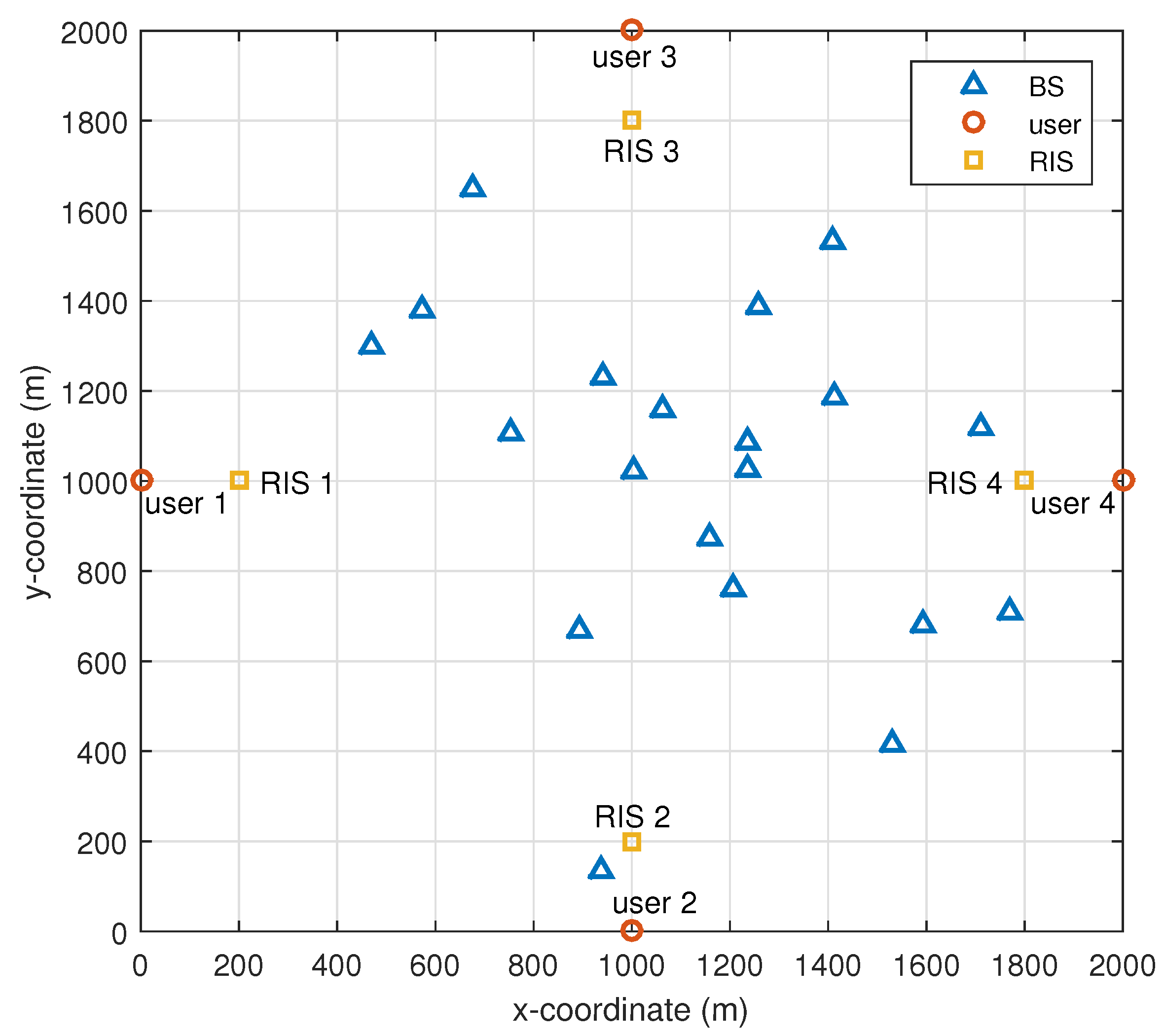
In this section, we evaluate the performance of our proposed algorithm. For our simulations, we utilize the urban macro (UMa) path loss model as specified in the 3GPP technical standard. We set RISs/users, BSs as shown in Figure 3, where BSs are distributed in a square area around users with a side length of 2 km and each RIS is deployed 200 m away from its assisted user. We assume that all BSs and users are equipped with an omnidirectional antenna. Unless otherwise specified, the setting of simulation parameters is outlined in Table 3. For comparison, we consider several benchmark schemes as follows: (1) CF network without RISs, (2) one nearest selection with RISs, and (3) one nearest selection without RISs.
4.1. Comparison with Benchmarks
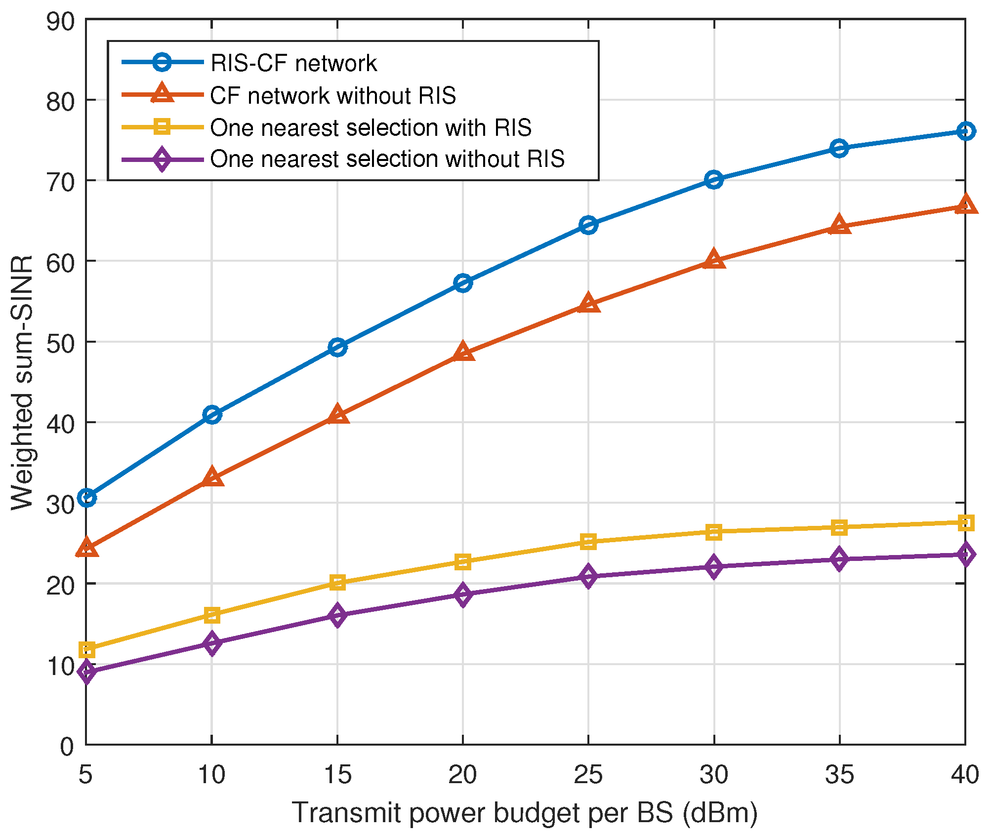
Figure 4 shows the weighted sum-SINR of the RIS-CF system versus the transmit power budget per BS. It is evident that the weighted sum-SINR of all evaluated schemes improves significantly as the transmit power budget increases. Moreover, it is observed that the weighted sum-SINR performance of the CF network surpasses that with the nearest selection schemes by a considerable margin, regardless of whether RISs are employed or not. This is because the CF network has many distributed BSs compared to that with the nearest selection scheme, which provides a higher degree of macro-diversity for communication. It is evident that the performance of both the RIS-CF network and that with the nearest selection with RISs surpasses that of the case without RISs. This improvement is attributed to the fact that signals are transmitted via more propagation paths, i.e., the additional reflected links, indicating that RISs can more efficiently utilize spatial resources. Notably, our proposed RIS-CF network exhibits the best weighted sum-SINR performance among all the evaluated schemes.
4.2. Impact of RIS-Reflecting Elements
To better understand the influence of RISs on the performance of the CF system, we conducted experiments with various numbers of reflecting elements per RIS. Figure 5 clearly demonstrates the weighted sum-SINR with and without BS power allocation. In the absence of power allocation, the transmit power per BS was fixed at 40 dBm. This comparison offers a valuable insight into how our proposed algorithm compares to the benchmark scheme as the number of reflecting elements L varies. It can be observed that, as the number of reflecting elements L increases, the weighted sum-SINR also rises. As expected, all methods that incorporate RISs outperform their counterparts without RISs () in terms of performance. Additionally, the weighted sum-SINR of the RIS-CF network significantly surpasses that with the one nearest selection scheme due to the optimized BS selections. It is worth noting that the weighted sum-SINR performance of the evaluated schemes with power allocation is superior to those without power allocation. However, we can see that, compared with the schemes without BS power allocation, BS power allocation brings more gains to the one nearest selection benchmark than the schemes with optimized BS selections, which shows that SINR balancing is more flexible with BS power allocation.
5. Conclusions
In this study, we conducted an analysis of an RIS-CF system that involves multiple BSs collaborating with multiple RISs to serve distinct users. Our main objective was to maximize the weighted sum-SINR by optimizing both the BS transmit power and BS selections. This problem posed a non-convex sum-of-ratios challenge, which we addressed by decomposing it into two subproblems to solve separately and then optimizing the two variables alternately. In the process of solving this problem, a two-layer iterative algorithm is proposed to transform the non-convex problem into an MILP problem. The numerical results clearly demonstrate the benefits of BS power allocation for both the proposed scheme and the benchmark schemes compared. Furthermore, when the total transmit power of BSs remains unchanged, the RIS-CF system outperforms traditional benchmarking schemes. It is also revealed that a user’s SINR is significantly affected by BS selections, especially in the absence of BS power allocation. This finding highlights the importance of carefully managing BS selections in RIS-CF systems to achieve a better performance.
Furthermore, the work of this paper can also be extended to other possible directions in the future. For example, more general network settings could be considered, such as multi-antenna BSs and users, where the optimization problem becomes more complex and challenging. Additionally, there are many other approaches to selecting BSs in a CF network, which is also worth investigating for comparative study. In addition, this paper considered weighted sum-SINR maximization, while other performance metrics, such as energy efficiency, can also be explored as optimization objectives.
Author Contributions
Conceptualization, Q.B.; methodology, Q.B.; validation, Q.B., Y.Z.; investigation, Q.B.; writing—original draft preparation, Q.B.; writing—review and editing, Q.B., Y.Z.; supervision, Y.L.; project administration, Y.H.; funding acquisition, Y.H. All authors have read and agreed to the published version of the manuscript.
Funding
This work was supported by the National Key R&D Program of China (Project Number: 2022YFB2902100).
Data Availability Statement
Data supporting this study are included within the article.
Conflicts of Interest
All authors were employed by the company China Telecom Research Institute. They declare that the research was conducted in the absence of any commercial or financial relationships that could be construed as a potential conflict of interest.
References
- Yadav, A.; Dobre, O.A. All Technologies Work together for Good: A Glance at Future Mobile Networks. IEEE Wirel. Commun. 2018, 25, 10–16. [Google Scholar] [CrossRef]
- Teng, Y.; Liu, M.; Yu, F.R.; Leung, V.C.M.; Song, M.; Zhang, Y. Resource Allocation for Ultra-Dense Networks: A Survey, Some Research Issues and Challenges. IEEE Commun. Surv. Tutor. 2019, 21, 2134–2168. [Google Scholar] [CrossRef]
- Nguyen, H.V.; Nguyen, V.D.; Dobre, O.A.; Sharma, S.K.; Chatzinotas, S.; Ottersten, B.; Shin, O.S. On the Spectral and Energy Efficiencies of Full-Duplex Cell-Free Massive MIMO. IEEE J. Sel. Areas Commun. 2020, 38, 1698–1718. [Google Scholar] [CrossRef]
- Ngo, H.Q.; Ashikhmin, A.; Yang, H.; Larsson, E.G.; Marzetta, T.L. Cell-Free Massive MIMO Versus Small Cells. IEEE Trans. Wirel. Commun. 2017, 16, 1834–1850. [Google Scholar] [CrossRef]
- Ngo, H.Q.; Tran, L.N.; Duong, T.Q.; Matthaiou, M.; Larsson, E.G. On the Total Energy Efficiency of Cell-Free Massive MIMO. IEEE Trans. Green Commun. Netw. 2018, 2, 25–39. [Google Scholar] [CrossRef]
- Wu, Q.; Zhang, R. Intelligent Reflecting Surface Enhanced Wireless Network via Joint Active and Passive Beamforming. IEEE Trans. Wirel. Commun. 2019, 18, 5394–5409. [Google Scholar] [CrossRef]
- Di Renzo, M.; Debbah, M.; Phan-Huy, D.T.; Zappone, A.; Alouini, M.S.; Yuen, C.; Sciancalepore, V.; Alexandropoulos, G.C.; Hoydis, J.; Gacanin, H.; et al. Smart radio environments empowered by reconfigurable AI meta-surfaces: An idea whose time has come. EURASIP J. Wirel. Commun. Netw. 2019, 2019, 129. [Google Scholar] [CrossRef]
- Hong, I.P. Reviews Based on the Reconfigurable Intelligent Surface Technical Issues. Electronics 2023, 12, 4489. [Google Scholar] [CrossRef]
- Hu, J.; Zhang, H.; Di, B.; Li, L.; Bian, K.; Song, L.; Li, Y.; Han, Z.; Poor, H.V. Reconfigurable Intelligent Surface Based RF Sensing: Design, Optimization, and Implementation. IEEE J. Sel. Areas Commun. 2020, 38, 2700–2716. [Google Scholar] [CrossRef]
- Shlezinger, N.; Dicker, O.; Eldar, Y.C.; Yoo, I.; Imani, M.F.; Smith, D.R. Dynamic Metasurface Antennas for Uplink Massive MIMO Systems. IEEE Trans. Commun. 2019, 67, 6829–6843. [Google Scholar] [CrossRef]
- Wu, Q.; Zhang, R. Beamforming Optimization for Wireless Network Aided by Intelligent Reflecting Surface with Discrete Phase Shifts. IEEE Trans. Commun. 2020, 68, 1838–1851. [Google Scholar] [CrossRef]
- Zhao, M.M.; Wu, Q.; Zhao, M.J.; Zhang, R. Intelligent Reflecting Surface Enhanced Wireless Networks: Two-Timescale Beamforming Optimization. IEEE Trans. Wirel. Commun. 2021, 20, 2–17. [Google Scholar] [CrossRef]
- Ye, C.; Jiang, H.; Luo, Z.; Deng, L. Robust Beamforming Design for IRS-Assisted Downlink Multi-User MISO-URLLC in an IIoT Scenario. Electronics 2023, 12, 1696. [Google Scholar] [CrossRef]
- Zhang, S.; Zhang, R. Intelligent Reflecting Surface Aided Multi-User Communication: Capacity Region and Deployment Strategy. IEEE Trans. Commun. 2021, 69, 5790–5806. [Google Scholar] [CrossRef]
- Liu, X.; Liu, Y.; Chen, Y.; Poor, H.V. RIS Enhanced Massive Non-Orthogonal Multiple Access Networks: Deployment and Passive Beamforming Design. IEEE J. Sel. Areas Commun. 2021, 39, 1057–1071. [Google Scholar] [CrossRef]
- Bie, Q.; Liu, Y.; Wang, Y.; Zhao, X.; Zhang, X.Y. Deployment Optimization of Reconfigurable Intelligent Surface for Relay Systems. IEEE Trans. Green Commun. Netw. 2022, 6, 221–233. [Google Scholar] [CrossRef]
- Chen, J.; Liang, Y.C.; Pei, Y.; Guo, H. Intelligent Reflecting Surface: A Programmable Wireless Environment for Physical Layer Security. IEEE Access 2019, 7, 82599–82612. [Google Scholar] [CrossRef]
- Guan, X.; Wu, Q.; Zhang, R. Intelligent Reflecting Surface Assisted Secrecy Communication: Is Artificial Noise Helpful or Not? IEEE Wirel. Commun. Lett. 2020, 9, 778–782. [Google Scholar] [CrossRef]
- Liu, Z.; Wang, J.; Jiang, H.; Wang, J.; Li, X.; Xie, W. Physical Layer Security Performance Analysis of IRS-Aided Cognitive Radio Networks. Electronics 2023, 12, 2615. [Google Scholar] [CrossRef]
- Qian, P.; Zhang, Y.; Yan, X.; Chen, Y.; Sun, Y. A Robust Scheme for RIS-Assisted UAV Secure Communication in IoT. Electronics 2023, 12, 2507. [Google Scholar] [CrossRef]
- Zou, C.; Li, C.; Li, Y.; Yan, X. RIS-Assisted Robust Beamforming for UAV Anti-Jamming and Eavesdropping Communications: A Deep Reinforcement Learning Approach. Electronics 2023, 12, 4490. [Google Scholar] [CrossRef]
- Liu, Z.; Yang, M.; Cui, J.; Xiao, Y.; Zhang, X. Performance and Capacity Optimization for High Speed Railway Communications Using UAV-IRS Assisted Massive MIMO System. Electronics 2023, 12, 2547. [Google Scholar] [CrossRef]
- Wu, Q.; Zhang, R. Joint Active and Passive Beamforming Optimization for Intelligent Reflecting Surface Assisted SWIPT under QoS Constraints. IEEE J. Sel. Areas Commun. 2020, 38, 1735–1748. [Google Scholar] [CrossRef]
- Pan, C.; Ren, H.; Wang, K.; Elkashlan, M.; Nallanathan, A.; Wang, J.; Hanzo, L. Intelligent Reflecting Surface Aided MIMO Broadcasting for Simultaneous Wireless Information and Power Transfer. IEEE J. Sel. Areas Commun. 2020, 38, 1719–1734. [Google Scholar] [CrossRef]
- Deng, Z.; Pan, Y. Optimal Beamforming for IRS-Assisted SWIPT System with an Energy-Harvesting Eavesdropper. Electronics 2021, 10, 2536. [Google Scholar] [CrossRef]
- An, J.; Di Renzo, M.; Debbah, M.; Poor, H.V.; Yuen, C. Stacked intelligent metasurfaces for multiuser downlink beamforming in the wave domain. arXiv 2023, arXiv:2309.02687. [Google Scholar]
- Verde, F.; Darsena, D.; Galdi, V. Rapidly time-varying reconfigurable intelligent surfaces for downlink multiuser transmissions. IEEE Trans. Commun. 2024. [Google Scholar] [CrossRef]
- Mizmizi, M.; Tagliaferri, D.; Spagnolini, U. Wireless communications with space-time modulated metasurfaces. arXiv 2023, arXiv:2302.08310. [Google Scholar] [CrossRef]
- Zhang, Z.; Dai, L. A Joint Precoding Framework for Wideband Reconfigurable Intelligent Surface-Aided Cell-Free Network. IEEE Trans. Signal Process. 2021, 69, 4085–4101. [Google Scholar] [CrossRef]
- Zhang, Y.; Di, B.; Zhang, H.; Lin, J.; Xu, C.; Zhang, D.; Li, Y.; Song, L. Beyond Cell-Free MIMO: Energy Efficient Reconfigurable Intelligent Surface Aided Cell-Free MIMO Communications. IEEE Trans. Cogn. Commun. Netw. 2021, 7, 412–426. [Google Scholar] [CrossRef]
- Mei, W.; Zhang, R. Performance Analysis and User Association Optimization for Wireless Network Aided by Multiple Intelligent Reflecting Surfaces. IEEE Trans. Commun. 2021, 69, 6296–6312. [Google Scholar] [CrossRef]
- Bie, Q.; Liang, Z.; Liu, Y.; Wu, Q.; Zhao, X.; Zhang, X.Y. User Association for Reconfigurable Intelligent Surfaces Aided Cell-Free Networks. IEEE Trans. Veh. Technol. 2023, 72, 14456–14467. [Google Scholar] [CrossRef]
- Sangeetha, S.; Logeshwaran, J.; Faheem, M.; Kannadasan, R.; Sundararaju, S.; Vijayaraja, L. Smart performance optimization of energy-aware scheduling model for resource sharing in 5G green communication systems. J. Eng. 2024, 2024, e12358. [Google Scholar] [CrossRef]
- Faheem, M.; Kuusniemi, H.; Eltahawy, B.; Bhutta, M.S.; Raza, B. A lightweight smart contracts framework for blockchain-based secure communication in smart grid applications. IET Gener. Transm. Distrib. 2024, 18, 625–638. [Google Scholar] [CrossRef]
- Chen, J.; Liang, Y.C.; Cheng, H.V.; Yu, W. Channel Estimation for Reconfigurable Intelligent Surface Aided Multi-User mmWave MIMO Systems. IEEE Trans. Wirel. Commun. 2023, 22, 6853–6869. [Google Scholar] [CrossRef]
- Mishra, D.; Johansson, H. Channel Estimation and Low-complexity Beamforming Design for Passive Intelligent Surface Assisted MISO Wireless Energy Transfer. In Proceedings of the 2019 IEEE International Conference on Acoustics, Speech and Signal Processing (ICASSP), Brighton, UK, 12–17 May 2019; pp. 4659–4663. [Google Scholar] [CrossRef]
- Liu, H.; Yuan, X.; Zhang, Y.J.A. Matrix-Calibration-Based Cascaded Channel Estimation for Reconfigurable Intelligent Surface Assisted Multiuser MIMO. IEEE J. Sel. Areas Commun. 2020, 38, 2621–2636. [Google Scholar] [CrossRef]
- Kaina, N.; Dupré, M.; Lerosey, G. Shaping complex microwave fields in reverberating media with binary tunable metasurfaces. Sci. Rep. 2014, 4, 6693. [Google Scholar] [CrossRef] [PubMed]
- Tse, D.; Viswanath, P. Fundamentals of Wireless Communication; Cambridge University Press: Cambridge, UK, 2005. [Google Scholar]
- Jong, Y. An Efficient Global Optimization Algorithm for Nonlinear Sum-Of-Ratios Problems. 2012. Available online: https://optimization-online.org/2012/08/3586 (accessed on 7 August 2012).
- Huang, Y.; Liu, Y.; Li, G.Y. Energy Efficiency of Distributed Antenna Systems With Wireless Power Transfer. IEEE J. Sel. Areas Commun. 2019, 37, 89–99. [Google Scholar] [CrossRef]
- Yue, D.; Guillén-Gosálbez, G.; You, F. Global optimization of large-scale mixed-integer linear fractional programming problems: A reformulation-linearization method and process scheduling applications. AICHE J. 2013, 59, 4255–4272. [Google Scholar] [CrossRef]
Figure 1.
The proposed concept of an RIS-CF network.

Figure 2.
The system model of the considered scenario in the RIS-CF network.

Figure 3.
System setup.

Figure 4.
Weighted sum-SINR versus BS transmit power budget.

Figure 5.
Weighted sum-SINR versus RIS-reflecting elements number.


Table 1.
Comparison of some related works.
| Author | Advantage | Limitation |
|---|---|---|
| Zhang et al. [29] | The network capacity can be improved by joint design precoding at BSs and RISs in an RIS-CF network. | A lack of consideration for other performance metrics such as the energy efficiency and BS transmit power. |
| Zhang et al. [30] | The hybrid beam-forming strategy achieves a higher energy efficiency performance than traditional ones. | It ignores the impact of different users’ selections of BSs on the system performance. |
| Mei et al. [31] | It balances the passive beam-forming gains from all IRSs among different BS–user communication links. | It only considers the case where a single BS serves a single user and ignores the coordination between BSs. |
| Bie et al. [32] | It enhances the overall network performance by maximizing the minimum SINR across all users. | A lack of consideration for the influence of power allocation on network performance. |
| Sangeetha et al. [33] | Reduced energy consumption with a high level of resource utilization by considering the specific characteristics of 5G green communication systems. | It may not cope with the optimization of the RIS-CF network performance directly. |
| Faheem et al. [34] | It enables resilient and secure real-time control and monitoring in smart grids. | It may not cope with the optimization of the RIS-CF network performance directly. |
Table 2.
Variable definitions.
| Notation | Description |
|---|---|
| M | Number of BSs |
| N | Number of RISs/users |
| L | Number of RIS-reflecting elements |
| Phase shift of the l-th element of RIS r | |
| Reflection coefficients matrix of RIS r | |
| Direct channel from BS m to user n | |
| Channel from BS m to RIS r | |
| Channel from RIS r to user n | |
| Average power gain of | |
| Average power gain of | |
| Average power gain of | |
| User n’s selection of BS m | |
| Transmitted symbol of user n | |
| Precoding weight used by BS m for user n | |
| Desired signal received by user n | |
| Interference received by user n | |
| Average SINR received at the user n | |
| Lower bound of |
Table 3.
System parameters.
| Parameter | Value |
|---|---|
| Number of BSs, M | 20 |
| Number of RISs/users, N | 4 |
| Number of RIS-reflecting elements, L | 1000 |
| Noise power spectrum density, | dBm/Hz |
| Distance between users and RISs, | 200 m |
| Total transmit power budget of each BS | 40 dBm |
| System bandwidth | 20 MHz |
| Path loss | dB |
| Shadow fading | 8 dB |
| Number of Monte Carlo simulations | 500 |
Disclaimer/Publisher’s Note: The statements, opinions and data contained in all publications are solely those of the individual author(s) and contributor(s) and not of MDPI and/or the editor(s). MDPI and/or the editor(s) disclaim responsibility for any injury to people or property resulting from any ideas, methods, instructions or products referred to in the content. |
© 2024 by the authors. Licensee MDPI, Basel, Switzerland. This article is an open access article distributed under the terms and conditions of the Creative Commons Attribution (CC BY) license (https://creativecommons.org/licenses/by/4.0/).
Share and Cite
MDPI and ACS Style
Bie, Q.; Zhang, Y.; He, Y.; Lin, Y. Joint Base Station Selection and Power Allocation Design for Reconfigurable Intelligent Surface-Aided Cell-Free Networks. Electronics 2024, 13, 1688. https://doi.org/10.3390/electronics13091688
AMA Style
Bie Q, Zhang Y, He Y, Lin Y. Joint Base Station Selection and Power Allocation Design for Reconfigurable Intelligent Surface-Aided Cell-Free Networks. Electronics. 2024; 13(9):1688. https://doi.org/10.3390/electronics13091688
Chicago/Turabian StyleBie, Qingyu, Yuhan Zhang, Yufeng He, and Yilin Lin. 2024. "Joint Base Station Selection and Power Allocation Design for Reconfigurable Intelligent Surface-Aided Cell-Free Networks" Electronics 13, no. 9: 1688. https://doi.org/10.3390/electronics13091688
Note that from the first issue of 2016, this journal uses article numbers instead of page numbers. See further details here.