Article

Characterization of Unit Cells of a Reconfigurable Intelligence Surface Integrated with Sensing Capability at the mmWave Frequency Band

1
Smart Natural Space Research Centre, Kongju National University, Cheonan 31080, Republic of Korea
2
Department of Smart Information Technology Engineering, Kongju National University, Cheonan 31080, Republic of Korea
*
Author to whom correspondence should be addressed.
Electronics 2024, 13(9), 1689; https://doi.org/10.3390/electronics13091689
Submission received: 1 April 2024 / Revised: 24 April 2024 / Accepted: 24 April 2024 / Published: 26 April 2024
(This article belongs to the Special Issue Trends and Prospects in 6G Wireless Communication)

Abstract

:
Integrated sensing and communication (ISAC) is emerging as a main feature for 5G/6G communications. To enhance spectral and energy efficiencies in wireless environments, reconfigurable intelligent surfaces (RISs) will play a significant role in beyond-5G/6G communications. Multi-functional RISs, capable of not only reflecting or transmitting the beam in desired directions but also sensing the signal, wirelessly transferring power to nearby devices, harvesting energy, etc., will be highly beneficial for beyond-5G/6G applications. In this paper, we propose a nearly 2-bit unit cell of RISs integrated with sensing capabilities in the millimeter wave (mmWave) frequency band. To collect a very small fraction of the impinging signals through vias, we employed substrate integrated waveguide (SIW) technology at the bottom of the unit cell and a via. This enabled the sensing of incoming signals, requiring only a small amount of the impinging signal to be collected through SIW. Initially, we utilized Floquet ports and boundary conditions to obtain various parameters of the unit cells. Subsequently, we examined 1 × 3-unit cells, placing them on the waveguide model to obtain the required parameters of the unit cell. By using the waveguide and 1 × 3-unit cell arrays, the sensing amount was also determined.

1. Introduction

The commercial deployment of 5G wireless mobile communications is progressing globally [1,2]. However, the current deployment of 5G wireless mobile communications is exposing the limitations of this technology. Researchers and engineers worldwide are eagerly looking forward to 6G technologies to address these limitations. In [3], the authors initially presented significant achievements and obstacles encountered in the evolution from 1G to 5G. This analysis involved exploring various aspects such as regulation, services, innovations, and other pertinent issues specific to each generation. The authors figured out various requirements of 6G technology that could not be presented using previous mobile communication technology. Cost reduction is a very important task for 6G communications. A detailed vision for 6G connectivity, which aims to reduce costs by 1000 times from a non-technical customer’s perspective, was presented in [4]. The authors emphasized AI-assisted intelligent communication systems. Some technology has the highest priorities in 6G communications, like the optimization and design of AI/ML-driven air interfaces, new frequency bands and new cognitive spectrum sharing methods, the integration of sensing and localizations, low latency and high realizabilities, new network architecture, new privacy, and securities [5]. It is expected that 6G technology will support various applications like virtual reality [6], augmented reality [7], mixed reality [8], brain–computer interfaces [9], indoor localizations [10], connected unmanned aerial vehicles [11], connected autonomous vehicles [12], connected health [13], smart cities [14], integrated sensing and communications [15], etc. A promising candidate in 6G communications is the reconfigurable intelligent surface (RIS) [16]. For 5G wireless mobile applications, a new frequency band called Frequency Range 2 (FR2) has been allocated in the mm-Wave frequency band, ranging between 24.25 GHz and 52.6 GHz [17]. The mm-Wave frequency band can support higher data rates, a crucial factor for some 5G applications. However, a significant challenge with the mmWave frequency band is severe path loss. To tackle this issue, massive multiple-input multiple-output (MIMO) antennas with beam-forming capabilities are being employed [18,19]. Nevertheless, the coverage hole problem in the mm-Wave frequency band remains challenging to solve even with advanced massive MIMO antennas. This coverage hole problem is not only prominent in 5G mobile applications but also poses a fundamental issue for beyond-5G/6G applications. The envisioned 6G applications will not only utilize sub-6 GHz and mm-Wave frequency bands but also sub-terahertz and terahertz frequency bands. To address this fundamental problem, several techniques are being proposed in the literature, and the use of RISs is being considered as one of the possible solutions to overcome the coverage hole problem. The RIS consists of unit cells, and each unit cell can have its impedance tuned by various means. The unit cell of RISs can be tuned by various methods like varactor diodes, PIN diodes, microelectromechanical systems (MEMS), thermal variations, liquid crystals, RF switches, graphene, VO2, etc. In 6G, we expect service that needs both sensing and communication [20,21]. The growing complexity and requirements of modern technological ecosystems, along with the push towards more intelligent and integrated systems, necessitate improved sensing and communication capabilities within the context of 6G communication. A single system that combines wireless communication and radar sensing capabilities is the ISAC. The system uses the same hardware and the same frequency band for its operations. In this work, we propose a nearly 2-bit unit cell of RISs with integrated sensing capabilities. The proposed design will be useful for 6G communications because it integrates two systems into one system, allowing us to use the electromagnetic spectrum more efficiently, and also allowing a reduction in costs and enhanced performance. The integration of sensing capabilities into the communication system enhances the capabilities of many applications like self-driving cars, drones, smart cities, etc.
In the literature, there are a very large number of research papers on RISs available in the theoretical aspect [22,23,24]. However, the hardware for RISs in the literature is still very limited. It is expected that multi-functional RISs will play a significant role in beyond-5G/6G communications. The RISs shall not only reflect the signal in the desired directions but also act as a sensing element. In [25], the authors showed that a simple electronically reconfigurable reflectarray can be used for cost-effective and complexity-reduced location estimation. The concept of the integration of sensing, localizations, and communications with RISs was presented in [26]. In this context, the authors discovered that self-adaptive RISs can only perform better than context-ignorant RISs below a certain noise level. The authors discussed the conditions of self-adaptive RIS, and this could be key technology for 6G communications. Our proposed unit cell could implement the idea proposed in that paper. ISAC shares the same frequency band and the same hardware for its operations. It is expected that ISAC will be a key enabler for 6G communications, and sensing and communications will coexist. ISAC can provide various applications like environmental monitoring, remote sensing, smart homes, sensing as a service, smart manufacturing, vehicle to everything, etc. Communication-assisted sensing and sensing-assisted communication could be very useful for future perceptive networks. ISAC will not only provide a new air interface for the 6G network, but can also be used to combine the physical and cyber worlds [27]. In [28], a sensor-integrated RIS was proposed for optimal 5G communications. The authors verified both sensing and beamforming capabilities in the 28 GHz frequency band. Varactor diodes were used to manipulate the electric and magnetic properties of the surface to obtain a reconfigurable structure. A 1 × 4 unit–unit was designed to verify sensing and beamforming operations. The via wall was used to eliminate the phase distortion of the sensed signal. In [29], the authors proposed a RIS with integrated sensing capabilities. A small portion of the incident wave was collected by arrays of the sensing waveguides. The angle of arrival of the incoming signal was determined from the collected sample signal. The technique of reducing the number of required sensors was also demonstrated in that paper by using the tunable multiplexing capabilities of the metasurface. In [30], the authors proposed a metasurface made of two types of elements, conventional and hybrid. The hybrid element was designed to pass some of the incident signals into the sensing layer. The proposed metasurface was able to produce reconfigurable radiation patterns, and the proposed structure was able to facilitate compress-sensing operations of the incident signals. Thus, without any feedback loops or dedicated links, the response could be adapted, and smart or autonomous operation could be realized. In [31], the authors proposed an RIS with a sensor for mmWave applications. In this method, a small portion of the received signal went through the via, which connected the top metal plane and bottom ground plane. The authors used a Rotman lens and power detector to change the phase of the incident wave to a DC current. Beamforming capabilities were verified through error vector magnitude (EVM) with a commercial mmWave cellphone. A cost-effective and simple RIS structure was realized through a microcontroller unit where an algorithm was provided. Beyond-5G/6G communications will possess wireless sensing capabilities in addition to wireless communication. Wireless sensing aims to precisely and effectively detect, estimate, and derive valuable physical data or characteristics from specific targets through the utilization of radio wave propagation, reflection, diffraction, and scattering [32]. In [33], the authors discussed integrated sensing and communications with RIS. The authors also discussed future directions and applications for ISAC. It is anticipated that ISAC with RISs will be able to provide ultra-reliable, high-accuracy, and wide-coverage communications and sensing functionalities.
In our paper, we have designed a nearly 2-bit operation of an RIS working in the 29 GHz frequency band. A 2-bit unit cell has four states that are 90° apart. However, in practice, the phases of the four states are not exactly 2-bit but are nearer. We have four states in our design, but they are not exactly 90° apart. That is why we called it “nearly 2-bit” in our paper. In [17], the authors presented a 2-bit RIS and a practical path loss model. Our work is an extension of the work presented in [17]. We have introduced a SIW to collect some of the impinging signal in addition to the nearly 2-bit operation. Thus, the direction of arrival (DOA) of the incoming signal can be obtained with the collected signal from the SIW port using appropriate circuits. The proposed design is one of the most promising designs in the area of RIS. We have also designed waveguides, waveguide transition sections, and a 1 × 3-unit cell array. The purpose of designing such an array is to check the unit cell performance without designing a total array. Also, with the waveguide model, the sensing amount can be obtained from the sensing port of the unit cell. It is commonly known that beyond-5G/6G communications will employ the mmWave frequency band. Our proposed design will be useful for 6G communications and beyond. However, the precise frequency spectrum for 6G communications has yet to be defined. As a result, we have attempted to present a novel type of design capable of combining beam steering and sensing. This paper seeks to contribute to this emerging field by providing a comprehensive characterization of the individual unit cells that constitute a sensing-integrated RIS. This type of unit cell has not been proposed earlier. The proposed work advances our understanding of hardware design integrated with sensing operations.

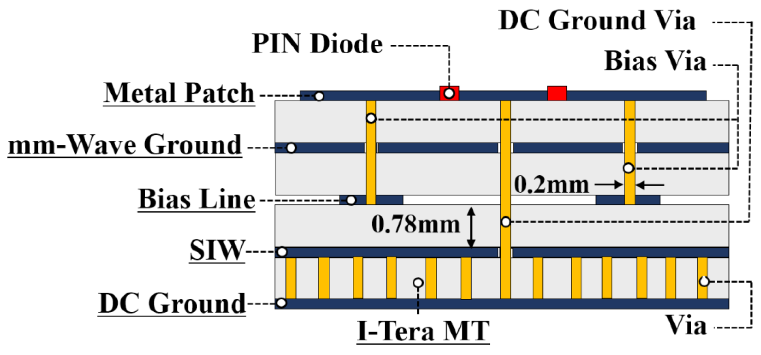
2. Design of the Unit Cell

Figure 1 shows the 3D view of the proposed unit cell. As shown in Figure 1, the unit cell has a total of four layers. An Isola I-TeraMT(R) substrate with a permittivity of 3.45, a loss tangent of 0.0031, and a height of 0.78 mm was used for our proposed unit cell. The size of the unit cell at 29 GHz was 0.48λ0 in terms of wavelength. On the top layer, there was the metallic pattern for the nearly 2-bit operation with two PIN diodes. The top of the second layer was the mmWave ground, and a metallic layer was created at the top of the second layer for mmWave grounding operations. To bias the two PIN diodes, biasing lines are required. There were two PIN diodes used to obtain 2-bit operations. On the top of the third layer, biasing lines were designed. The biasing lines had no significant effect on the overall performance of the unit cell. A SIW structure was conceived for the sensing operations at the bottom of the unit cell.
The SIW structure preserves the properties of conventional metallic waveguides. It can propagate TE modes inside the SIW structure; however, it does not support TM modes inside the structure. In the bottom layer, rows of vias were added to make a SIW structure. Figure 2 shows the top view of the proposed unit cell. The conducting top copper layer was divided into seven parts. The two PIN diodes were connected to three copper parts. There were four parasitic patches, and the sizes of each patch were different so that the overall resonance of the unit cell for different states could be different. This phenomenon helped to keep the magnitude of the reflection coefficients at different frequencies to a minimum for the different states of the unit cell. Using this method, a nearly 2-bit RIS was created. The PIN diodes could be biased by applying voltages, and the control of these diodes was undertaken by employing three vias. The DC ground plane was realized for the PIN diode biasing with the SIW structure. We configured the structure in a manner that eliminated the need for additional DC and RF decoupling circuits. The SIW structure acted as a DC and RF decoupling circuit in our design. As can be observed in Figure 1, bias lines (Layer 3) were utilized to connect one end of the biasing. The other end of the PIN diode, on the other hand, was connected via the SIW structure. Because the waves were confined inside the structure, the SIW structure could only pass DC, and the mm-wave component at the other end of the PIN diode biasing lines was negligible. To simulate the proposed unit cell, the ANSYS High-Frequency Structure Simulator (HFSS) was used.
Figure 3 shows the side view of the unit cell. Each unit cell had a height of 0.78 mm, and the total height of the unit cell was 3.12 mm. As shown in Figure 3, one via, which was located in the middle of the unit cell, connected the top layer and the bottom layer. The function of this via was to provide the biasing of the PIN diode and transfer the mmWave signal to the SIW structure. Another via was there, which connected the bottom of the mmWave ground plane to the top of the SIW structure to provide the required grounding for the collected signal through the SIW. In this design, we defined two ground planes. We designated one ground plane as the mm-Wave ground plane and another as the DC ground plane. The DC ground plane and mmWave ground plane were connected through the SIW structure. Figure 4a shows the DC circuit configuration of our proposed unit cell. As shown in Figure 4a, two PIN diodes were connected back-to-back, and the central via gave DC grounding. The equivalent circuit of the PIN diode is shown in Figure 4b. In our design, Macon MADP-000907-14020x (Solderable AlGaAs Flip Chip PIN) diodes were used.
The typical forward bias resistance of the said diode was 5.2 Ω, and the typical total capacitance in the reverse bias condition was 0.025 pF. When the PIN diode is in the forward bias, it can be represented as a series inductance and resistor. Conversely, in the reverse bias condition, it can be modeled as a parallel resistor and capacitor with an inductor connected in a serial configuration. The dimensions of the proposed unit cell were 5 mm × 5 mm, which was smaller than the free space wavelength in the 29 GHz frequency band, ensuring the avoidance of grating lobes. The electric field distributions of the top patch of the unit cell are depicted in Figure 5a–d for State 1, State 2, State 3, and State 4, respectively. State 1, State 2, State 3, and State 4 are different biasing conditions of the PIN diodes in our design. Figure 6 shows the magnitude of the reflection coefficient for different states. We optimized our design at 29 GHz. At 29 GHz, the magnitudes of the reflection coefficients were −1.0 dB, −0.24 dB, −0.4 dB, and −0.35 dB, respectively, for “State 1”, “State 2”, “State 3”, and “State 4”, respectively. It was noted from these data that the minimum value of the magnitude of the reflection coefficient was within −1.0 dB. The values of the phase of the reflection coefficients at 29 GHz for different states of the unit cell were 25°, −21°, 88°, and −102°, respectively, as shown in Figure 7. From these values, it can be observed that the unit cell gives nearly 2-bit operation in the 29 GHz frequency band.
It is worth noting that the operating frequency range of the unit cell was 28.7 to 29.5 GHz. Nonetheless, within frequency ranges, the phase difference between states is not constant. More PIN diodes can help enhance the consistency of phase differences between the unit cell’s various states [34]. Furthermore, providing a phase offset function improves the consistency of the phase differences between the unit cell states [35]. In our design, we focused on using minimum numbers of PIN diodes to obtain nearly 2-bit operation. The main goal of this work was to provide an innovative idea that could be useful for 6G or beyond 6G communicants. We did not fabricate the structure due to the high cost of fabrication. Although we did not fabricate the unit cell or arrays, we verified the performance of the proposed unit cell in two scenarios. Initially, we verified with the Floquet port model, and after that, we verified our proposed unit cell in the waveguide model. Normally, in the literature, lots of RISs are designed based on 1-bit configurations. However, 1-bit RIS has fewer resolution capabilities. The resolution of the 2-bit RIS is higher than that of the 1-bit RIS. The quantization loss is lower in 2-bit RIS cases than in 1-bit RIS cases, which is another important aspect. The performance of the unit cell in terms of magnitude and phase should be good enough to estimate the DOA of the incoming signal. We placed the unit cell in the waveguide environment to assess its performance in that environment. Nevertheless, transition sections exist in the waveguide environment, which negatively affects the phase responses of the 1 × 3-unit cell. However, the performance of the unit cell in the waveguide environment is not important in real-world applications for estimating the DOA of the incoming signal. It is crucial to consider the unit cell and performances of the array with the Floquet port. Our proposed unit cell can be used to estimate the DOA of the incoming signal because, as Figure 6 and Figure 7 show, the magnitude and phase responses are good with the Floquet port.

3. Design of the Waveguide and Waveguide Transition Section

Before designing the whole RIS array, it is important to characterize the performance of the unit cells. It helps reduce the initial fabrication errors. Thus, before fabricating the whole RIS, we took a 1 × 3-unit cell array, and we wanted to check its performance in the waveguide environment and measure the amount of sensing from the sensing port of the unit cell. To characterize the unit cell and verify its performance with the waveguide, we chose the WR-28 waveguide, which can operate from 26.5 GHz to 40 GHz. The size of our unit cell was 5 mm × 5 mm. However, the size of the aperture of the said waveguide was 7.112 mm × 3.556 mm. Therefore, with this aperture size, it was not possible to fit the single unit cell on the waveguide aperture. Hence, to overcome this problem, we designed rectangular transition sections and we took a 1 × 3-unit cell array for the aperture of the proposed rectangular transition section. To verify the performance of the waveguide with transition sections, we took two waveguides and two transition sections together, as shown in Figure 8. Figure 9 shows the magnitude of the reflection and transmission coefficients with the said configuration of waveguides and the transition sections. It can be observed from Figure 9 that the magnitude of reflection coefficients remained below −23 dB within the 24.5–35 GHz frequency range. At 29 GHz, the magnitudes of transmission and reflection coefficients were −0.011 dB and −25.6 dB, respectively.

4. The 1 × 3-Unit Cell Inside the Waveguide and Its Performance

To check the performances of the unit cells in waveguide environments, we placed 1 × 3-unit cells as shown in Figure 10. It should be mentioned here that a series of vias around the 1 × 3-unit cells were designed so that it could mimic the waveguide characteristics and performances of the 1 × 3-unit without any significant losses. In the waveguide model, all three elements were identical. We put different configurations (State 1, State 2, State 3, and State 4) of the unit cells inside the waveguide and checked their magnitude and phase responses. Figure 11 shows the magnitude of the reflection coefficients obtained using the waveguide. At 29 GHz, the values of the magnitude of the reflection coefficients with the waveguide model were −1.05 dB, −1.3 dB, −0.85 dB, and −2.7 dB for “State 1”, “State 2”, “State 3”, and “State 4”, respectively. Figure 12 shows the phase of the reflection coefficients for different states of the proposed unit cell. It also needs to be mentioned here that a reasonable match of the magnitude of reflection coefficients was obtained in the waveguide model and the Floquet port model of the unit cell of the waveguide. Because of the differences in the waveguide’s length and the Fouquet port’s distance from the proposed unit cell, the phase results for the two scenarios differed. The waves impinged at a 0° angle and at a specific distance from the surface in the Floquet port environment. On the other hand, the waves reached the 1 × 3-unit cell array from different distances and reached the unit cell array at an angle with a transition section. The angle of the incoming signal had an impact on the proposed design. The phase response changed when the incoming signals came from different angles. For this reason, the phase response of the unit cell arrays using the waveguide model changed.

5. Determination of Sensing Amount from the 1 × 3 Unit Cell Array Model

A SIW structure was integrated at the bottom of the unit cell to collect a very small portion of the incoming signal for sensing purposes. Figure 13 shows the electric field distribution inside the SIW structure with the Floquet port. This signal can be sensed by various means, like a Rotman lens with power detectors and a microprocessor unit.
The sense signal can be used to estimate the DOA of the impinging signal on the RIS structure. To measure the amount of sensing in the sensing port, we used a 1 × 3-unit cell array with waveguides and waveguide transition sections. The amount of power coupled to the sensing port was determined. Figure 14 shows the amount of power coupled to the sensing port, and it was −20.7 dB at 29 GHz. The amount of coupling confirms that the diode-driven reflectarray combines with the SIW structure. In our paper, we have not discussed in detail how sensing could be implemented. However, the sensing implementation technique discussed in [31] is applicable to our proposed structure.
Table 1 highlights the uniqueness of our proposed unit cell by comparing it to existing designs with integrated sensing capabilities available in the literature. In our proposed design, we used PIN diodes to achieve 2-bit operation. The utilization of 2-bit operations has the advantage of lowering quantization losses. Using 2-bit operations can thus significantly lower the sidelobe level. Varactor diodes can be employed as well to create designs. In contrast, the varactor complicates the external biasing circuit. The external biasing circuit is simpler than that of a varactor diode since the waves are digitized using a PIN diode. The main difference between a varactor-diode- and a PIN-diode-based RIS is that a varactor-diode-based RIS uses a varactor diode for its switching operations, while a PIN-diode-based RIS uses a PIN diode for its switching operations. The PIN diode has two states, whether it is in the “on” state or the “off” state. Thus, to bias the PIN diode, two voltage levels are required. However, the varactor diode needs a continuous voltage variation or a large number of voltage variations for its operations. Designing an external circuit for RISs with two voltage levels is much simpler and easier than designing an external circuit with continuous voltage variations or a large number of voltage variations. Normally, in the literature, many RISs are designed based on 1-bit configurations. However, 1-bit RISs have fewer resolution capabilities. Furthermore, 2-bit RISs have higher resolution compared to the 1-bit configurations. The proposed design can be modified and tuned more to obtain an exact 2-bit unit cell.

6. Conclusions

In this paper, a novel nearly 2-bit unit cell of RISs integrated with sensing capabilities is proposed to operate at 29 GHz. It is expected that multi-functional RISs are going play a significant role, and the proposed design is promising in the area of multifunctional RISs. We used both the Floquet port and waveguide model to check the performance of the unit cells. Before the fabrication of the whole RIS array, it is essential to verify the performance of the unit cells in a waveguide model. In our proposed unit cell, two PIN diodes were present, and could provide four states. By employing vias and SIW technology, a small impinging signal was collected to sense incoming signals. The sense signal can be used to determine the DOA of the incoming signal. SIW offers a conventional substrate-based approach to realize a metallic waveguide-like structure. Additionally, a series of vias were included in the 1 × 3 unit cell array to acquire phase information. The amount of coupling was also determined with the 1 × 3-unit cell array and waveguide model. A 1 × 3-unit cell is not suitable for actual RIS deployment. We designed a 1 × 3-unit cell array, since we wanted to characterize the RIS unit cell in the waveguide environment. An array of greater sizes can be designed using the proposed unit cell. With the proposed unit cell, we can simply design a 10 × 10 or 20 × 20-unit cell array.

Author Contributions

I.-P.H. conceived this project and contributed to solving the problem, reviewing and editing, and validating the results. B.R. conducted simulations and wrote this paper. S.-S.C. conducted a simulation and drew the figures. All authors have read and agreed to the published version of the manuscript.

Funding

This research was supported in part by the Korea Basic Science Institute (National Research Facilities and Equipment Center), Grant 2022R1A6C101A741, funded by the Ministry of Education, in part by the Basic Science Research Program under Grant 2020R1I1A3057142, and in part by the Priority Research Center Program through the National Research Foundation under Grant 2019R1A6A1A03032988.

Data Availability Statement

The data can be shared up on request.

Conflicts of Interest

The authors declare no conflicts of interest.

References

  1. Shafi, M.; Molisch, A.F.; Smith, P.J.; Haustein, T.; Zhu, P.; De Silva, P.; Tufvesson, F.; Benjebbour, A.; Wunder, G. 5G: A tutorial overview of standards, trials, challenges, deployment, and practice. IEEE J. Sel. Areas Commun. 2017, 6, 1201–1221. [Google Scholar] [CrossRef]
  2. Gupta, A.; Jha, R.K. A survey of 5G network: Architecture and emerging technologies. IEEE Access 2015, 3, 1206–1232. [Google Scholar] [CrossRef]
  3. David, K.; Berndt, H. 6G vision and requirements: Is there any need for beyond 5G? IEEE Veh. Technol. Mag. 2018, 13, 72–80. [Google Scholar] [CrossRef]
  4. Zhang, S.; Xiang, C.; Xu, S. 6G: Connecting everything by 1000 times price reduction. IEEE Open J. Veh. Technol. 2020, 1, 107–115. [Google Scholar] [CrossRef]
  5. Viswanathan, H.; Mogensen, P.E. Communications in the 6G era. IEEE Access 2020, 8, 57063–57074. [Google Scholar] [CrossRef]
  6. Liu, X.; Deng, Y.; Han, C.; Di Renzo, M. Learning-based prediction, rendering and transmission for interactive virtual reality in RIS-assisted terahertz networks. IEEE J. Sel. Areas Commun. 2021, 40, 710–724. [Google Scholar] [CrossRef]
  7. Liao, S.; Wu, J.; Li, J.; Konstantin, K. Information-centric massive IoT-based ubiquitous connected VR/AR in 6G: A proposed caching consensus approach. IEEE Internet Things J. 2020, 8, 5172–5184. [Google Scholar] [CrossRef]
  8. Shin, J.H.; Park, S.J.; Kim, M.A.; Lee, M.J.; Lim, S.C.; Cho, K.W. Development of a digital twin pipeline for interactive scientific simulation and mixed reality visualization. IEEE Access 2023, 11, 100907–100918. [Google Scholar] [CrossRef]
  9. Rana, B.; Shim, J.Y.; Chung, J.Y. An implantable antenna with broadside radiation for a brain–machine interface. IEEE Sens. J. 2019, 19, 9200–9205. [Google Scholar] [CrossRef]
  10. Fan, S.; Wu, Y.; Han, C.; Wang, X. SIABR: A structured intra-attention bidirectional recurrent deep learning method for ultra-accurate terahertz indoor localization. IEEE J. Sel. Areas Commun. 2021, 39, 2226–2240. [Google Scholar] [CrossRef]
  11. Shang, B.; Shafin, R.; Liu, L. UAV swarm-enabled aerial reconfigurable intelligent surface (SARIS). IEEE Wirel. Commun. 2021, 28, 156–163. [Google Scholar] [CrossRef]
  12. Chen, X.; Leng, S.; He, J.; Zhou, L. Deep-learning-based intelligent intervehicle distance control for 6G-enabled cooperative autonomous driving. IEEE Internet Things J. 2021, 8, 15180–15190. [Google Scholar] [CrossRef]
  13. Islam, S.M.R.; Kwak, D.; Kabir, M.H.; Hossain, M.; Kwak, K.-S. The internet of things for health care: A comprehensive survey. IEEE Access 2015, 3, 678–708. [Google Scholar] [CrossRef]
  14. Yang, J.; Kwon, Y.; Kim, D. Regional smart city development focus: The South Korean national strategic smart city program. IEEE Access 2021, 9, 7193–7210. [Google Scholar] [CrossRef]
  15. Cui, Y.; Liu, F.; Jing, X.; Mu, J. Integrating sensing and communications for ubiquitous IoT: Applications, trends, and challenges. IEEE Netw. 2021, 35, 158–167. [Google Scholar] [CrossRef]
  16. Rana, B.; Cho, S.-S.; Hong, I.-P. Review paper on hardware of reconfigurable intelligent surfaces. IEEE Access 2023, 11, 29614–29634. [Google Scholar] [CrossRef]
  17. Jeong, J.; Oh, J.H.; Lee, S.Y.; Park, Y.; Wi, S.-H. An improved path-loss model for reconfigurable-intelligent-surface-aided wireless communications and experimental validation. IEEE Access 2022, 10, 98065–98078. [Google Scholar] [CrossRef]
  18. Yang, B.; Yu, Z.; Lan, J.; Zhang, R.; Zhou, J.; Hong, W. Digital beamforming-based massive MIMO transceiver for 5G millimeter-wave communications. IEEE Trans. Microw. Theory Technol. 2018, 66, 3403–3418. [Google Scholar] [CrossRef]
  19. Kuai, L.; Chen, J.; Jiang, Z.H.; Yu, C.; Guo, C.; Yu, Y.; Zhou, H.-X.; Hong, W. A N260 band 64 channel millimeter wave full-digital multi-beam array for 5G massive MIMO applications. IEEE Access 2020, 8, 47640–47653. [Google Scholar] [CrossRef]
  20. Wei, Z.; Qu, H.; Wang, Y.; Yuan, X.; Wu, H.; Du, Y.; Han, K.; Zhang, N.; Feng, Z. Integrated sensing and communication signals towards 5G-A and 6G: A survey. IEEE Internet Things 2023, 10, 11068–11092. [Google Scholar] [CrossRef]
  21. Chepuri, S.P.; Shlezinger, N.; Liu, F.; Alexandropoulos, G.C.; Buzzi, S.; Eldar, Y.C. Integrated sensing and communications with reconfigurable intelligent surfaces: From signal modeling to processing. IEEE Signal Process. Mag. 2023, 40, 41–62. [Google Scholar] [CrossRef]
  22. Renzo, M.D.; Debbah, M.; Phan-Huy, D.-T.; Zappone, A.; Alouini, M.-S.; Yuen, C.; Sciancalepore, V.; Alexandropoulos, G.C.; Hoydis, J.; Gacanin, H.; et al. Smart radio environments empowered by reconfigurable AI meta-surfaces: An idea whose time has come. EURASIP J. Wirel. Commun. Netw. 2019, 2019, 129. [Google Scholar] [CrossRef]
  23. Wu, Q.; Zhang, R. Towards smart and reconfigurable environment: Intelligent reflecting surface aided wireless network. IEEE Commun. Mag. 2020, 58, 106–112. [Google Scholar] [CrossRef]
  24. Özdogan, Ö.; Björnson, E.; Larsson, E.G. Intelligent reflecting surfaces: Physics, propagation, and pathloss modeling. IEEE Wirel. Commun. Lett. 2019, 9, 581–585. [Google Scholar] [CrossRef]
  25. del Hougne, P.; Imani, M.F.; Fink, M.; Smith, D.R.; Lerosey, G. Precise localization of multiple noncooperative objects in a disordered cavity by wave front shaping. Phys. Rev. Lett. 2018, 121, 063901. [Google Scholar] [CrossRef] [PubMed]
  26. Saigre-Tardif, C.; del Hougne, P. Self-adaptive riss beyond free space: Convergence of localization, sensing, and communication under rich-scattering conditions. IEEE Wirel. Commun. 2023, 30, 24–30. [Google Scholar] [CrossRef]
  27. Liu, F.; Cui, Y.; Masouros, C.; Xu, J.; Han, T.X.; Eldar, Y.C.; Buzzi, S. Integrated sensing and communications: Toward dual-functional wireless networks for 6G and beyond. IEEE J. Sel. Areas Commun. 2022, 40, 1728–1767. [Google Scholar] [CrossRef]
  28. Hwang, M.; Youn, Y.; Chang, S.; Kim, D.; Lee, C.; An, D.; Hong, W. Sensor-integrated RIS unit element featuring mutual coupling reduction. In Proceedings of the 2022 IEEE International Symposium on Radio-Frequency Integration Technology (RFIT), Busan, Republic of Korea, 29–31 August 2022; pp. 159–160. [Google Scholar]
  29. Alamzadeh, I.; Alexandropoulos, G.C.; Shlezinger, N.; Imani, M.F. A reconfigurable intelligent surface with integrated sensing capability. Sci. Rep. 2021, 11, 20737. [Google Scholar] [CrossRef] [PubMed]
  30. Alamzadeh, I.; Imani, M.F. Sensing and reconfigurable reflection of electromagnetic waves from a metasurface with sparse sensing elements. IEEE Access 2022, 10, 105954–105965. [Google Scholar] [CrossRef]
  31. Hwang, M.; An, D.; Chang, S.; Youn, Y.; Kim, D.; Lee, C.; Hong, W. Demonstration of millimeter-wave reconfigurable intelligent surface (RIS) with built-in sensors for automatic tracking of direction-of-arrival (DOA). IEEE Sens. Lett. 2023, 7, 7003704. [Google Scholar] [CrossRef]
  32. Shao, X.; Zhang, R. Enhancing wireless sensing via a target-mounted intelligent reflecting surface. Natl. Sci. Rev. 2023, 10, nwad150. [Google Scholar] [CrossRef] [PubMed]
  33. Liu, R.; Li, M.; Luo, H.; Liu, Q.; Swindlehurst, A.L. Integrated sensing and communication with reconfigurable intelligent surfaces: Opportunities, applications, and future directions. IEEE Wirel. Commun. 2023, 30, 50–57. [Google Scholar] [CrossRef]
  34. Dai, L.; Wang, B.; Wang, M.; Yang, X.; Tan, J.; Bi, S.; Xu, S.; Yang, F.; Chen, Z.; Renzo, M.D.; et al. Reconfigurable intelligent surface-based wireless communications: Antenna design, prototyping, and experimental results. IEEE Access 2020, 8, 45913–45923. [Google Scholar] [CrossRef]
  35. Yang, X.; Wen, E.; Bharadia, D.; Sievenpiper, D.F. Multifunctional metasurface: Simultaneous beam steering, polarization conversion and phase offset. IEEE Trans. Antennas Propag. 2024. [Google Scholar] [CrossRef]
Figure 1. A 3D view of the unit cell.
Electronics 13 01689 g001
Figure 2. Top view of the unit cell.
Electronics 13 01689 g002
Figure 3. Side view of the unit cell.
Electronics 13 01689 g003
Figure 4. (a) DC circuit configuration of the proposed unit cell with PIN diodes. (b) Equivalent circuit model of the PIN diode for forward bias and reverse bias conditions.
Electronics 13 01689 g004
Figure 5. Electric field distributions of the top surface of the unit cell for different states: (a) State 1, (b) State 2, (c) State 3, and (d) State 4.
Electronics 13 01689 g005
Figure 6. Magnitude of reflection coefficients with Floquet port.
Electronics 13 01689 g006
Figure 7. Phase of reflection coefficients with Floquet port.
Electronics 13 01689 g007
Figure 8. Waveguide with transition sections.
Electronics 13 01689 g008
Figure 9. Magnitude of the reflection and transmission coefficients.
Electronics 13 01689 g009
Figure 10. Waveguide with 1 × 3-unit cells.
Electronics 13 01689 g010
Figure 11. The magnitude of reflection coefficients with the waveguide model.
Electronics 13 01689 g011
Figure 12. The phase of reflection coefficients with the waveguide model.
Electronics 13 01689 g012
Figure 13. Electric field distributions inside the SIW structure.
Electronics 13 01689 g013
Figure 14. Magnitude of S-parameters for determinations of the amount of coupling.
Electronics 13 01689 g014
Table 1. Comparison of RISs with sensing capabilities.
Ref.Tunning MechanismFrequencyComments
28Varactor diode28 GHzSIW structure was realized to transport the sensing signal
29Varactor diode 19 GHzSIW was used for guiding the sampled signal
30Varactor diode 5.8 GHzSIW was used to guide the coupled signal
31Varactor diode 28 GHzRotman lens and power detector were used, eliminating the need for expensive RF chains
Our designPIN diode 29 GHzNearly 2-bit operation, and thus external circuits are simpler as compared to the varactor diode
Disclaimer/Publisher’s Note: The statements, opinions and data contained in all publications are solely those of the individual author(s) and contributor(s) and not of MDPI and/or the editor(s). MDPI and/or the editor(s) disclaim responsibility for any injury to people or property resulting from any ideas, methods, instructions or products referred to in the content.

