Magnetically Coupled Resonance WPT: Review of Compensation Topologies, Resonator Structures with Misalignment, and EMI Diagnostics


School of Electrical Engineering, Xi’an Jiaotong University, Xi’an 710049, China
*
Author to whom correspondence should be addressed.
Electronics 2018, 7(11), 296; https://doi.org/10.3390/electronics7110296
Submission received: 11 September 2018
/
Revised: 11 October 2018
/
Accepted: 22 October 2018
/
Published: 2 November 2018
(This article belongs to the Special Issue Applications of Power Electronics)
Abstract
:Magnetically coupled resonance wireless power transfer systems (MCR WPT) have been developed in recent years. There are several key benefits of such systems, including dispensing with power cords, being able to charge multiple devices simultaneously, and having a wide power range. Hence, WPT systems have been used to supply the power for many applications, such as electric vehicles (EVs), implantable medical devices (IMDs), consumer electronics, etc. The literature has reported numerous topologies, many structures with misalignment effects, and various standards related to WPT systems; they are usually confusing and difficult to follow. To provide a clearer picture, this paper aims to provide comprehensive classifications for the recent contributions to the current state of MCR WPT. This paper sets a benchmark in order to provide a deep comparison between different WPT systems according to different criteria: (1) compensation topologies; (2) resonator structures with misalignment effects; and, (3) electromagnetic field (EMF) diagnostics and electromagnetic field interference (EMI), including the WPT-related standards and EMI and EMF reduction methods. Finally, WPT systems are arranged according to the application type. In addition, a WPT case study is proposed, an algorithm design is given, and experiments are conducted to validate the results obtained by simulations.
1. Introduction
Wireless power transfer (WPT) is a promising technology due to its advantages of being cordless, safe during charging, and its ability to operate in a wet and harsh environment [1]. It has gained global acceptance, and is used to supply the power for many applications in several fields, such as electric vehicles (EVs) [2,3,4,5,6,7,8,9,10,11,12,13,14], online electric vehicles (OLEVs) [15,16,17], plug-in hybrid electric vehicle (PHEVs) [18], superconducting magnetic levitation trains (maglev) [19], implantable medical devices (IMDs) [20,21,22,23,24,25,26,27,28,29,30,31], and consumer electronics [32,33,34]. In addition, it has been used in the charging systems of autonomous underwater vehicles (AUVs) [35], the rotary of a gas turbine [36], and Internet of Things (IoT) applications [37,38,39].
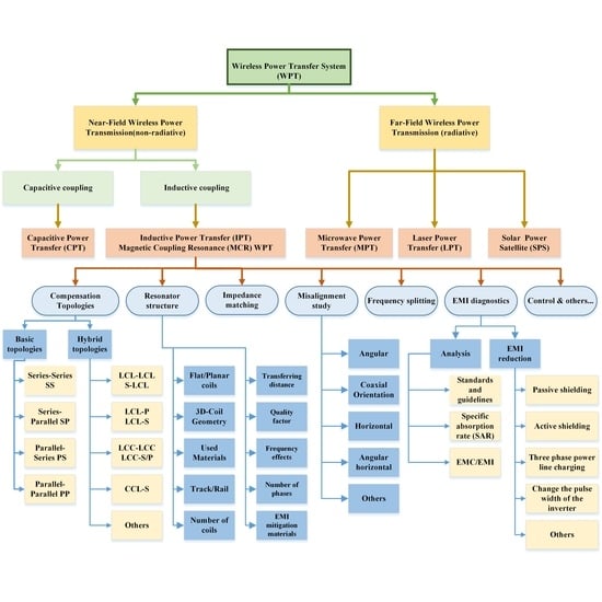
According to the energy transfer mechanism, the WPT technology can be divided into two categories. The first is far-field wireless transmission, which is also called electromagnetic radiation WPT. It includes microwave power transfer (MPT) [40,41,42], laser power transfer (LPT) [43,44,45], and solar power satellites (SPS) [46,47].
The second is near-field WPT (Figure 1), which can, in turn, be classified into two groups. Firstly, there is inductive power transfer, including the inductive coupled power transfer (ICPT or IPT), and magnetically coupled resonance wireless power transfer (MCR WPT); as shown in Figure 1a, Tx is the transmitting coil and Rx is the receiving coil. Secondly, there is capacitive power transfer (CPT), as displayed in Figure 1b. Some IPT systems have presented high power transmission efficiency (PTE) of larger than 90% for transmission distances of several centimeters; however, for longer distances, efficiency will drop significantly [48,49,50,51,52,53,54,55,56,57,58,59,60,61,62,63]. Nevertheless, authors have presented an innovative IPT system to transfer power a distance of 5 m using dipole coils [64]. Most of the presented CPT systems are designed for low-power applications, including USB devices, lamps, and small robots [8,65,66,67,68,69,70,71,72,73], where the transmitting distance is limited to the millimeter range. High efficiency is provided by MCR WPT for a longer transferring distance [23,34,74,75,76,77,78,79,80,81,82].
Due to its importance and rapid development, WPT has been widely used over the last few years, offering a practical technique to transfer power wirelessly in many applications on a commercial scale. Many studies have been conducted in this area, and the literature has reported much research related to several aspects of MCR WPT, which is usually confusing and difficult to follow. To give a clear picture, this paper aims to review the recent contributions to the current state of MCR WPT systems. This paper sets a benchmark in order to provide comprehensive classifications with a deep comparison between different WPT systems according to different criteria. They are as follows:
- Compensation topologies: Basic and hybrid compensation topologies are reported, and some commonly used topologies are compared based on application type.
- Research work related to the resonator structure is discussed as follows:
- Coil geometry is discussed in detail, including many resonator shapes, such as planar coils, three-dimensional (3D) structures, cavity structures, and coils with cores, etc., which are compared based on set criteria.
- The differences between single-phase WPT and three-phase WPT systems are highlighted, and some three-phase WPT projects are reported.
- Multi-coil systems, which are capable of charging multiple devices simultaneously, such as LEDs, are addressed.
- Operating frequency effects on the design of coil structure.
- Inductance of several resonator structures.
- Misalignment study: Several misalignment types are displayed and compared based on their resonator structure and effects, in addition to their advantages and disadvantages.
- Electromagnetic field interference (EMI) diagnostics, including WPT-related standards and guidelines. In addition, EMI and EMF reduction methods are reported and compared. Moreover, advantages and disadvantages of these methods are addressed.
- Basic applications of WPT systems are given. Next, a WPT case study is proposed. In the proposed winding method, a bio-inspired joint made of two spherical structures is given. The algorithm design is provided, and experiments are conducted to validate the obtained results by simulation and optimization.
The paper is organized as follows. In Section 2, a benchmark is set to present the major categorizations of the WPT system. Section 3 discusses compensation topologies in detail. Section 4 classifies and reviews many resonator structures in detail. The misalignment study is presented in Section 5. WPT-related standards, electromagnetic field (EMF) mitigation methods, and EMI mitigation methods are given in Section 6. In Section 7, WPT applications are illustrated, an optimized design of a WPT system is given, and a case study is proposed and discussed. Finally, the conclusion and further areas for research are provided in Section 8.
2. Benchmark of the Research Work
In this paper, a benchmark is proposed (Figure 2) that provides various categorizations of research works related to WPT. The benchmark classifies major research areas relating to WPT, which include compensation topology, resonator structure, misalignment study, EMI and EMF diagnostics, frequency-splitting issue, impedance matching, control strategy, and WPT optimization. In this paper, a number of these issues related to WPT systems are discussed in detail. Other issues, such as impedance matching (which will be discussed in brief in Section 3) and control methods [83,84], will not be discussed for the sake of brevity.
3. Compensation Topologies
There are some requirements for compensation, which are as follows. (1) The compensation capacitor resonates with the primary and/or secondary inductance in order to provide reactive power, which is required for the inductances to generate an adequate magnetic field. Therefore, the basic function for the compensation of a primary coil is to minimize the volt-ampere (VA) rating of the power supply. In the secondary coil, compensation cancels the inductance to maximize the power transfer capability [85]. (2) Constant-voltage/constant-current output (CVO/CCO). (3) The maximum efficiency of a WPT system can be determined by two parameters, the coupling coefficient and quality factor [54]. (4) Bifurcation resistance, which refers to a condition where the frequency realizes a zero phase angle (ZPA) [57,85].
3.1. Basic and Hybrid Compensation Topologies
Figure 3 shows the classifications of the compensation topology. They include two groups. The first is of the four basic topologies, and the second comprises hybrid topologies, which are combinations of series and parallel topologies.
Many compensation topologies have been reported. As illustrated in Figure 4, there are four basic compensation topologies: series-series (SS) [3,86,87,88,89,90], series-parallel (SP) [91], parallel-series (PS) [1], and parallel-parallel (PP) [92]. In Figure 4, k is the coupling coefficient, M is the mutual inductance, Ug is the input voltage on the primary side, U2 is the load voltage, and RL is the load. L1, L2, C1, and C2 are the self-inductances and external compensation capacitors of the primary and secondary coils, respectively. R1 and R2 are the resistances of the primary and secondary coils, respectively. On the other hand, hybrid compensation topologies are investigated, such as LCC-P and LCL-P are reported in [93], where LCC and LCL are on the transmitting side, and parallel (P) is on the receiving side. Moreover, S-CLC [94], CCL-S [95], LCL-S [96], and LCC-LCC [18,97,98,99] are discussed. Double-sided LCC-compensated WPT (multi-LCC on the transmitter side) is presented in [100], and LCL-LCL is given in [101]. Some commonly used hybrid topologies in the research work are displayed in Figure 5. Lp and LS are the primary and secondary inductances, respectively.
3.2. Review of Different WPT Systems Based on Topology and Application Type
Table 1 gives a comparison between different WPT systems based on the compensation topologies and application type (electric vehicles). The systems are easily compared considering some criteria, such as transferred power, frequency, resonators’ dimensions, and transferring distance. In this table, f0 is the resonant frequency, k is the coupling coefficient, and RL is the load value. In addition, N1 and N2 are the number of turns for primary coils and secondary coils, respectively. D1 and D2 are the length (or diameter) and width (or diameter) of the transmitter and receiver coils, respectively. Finally, Pout is the output power and Vout is the output voltage. Table 2 reviews the WPT systems that are used in dynamic charging for EVs application.
In PS-compensated WPT, the reactive current of the current-fed resonating converter circulates inside the parallel resonant tank without going through the switching system. Therefore, the current rating of the switching devices is reduced, and the conduction loss is reduced for a given power level. This topology has a high voltage stress on the inverter switches, especially for high power loads, and it becomes worse when the coupling coefficient is low. CCL-S is an example of hybrid topologies; as shown in Figure 5c, it has an extra series capacitor on the primary side, which leads to a lower switching loss compared to the parallel LC-S. Parallel LC-compensated WPT is preferred for low voltage gain applications. However, for higher voltage gain, CCL is preferred. S-CLC topology, which is shown in Figure 5a, provides an easier achievement of ZPA. In Figure 5k, the double-sided LCC-compensated topology was illustrated, and a continuous dynamic WPT charging system was introduced.
The output current and output voltage of SS, S-LCL, S-CLC, and SP compensation topologies are inversely proportional to the mutual inductance, and the output power is inversely proportional to the square of the mutual inductance. Regarding double-sided LCL, as well as double-sided LCC, LCL-S, LCL-P, PS, and PP compensation topologies, the output current and output voltage are proportional to the mutual inductance, and the output power is proportional to the square of the mutual inductance. Based on that, the design method of these topologies can be determined. Consider two cases. The first is an SS-compensated WPT system, which is designed to transfer a nominal power at the maximum mutual inductance, and means perfectly aligned coils. At the maximum mutual inductance, the input voltage and efficiency of the SS topology will be higher, and the current will be lower. The second is an LCC-compensated WPT system, which is designed at the minimum mutual inductance, and means a maximum misalignment between resonators.
Finally, at high-frequency circuits, there arises an impedance matching problem, where the circuit components gain a non-resistive aspect. To achieve maximum power transfer efficiency, the circuit must be impedance matched to minimize these effects [106,107]. Some impedance-matching methods were proposed, such as employing the impedance inverter only at the receiver side [108], and using a dual-band resistance compression network (RCN) as a matching network [109].
4. The Resonator Structure
Figure 6 shows the research work related to the resonator structure (geometry) including several categories, such as planar coil, 3D structures, tracks/rail, coils with cores, and the type of used materials, etc. In addition, the suitable application type for each structure is given, and the frequency ranges for some of these geometries are provided.
4.1. Shape of the Resonator
Different studies have been investigated based on the shape of resonators. They are classified as follows:
- Flat/planar-shaped coils, such as rectangular-shaped structure [89,98,110,111], octagonal resonator [101], and a double D coil (DD) [112]. In addition, defected ground structure (DGS) is presented in [113,114]. DGS means a “defect” has been integrated on the ground plane of a microwave planar circuit; this DGS technique is adopted to improve various parameters of a microwave circuit, such as low gain and narrow bandwidth [115]. Moreover, circular coils [116,117] and square coils [99,118,119] are discussed. There are planar printed spiral coils (PSC) [120,121,122,123] as well, the WPT system in the printed circuit board (PCB) [124,125,126,127], pancake coils [128], and planar shielded-loop resonators [129].
- Three-dimensional (3D) geometries are investigated, such as for instance, bowl-shaped transmitter coils [28], which are used for charging hearing aids, cylindrical coils [80], helix loop resonators [130,131,132,133], and conical coils [134]. In [135,136], the three-dimensional resonant cavity is presented, which offers a good way of charging multiple devices simultaneously. An orthogonal winding is discussed in [137], and a cylindrical cavity is given in [138]. In [139,140,141,142], the authors proposed an omnidirectional WPT system, and in [143], the authors discussed a ball joint structure.
- Coils’ materials are discussed, for example, a receiver coil made of aluminum is used in [125]. In [144], the authors proposed a helical-type coil made of superconductors in order to increase the quality factor of the coils. In [145], the authors applied an MCR WPT system (planar textile resonators, or PTRs) to wearable consumer electronics by using flexible materials.
- Coils with cores are given, such as dipole-type coils [64], which presented a WPT prototype that is capable of transferring the power up to a 5-m distance. For charging vehicles, buses, trams, and trains, long-track transmitter and short-individual tracks are used [16,17,90]. Moreover, E-core and U-core types are discussed [94,146].
Other structures were presented, for example, multiple-input multiple-output structures (MIMO) [147,148], a wirelessly powered cage system [149], transparent electrode resonators [150], domino-resonator systems [151,152,153], and dual-layer nested structures [154]. Moreover, the three-phase system [16,35,155] found its way to the wireless charging technology through some real applications. Finally, an L-shape transmitter was discussed in [156].
Most of the resonators are coreless, which means no iron losses (hysteresis loss, eddy current). However, the quality factor, and thus the efficiency, will be low. To overcome this problem, there are three options. The first is increasing the mutual inductance by changing the geometry or increasing the number of turns and adding ferrites. However, in some cases, ferrite cannot be added due to cost and space limitations. The second is increasing the frequency, but it could be limited by the switching speed of the semiconductors, and it might cause more switching losses. The third is using multi-transmitter WPT systems, but resonant inverters with different power rates are required.
Table 3 presents projects related to the defected ground structure (DGS). The defected ground structure (DGS) can operate at high frequencies, for example, the spiral-strips DGS operates at 50 MHz, which provides a high-quality factor and introduces a structure that mitigates the problem of a low self-inductance that is given by H-shaped DGS. Compared to H-shaped DGS, the semi-H-shaped DGS shows a better efficiency and greater transferring distance even if they have the same size. In Table 4, the three-dimensional resonant structures are reported and compared. Cylindrical, helical, and cavity structures are used to provide power for some applications, such as hearing aids, LEDs, and toys.
Table 5 displays studies related to flat structure, in which the power transferring distance is almost twice the radius/width of the coil, and the power range is within several watts to several dozen watts of power. Table 6 gives two cases of WPT systems using coils with cores. Several core types are used, especially in EV charging applications. Table 7 reports research works on domino resonator systems for low-power applications.
The circular, spiral circular, square, and rectangular geometries are widely used due to their simple design and low manufacturing cost. To give a clearer picture of the circular and rectangular coils, new classifications (concluded from the above-mentioned tables) are presented in Table 8 and Table 9, respectively. Comparing the size of the coils, the transferring distance, and the operating frequency, the systems will show approximate results.
In EV charging application and due to space limitations, some structures, such as the helix, omnidirectional, cavity, or conical, cannot be used. However, the resonators are designed as spiral or planar coils. These geometries are printable and easy to implement at a low cost. Moreover, the dynamic charging systems are used, and according to the track length, they can be divided into two categories. The first is the long-track transmitter, which can charge multiple vehicles simultaneously. This system is simple and has a low number of components. The online electric vehicle (OLEV) with a maximum charging power up to 100 kW is one example. However, this design has a low efficiency of 74%. The second is the short-individual transmitter, where the length of the transmitter is usually within 1 m. In this system, each transmitter has a compensation circuit. Therefore, multiple short transmitters are arranged in an array to make a tracking lane, and the transmitters can be excited based on the location of the receiver. This structure is considered flexible, but requires a large number of circuit components and converters.
There are other architectures used in EVs; for example, in [104], the Oak Ridge National Laboratory (ORNL) presented an in-motion charging system for EVs/PHEVs, which transfers the power to a moving receiver coil as it passes over two transmitting coils connected in series. In this system, the coil design depends on jacketed Litz cable coils over a structure of soft ferrite. The Research Centre for Energy Resources and Consumption (CIRCE) in Spain proposed a receiver, which is longer than the transmitter [157]. In [105], the influence of the difference of the ratio between the receiver length and the transmitter length is investigated. The structure is a couple of unipolar square-shaped pads made of a copper coil, and a metallic plate, which represents the floor of the vehicle chassis, was placed 25 cm above the transmitter. In [158], the authors presented an overview of the current studies related to automotive applications, such as Korea Advanced Institute of Science and Technology (KAIST) projects on an OLEV bus, HalolPT, which developed IPT solutions in a power range of 3.3–20 kW, and WiTricity (MIT), which proposed a 3.3-kW system that has been proven. In addition, Plugless Power is a 3.3-kW IPT stationary charger, which was developed by Evatran and Bosch.
Based on the number of phases, WPT systems can be divided into two sections: single-phase systems and three-phase systems. The three-phase WPT systems that operate at symmetrical conditions and similar phase currents have two essential benefits compared to the single-phase systems: they have higher power level and better far-field EMC performance due to the three magnetic fields’ superposition. In addition, they have very small power ripples on the DC output [159]. The three-phase WPT system found its way to some practical applications, for example, in [16], authors proposed a three-phase WPT system, which has six overlaid power lines and ended in two Y-points; each power line is symmetrical from its center, as a result, it can reduce the leakage magnetic field. In [35], the authors proposed a three-phase WPT, which can be used in recharging AUVs. A continuous charging system without onboard batteries was proposed [49]. In this system, charging the batteries along roadways is not required. Therefore, there was no need for complicated pickup structures. For heavy-duty applications, a tuning approach for the three-phase WPT with a long track is presented [160]. There are some high power three-phase WPT systems in operation, such as the Brunswick and Berlin buses with a maximum power of 200 kW based on Bombardier PRIMOVE technology.
4.2. Size and Number of the Resonators
Comparing the transmitter and receiver coils according to their size, they can be either symmetrical or asymmetrical. The first one is the symmetrical coils, where the transmitter and the receiver coils have the same size [94,110,117]. However, in the asymmetrical coils, the transmitter and receiver coils have a different size [80,118,136]. WPT systems can be categorized according to the number of coils, as shown in Figure 7, where they can be classified as follows: two-coil structure (2C) [64,113], three-coil structure (3C) [116,132], four-coil structure (4C) [119,122], and multi-coil structure (MC) [136,151,152]. The strongly coupled magnetic resonance (SCMR), which is a 4C system, is classified into four systems [161]: a standard SCMR system, a conformal SCMR (CSCMR system), a 3D SCMR, and a hybrid SCMR (HSCMR). Generally, the two-coil system saves more space than the other systems. However, the three-coil or four-coil systems allow transferring higher power for a longer distance.
The multi-coil system is capable of charging multiple devices simultaneously. A WPT system that consists of a single transmitter and multiple receivers is investigated [32], and considered the influence of load and mutual inductance (the position of receivers) on the efficiency. A multi-coil transmitter array is employed to boost the power gain, which in turn allowed the application of very small receivers at a quite far distance [77]. A power transfer from a single source coil to multiple receivers through MCR WPT was demonstrated [162]. In addition, a WPT system based on the resonant cavity is proposed [136], and provided an efficient power delivery to many receivers simultaneously in an enclosed 3D volume of space (charging multiple toys that are placed randomly in a box or charging multiple LEDs). WPT systems based on the resonant cavity have the potential to enable a wide variety of new applications in many medical and industrial fields. However, this system has a problem in distributing the power uniformly to many receivers, especially in wearable devices or IMDs. To overcome this issue, a selective technique for smart power delivery to multiple receivers is presented [163]. The method allows transferring the power to one receiver coil among multiple receivers by separating the resonant frequencies of the receivers, and isolating the cross-coupling effects between the coils.
4.3. Loop Inductance
Table 10 provides the self-inductance formula for some resonator shapes, such as square, rectangular, circular, and so on [164,165]. Table 11 gives layout dependent factors (xi) for on-chip spiral inductors, such as square, hexagonal, octagonal, and circular [124].
Coil design is a basic step in WPT systems, since it determines the level of power transfer, efficiency, and the overall performance [104]. Therefore, the inductance is considered one of the most significant factors in the WPT system. The inductance depends on the coil geometry, which includes the size of the resonator, cross-sectional area, length, and number of turns, in addition to the separation between turns and thickness or width of copper.
4.4. Operating Frequency Effects on the Design of Coil Structure
An ideal inductor can be modeled as an inductance with no resistance, capacitance, or energy dissipation. On the other hand, for real inductors, as shown in Figure 8, the above-mentioned components are inevitable. The wire has a resistance (Rac) and losses in the core materials. In addition, there are parasitic capacitances (Cself) caused by the electric field between the turns. The parasitic capacitance with the self-inductance can determine the self-resonant frequency (SRF) of the coil. At high frequencies, the effect of these factors will be obvious, and the AC resistance value will increase due to the skin effect. Therefore, the quality factor of the coils will drop. Due to high frequency, the current will be concentrated near the surface of the copper conductor, and as a result, the power loss will increase and cannot be ignored [166].
The inductance and skin effect are given as follows [162]: , (m), respectively. In the previous equations, r is the radius of the coil, d is the radius of the wire, and σ is the conductivity; for copper, σ = 5.8 × 10⁷ (S/m) and μ0 = 4π × 10−7 (H/m). Figure 9 presents a copper conductor with a 0.5-mm radius. When the frequency increases, the skin effect will be clearer. In order to reduce the AC resistance and power losses, Litz wires (multi-strand wires) are used to wind the coils. Based on the operating frequency range, the required diameter, and the number of wire gauge of the Litz wire can be determined [146]. In addition, superconducting materials were used to decrease the resistance and achieve a high-quality factor [144].
Finally, the frequency-splitting issue is a key point of an MCR WPT system. When moving the resonators toward each other gradually, the coupling between them becomes stronger, and if they are close enough, the resonant frequency will change. As a result, the transferred power drops sharply [167]. To clarify this case, Figure 10 shows two spherical structures for a WPT system, where the transmitting coil Tx is in blue, and the receiving coil Rx is in orange (the spherical joint structure for a WPT will be discussed in the seventh section). The coil windings are wound in different ways. In Figure 10a, Tx and Rx are located opposite to each other, and the coupling coefficient will be k = 0.089. Figure 10b displays the efficiency at the resonant frequency (500 kHz). In Figure 10c, Tx and Rx coils are wound in the same direction as the hemispherical structures. As a result, this model will have a short transferring distance, and the coupling coefficient will be high k = 0.54. Figure 10d illustrates the efficiency at the resonant frequency (500 kHz).
To deal with the frequency-splitting issue and power transfer degradation, several methods are presented, such as an adaptive frequency tracking method, which changes the frequency in the strongly coupled region [168]. Instead, the frequency-splitting issue is suppressed by switchable configurations, such as for example, a switchable capacitor array [169], alternative multiple loops [170,171], and various load resistances [172].
5. Misalignment Study
In order to get a higher power transfer efficiency (PTE), the alignment between the WPT resonators should be perfect. However, the coils are usually misaligned [119]. There are several types of misalignment between the coils, which include the following. (1) In lateral (horizontal) misalignment, the coils are located in parallel planes, but they are offset by distance Δx. (2) In angular misalignment, the receiver coil is moved by an angle ϑ while the centers of the transmitter and receiver coils are well aligned [173]. (3) In vertical variation, the receiving coil moves vertically. (4) In planar misalignment, Tx and Rx are in parallel, and Rx rotates around the center point, but keeps the same transferring distance. (5) In angular azimuth misalignment, the transmitter is fixed, and the receiver rotates around the z-axis in the x-y plane from φ = 0° to φ = 360°. (6) In angular elevation misalignment, the receiver rotates around the x-axis in the y-z plane from θ = 0° to θ = 360°, and the transmitter is fixed [161].
Figure 11 displays different types of misalignment. This figure has shown a circular resonator to present misalignment types. However, the same misalignments apply to other structures as well, such as rectangular, square, and hexagon.
Table 12 compares between different misalignments considering the coil structure and misalignment effect; some notes related to each type are given in comments.
The misalignment differs randomly under different situations and different application types. As a result, several parameters may change during the process, such as the mutual inductance, the efficiency, and output power. During the EV’s charging, if there is imperfect parking, the transmitter and receiver coils will be misaligned. The transmitter coil is fixed on/under the ground, and the receiver is mounted on the bottom of the vehicle. In IMDs applications, if the patient breathes, the air gap of the WPT will change. Therefore, it is important to predict the misalignment tolerance of the WPT system in different applications. In addition, the system needs good controllability and optimization to deal with its parameter variations.
6. EMI and EMF Diagnostics in the WPT System
The electromagnetic spectrum includes two sectors. They are as follows. The first is the non-ionizing area, which means the energy of the waves is too low to ionize tissues. The second is the ionizing radiation area. MCR WPT products use electromagnetic waves within the non-ionizing area of the electromagnetic spectrum.
6.1. WPT-Related Standards, Including the Safety Issues
Regarding safety issues linked to WPT usage, there are two serious issues. The first is that long-term exposures to time-varying EMFs can harm the human body. Therefore, the International Commission on Non-Ionizing Radiation Protection (ICNIRP), expert groups, and the World Health Organization (WHO) have documented and issued some guidelines to ensure the safety of the human body. The second is a wide range of harmonics generated by inverters, which in turn create EMI issues on the other electronic devices’ operations. Therefore, it is important to suppress EMF and EMI in the WPT system [174].
Based on the obvious risks that are caused by using the WPT charging systems, it is necessary to regulate the usage of the WPT systems. Therefore, many recommendations, standards, and guidelines were issued. Table 13 provides a comprehensive review of WPT-related standards and guidelines that were issued by different international organization around the world. For example, in order to protect against any known health effects, the ICNIRP has published guidelines for maximum exposure limits. They consist of the publications from 1998 (0 Hz–300 GHz) and 2010 (0 Hz–100 kHz).
Table 14 presents the near-field WPT systems, including the frequency and power ranges under study in non-ISM bands for Japan and South Korea.
It is inevitable for the electrical circuits and the human body that are close to the WPT system to be under the influence of EMI emissions or exposure to EMFs. Therefore, it is essential to regulate the deployment of the WPT system to ensure the safety of the consumers and electrical components. The standards differ from one country to another. Therefore, the WPT system can be categorized based on the frequency, power, transferring distance, and application type. As a result, the WPT system is handled as normal equipment that follows specific restrictions, or it is considered an important case that follows tighter restrictions.
6.2. EMF and EMI Mitigation Methods
Some WPT charging applications have a large air gap, such as EVs, where it can reach 10–30 cm. This creates high levels of a stray field in the coils’ vicinities, thus arises an issue regarding the exposure to magnetic fields for people who approach the vehicle or passengers during the charging process [175]. In [175], the authors presented a pulsed magnetic fields methodology (developed according to the requirements of the International Commission on Non-Ionizing Radiation Protection (ICNIRP) guidelines), the results for the assessment applied to a 20-kW IPT system for dynamic charging of EV at the frequency of 85 kHz. The charging is performed by using several independent transmitters (each one: 1.5 m long and 0.5 m wide). When the vehicle is above them, they will be activated. In this direction, the authors investigated the human exposure to the EMFs by using a computational modeling applied to a 7-kW WPT charging system at the frequency of 85 kHz [176]. In [177], two-step scaled frequency finite-difference time-domain (SF-FDTD) methods are used to calculate the internally induced electric fields in the human body.
EMF safety can be achieved through the magnetic field level reduction in the near-field area. Therefore, several reduction methods were presented, such as using ferrite materials [14], metallic materials (aluminum) [178,179], and metamaterials (MM) [180,181,182,183]. Changing the pulse width of the inverter to decrease the harmonics of the leakage electric field was presented [184]. In [185], the authors presented three active methods that include the independent self-EMF cancelation (ISEC), the 3-dB dominant EMF cancel method (3DEC), and the linkage-free EMF cancel method (LFEC). In addition, the authors have reported other techniques, such as separating pickup rectifiers and magnetic mirror methods. In [7], the authors presented a resonant reactive shield with one coil and a capacitor. In [186], a resonant reactive shield with two coils and four capacitors was discussed. Figure 12 illustrates the above-mentioned EMF mitigation methods. On the other hand, some EMI mitigation methods are reported, for example, the spread spectrum clock technology (SSC) [187]. In [174], the authors investigated an isolation inductor scheme to reduce EMI in an automotive tightly coupled handheld resonant charging system. Moreover, EMI can be suppressed by optimizing the rise and fall times of the output voltage in high-frequency soft-switching converters [188].
Table 15 compares between different EMI and EMF mitigation methods, in addition to their advantages and disadvantages.
7. WPT Applications: An Optimized Case Study
Figure 13 summarizes many applications of a WPT charging system, and shows that the WPT became an important part of some basic fields. First, in transportation, wireless power transfer for electric vehicles is a promising technology. Secondly, in the implantable medical devices (IMDs), it gives a convenient, reliable, and safe way to supply the power wirelessly without any pain to patients. Thirdly, in the field of consumer electronic applications, WPT is used in LED TVs, charging portable devices, such as cell phones, tablets, and other smart building appliances, where the WPT technology reflects the development of this kind of buildings. Moreover, the WPT system is used in IoT applications. Finally, WPT systems are used in LED lights, underwater detection, military defense systems, space applications, etc.
To give a clear picture about the design method for a certain application, a 3D structured WPT that transfers the power wirelessly in a robotic application is proposed. The system is a bio-inspired joint for the WPT system. The joint consists of a movable spherical structure that rotates inside a big sphere using a mechanical stud (0°–85°). The transmitter coil (Tx) is wound on a hemispherical structure, as shown in Figure 14a, or wound on a spherical structure (with a slot), as shown in Figure 14c. In this case, the mechanical stud can rotate the small sphere up to 45°. The receiver coil (Rx) is wound on the small sphere structure. α is the displacement angle (degrees) between the vertical axes of the joint structures.
To design the WPT system, Figure 15 is illustrated. Considering the transferred power, frequency, structure, and other parameters, the purpose of the WPT system should be determined. The application type has two types of constraints, which include the structure and electrical constraints. The structure constraints include the size, volume, and gap. The electrical constraints comprise the compensation topology and its parameters, the required power to be transferred, and the operating frequency. On the other hand, several variables are parameterized to optimize the WPT, such as for example, the mutual inductance M, the output power, and the efficiency. WPT optimization is achieved by simulation and calculation, and experiments are put forward to validate the obtained results. Other factors can be considered during the design, such as suitable EMI and EMF mitigation methods (based on the application type).
7.1. Optimization Method
The power transfer efficiency (PTE) is a key design factor of the WPT system while operating over the resonance frequency. PTE optimization depends on the mutual inductance (M). M is proportional to the square root of the transmitter and receiver inductances L1 and L2, respectively. Therefore, the WPT system is optimized by changing the shape of the winding coils to maximize the mutual inductance (SS-compensated WPT) and reduce its fluctuation during the angular displacement. Several variables are considered to parameterize the coils, such as the number of turns, space between turns, and variation in the z-axis position.
Figure 16 presents the joint-WPT system in the y-z plane. The transmitter coil has N1 turns, and the receiver coil has N2 turns. ri is the radius of each horizontal turn of the transmitter coil at a zi (z-position). rj is the radius of each horizontal turn of the receiver coil at zj (z-position). The radius of the transmitter coil is already given by rs = 3.85 cm, and the radius of the receiver coil is given by rb = 2.85 cm.
The algorithm design is written as follows:
- The size constraints: 0 ≤ zi ≤ rs; the turns cover the whole space of the hemisphere of the transmitter structure, which means: 0 ≤ Ɵ ≤ (π/2). On the other hand, 10 ≤ zj ≤ 2 rb; the turns cover the whole space of the small sphere, which means: 0 ≤ β ≤ (π). The pitch between turns is set to P = 0.5 mm.
- Initialize zi, β, and Ɵ as 0. Initialize zj = 10 mm (start z-position for Rx), N1 = 0, N2 = 0, m = 0, and n = 0.
- Enter the radius of the transmitter coil rs = 38.5 mm, the radius of the receiver coil rb = 28.5 mm, and the pitch between turns P.
- Enter β and Ɵ. // Measured in radian.
- Count: Ɵ = Ɵ + (1/36) π, β = β + (1/36) π, N1 = N1 + 1, N2 = N2 + 1, zim = zim + P, and zjn = zjn + P, n addition to m = m + 1 and n = n + 1. // Increment angles to determine the z-position and r for each turn of the transmitter and receiver coils. ((1/36) π is the assumed step). Increment N1 and N2 to find the number of turns for both coils. Move the turns in the z-direction with the pitch between coils equal to 0.5 mm. The number of turns can be calculated by N1 = zim/P and N2 = zjm/P.
- Calculate rim = rs sin (Ɵ), rjn = rb sin (β), zim = rs (1 − cos (Ɵ)), and zjn = rb (1 − cos (β)). // mm (based on angles).
- Calculate L1 and L2: the self-inductances of the transmitter coil and receiver coil, respectively. Calculate and maximize the mutual inductance M and the coefficient coupling k, and determine the required capacitors C1, C2. // In order to maximize the mutual inductance, the inductances will be adjusted based on the number of turns and the space between turns (pitch). The transferring distance between Tx and Rx will determine the coupling coefficient, which should be less than a certain value ks.
- With the available values of the frequency and coil resistance, calculate the quality factor, transferred power, and efficiency.
- Sweep the frequency and mutual inductance to maximize the efficiency and transferred power.
- Is k < ks, if yes, go to 11, or else go to step 13. The coupling coefficient should stay within a certain range to avoid cases with very low values or cases with very high coupling between Tx and Rx.
- Is Ɵ < π/2, if yes, go to step 12, or else go to step 13.
- Is β < π, if yes, go to step 3, or else proceed to step 13.
- End.
Figure 17 illustrates a flowchart that represents the algorithm design.
7.2. Simulations
The simulation of the joint WPT system is conducted by ANSYS electronics 19.0.0, USA, 2018. The optimization process has resulted in cases with high coupling coefficient values and others with low values. As shown in Figure 18, two cases are considered. The first is the hemisphere winding with a high coupling coefficient (k = 0.54). The second is the optimized model with k = 0.089. The obtained parameters are given in Table 16.
Figure 19 shows that the mutual inductance and coupling coefficient for the hemisphere-winding drop rapidly with the angular misalignment, which can, in turn, lead to low efficiency. However, with the optimized solution, the fluctuation of M and k is reduced, and the performance of the WPT system is improved. Therefore, the receiver can rotate inside the transmitter from zero degrees (perfectly aligned coils) up to 90 degrees (practically 85°) while keeping high efficiency. Figure 20 shows the relation between the efficiency, load, and resonant frequency. For the hemispherical winding at a load of RL = 20 Ω, the efficiency was up to 96% at α = 0°. However, at α = 85°, the efficiency dropped to lower than 10%. On the other hand, for the optimized WPT with the same load, the efficiency was up to 95.75% at α = 0° and 96% at α = 85° (the mutual inductance at 85° is higher than that at 0°).
Figure 21 presents the magnetic field density for the optimized and hemisphere models. The magnetic field density is given by B = µH, where H is the magnetic field strength (intensity) measured by (A/m). In Figure 21a, at α = 0°, the yellow area (within 12-cm diameter) shows that B is around 86 µT, which is higher than the allowed level by ICNIRP 2010 (should not exceed 27 µT). In Figure 21b, the magnetic field density is concentrated in the close area around the coils. These cases require attention if the WPT is deployed close to the human body or other sensitive circuits. EMI and EMF mitigation methods can be selected based on the cost, weight, and size constraints of the joint. For instant, choosing ferrites is not a good choice, since it will put more pressure on the robotic arm. Based on the simulation results, a thin light sheet of aluminum can reduce the magnetic field density around the joint WPT to a safe level.
7.3. Experiments of the Proposed WPT and Measurements
The WPT system is fabricated to validate the calculated and simulated results. Figure 22 presents the experimental setup, where a multi-strand Litz wire was used to wind the coils. Radio frequency (RF) Mica-type capacitors CDE (CD15FA102JO3F) and a half-bridge inverter were used. The system is SS-compensated WPT, and the experiments included two models, as presented in Table 16.
Figure 23 shows the input and output voltages at the resonant frequency (496 kHz) for the hemisphere-winding in Figure 23a, and the optimized model in Figure 23b.
The angular misalignment effects on the input and output voltages are given in Figure 24 and Figure 25. In this structure, the receiver coil can rotate up to 85°. At α = 85°, for the hemisphere-winding, the output voltage will drop to values close to zero. However, for the optimized model, even at α = 85°, the output voltage keeps a high value.
7.4. Cost Assessment of WPT Systems
The cost assessment of the WPT system can be done by considering the number of required components, such as inverter switches, diodes, Litz wires, resistors, capacitances, etc. In general, compared to hybrid topologies, the SS, SP, PS, and PP compensation topologies require fewer components. At kHz-range frequencies, high output power could be needed, and the power converters are added. As a result, the total cost is increased, such as EV charging applications that operate at 20 kHz and 85 kHz. At high frequencies, the output power could be very low, and the system does not require additional components such as IMDs that use the ISM band (2.2 MHz and 6.78 MHz).
8. Conclusions and Future Research
This paper has comprehensively reviewed the recent progress of the MCR WPT system including several aspects, such as compensation topologies, resonator structures, and misalignment analysis. In addition, EMI and EMF diagnostics were discussed, and the WPT-related standards were reviewed. Moreover, several EMI and EMF mitigation methods were reported and compared. Furthermore, a wide range of WPT applications was presented. Finally, a WPT case study was proposed. In the proposed winding method, a bio-inspired joint made of two spherical structures was given. The design process and algorithm design were provided, and experiments were conducted to validate the obtained results by simulation.
As shown in Figure 26, to work toward an optimum design of WPT, there are some factors that have an impact on the design process and thus should be considered during the design and manufacturing process. The application type is determined by considering the size or volume, the transferring distance, the required power to be transferred, and the operating frequency. After that, inductances, resistances, quality factors, and mutual inductance are obtained. Choosing a proper compensation topology is another basic step. Other factors are considered, such as suitable EMI and EMF mitigation methods. Therefore, a good combination of the above-mentioned factors has to be considered. Even though many studies have been investigated, research related to new topologies, novel structures, new materials, and mitigation methods, in addition to system stability under misalignments, impedance matching, control strategy, and cost-effective assessment should be done.
Author Contributions
M.A.H. conducted the review and wrote the manuscript. X.Y. and W.C. Guided and contributed in discussions and supervision.
Funding
This research received no external funding.
Acknowledgments
The authors would like to thank the anonymous reviewers for their constructive comments.
Conflicts of Interest
The authors declare no conflict of interest.
References
- Liu, F.; Yang, Y.; Jiang, D.; Ruan, X.; Chen, X. Modeling and Optimization of Magnetically Coupled Resonant Wireless Power Transfer System with Varying Spatial Scales. IEEE Trans. Power Electron. 2017, 32, 3240–3250. [Google Scholar] [CrossRef]
- Miller, J.M.; Onar, O.C.; Chinthavali, M. Primary-side power flow control of wireless power transfer for electric vehicle charging. IEEE J. Emerg. Sel. Top. Power Electron. 2015, 3, 147–162. [Google Scholar] [CrossRef]
- Hsieh, Y.C.; Lin, Z.R.; Chen, M.C.; Hsieh, H.C.; Liu, Y.C.; Chiu, H.J. High-Efficiency Wireless Power Transfer System for Electric Vehicle Applications. IEEE Trans. Circuits Syst. II Exp. Briefs 2017, 64, 942–946. [Google Scholar] [CrossRef]
- Mou, X.; Groling, O.; Sun, H. Energy efficient and adaptive design for wireless power transfer in electric vehicles. IEEE Trans. Ind. Electron. 2017, 64, 7250–7260. [Google Scholar] [CrossRef]
- García, D.T.; Vázquez, J.; Roncero-Sánchez, P. Design, implementation issues and performance of an inductive power transfer system for electric vehicle chargers with series–series compensation. IET Power Electron. 2015, 8, 1920–1930. [Google Scholar] [CrossRef]
- Li, S.; Mi, C. Wireless power transfer for electric vehicle applications. IEEE J. Emerg. Sel. Top. Power Electron. 2015, 3, 4–17. [Google Scholar]
- Kim, S.; Park, H.H.; Kim, J.; Kim, J.; Ahn, S. Design and analysis of a resonant reactive shield for a wireless power electric vehicle. IEEE Trans. Microw. Theory Tech. 2014, 62, 1057–1066. [Google Scholar] [CrossRef]
- Zhang, H.; Lu, F.; Hofmann, H.; Liu, W.; Mi, C. A Four-Plate Compact Capacitive Coupler Design and LCL-Compensated Topology for Capacitive Power Transfer in Electric Vehicle Charging Application. IEEE Trans. Power Electron. 2016, 31, 8541–8551. [Google Scholar]
- Dai, J.; Ludois, D.C. Capacitive power transfer through a conformal bumper for electric vehicle charging. IEEE J. Emerg. Sel. Top. Power Electron. 2016, 4, 1015–1025. [Google Scholar] [CrossRef]
- Choi, S.Y.; Gu, B.W.; Jeong, S.Y.; Rim, C.T. Advances in wireless power transfer systems for roadway-powered electric vehicles. IEEE J. Emerg. Sel. Top. Power Electron. 2015, 3, 18–36. [Google Scholar] [CrossRef]
- Mi, C.C.; Buja, G.; Choi, S.Y.; Rim, C.T. Modern advances in wireless power transfer systems for roadway powered electric vehicles. IEEE Trans. Ind. Electron. 2016, 63, 6533–6545. [Google Scholar] [CrossRef]
- Zeng, H.; Yang, S.; Peng, F.Z. Design Consideration and Comparison of Wireless Power Transfer via Harmonic Current for PHEV and EV Wireless Charging. IEEE Trans. Power Electron. 2016, 32, 5943–5952. [Google Scholar] [CrossRef]
- Do Chung, Y.; Lee, C.Y.; Kang, H.; Park, Y.G. Design considerations of superconducting wireless power transfer for electric vehicle at different inserted resonators. IEEE Trans. Appl. Supercond. 2016, 26, 1–5. [Google Scholar] [CrossRef]
- Campi, T.; Cruciani, S.; Maradei, F.; Feliziani, M. Near-Field Reduction in a Wireless Power Transfer System Using LCC Compensation. IEEE Trans. Electromag. Compat. 2017, 59, 686–694. [Google Scholar] [CrossRef]
- Lee, W.Y.; Huh, J.; Choi, S.Y.; Thai, X.V.; Kim, J.H.; Al-Ammar, E.A.; El-Kady, M.A.; Rim, C.T. Finite-width magnetic mirror models of mono and dual coils for wireless electric vehicles. IEEE Trans. Power Electron. 2013, 28, 1413–1428. [Google Scholar] [CrossRef]
- Kim, M.; Kim, H.; Kim, D.; Jeong, Y.; Park, H.H.; Ahn, S. A Three-Phase Wireless-Power-Transfer System for Online Electric Vehicles with Reduction of Leakage Magnetic Fields. IEEE Trans. Microw. Theory Tech. 2015, 63, 3806–3813. [Google Scholar] [CrossRef]
- Ko, Y.D.; Jang, Y.J. The optimal system design of the online electric vehicle utilizing wireless power transmission technology. IEEE Trans. Intell. Transp. Syst. 2013, 14, 1255–1265. [Google Scholar] [CrossRef]
- Li, W.; Zhao, H.; Li, S.; Deng, J.; Kan, T.; Mi, C.C. Integrated LCC Compensation Topology for Wireless Charger in Electric and Plug-in Electric Vehicles. IEEE Trans. Ind. Electron. 2015, 62, 4215–4225. [Google Scholar] [CrossRef]
- Do Chung, Y.; Lee, C.Y.; Kim, D.W.; Kang, H.; Park, Y.G.; Yoon, Y.S. Conceptual Design and Operating Characteristics of Multi-Resonance Antennas in the Wireless Power Charging System for Superconducting MAGLEV Train. IEEE Trans. Appl. Supercond. 2017, 27, 1–5. [Google Scholar] [CrossRef]
- Mirbozorgi, S.A.; Yeon, P.; Ghovanloo, M. Robust Wireless Power Transmission to mm-Sized Free-Floating Distributed Implants. IEEE Trans. Biomed. Circuits Syst. 2017, 11, 692–702. [Google Scholar] [CrossRef] [PubMed]
- Liu, Z.; Zhong, Z.; Guo, Y.X. In Vivo High-Efficiency Wireless Power Transfer with Multisine Excitation. IEEE Trans. Microw. Theory Tech. 2017, 65, 3530–3540. [Google Scholar] [CrossRef]
- Li, X.; Tsui, C.Y.; Ki, W.H. A 13.56 MHz wireless power transfer system with reconfigurable resonant regulating rectifier and wireless power control for implantable medical devices. IEEE J. Solid-State Circuits 2015, 50, 978–989. [Google Scholar] [CrossRef]
- Das, R.; Yoo, H. A Multiband Antenna Associating Wireless Monitoring and Nonleaky Wireless Power Transfer System for Biomedical Implants. IEEE Trans. Microw. Theory Tech. 2017, 65, 2485–2495. [Google Scholar] [CrossRef]
- Kim, D.; Kim, J.; Park, Y.J. Optimization and Design of Small Circular Coils in a Magnetically Coupled Wireless Power Transfer System in the Megahertz Frequency. IEEE Trans. Microw. Theory Tech. 2016, 64, 2652–2663. [Google Scholar] [CrossRef]
- Tang, S.C.; Lun, T.L.T.; Guo, Z.; Kwok, K.W.; McDannold, N.J. Intermediate Range Wireless Power Transfer with Segmented Coil Transmitters for Implantable Heart Pumps. IEEE Trans. Power Electron. 2017, 32, 3844–3857. [Google Scholar] [CrossRef]
- Li, X.; Li, Y.P.; Tsui, C.Y.; Ki, W.H. Wireless Power Transfer System with ΣΔ Modulated Transmission Power and Fast Load Response for Implantable Medical Devices. IEEE Trans. Circuits Syst. II Exp. Briefs 2017, 64, 279–283. [Google Scholar] [CrossRef]
- Xiao, C.; Wei, K.; Cheng, D.; Liu, Y. Wireless charging system considering eddy current in cardiac pacemaker shell: Theoretical modeling, experiments, and safety simulations. IEEE Trans. Ind. Electron. 2017, 64, 3978–3988. [Google Scholar] [CrossRef]
- Campi, T.; Cruciani, S.; Palandrani, F.; De Santis, V.; Hirata, A.; Feliziani, M. Wireless power transfer charging system for AIMDs and pacemakers. IEEE Trans. Microw. Theory Tech. 2016, 64, 633–642. [Google Scholar] [CrossRef]
- Kim, J.; Kim, D.H.; Choi, J.; Kim, K.H.; Park, Y.J. Free-positioning wireless charging system for small electronic devices using a bowl-shaped transmitting coil. IEEE Trans. Microw. Theory Tech. 2015, 63, 791–800. [Google Scholar] [CrossRef]
- Chen, Q.; Wong, S.C.; Tse, C.K.; Ruan, X. Analysis, design, and control of a transcutaneous power regulator for artificial hearts. IEEE Trans. Biomed. Circuits Syst. 2009, 3, 23–31. [Google Scholar] [CrossRef] [PubMed]
- Lee, B.; Dukju, A.; Ghovanloo, M. Three-phase time-multiplexed planar power transmission to distributed implants. IEEE J. Emerg. Sel. Top. Power Electron. 2016, 4, 263–272. [Google Scholar] [CrossRef] [PubMed]
- Fu, M.; Zhang, T.; Ma, C.; Zhu, X. Efficiency and optimal loads analysis for multiple-receiver wireless power transfer systems. IEEE Trans. Microw. Theory Tech. 2015, 63, 801–812. [Google Scholar] [CrossRef]
- Moon, J.; Hwang, H.; Jo, B.; Shin, H.A.; Kim, S.W. Design of a 5-W power receiver for 6.78 MHz resonant wireless power transfer system with power supply switching circuit. IEEE Trans. Consum. Electron. 2016, 62, 349–354. [Google Scholar] [CrossRef]
- Kang, S.H.; Choi, J.H.; Jung, C.W. Magnetic resonance wireless power transfer using three-coil system with single planar receiver for laptop applications. IEEE Trans. Consum. Electron. 2015, 61, 160–166. [Google Scholar]
- Kan, T.; Mai, R.; Mercier, P.P.; Mi, C.C. Design and Analysis of a Three-Phase Wireless Charging System for Lightweight Autonomous Underwater Vehicles. IEEE Trans. Power Electron. 2018, 33, 6622–6632. [Google Scholar] [CrossRef]
- He, X.; Shu, W.; Yu, B.; Ma, X. Wireless Power Transfer System for Rotary Parts Telemetry of Gas Turbine Engine. Electronics 2018, 7, 58. [Google Scholar] [CrossRef]
- Xie, L.; Shi, Y.; Hou, Y.T.; Lou, A. Wireless power transfer and applications to sensor networks. IEEE Wirel. Commun. 2013, 20, 140–145. [Google Scholar]
- Minnaert, B.; Thoen, B.; Plets, D.; Joseph, W.; Stevens, N. Wireless energy transfer by means of inductive coupling for dairy cow health monitoring. Comput. Electron. Agric. 2018, 152, 101–108. [Google Scholar] [CrossRef]
- Yao, W.; Li, M.; Wu, M.Y. Inductive charging with multiple charger nodes in wireless sensor networks. In Asia-Pacific Web Conference; Springer: Berlin, Germany, 2006; pp. 262–270. [Google Scholar]
- Caldeirinha, R.F.S.; Fernandes, T.R.; Richter, J.; Al-Nuaimi, M.O. Simplified RET model derived from path loss and directional spectrum measurements in vegetation media at 11.2 and 20 GHz. IET Microw. Antennas Propag. 2016, 11, 136–143. [Google Scholar] [CrossRef]
- Nariman, M.; Shirinfar, F.; Papio Toda, A.; Pamarti, S.; Rofougaran, A.; De Flaviis, F. A Compact 60-GHz Wireless Power Transfer System. IEEE Trans. Microw. Theory Tech. 2016, 64, 2664–2677. [Google Scholar] [CrossRef]
- Li, X.; Zhou, J.; Duan, B.; Yang, Y.; Zhang, Y.; Fan, J. Performance of Planar Arrays for Microwave Power Transmission with Position Errors. IEEE Antennas Wirel. Propag. Lett. 2015, 14, 1794–1797. [Google Scholar] [CrossRef]
- Valenta, C.R.; Durgin, G.D. Harvesting wireless power: Survey of energy-harvester conversion efficiency in far-field, wireless power transfer systems. IEEE Microw. Mag. 2014, 15, 108–120. [Google Scholar]
- Zhou, W.; Ke, J. Optimal Photovoltaic Array Configuration under Gaussian Laser Beam Condition for Wireless Power Transmission. IEEE Trans. Power Electron. 2016, 32, 3662–3672. [Google Scholar] [CrossRef]
- Zhou, W.; Ke, J. Efficiency Evaluation of Laser Diode in Different Driving Modes for Wireless Power Transmission. IEEE Trans. Power Electron. 2015, 30, 6237–6244. [Google Scholar] [CrossRef]
- Wang, R.; Ye, D.; Dong, S.; Peng, Z.; Salamin, Y.; Shen, F.; Huangfu, J.; Li, C.; Ran, L. Optimal matched rectifying surface for space solar power satellite applications. IEEE Trans. Microw. Theory Tech. 2014, 62, 1080–1089. [Google Scholar] [CrossRef]
- Sato, D.; Noboru, Y.; Koji, T. Thermal Design of Photovoltaic/Microwave Conversion Hybrid Panel for Space Solar Power System. IEEE J. Photovolt. 2016, 7, 374–382. [Google Scholar] [CrossRef]
- Dai, X.; Li, L.; Yu, X.; Li, Y.; Sun, Y. A Novel Multi-degree Freedom Power Pickup Mechanism for Inductively Coupled Power Transfer System. IEEE Trans. Magn. 2017, 53, 8600107. [Google Scholar] [CrossRef]
- Covic, G.A.; Boys, J.T.; Kissin, M.L.G.; Lu, H.G. A three-phase inductive power transfer system for roadway-powered vehicles. IEEE Trans. Ind. Electron. 2007, 54, 3370–3378. [Google Scholar] [CrossRef]
- Kissin, M.L.G.; Boys, J.T.; Covic, G.A. Interphase mutual inductance in polyphase inductive power transfer systems. IEEE Trans. Ind. Electron. 2009, 56, 2393–2400. [Google Scholar] [CrossRef]
- McDonough, M. Integration of inductively coupled power transfer and hybrid energy storage system: A multiport power electronics interface for battery-powered electric vehicles. IEEE Trans. Power Electron. 2015, 30, 6423–6433. [Google Scholar] [CrossRef]
- Villa, J.L.; Sallan, J.; Sanz Osorio, J.F.; Llombart, A. High-misalignment tolerant compensation topology for ICPT systems. IEEE Trans. Ind. Electron. 2012, 59, 945–951. [Google Scholar] [CrossRef]
- Sallan, J.; Villa, J.L.; Llombart, A.; Sanz, J.F. Optimal design of ICPT systems applied to electric vehicle battery charge. IEEE Trans. Ind. Electron. 2009, 56, 2140–2149. [Google Scholar] [CrossRef]
- Pinuela, M.; Yates, D.C.; Lucyszyn, S.; Mitcheson, P.D. Maximizing DC-to-load efficiency for inductive power transfer. IEEE Trans. Power Electron. 2013, 28, 2437–2447. [Google Scholar] [CrossRef] [Green Version]
- Aldhaher, S.; Luk, P.C.K.; Whidborne, J.F. Electronic tuning of misaligned coils in wireless power transfer systems. IEEE Trans. Power Electron. 2014, 29, 5975–5982. [Google Scholar] [CrossRef]
- Fotopoulou, K.; Flynn, B.W. Wireless power transfer in loosely coupled links: Coil misalignment model. IEEE Trans. Magn. 2011, 47, 416–430. [Google Scholar] [CrossRef]
- Pantic, Z.; Bai, S.; Lukic, S.M. ZCS LCC-compensated resonant inverter for inductive-power-transfer application. IEEE Trans. Ind. Electron. 2011, 58, 3500–3510. [Google Scholar] [CrossRef]
- Inagaki, N. Theory of image impedance matching for inductively coupled power transfer systems. IEEE Trans. Microw. Theory Tech. 2014, 62, 901–908. [Google Scholar] [CrossRef]
- Mercier, P.P.; Chandrakasan, A.P. Rapid wireless capacitor charging using a multi-tapped inductively-coupled secondary coil. IEEE Trans. Circuits Syst. I 2013, 60, 2263–2272. [Google Scholar] [CrossRef]
- Safaee, A.; Woronowicz, K. Time-Domain Analysis of Voltage-Driven Series–Series Compensated Inductive Power Transfer Topology. IEEE Trans. Power Electron. 2017, 32, 4981–5003. [Google Scholar] [CrossRef]
- Ye, Z.H.; Sun, Y.; Dai, X.; Tang, C.S.; Wang, Z.H.; Su, Y.G. Energy efficiency analysis of U-Coil wireless power transfer system. IEEE Trans. Power Electron. 2016, 31, 4809–4817. [Google Scholar] [CrossRef]
- Buja, G.; Bertoluzzo, M.; Mude, K.N. Design and experimentation of WPT charger for electric city car. IEEE Trans. Ind. Electron. 2015, 62, 7436–7447. [Google Scholar] [CrossRef]
- Abdolkhani, A.; Hu, A.P.; Tian, J. Autonomous Polyphase Current-Fed Push–Pull Resonant Converter Based on Ring Coupled Oscillators. IEEE J. Emerg. Sel. Top. Power Electron. 2015, 3, 568–576. [Google Scholar] [CrossRef]
- Park, C.; Lee, S.; Cho, G.H.; Rim, C.T. Innovative 5-m-off-distance inductive power transfer systems with optimally shaped dipole coils. IEEE Trans. Power Electron. 2015, 30, 817–827. [Google Scholar] [CrossRef]
- Lu, F.; Zhang, H.; Hofmann, H.; Mi, C.C. A Double-Sided LC Compensation Circuit for Loosely-Coupled Capacitive Power Transfer. IEEE Trans. Power Electron. 2018, 33, 1633–1644. [Google Scholar] [CrossRef]
- Lu, F.; Hua, Z.; Hofmann, H.; Mi, C.C. An inductive and capacitive combined wireless power transfer system with LC-compensated topology. IEEE Trans. Power Electron. 2016, 31, 8471–8482. [Google Scholar] [CrossRef]
- Huang, L.; Hu, A.P. Defining the mutual coupling of capacitive power transfer for wireless power transfer. Electron. Lett. 2015, 51, 1806–1807. [Google Scholar] [CrossRef]
- Dai, J.; Ludois, D.C. A survey of wireless power transfer and a critical comparison of inductive and capacitive coupling for small gap applications. IEEE Trans. Power Electron. 2015, 30, 6017–6029. [Google Scholar] [CrossRef]
- Zhang, H.; Lu, F.; Hofmann, H.; Liu, W.; Mi, C. A Six-Plate Capacitive Coupler to Reduce Electric Field Emission in Large Air-Gap Capacitive Power Transfer. IEEE Trans. Power Electron. 2017, 33, 665–675. [Google Scholar] [CrossRef]
- Li, S.; Liu, Z.; Zhao, H.; Zhu, L.; Shuai, C.; Chen, Z. Wireless power transfer by electric field resonance and its application in dynamic charging. IEEE Trans. Ind. Electron. 2016, 63, 6602–6612. [Google Scholar] [CrossRef]
- Jegadeesan, R.; Agarwal, K.; Guo, Y.X.; Yen, S.C.; Thakor, N.V. Wireless Power Delivery to Flexible Subcutaneous Implants Using Capacitive Coupling. IEEE Trans. Microw. Theory Tech. 2016, 65, 280–292. [Google Scholar] [CrossRef]
- Mishra, S.K.; Adda, R.; Rathore, A.K.; Sekhar, S.; Joshi, A. Power transfer using portable surfaces in capacitively coupled power transfer technology. IET Power Electron. 2016, 9, 997–1008. [Google Scholar] [CrossRef]
- Lu, F.; Zhang, H.; Mi, C. A Review on the Recent Development of Capacitive Wireless Power Transfer Technology. Energies 2017, 10, 1752. [Google Scholar] [CrossRef]
- Wake, K.; Laakso, I.; Hirata, A.; Chakarothai, J.; Onishi, T.; Watanabe, S.; Santis, V.D.; Feliziani, M.; Taki, M. Derivation of Coupling Factors for Different Wireless Power Transfer Systems: Inter-and Intralaboratory Comparison. IEEE Trans. Electromagn. Compat. 2017, 59, 677–685. [Google Scholar] [CrossRef]
- Hu, H.; Georgakopoulos, S.V. Multiband and Broadband Wireless Power Transfer Systems Using the Conformal Strongly Coupled Magnetic Resonance Method. IEEE Trans. Ind. Electron. 2017, 64, 3595–3607. [Google Scholar] [CrossRef]
- Assawaworrarit, S.; Yu, X.; Fan, S. Robust wireless power transfer using a nonlinear parity–time-symmetric circuit. Nature 2017, 546, 387–390. [Google Scholar] [CrossRef] [PubMed]
- Zhao, B.; Kuo, N.C.; Niknejad, A.M. A Gain Boosting Array Technique for Weakly-Coupled Wireless Power Transfer. IEEE Trans. Power Electron. 2017, 32, 7130–7139. [Google Scholar] [CrossRef]
- Kuo, N.C.; Bo, Z.; Niknejad, A.M. Bifurcation analysis in weakly-coupled inductive power transfer systems. IEEE Trans. Circuits Syst. I Regul. Pap. 2016, 63, 727–738. [Google Scholar] [CrossRef]
- Kurs, A.B.; Karalis, A.; Moffatt, R.; Joannopoulos, J.D.; Fisher, P.H.; Soljacic, M. Wireless Power Transfer via Strongly Coupled Magnetic Resonances. Science 2007, 317, 83–86. [Google Scholar] [CrossRef] [PubMed] [Green Version]
- Zhang, F.; Liu, J.; Mao, Z.; Sun, M. Mid-range wireless power transfer and its application to body sensor networks. Open J. Appl. Sci. 2012, 2, 35–46. [Google Scholar] [CrossRef]
- Liu, Z.; Chen, Z.; Li, J. A Magnetic Tank System for Wireless Power Transfer. IEEE Microw. Wirel. Compon. Lett. 2017, 27, 443–445. [Google Scholar] [CrossRef]
- Moghadam, M.R.; Zhang, R. Node placement and distributed magnetic beamforming optimization for wireless power transfer. IEEE Trans. Signal Inf. Process. Netw. 2018, 4, 264–279. [Google Scholar] [CrossRef]
- Ahn, D.; Kim, S.; Moon, J.; Cho, I.K. Wireless power transfer with automatic feedback control of load resistance transformation. IEEE Trans. Power Electron. 2016, 31, 7876–7886. [Google Scholar] [CrossRef]
- Iguchi, S.; Yeon, P.; Fuketa, H.; Ishida, K.; Sakurai, T.; Takamiya, M. Wireless power transfer with zero-phase-difference capacitance control. IEEE Trans. Circuits Syst. I 2015, 62, 938–947. [Google Scholar] [CrossRef]
- Zhang, W.; Mi, C.C. Compensation topologies of high-power wireless power transfer systems. IEEE Trans. Veh. Technol. 2016, 65, 4768–4778. [Google Scholar] [CrossRef]
- Cheng, L.; Ki, W.H.; Lu, Y.; Yim, T.S. Adaptive on/off delay-compensated active rectifiers for wireless power transfer systems. IEEE J. Solid-State Circuits 2016, 51, 712–723. [Google Scholar]
- Zhang, W.; Wong, S.C.; Tse, C.K.; Chen, Q. Analysis and comparison of secondary series- and parallel-compensated inductive power transfer systems operating for optimal efficiency and load-independent voltage-transfer ratio. IEEE Trans. Power Electron. 2014, 29, 2979–2990. [Google Scholar] [CrossRef]
- Zhang, W.; White, J.C.; Malhan, R.K.; Mi, C.C. Loosely Coupled Transformer Coil Design to Minimize EMF Radiation in Concerned Areas. IEEE Trans. Veh. Technol. 2016, 65, 4779–4789. [Google Scholar] [CrossRef]
- Li, W.; Zhao, H.; Deng, J.; Li, S.; Mi, C.C. Comparison study on SS and double-sided LCC compensation topologies for EV/PHEV wireless chargers. IEEE Trans. Veh. Technol. 2016, 65, 4429–4439. [Google Scholar] [CrossRef]
- Lee, S.H.; Lee, B.S.; Lee, J.H. A New Design Methodology for a 300-kW, Low Flux Density, Large Air Gap, Online Wireless Power Transfer System. IEEE Trans. Ind. Appl. 2016, 52, 4234–4242. [Google Scholar] [CrossRef]
- Jegadeesan, R.; Guo, Y.X. Topology selection and efficiency improvement of inductive power links. IEEE Trans. Antennas Propag. 2012, 60, 4846–4854. [Google Scholar] [CrossRef]
- Hariri, A.O.; Youssef, T.; Elsayed, A.; Mohammed, O. A Computational Approach for a Wireless Power Transfer Link Design Optimization Considering Electromagnetic Compatibility. IEEE Trans. Magn. 2016, 52, 1–4. [Google Scholar] [CrossRef]
- Liu, F.; Zhang, Y.; Chen, K.; Zhao, Z.; Yuan, L. A comparative study of load characteristics of resonance types in wireless transmission systems. In Proceedings of the 2016 IEEE Asia-Pacific International Symposium on Electromagnetic Compatibility (APEMC), Shenzhen, China, 17–21 May 2016; Volume 1, pp. 203–206. [Google Scholar]
- Wang, Y.; Yao, Y.; Liu, X.; Xu, D. S/CLC Compensation Topology Analysis and Circular Coil Design for Wireless Power Transfer. IEEE Trans. Transp. Electrif. 2017, 3, 496–507. [Google Scholar] [CrossRef]
- Samanta, S.; Rathore, A.K. A New Current-Fed CLC Transmitter and LC Receiver Topology for Inductive Wireless Power Transfer Application: Analysis, Design, and Experimental Results. IEEE Trans. Transp. Electrif. 2015, 1, 357–368. [Google Scholar] [CrossRef]
- Feng, H.; Cai, T.; Duan, S.; Zhao, J.; Zhang, X.; Chen, C. An LCC-Compensated Resonant Converter Optimized for Robust Reaction to Large Coupling Variation in Dynamic Wireless Power Transfer. IEEE Trans. Ind. Electron. 2016, 63, 6591–6601. [Google Scholar] [CrossRef]
- Kan, T.; Nguyen, T.D.; White, J.C.; Malhan, R.K.; Mi, C.C. A New Integration Method for an Electric Vehicle Wireless Charging System Using LCC Compensation Topology: Analysis and Design. IEEE Trans. Power Electron. 2017, 32, 1638–1650. [Google Scholar] [CrossRef]
- Li, S.; Li, W.; Deng, J.; Nguyen, T.D.; Mi, C.C. A double-sided LCC compensation network and its tuning method for wireless power transfer. IEEE Trans. Veh. Technol. 2015, 64, 2261–2273. [Google Scholar] [CrossRef]
- Deng, J.; Li, W.; Nguyen, T.D.; Li, S.; Mi, C.C. Compact and efficient bipolar coupler for wireless power chargers: Design and analysis. IEEE Trans. Power Electron. 2015, 30, 6130–6140. [Google Scholar] [CrossRef]
- Lu, F.; Zhang, H.; Hofmann, H.; Mi, C.C. A dynamic charging system with reduced output power pulsation for electric vehicles. IEEE Trans. Ind. Electron. 2016, 63, 6580–6590. [Google Scholar] [CrossRef]
- Park, M.; Nguyen, V.T.; Yu, S.D.; Yim, S.W.; Park, K.; Min, B.D.; Kim, S.D.; Cho, J.G. A study of wireless power transfer topologies for 3.3 kW and 6.6 kW electric vehicle charging infrastructure. In Proceedings of the 2016 IEEE Transportation Electrification Conference and Expo (ITEC Asia-Pacific), Busan, South Korea, 1–4 June 2016; pp. 689–692. [Google Scholar]
- Zaheer, A.; Neath, M.; Beh, H.Z.Z.; Covic, G.A. A dynamic EV charging system for slow moving traffic applications. IEEE Trans. Transp. Electrif. 2017, 3, 354–369. [Google Scholar] [CrossRef]
- Cirimele, V.; Freschi, F.; Guglielmi, P. Wireless power transfer structure design for electric vehicle in charge while driving. In Proceedings of the International Conference on Electrical Machines (ICEM), Berlin, Germany, 2–5 September 2014; pp. 2461–2467. [Google Scholar]
- Onar, O.C.; Miller, J.M.; Campbell, S.L.; Coomer, C.; White, C.P.; Seiber, L.E. A novel wireless power transfer for in-motion EV/PHEV charging. In Proceedings of the IEEE Applied Power Electronics Conference and Exposition (APEC), Twenty-Eighth Annual, Long Beach, CA, USA, 17–21 March 2013; pp. 3073–3080. [Google Scholar]
- Cirimele, V.; Pichon, L.; Freschi, F. Electromagnetic modeling and performance comparison of different pad-to-pad length ratio for dynamic inductive power transfer. In Proceedings of the IECON 2016-42nd IEEE Annual Conference of the Industrial Electronics Society, Florence, Italy, 23–26 October 2016; pp. 4499–4503. [Google Scholar]
- Liao, C.; Li, J.; Li, S. Design of LCC impedance matching circuit for wireless power transfer system under rectifier load. CPSS Trans. Power Electron. Appl. 2017, 2, 237–245. [Google Scholar] [CrossRef]
- Imura, T.; Hori, Y. Maximizing air gap and efficiency of magnetic resonant coupling for wireless power transfer using equivalent circuit and Neumann formula. IEEE Trans. Ind. Electron. 2011, 58, 4746–4752. [Google Scholar] [CrossRef]
- Koh, K.E.; Beh, T.C.; Imura, T.; Hori, Y. Impedance matching and power division using impedance inverter for wireless power transfer via magnetic resonant coupling. IEEE Trans. Ind. Appl. 2014, 50, 2061–2070. [Google Scholar] [CrossRef]
- Niotaki, K.; Georgiadis, A.; Collado, A.; Vardakas, J.S. Dual-band resistance compression networks for improved rectifier performance. IEEE Trans. Microw. Theory Tech. 2014, 62, 3512–3521. [Google Scholar] [CrossRef]
- Hou, J.; Chen, Q.; Wong, S.C.; Tse, C.K.; Ruan, X. Analysis and control of series/series-parallel compensated resonant converter for contactless power transfer. IEEE J. Emerg. Sel. Top. Power Electron. 2015, 3, 124–136. [Google Scholar]
- Ahn, D.; Hong, S. A transmitter or a receiver consisting of two strongly coupled resonators for enhanced resonant coupling in wireless power transfer. IEEE Trans. Ind. Electron. 2014, 61, 1193–1203. [Google Scholar] [CrossRef]
- Zhang, W.; White, J.C.; Abraham, A.M.; Mi, C.C. Loosely coupled transformer structure and interoperability study for EV wireless charging systems. IEEE Trans. Power Electron. 2015, 30, 6356–6367. [Google Scholar] [CrossRef]
- Hekal, S.; Abdel-Rahman, A.B.; Jia, H.; Allam, A.; Barakat, A.; Pokharel, R.K. A Novel Technique for Compact Size Wireless Power Transfer Applications Using Defected Ground Structures. IEEE Trans. Microw. Theory Tech. 2017, 65, 591–599. [Google Scholar] [CrossRef]
- Hekal, S.; Abdel-Rahman, A.B.; Allam, A.; Jia, H.; Barakat, A.; Pokharel, R.K. Asymmetric wireless power transfer systems using coupled DGS resonators. IEICE Electron. Express 2016, 13, 20160591. [Google Scholar] [CrossRef]
- Khandelwal, M.K.; Kanaujia, B.K.; Kumar, S. Defected ground structure: Fundamentals, analysis, and applications in modern wireless trends. Int. J. Antennas Propag. 2017, 2017, 2018527. [Google Scholar] [CrossRef]
- Zhang, J.; Yuan, X.; Wang, C.; He, Y. Comparative Analysis of Two-Coil and Three-Coil Structures for Wireless Power Transfer. IEEE Trans. Power Electron. 2017, 32, 341–352. [Google Scholar] [CrossRef]
- Sample, A.P.; Meyer, D.A.; Smith, J.R. Analysis, experimental results, and range adaptation of magnetically coupled resonators for wireless power transfer. IEEE Trans. Ind. Electron. 2011, 58, 544–554. [Google Scholar] [CrossRef]
- Cabrera, F.L.; De Sousa, F.R. Achieving Optimal Efficiency in Energy Transfer to a CMOS Fully Integrated Wireless Power Receiver. IEEE Trans. Microw. Theory Tech. 2016, 64, 3703–3713. [Google Scholar] [CrossRef]
- Moon, S.; Moon, G.W. Wireless Power Transfer System with an Asymmetric Four-Coil Resonator for Electric Vehicle Battery Chargers. IEEE Trans. Power Electron. 2016, 31, 6844–6854. [Google Scholar]
- Koohestani, M.; Zhadobov, M.; Ettorre, M. Design methodology of a printed WPT system for HF-band mid-range applications considering human safety regulations. IEEE Trans. Micow. Theory Tech. 2017, 65, 270–279. [Google Scholar] [CrossRef]
- Jolani, F.; Yu, Y.; Chen, Z. A planar magnetically coupled resonant wireless power transfer system using printed spiral coils. IEEE Antennas Wirel. Propag. Lett. 2014, 13, 1648–1651. [Google Scholar] [CrossRef]
- Chen, K.; Zhao, Z. Analysis of the double-layer printed spiral coil for wireless power transfer. IEEE J. Emerg. Sel. Top. Power Electron. 2013, 1, 114–121. [Google Scholar] [CrossRef]
- Lee, W.S.; Son, W.I.; Oh, K.S.; Yu, J.W. Contactless energy transfer systems using antiparallel resonant loops. IEEE Trans. Ind. Electron. 2013, 60, 350–359. [Google Scholar] [CrossRef]
- Mohan, S.S. The Design, Modeling and Optimization of On-Chip Inductor and Transformer Circuits. Ph.D. Thesis, Stanford University, Stanford, CA, USA, 1999. [Google Scholar]
- Song, J.; Kim, S.; Bae, B.; Kim, J.J.; Jung, D.H.; Kim, J. Design and analysis of magnetically coupled coil structures for PCB-to-active interposer wireless power transfer in 2.5 D/3D-IC. In Proceedings of the IEEE Electrical Design of Advanced Packaging & Systems Symposium (EDAPS), Bangalore, India, 14–16 December 2014; pp. 1–4. [Google Scholar]
- Sandoval, F.S.; Delgado, S.M.; Moazenzadeh, A.; Wallrabe, U. Nulls-Free Wireless Power Transfer with Straightforward Control of Magnetoinductive Waves. IEEE Trans. Microw. Theory Tech. 2017, 65, 1087–1093. [Google Scholar] [CrossRef]
- Kim, S.; Jung, D.H.; Kim, J.J.; Bae, B.; Kong, S.; Ahn, S.; Kim, J.; Kim, J. High-efficiency PCB-and package-level wireless power transfer interconnection scheme using magnetic field resonance coupling. IEEE Trans. Compon. Packag. Manuf. Technol. 2015, 5, 863–878. [Google Scholar]
- Yi, Y.; Buttner, U.; Fan, Y.; Foulds, I.G. Design and optimization of a 3-coil resonance-based wireless power transfer system for biomedical implants. Int. J. Circuit Theory Appl. 2015, 43, 1379–1390. [Google Scholar] [CrossRef]
- Tierney, B.B.; Grbic, A. Planar shielded-loop resonators. IEEE Trans. Antennas Propag. 2014, 62, 3310–3320. [Google Scholar] [CrossRef]
- Yang, C.; Tsunekawa, K. A Novel Parallel Double Helix Loop Resonator for Magnetic Coupled Resonance Wireless Power Transfer. In Proceedings of the PIERS Proceedings, Guangzhou, China, 25–28 August 2014; pp. 466–470. [Google Scholar]
- Zhang, Y.; Lu, T.; Zhao, Z.; Chen, K.; He, F.; Yuan, L. Wireless power transfer to multiple loads over various distances using relay resonators. IEEE Microw. Wirel. Compon. Lett. 2015, 25, 337–339. [Google Scholar] [CrossRef]
- Lee, K.; Cho, D.H. Diversity analysis of multiple transmitters in wireless power transfer system. IEEE Trans. Magn. 2013, 49, 2946–2952. [Google Scholar] [CrossRef]
- Zhang, Y.; Zhao, Z.; Lu, T. Quantitative analysis of system efficiency and output power of four-coil resonant wireless power transfer. IEEE J. Emerg. Sel. Top. Power Electron. 2015, 3, 184–190. [Google Scholar] [CrossRef]
- Hadadtehrani, P.; Kamalinejad, P.; Molavi, R.; Mirabbasi, S. On the use of conical helix inductors in wireless power transfer systems. In Proceedings of the 2016 IEEE Canadian Conference on Electrical and Computer Engineering (CCECE), Vancouver, BC, Canada, 15–18 May 2016; pp. 1–4. [Google Scholar]
- Chabalko, M.J.; Sample, A.P. Resonant cavity mode enabled wireless power transfer. Appl. Phys. Lett. 2014, 105, 243902. [Google Scholar] [CrossRef]
- Chabalko, M.J.; Sample, A.P. Three-dimensional charging via multimode resonant cavity enabled wireless power transfer. IEEE Trans. Power Electron. 2015, 30, 6163–6173. [Google Scholar] [CrossRef]
- Chow, J.P.W.; Chen, N.; Chung, H.S.H.; Chan, L.L.H. An investigation into the use of orthogonal winding in loosely coupled link for improving power transfer efficiency under coil misalignment. IEEE Trans. Power Electron. 2015, 30, 5632–5649. [Google Scholar] [CrossRef]
- Mei, H.; Huang, Y.W.; Thackston, K.A.; Irazoqui, P.P. Optimal wireless power transfer to systems in an enclosed resonant cavity. IEEE Antennas Wirel. Propag. Lett. 2016, 15, 1036–1039. [Google Scholar] [CrossRef]
- Ng, W.M.; Zhang, C.; Lin, D.; Hui, S.R. Two- and three-dimensional omnidirectional wireless power transfer. IEEE Trans. Power Electron. 2014, 29, 4470–4474. [Google Scholar] [CrossRef]
- Zhang, C.; Lin, D.; Hui, S.Y. Basic control principles of omnidirectional wireless power transfer. IEEE Trans. Power Electron. 2016, 31, 5215–5227. [Google Scholar]
- Ha-Van, N.; Seo, C. Analytical and Experimental Investigations of Omnidirectional Wireless Power Transfer using a Cubic Transmitter. IEEE Trans. Ind. Electron. 2017, 65, 1358–1366. [Google Scholar] [CrossRef]
- Lin, D.; Zhang, C.; Hui, S.R. Mathematic Analysis of Omnidirectional Wireless Power Transfer—Part-II Three-Dimensional Systems. IEEE Trans. Power Electron. 2017, 32, 613–624. [Google Scholar] [CrossRef]
- Zhang, C.; Lin, D.; Hui, S.Y. Ball-Joint Wireless Power Transfer Systems. IEEE Trans. Power Electron. 2018, 33, 65–72. [Google Scholar] [CrossRef] [Green Version]
- Jeong, I.S.; Jung, B.I.; You, D.S.; Choi, H.S. Analysis of S-Parameters in Magnetic Resonance WPT Using Superconducting Coils. IEEE Trans. Appl. Supercond. 2016, 26, 1–4. [Google Scholar] [CrossRef]
- Kang, S.H.; Jung, C.W. Textile Resonators with Thin Copper Wire for Wearable MR-WPT System. IEEE Microw. Wirel. Compon. Lett. 2017, 27, 91–93. [Google Scholar] [CrossRef]
- Shin, J.; Shin, S.; Kim, Y.; Ahn, S.; Lee, S.; Jung, G.; Jeon, S.; Cho, D.H. Design and implementation of shaped magnetic-resonance-based wireless power transfer system for roadway-powered moving electric vehicles. IEEE Trans. Ind. Electron. 2014, 61, 1179–1192. [Google Scholar] [CrossRef]
- Huang, Y.; Clerckx, B. Relaying strategies for wireless-powered MIMO relay networks. IEEE Trans. Wirel. Commun. 2016, 15, 6033–6047. [Google Scholar] [CrossRef]
- Yang, G.; Moghadam, M.R.V.; Zhang, R. Magnetic MIMO Signal Processing and Optimization for Wireless Power Transfer. IEEE Trans. Signal Process. 2017, 65, 2860–2874. [Google Scholar] [CrossRef]
- Mirbozorgi, S.A.; Jia, Y.; Canales, D.; Ghovanloo, M. A Wirelessly-Powered Homecage with Segmented Copper Foils and Closed-Loop Power Control. IEEE Trans. Biomed. Circuits Syst. 2016, 10, 979–989. [Google Scholar] [CrossRef] [PubMed]
- Lee, H.H.; Kang, S.H.; Jung, C.W. Transparent electrode resonators for MR-WPT. In Proceedings of the IEEE URSI Asia-Pacific Radio Science Conference (URSI AP-RASC), Seoul, Korea, 21–25 August 2016; pp. 716–718. [Google Scholar]
- Zhong, W.X.; Lee, C.K.; Hui, S.Y. Wireless power domino-resonator systems with noncoaxial axes and circular structures. IEEE Trans. Power Electron. 2012, 27, 4750–4762. [Google Scholar] [CrossRef] [Green Version]
- Lee, C.K.; Zhong, W.X.; Hui, S.Y.R. Effects of magnetic coupling of nonadjacent resonators on wireless power domino-resonator systems. IEEE Trans. Power Electron. 2012, 27, 1905–1916. [Google Scholar] [CrossRef]
- Zhong, W.X.; Lee, C.K.; Hui, S.Y.R. General analysis on the use of tesla’s resonators in domino forms for wireless power transfer. IEEE Trans. Ind. Electron. 2013, 60, 261–270. [Google Scholar] [CrossRef] [Green Version]
- Zhang, X.; Ho, S.L.; Fu, W.N. Analysis and optimization of magnetically coupled resonators for wireless power transfer. IEEE Trans. Magn. 2012, 48, 4511–4514. [Google Scholar] [CrossRef]
- Fu, X.; Liu, F.; Chen, X. Optimization of coils for a three-phase magnetically coupled resonant wireless power transfer system oriented by the zero-voltage-switching range. In Proceedings of the Applied Power Electronics Conference and Exposition (APEC), Tampa, FL, USA, 26–30 March 2017; pp. 3708–3713. [Google Scholar]
- Liu, Z.; Chen, Z.; Li, J.; Guo, Y.; Xu, B. A Planar L-Shape Transmitter for a Wireless Power Transfer System. IEEE Antennas Wirel. Propag. Lett. 2017, 16, 960–963. [Google Scholar] [CrossRef]
- Villa, J.; Sanz, J.; Peri, J.; Acerete, R. Victoria project: Static and dynamic wireless charging for electric buses. In Proceedings of the Business Intelligence on Emerging Technologies IDTechEX Conference, Berlin, Germany, 27–28 April 2016. [Google Scholar]
- Cirimele, V.; Freschi, F.; Mitolo, M. Inductive power transfer for automotive applications: State-of-the-art and future trends. In Proceedings of the IEEE Industry Applications Society Annual Meeting, Portland, OR, USA, 2–6 October 2016; pp. 1–8. [Google Scholar]
- Safaee, A.; Woronowicz, K. Tuning Scheme for Three-Phase Wireless Power Transfer Systems with Long Primary. In Proceedings of the International Conference on Smart Energy Grid Engineering (SEGE), Oshawa, ON, Canada, 11–13 August 2014; pp. 1–9. [Google Scholar]
- Safaee, A.; Woronowicz, K.; Dickson, T. Reactive power compensation in three-phase high output inductive power transfer. In Proceedings of the IEEE Electrical Power and Energy Conference (EPEC), London, ON, Canada, 26–28 October 2015; pp. 375–380. [Google Scholar]
- Liu, D.; Hu, H.; Georgakopoulos, S. Misalignment Sensitivity of Strongly Coupled Wireless Power Transfer Systems. IEEE Trans. Power Electron. 2016, 32, 5509–5519. [Google Scholar] [CrossRef]
- Cannon, B.L.; Hoburg, J.F.; Stancil, D.D.; Goldstein, S.C. Magnetic resonant coupling as a potential means for wireless power transfer to multiple small receivers. IEEE Trans. Power Electron. 2009, 24, 1819–1825. [Google Scholar] [CrossRef]
- Kim, Y.J.; Ha, D.; Chappell, W.J.; Irazoqui, P.P. Selective wireless power transfer for smart power distribution in a miniature-sized multiple-receiver system. IEEE Trans. Ind. Electron. 2016, 63, 1853–1862. [Google Scholar] [CrossRef]
- Thompson, M.C. Inductance Calculation Techniques-Part II: Approximations and Handbook Methods; CiteSeer: University Park, PA, USA, 1991. [Google Scholar]
- Grover, F.W. Inductance Calculations: Working Formulas and Tables; Courier Corporation: Washington, DC, USA, 2004. [Google Scholar]
- Hui, S.Y.; Zhong, W.; Lee, C.K. A critical review of recent progress in mid-range wireless power transfer. IEEE Trans. Power Electron. 2014, 29, 4500–4511. [Google Scholar] [CrossRef]
- Lyu, Y.L.; Meng, F.Y.; Yang, G.H.; Che, B.J.; Wu, Q.; Sun, L.; Erni, D.; Li, J.L. A method of using nonidentical resonant coils for frequency splitting elimination in wireless power transfer. IEEE Trans. Power Electron. 2015, 30, 6097–6107. [Google Scholar] [CrossRef]
- Park, J.; Tak, Y.; Kim, Y.; Nam, S. Investigation of adaptive matching methods for near-field wireless power transfer. IEEE Trans. Antennas Propag. 2011, 59, 1769–1773. [Google Scholar] [CrossRef]
- Beh, T.C.; Kato, M.; Imura, T.; Oh, S.; Hori, Y. Automated impedance matching system for robust wireless power transfer via magnetic resonance coupling. IEEE Trans. Ind. Electron. 2013, 60, 3689–3698. [Google Scholar] [CrossRef]
- Kim, J.; Jeong, J. Range-adaptive wireless power transfer using multiloop and tunable matching techniques. IEEE Trans. Ind. Electron. 2015, 62, 6233–6241. [Google Scholar] [CrossRef]
- Lee, G.; Waters, B.H.; Shin, Y.G.; Smith, J.R.; Park, W.S. A reconfigurable resonant coil for range adaptation wireless power transfer. IEEE Trans. Microw. Theory Tech. 2016, 64, 624–632. [Google Scholar] [CrossRef]
- Fu, M.; Yin, H.; Zhu, X.; Ma, C. Analysis and tracking of optimal load in wireless power transfer systems. IEEE Trans. Power Electron. 2015, 30, 3952–3963. [Google Scholar] [CrossRef]
- Wang, J.; Li, J.; Ho, S.L.; Fu, W.N.; Li, Y.; Yu, H.; Sun, M. Lateral and angular misalignments analysis of a new PCB circular spiral resonant wireless charger. IEEE Trans. Magn. 2012, 48, 4522–4525. [Google Scholar] [CrossRef]
- Song, C.; Kim, H.; Jung, D.H.; Kim, J.J.; Kong, S.; Ahn, S.; Kim, J.; Kim, J. Low EMF and EMI Design of a Tightly Coupled Handheld Resonant Magnetic Field (HH-RMF) Charger for Automotive Battery Charging. IEEE Trans. Electromagn. Compat. 2016, 58, 1194–1206. [Google Scholar] [CrossRef]
- Cirimele, V.; Freschi, F.; Giaccone, L.; Pichon, L.; Repetto, M. Human exposure assessment in dynamic inductive power transfer for automotive applications. IEEE Trans. Magn. 2017, 53, 1–4. [Google Scholar] [CrossRef]
- Laakso, I.; Hirata, A.; Fujiwara, O. Computational dosimetry for wireless charging of an electrical vehicle. In Proceedings of the International Symposium on Electromagnetic Compatibility EMC, Tokyo, Japan, 12–16 May 2014; pp. 202–205. [Google Scholar]
- Zang, M.; Clemens, M.; Cimala, C.; Streckert, J.; Schmuelling, B. Simulation of Inductive Power Transfer Systems Exposing a Human Body with Two-Step Scaled-Frequency FDTD Methods. IEEE Trans. Magn. 2017, 53, 7201804. [Google Scholar] [CrossRef]
- Kim, J.; Kim, H.; Song, C.; Kim, I.M.; Kim, Y.; Kim, J. Electromagnetic interference and radiation from wireless power transfer systems. In Proceedings of the 2014 IEEE International Symposium on Electromagnetic Compatibility (EMC), Raleigh, NC, USA, 4–8 August 2014; pp. 171–176. [Google Scholar]
- Wen, F.; Huang, X. Optimal magnetic field shielding method by metallic sheets in wireless power transfer system. Energies 2016, 9, 733. [Google Scholar] [CrossRef]
- Besnoff, J.; Chabalko, M.; Ricketts, D.S. A Frequency-Selective Zero-Permeability Metamaterial Shield for Reduction of Near-Field Electromagnetic Energy. IEEE Antennas Wirel. Propag. Lett. 2016, 15, 654–657. [Google Scholar] [CrossRef]
- Oh, T.; Lee, B. Analysis of wireless power transfer using metamaterial slabs made of ring resonators at 13.56 MHz. J. Electromagn. Eng. Sci. 2013, 13, 259–262. [Google Scholar] [CrossRef]
- Cho, Y.; Kim, J.J.; Kim, D.-H.; Lee, S.; Kim, H.; Song, C.; Kong, S.; Kim, H.; Seo, C.; Ahn, S.; et al. Thin PCB-Type Metamaterials for Improved Efficiency and Reduced EMF Leakage in Wireless Power Transfer Systems. IEEE Trans. Microw. Theory Tech. 2016, 64, 353–364. [Google Scholar] [CrossRef]
- Cho, Y.; Lee, S.; Kim, D.H.; Kim, H.; Song, C.; Kong, S.; Park, J.; Seo, C.; Kim, J. Thin Hybrid Metamaterial Slab with Negative and Zero Permeability for High Efficiency and Low Electromagnetic Field in Wireless Power Transfer Systems. IEEE Trans. Electromagn. Compat. 2017, 60, 1001–1009. [Google Scholar] [CrossRef]
- Jo, M.; Sato, Y.; Kaneko, Y.; Abe, S. Methods for reducing leakage electric field of a wireless power transfer system for electric vehicles. In Proceedings of the IEEE Energy Conversion Congress and Exposition (ECCE), Pittsburgh, PA, USA, 14–18 September 2014; pp. 1762–1769. [Google Scholar]
- Choi, S.Y.; Gu, B.W.; Lee, S.W.; Lee, W.Y.; Huh, J.; Rim, C.T. Generalized active EMF cancel methods for wireless electric vehicles. IEEE Trans. Power Electron. 2014, 29, 5770–5783. [Google Scholar] [CrossRef]
- Moon, H.; Kim, S.; Park, H.H.; Ahn, S. Design of a resonant reactive shield with double coils and a phase shifter for wireless charging of electric vehicles. IEEE Trans. Magn. 2015, 51. [Google Scholar] [CrossRef]
- Kim, J.; Kim, H.; Ahn, S.; Kim, I.; Kim, I.M.; Kim, Y.I.; Kim, J. Spread spectrum technology to reduce the EMI from the constant voltage source type wireless power transfer system. In Proceedings of the International Symposium on Antennas and Propagation, Jeju, Korea, 25–28 October 2011. [Google Scholar]
- Monteiro, R.; Borges, B.; Anunciada, V. EMI reduction by optimizing the output voltage rise time and fall time in high-frequency soft-switching converters. In Proceedings of the IEEE 35th Annual PESC 04, Aachen, Germany, 20–25 June 2004; Volume 2, pp. 1127–1132. [Google Scholar]
- Park, J.; Kim, D.; Hwang, K.; Park, H.H.; Kwak, S.I.; Kwon, J.H.; Ahn, S. A Resonant Reactive Shielding for Planar Wireless Power Transfer System in Smartphone Application. IEEE Trans. Electromagn. Compat. 2017, 59, 695–703. [Google Scholar] [CrossRef]
Figure 1.
Near-field wireless power transfer (WPT): (a) Structure of inductive power transfer (IPT)/magnetically coupled wireless power transfer (MCR WPT); (b) Structure of capacitive power transfer (CPT).
Figure 1.
Near-field wireless power transfer (WPT): (a) Structure of inductive power transfer (IPT)/magnetically coupled wireless power transfer (MCR WPT); (b) Structure of capacitive power transfer (CPT).
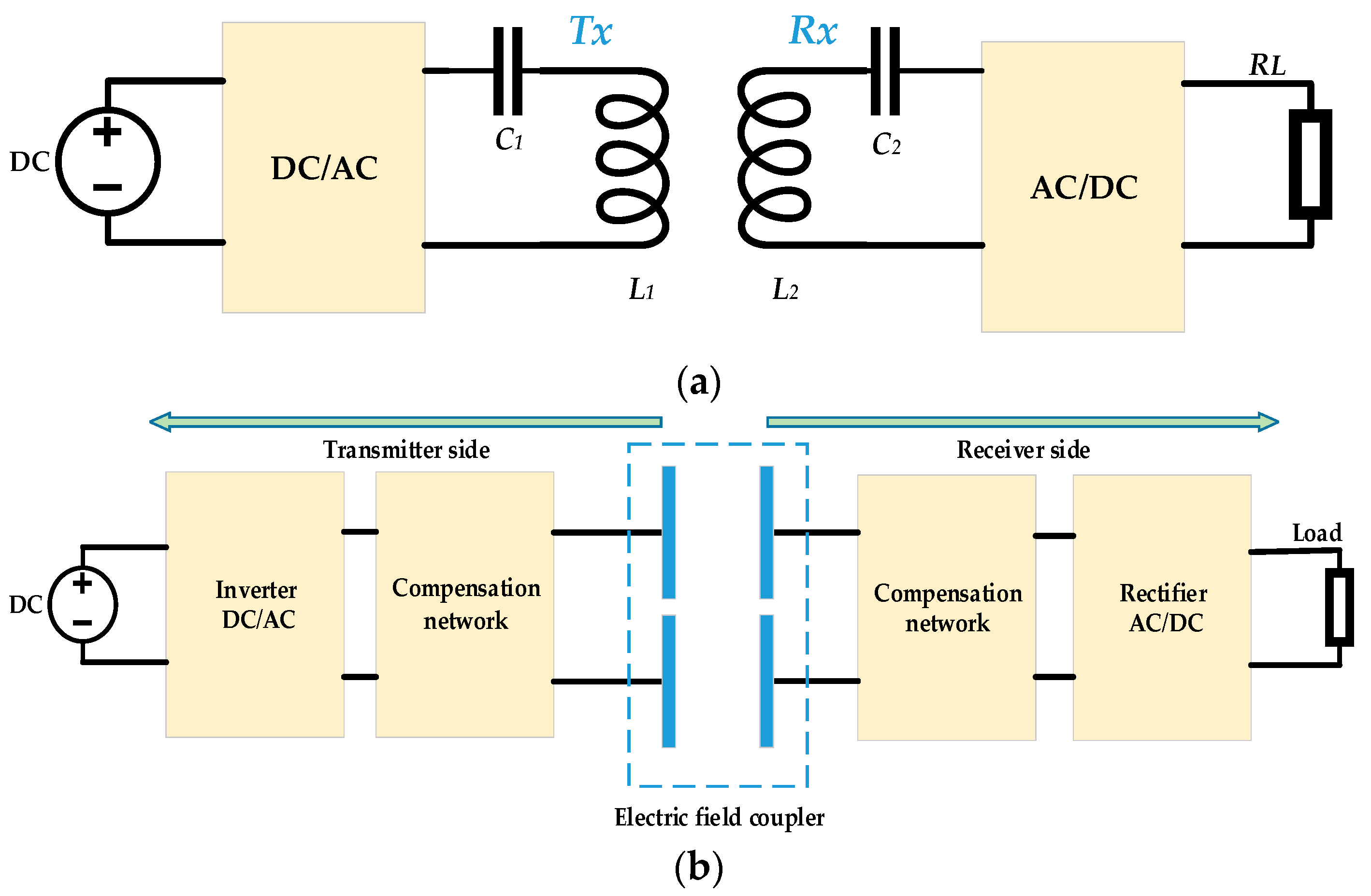
Figure 2.
WPT classifications and major research areas.

Figure 3.
Classifications of the compensation topology.
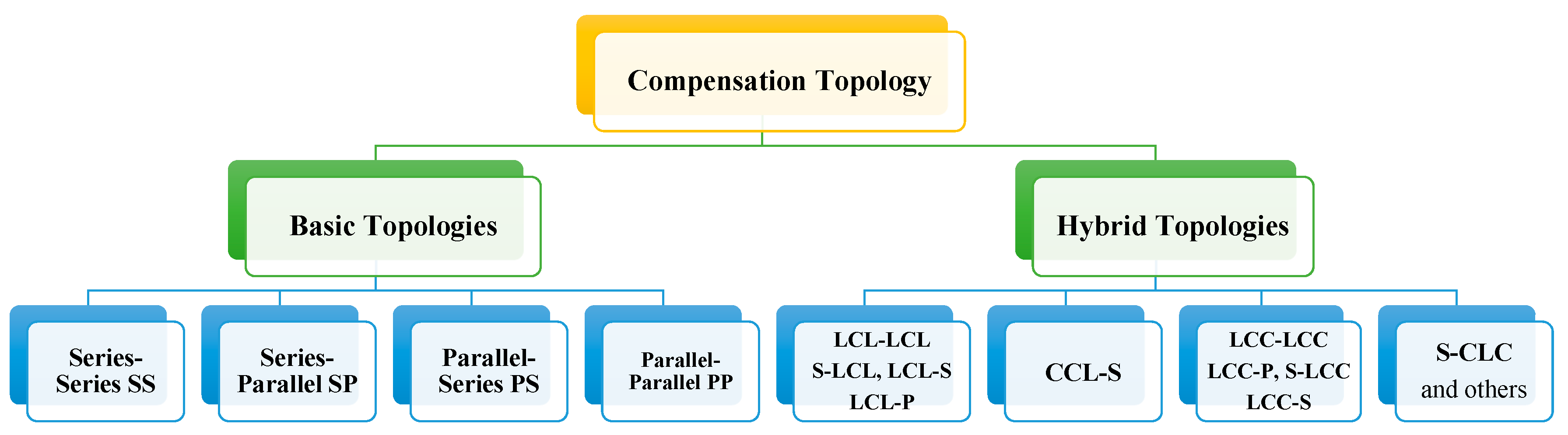
Figure 4.
The basic topologies: (a) Series-Series (SS); (b) Series-Parallel (SP); (c) Parallel-Series (PS); (d) Parallel-Parallel (PP).
Figure 4.
The basic topologies: (a) Series-Series (SS); (b) Series-Parallel (SP); (c) Parallel-Series (PS); (d) Parallel-Parallel (PP).

Figure 5.
Hybrid compensation topologies: (a) S-CLC; (b) S-LCL; (c) CCL-S; (d) LCL-S; (e) LCC-LCC; (f) LCL-LCL; (g) LCC-P; (h) LCL-P; (i) LCC-S; (j) S-LCL; (k) Double-Sided LCC.
Figure 5.
Hybrid compensation topologies: (a) S-CLC; (b) S-LCL; (c) CCL-S; (d) LCL-S; (e) LCC-LCC; (f) LCL-LCL; (g) LCC-P; (h) LCL-P; (i) LCC-S; (j) S-LCL; (k) Double-Sided LCC.


Figure 6.
Classifications of resonator structure.
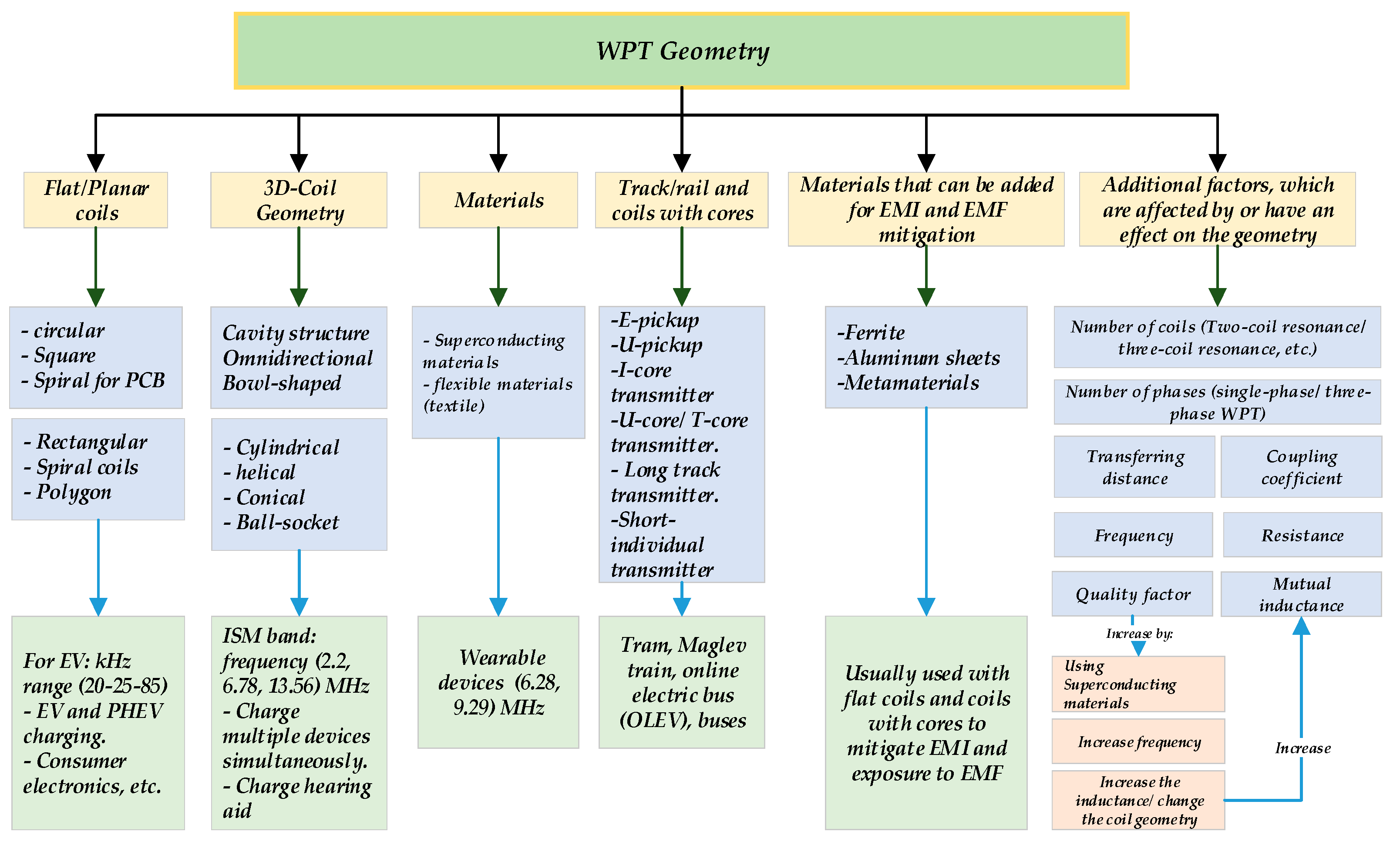
Figure 7.
MCR WPT structure based on the number of the coils: (a) Four-coil MCR WPT; (b) Three-coil MCR WPT.
Figure 7.
MCR WPT structure based on the number of the coils: (a) Four-coil MCR WPT; (b) Three-coil MCR WPT.

Figure 8.
Equivalent circuit of the real inductor.

Figure 9.
Skin effect (done by ANSYS Electronics 19.0.0; Canonsburg, PA, USA; 2018): (a) 60 Hz; (b) 20 kHz; (c) 85 kHz.
Figure 9.
Skin effect (done by ANSYS Electronics 19.0.0; Canonsburg, PA, USA; 2018): (a) 60 Hz; (b) 20 kHz; (c) 85 kHz.


Figure 10.
Efficiency at the resonant frequency (500 kHz) for two spherical structures. (a,b) k = 0.089; (c,d) k = 0.54.
Figure 10.
Efficiency at the resonant frequency (500 kHz) for two spherical structures. (a,b) k = 0.089; (c,d) k = 0.54.
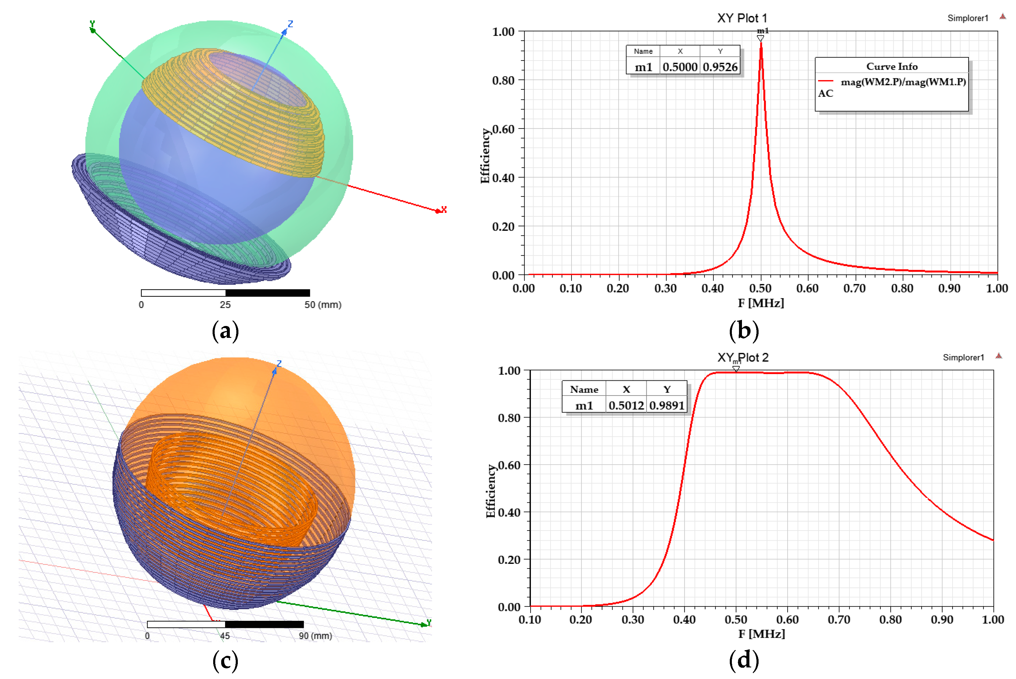
Figure 11.
Types of misalignments: (a) Vertical variation; (b) Planar; (c) Angular; (d) Lateral (horizontal); (e) Planar and horizontal; (f) Angular horizontal.
Figure 11.
Types of misalignments: (a) Vertical variation; (b) Planar; (c) Angular; (d) Lateral (horizontal); (e) Planar and horizontal; (f) Angular horizontal.

Figure 12.
EMF mitigation methods.
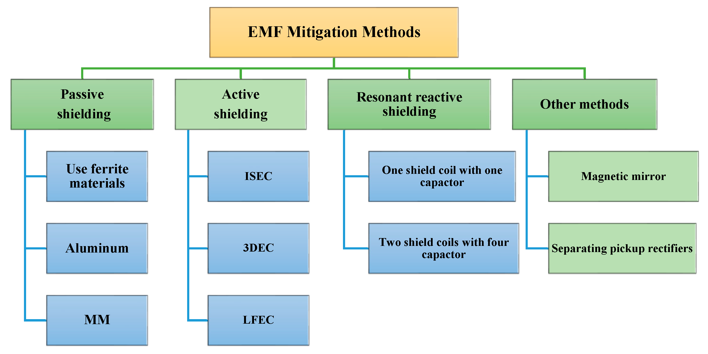
Figure 13.
WPT applications.

Figure 14.
Joint-WPT: (a) Displacement angle (0°–85°); (b) An example of winding Tx and Rx coils; (c) Spherical model (0°–45°).
Figure 14.
Joint-WPT: (a) Displacement angle (0°–85°); (b) An example of winding Tx and Rx coils; (c) Spherical model (0°–45°).
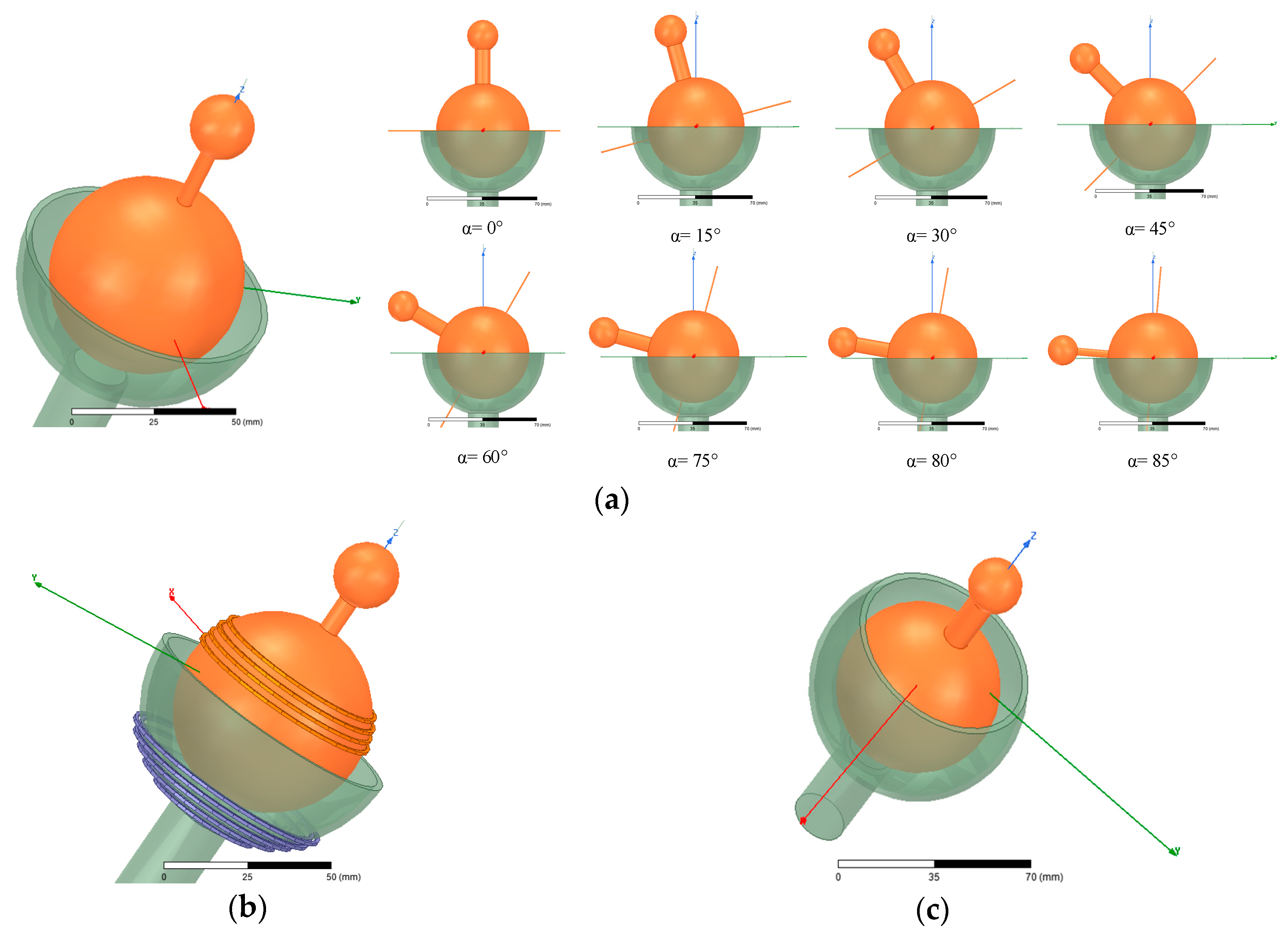
Figure 15.
Schematic represents the design process of a WPT system.

Figure 16.
Joint WPT in the y-z plane with several variables to parameterize the coils.

Figure 17.
Flowchart represents the algorithm design of the joint WPT.

Figure 18.
Two case studies: (a) Hemisphere winding at 0°; (b) Hemisphere winding at 90°; (c) Optimized design at 0°; (d) Optimized design at 90°.
Figure 18.
Two case studies: (a) Hemisphere winding at 0°; (b) Hemisphere winding at 90°; (c) Optimized design at 0°; (d) Optimized design at 90°.
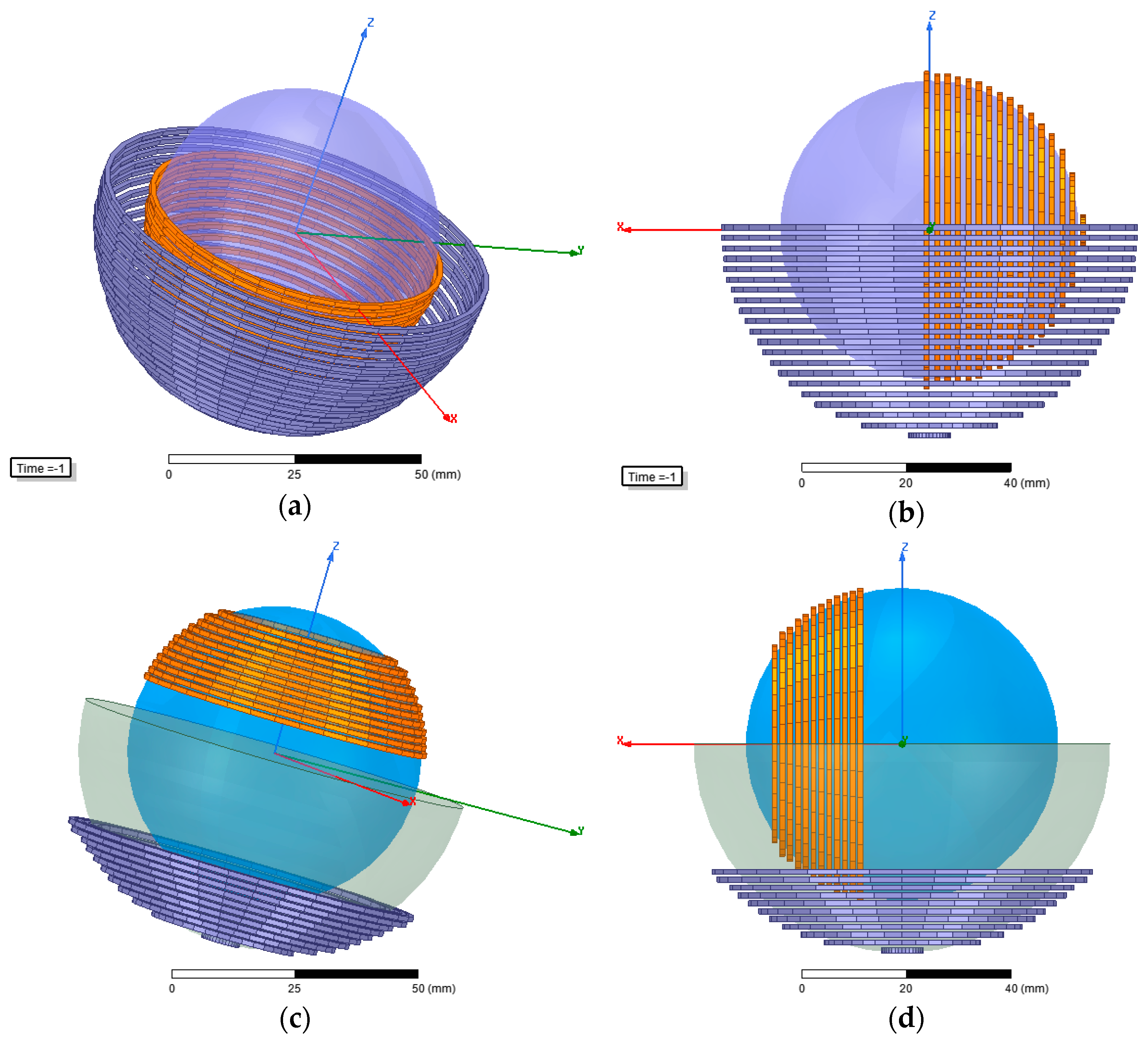
Figure 19.
The mutual inductance and coupling coefficient: (a) Hemisphere winding; (b) Optimized design.
Figure 19.
The mutual inductance and coupling coefficient: (a) Hemisphere winding; (b) Optimized design.

Figure 20.
WPT efficiency: (a) Hemisphere winding; (b) Optimized design.

Figure 21.
The magnetic field density (B vector/cross section): (a) Optimized design; (b) Hemisphere winding.
Figure 21.
The magnetic field density (B vector/cross section): (a) Optimized design; (b) Hemisphere winding.

Figure 22.
Experimental setup: (a) Circuits; (b) Hemisphere windings; (c) Optimized design at α = 0°; (d) Optimized design at α = 90°.
Figure 22.
Experimental setup: (a) Circuits; (b) Hemisphere windings; (c) Optimized design at α = 0°; (d) Optimized design at α = 90°.
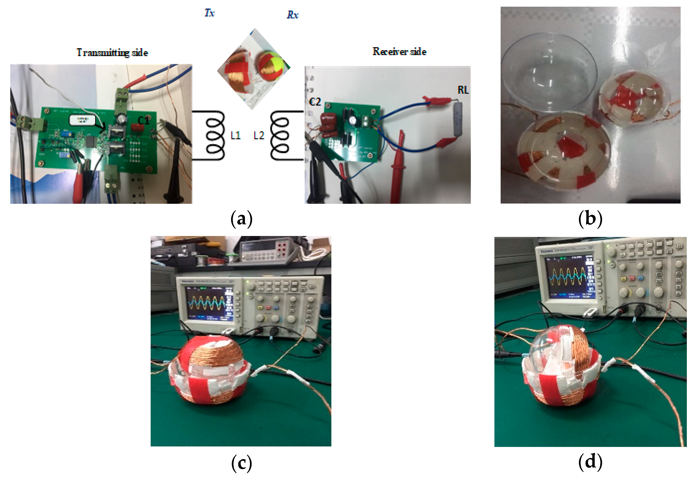
Figure 23.
(a) Pulse-width modulation (PWM) signal; (b) Input/output voltages for the hemisphere case; (c) Input/output voltages for the optimized model.
Figure 23.
(a) Pulse-width modulation (PWM) signal; (b) Input/output voltages for the hemisphere case; (c) Input/output voltages for the optimized model.

Figure 24.
Input (blue) and output (orange) coil-to-coil voltages for the hemisphere winding.

Figure 25.
Input (blue) and output (orange) coil-to-coil voltages for the optimized model.
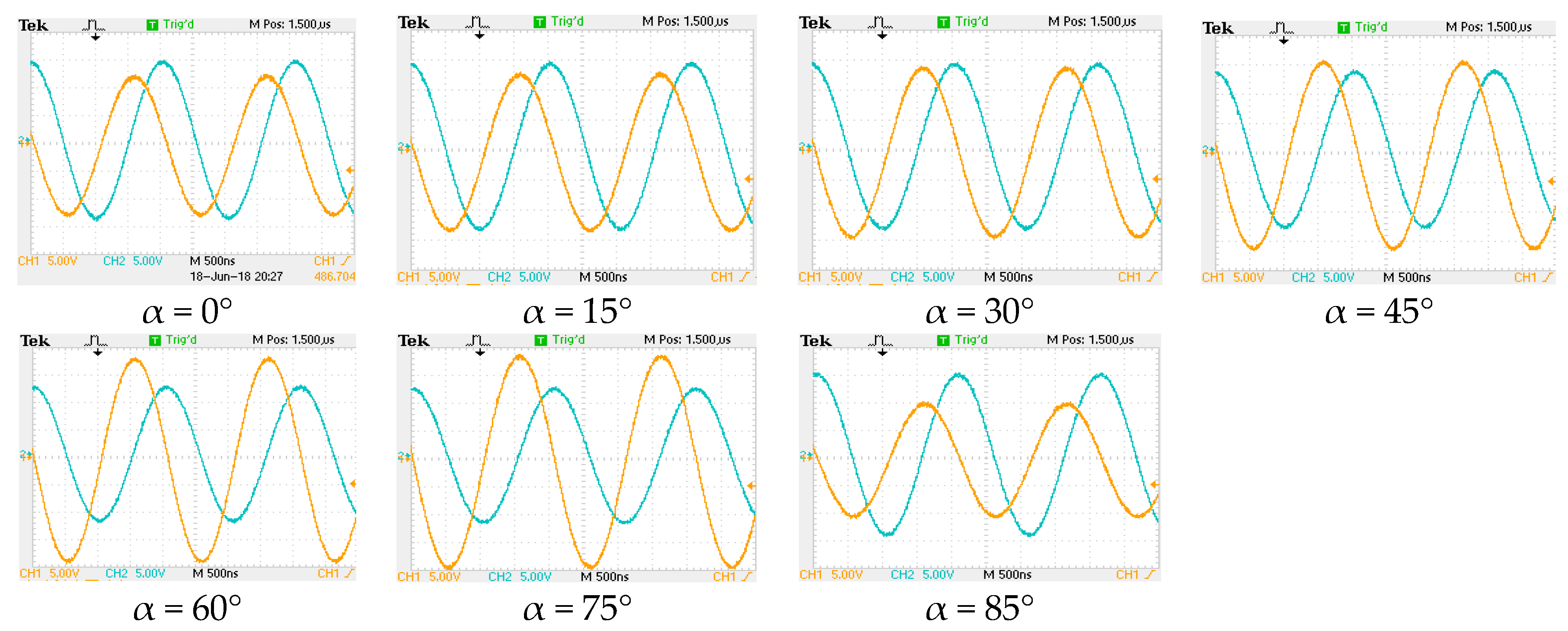
Figure 26.
Influencing factors in order to get an optimal WPT.
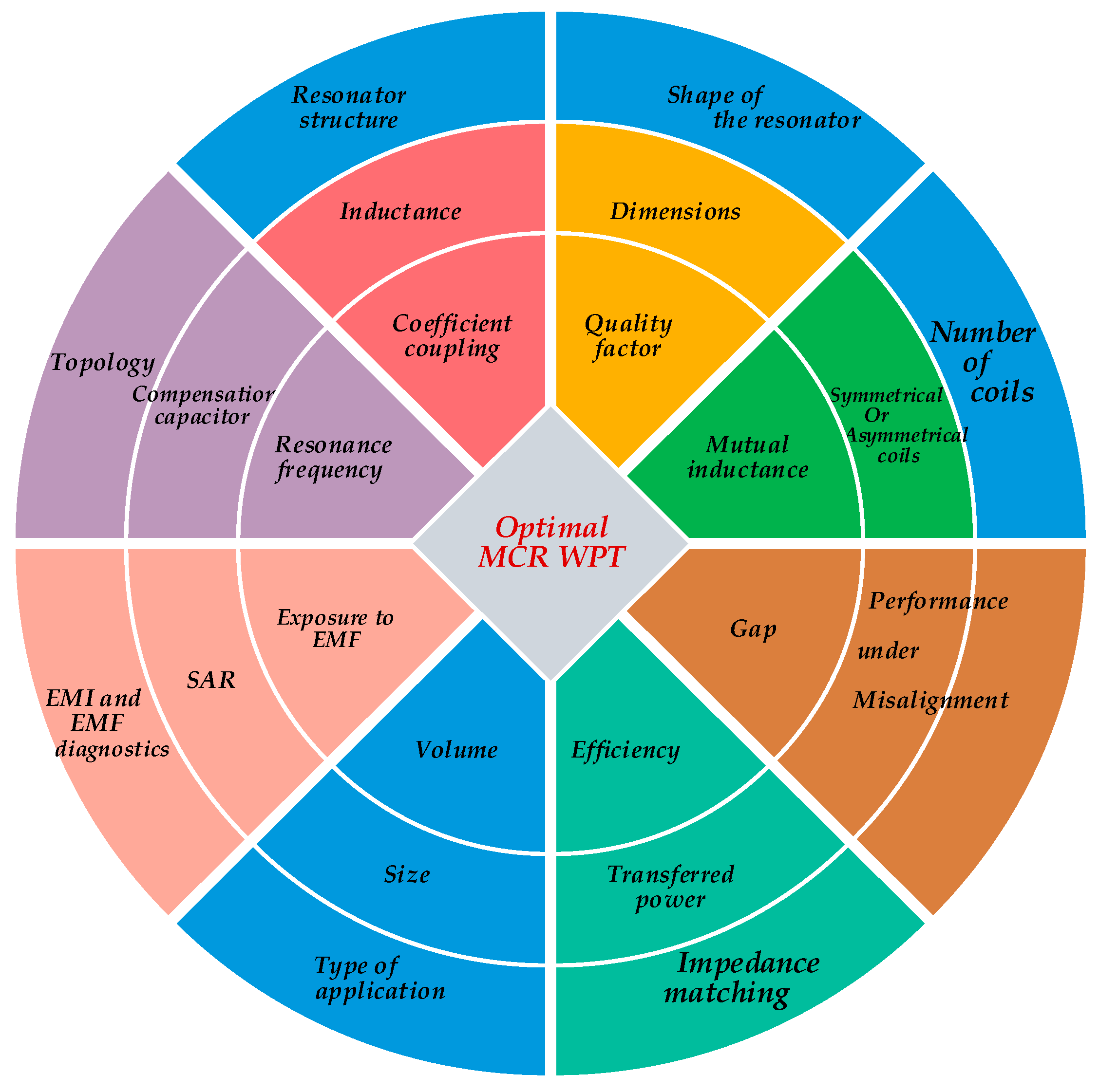

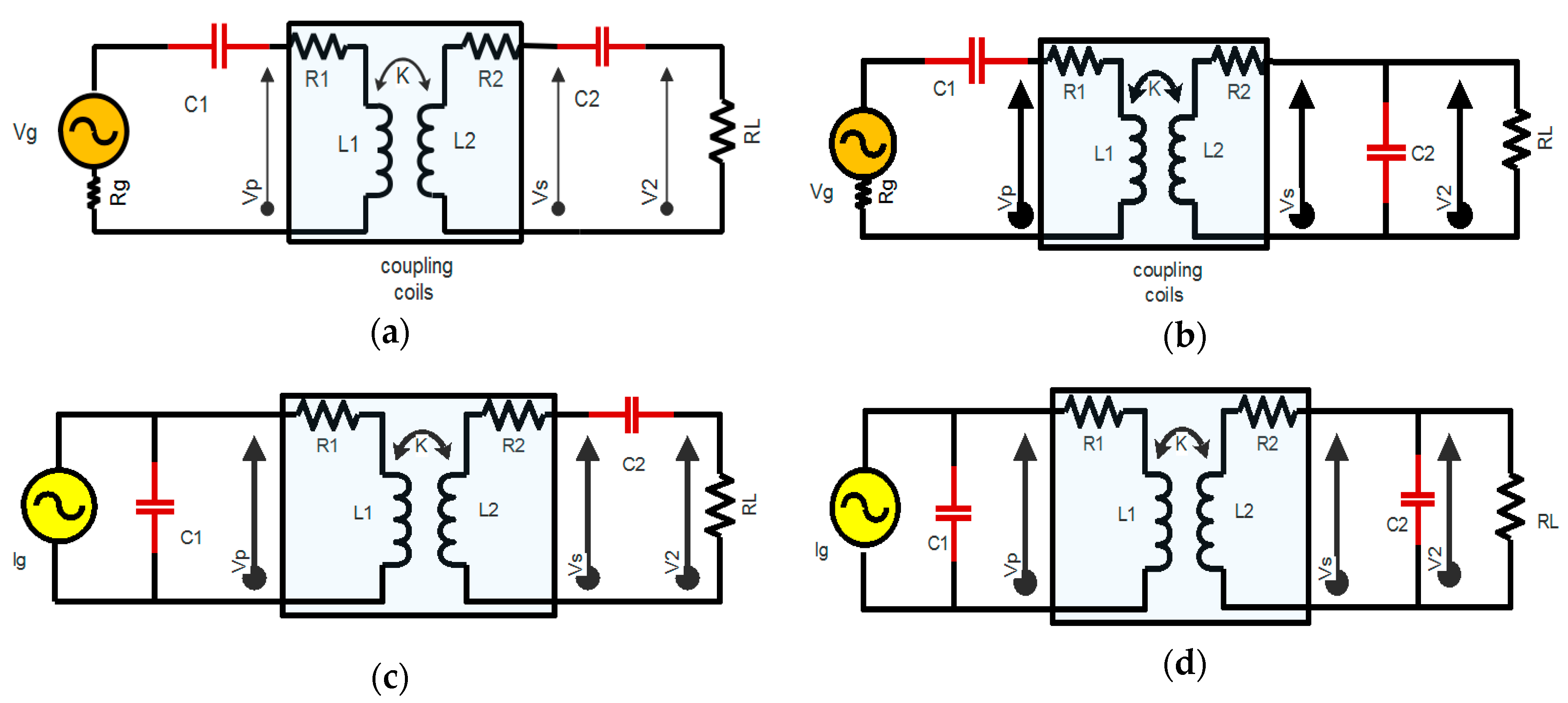
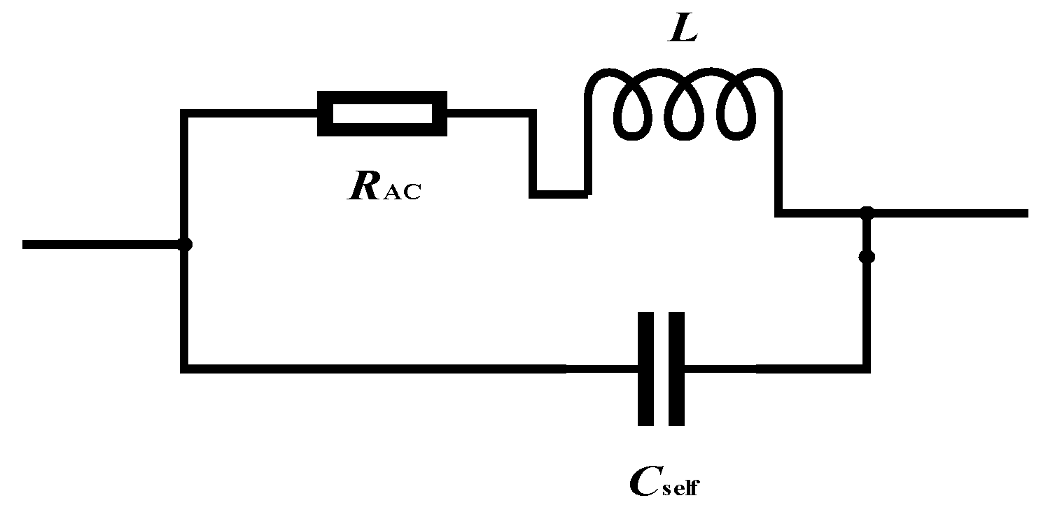
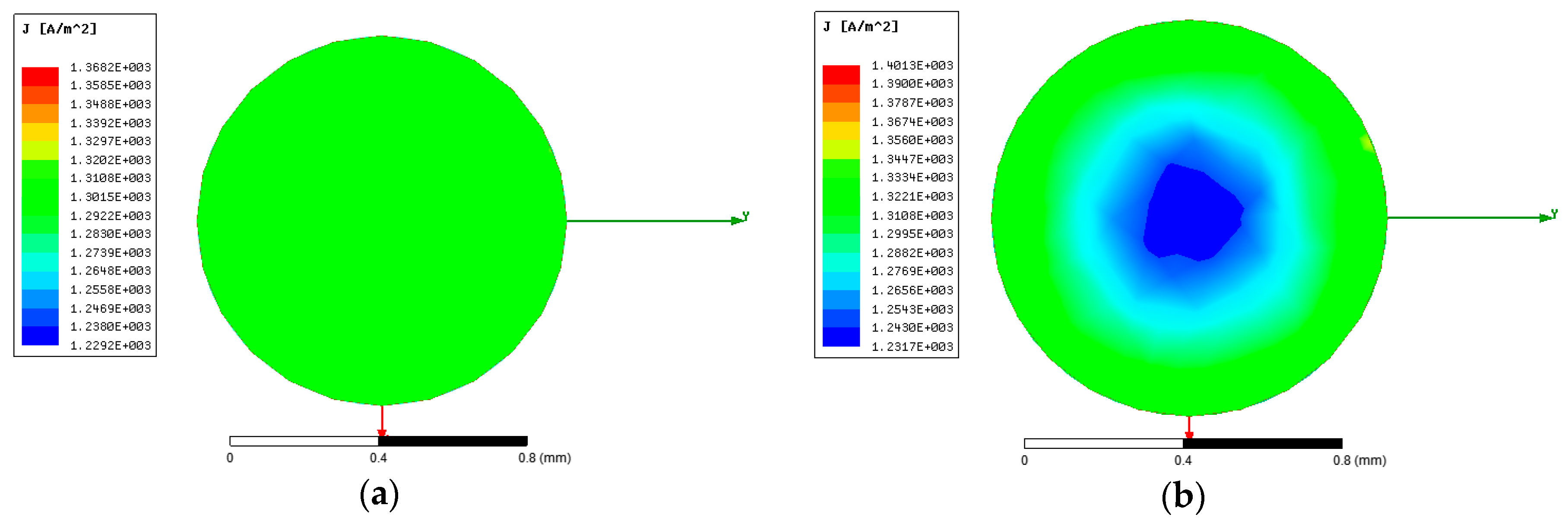
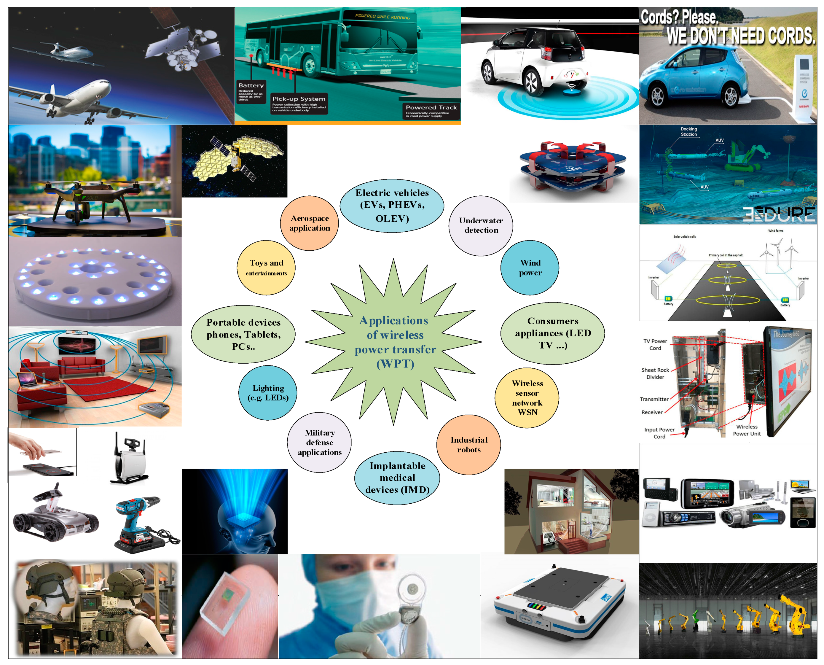
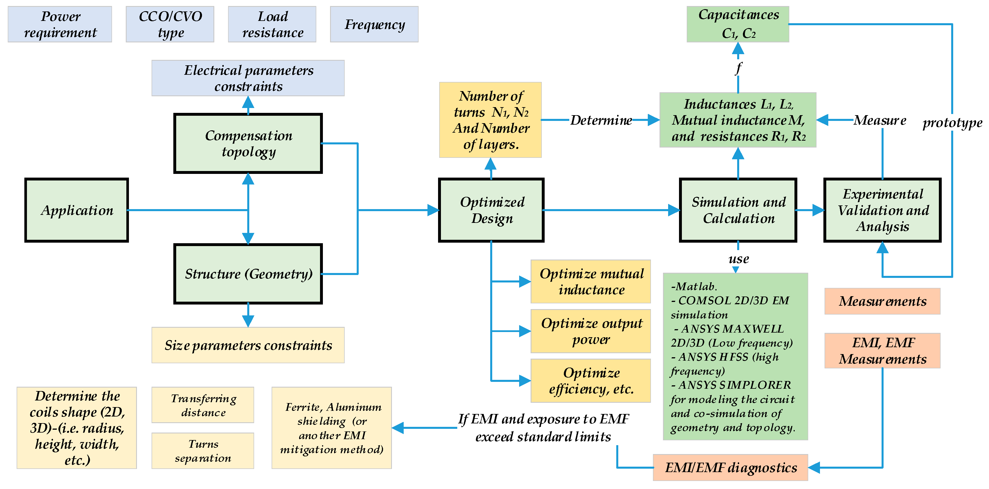
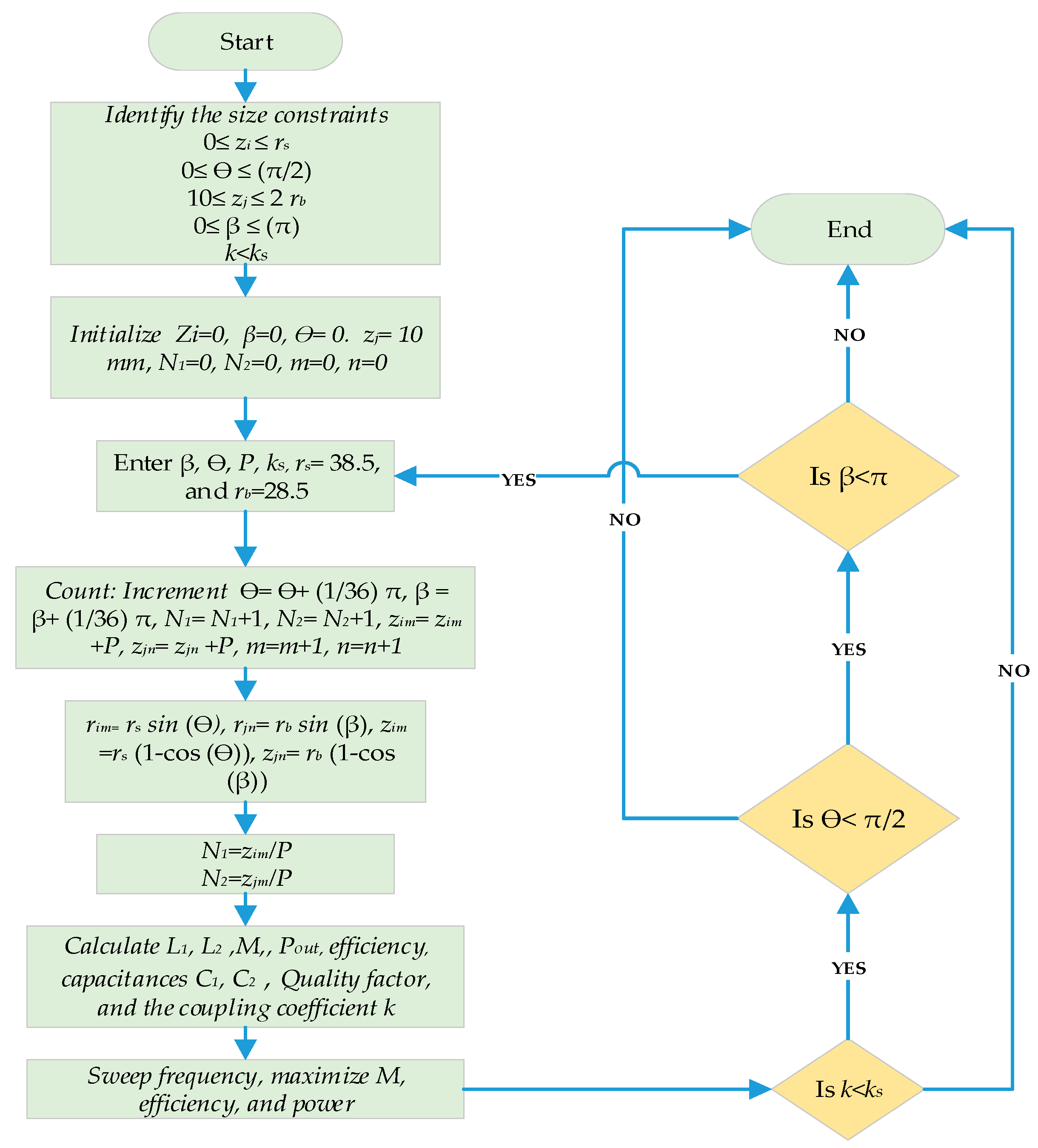
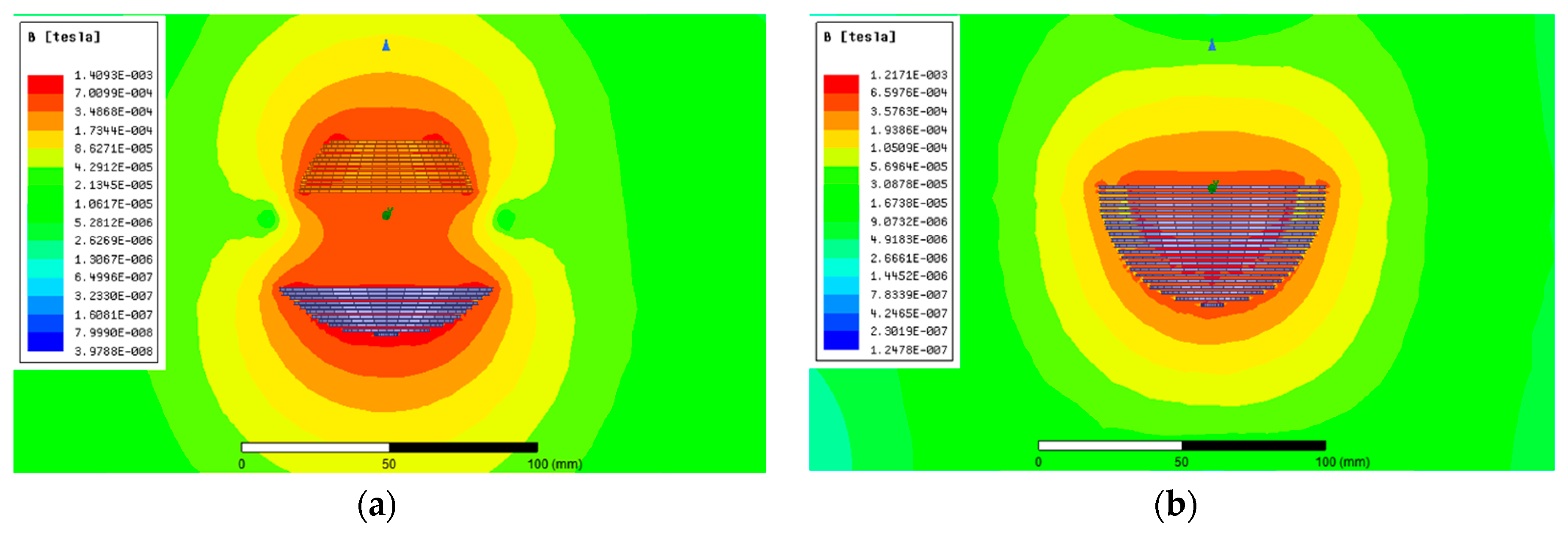
Table 1.
Review of different WPT systems based on topology and application type (such as electric vehicles, or EVs). EMI: electromagnetic field interference.
Table 1.
Review of different WPT systems based on topology and application type (such as electric vehicles, or EVs). EMI: electromagnetic field interference.
| Reference and Topology | f0/k/RL (kHz, Ω) | Pout, Vout | Efficiency | Resonators | Note | |||
|---|---|---|---|---|---|---|---|---|
| N1 Turn N2 Turn | D1 mm Length, Diameter mm | D2 mm width, Diameter mm | Gap mm | |||||
| [14] SS/LCC-LCC | f0 = 85 k = 0.135 RL = 2, 3, 5 | 1 kW 50 V | 95% for SS, and 93% for LCC | 10 8 | 500 diameter | 400 diameter | 200 | Based on EMI, LCC-LCC topology is considered more robust to EMI exposure. |
| [89] SS/LCC-LCC | f0 = 79 | 7.7 kW max. 270~405 V | For LCC: 96% | - | 800 | 600 | 200 | The LCC-LCC topology has higher efficiency when the mutual inductance is at minimum. |
| [101] SS/LCL-LCL | f0 = 85 k = 0.1 RL = 10 | 3.3 kW | 93.1% for SS, 89.5% for LCC | 20 × 3 layers 17 × 2 layers | 550 × 400 mm2 | 240 × 240 mm2 | 100 | Compared to SS topology, the LCL-LCL type has a high power factor. |
| [98] LCC-LCC | f0 = 79 k = 0.18~0.32 RL = 10~200 | 7.5 kW 450 V | 96% | 1 | 800 | 600 | 200 | Resonant frequency f0 is independent of the coupling coefficient and load conditions. |
| [99] LCC-LCC | f0 = 95 k = 0.14–0.30 | 5.6 kW 300~450 V | 95.36% | - | 600 | 600 | 150 | The extra integration-induced couplings give more space for magnetic cores. |
| 200 | 200 | |||||||
| [87] LCC-LCC | f0 = 85 k = 0.153 RL = 49.95 | 3.3 kW 405.7 V | 92.6% | 18 16 | 600 | 300 | 150 | Energy storage has no relation to topology type, but only with transferred power level and coupling coefficient. |
| [97] LCC-LCC | f0 = 85 k = 0.1877 | 3 kW 300 V | 95.5% | - | 600 × 450 × 4 mm3 | 400 × 300 × 4 mm3 | 150 | The compensated resonator design helps to eliminate or reduce the extra-coupling effects to a tiny level. |
| 640 × 496 × 8 mm3 | 480 × 352 × 8 mm3 | |||||||
| 711.2 × 558.8 × 2 mm3 | 508 × 406 × 2 mm3 | |||||||
Table 2.
Review of WPT systems that are used in dynamic charging for EVs and plug-in hybrid electric vehicles (PHEVs).
Table 2.
Review of WPT systems that are used in dynamic charging for EVs and plug-in hybrid electric vehicles (PHEVs).
| Reference and Topology | f0/k/RL (kHz, Ω) | Pout, Vout | Efficiency | Coils’ Dimensions and Number of Turns | Gap mm | Note |
|---|---|---|---|---|---|---|
| [96] LCL-S LCC-S | f0 = 140 k = 0.18–0.32 | Nominal power: 1 kW 80~90 V | Similar: LCC and LCL: 93% | Coil radius is 163 mm | 100 | The topology gives more robust power transfer character against the variation of k. |
| [100] Double-sided LCC | f0 = 85 k = 0.13 | 1.4 kW 150 V | 89.78% | 9 turns for each transmitter, Tx coil 6× (388 mm×400 mm), and for Rx: 485 mm×400 mm | 150 | This paper presented a continuous dynamic WPT system, which reduces the power pulsations. |
| [102] LCL | f0 = 85 k = 3.7–5.4% | 5 kW | - | The secondary: 0.35 m × 0.7 m N87 ferrite material (each 93 mm × 28 mm × 16 mm). | 240 | The system is designed to supply power along the whole length of the track by activating only one primary pad. |
| [103] SS | f0 = 85 k = 0.4 | 20 kW | 80% | Transmitter dimensions are 10 cm × 75 cm, number of turns: nine Receiver: 25 cm × 20 cm, number of turns: 12. | 100 | Downscale prototype operating at 85 kHz ± 2.5 kHz. |
| [104] SP | f0 = 23 RL = 2 | 2 kW | - | Coils diameter: 330 mm. Turns: seven turns for transmitter coil and five turns for receiver coil. | 100 | This paper presented technical aspects of in-motion WPTs for charging EVs and PHEVs. |
| [105] SS | f0 = 85 | - | 97.6% pads length ratio is 1:1 | Coil external width: 58 mm Coil inner width 38 Wire diameter 5 mm Number of turns: 8 turns. | 200 | Investigated the pad shape: influence of the variation of the ratio between Tx and Rx lengths with respect to the behavior of the coupling. |
Table 3.
Research works related to defected ground structure (DGS).
| WPT System | Resonator Parameters | f0/k | Efficiency | Note | |||||
|---|---|---|---|---|---|---|---|---|---|
| Resonator Structure | Size of the Coils/Number of the Coils | N1/N2 Ratio | D1 mm | D2 mm | Gap mm | ||||
| [113] | H-shaped DGS | Symmetrical, two-coil resonance structure | 1 | 20 | 20 | 13 | 300 kHz/k = 0.025 | 68%/73% | Semi H-shaped DGS resonator is more robust to the coaxial orientation misalignment. |
| Semi-H-shaped DGS | 21 | 21 | 25 | ||||||
| [114] | Spiral-strips DGS | Symmetrical | 1 | 50 × 50 mm2 | 50 × 50 mm2 | 50 | 50 MHz | 84%/78% | Spiral-strips DGS provides a better quality factor other than H-shaped or semi-H-shaped DGS. |
| Asymmetrical | 50 × 50 mm2 | 30 × 30 mm2 | 40 | ||||||
Table 4.
Research work related to three-dimensional (3D) structure.
| WPT System | Resonators | f0, RLPout, Vout, Efficiency % | Note | |||
|---|---|---|---|---|---|---|
| Resonator Structure | Size of the Coils/Number of Coils | Coils’ Dimensions and Number of Turns | Gap | |||
| [80] | Structures: cylindrical for Tx, Rx1, and planar rectangular for Rx2. | Asymmetrical/four-coil resonator structure | The diameter of Tx is 350 mm, the thickness is 0.35 mm, and the width is 29 mm besides a one-turn driving coil. The radius of Rx1: 80 mm, the height: 50 mm, besides a seven-turn coil that was used as the output coil. The area of Rx2 is 20.5 × 20 mm2, and the thickness is 0.35 mm. | 150 mm Tx1 | 7 MHz LED loads 80% | Tx is simply printed on the internal or external cover, or inserted in the clothes. |
| 200 mm Tx2 | ||||||
| [132] | Helical coils | Symmetrical/three-coil resonator structure | The radius is 0.325 m, the pitch is 0.05 m, and the number of turns is N = 5, d12 = 6 m | 2–4 m | 10 MHz 90% | Compared with a single-transmitter WPT system, a higher power transfer efficiency (PTE) was achieved stably for the angular aligned and the angular misaligned. |
| [29] | 3D structure/Bowl-shaped transmitter coil and spiral helical receiver coils | Asymmetrical/three-coil resonator structure | The Tx bowl-shaped, which is a combination of both a spiral coil (s) and a conical-shaped coil (c) with a big diameter of 58 mm, a thickness of 9.1 mm, and turns: NS = Nc = 7 turns. | Within 3D cavity | 6.78 MHz 2.5 to 4.3 V 60% | The proposed system can uniformly charge a pouch-type LIB of a hearing aid in spite of its position or arrangement. |
| The volume of the receiver coils Rx (spiral s1+ helical h) is 10.5 × 6.5 × 2.46 mm3 with Ns1 = Nh = 8 turns | ||||||
| 3D structure: WPT systems operating at higher frequencies: | ||||||
| [131] | 3D structure/Helical coils | Symmetrical/system with Relay resonator | Symmetrical relay resonator with multi load transfer and number of turns is 12 | - | 193 MHz 0.1~2.0 Ω Several dozen watts of power, 30~40% | The WPT system transfers the same power to multiple loads over a range of distances. |
| [136] | The Tx is a cavity resonator and the Rx is a square coil | Asymmetrical/multi-coil structure | The dimensions of the cavity resonator are a = 1.52 m, b = 1.42 m, and d = 1.83 m. Rx square coil has one turn 7.62 cm. (multi receivers) | 91 cm | 191.65 MHz 50-Ω 8-W LED 50% | The system is able to deliver power to many devices simultaneously, such as LEDs and toys in a box. |
| [138] | 3D structure/Cylindrical cavity resonator | Asymmetrical/two-coil structure | The radius of the Tx coil is 30 cm, and the height is 25.4 cm; the volume of the cavity is 0.072 m3. The radius of Rx is 2.5 mm, and the volume of the receiver coil is 13.75 mm3. | 10 cm | 375.32 MHz 50 Ω 33% | PTE of the optimal impedance-matching (IM) system can achieve 33.88%, which is four times the 7.68% that can be achieved without an optimal IM system. |
Table 5.
Research work related to flat structures for low-power applications.
| WPT System | Resonator Parameters | f0/k/RL | Pout, Efficiency % | Note | |||
|---|---|---|---|---|---|---|---|
| Resonator Structure | Coils/Number of the Coils | Coils’ Dimensions and Number of Turns | Gap | ||||
| [116] | Flat structure/Circular coils (44-mm inner diameter) | Symmetrical/three-coil resonance structure | Two 76-mm diameter circular coils and a source coil with 36-mm diameter. | 62 mm | 684 kHz 20 Ω | 12.9 W 43% At 40 mm | The maximum efficiency of the three-coil system shows a significant advantage over that of the two-coil system. |
| [117] | Flat structure/Circular spiral coils | Asymmetrical/four-coil resonance structure | Six turns for each coil. Outer diameter for Tx is 590 mm; for Rx, it is 280 mm, and the drive loop diameter is 280 mm | 700 m | 7.65 MHz k = 0.1376 | 12 W Laptop 50% | Presented a WPT that maximizes the quality factor of the coils; by proper loading of the drive and load loops, efficiency will be better. |
| [122] | Double-layer printed spiral coil PSC (square spiral coil) | Symmetrical/four-coil resonance structure | Double-layered for each layer: 3.875 turns. Width: 288 mm, Substrate: 300 mm × 300 mm | 500 mm | 4.03 MHz | 150 W 50% | The printed spiral coil (PSC) has high precision, high stability, easy to design, and manufacture. |
Table 6.
Research work related to coil with cores structure.
| WPT System | Resonators | f0/k/RL | Pout, Vout, Efficiency % | Note | |||
|---|---|---|---|---|---|---|---|
| Resonator Structure | Size of the Coils/Number of Coils | Coils’ Dimensions and Number of Turns | Gap | ||||
| [64] | Coil with a core/Dipoles with cores | Symmetrical/two-coil resonance structure | Number of turns for Rx: 22. Number of turns for Tx: 86. The length of the core is 3 m, and the length of the coil is 1 m. | 3 m | 20 kHz k: (0.68%,0.39%, 0.26%) 40 Ω | 1403 W 29% | Coils with ferrite cores will minimize parasitic effects. The optimum-stepped core structure can reduce the core loss. |
| 4 m | 471 W 16% | ||||||
| 5 m | 209 W 8% | ||||||
| For roadway-powered moving electric vehicles (high power) | |||||||
| [146] | Coil with a core/Resonator with EE, UU core-type | Asymmetrical/multi-coil structure | Power line modules in addition to UU, EE cores. Pick up coils for EE: five coils total, center: 64 turns, left and right: 28 turns each. | 26 cm | 20 kHz | 100 kW 620 V 80% | The implementation cost of the power receiver unit/kW was about $89/kW. |
Table 7.
Domino resonator systems.
| WPT System | Resonator parameters | f0/RL | Pout, Efficiency % | Note | |
|---|---|---|---|---|---|
| Resonator Structure | Coils’ Dimensions and Number of Turns | ||||
| [151,152] | Symmetrical/circular coils/domino structure/ | The WPT has eight resonators, which have a radius of path r of 300/235 mm for three-resonator and four-resonator systems, respectively. The number of turns is 11. | 520 kHz (11.57~16.94) Ω | 14 W, 70.68~83% | The optimized operating frequency of this system is not the resonant frequency of the resonators. |
Table 8.
Research work on circular structures.
| Case | 1 | 2 | 3 | 4 | 6 |
|---|---|---|---|---|---|
| A/S/iC | A/2C | S/2C | S/2C | A/2C | S/2C |
| Topology | SS | LCL-S LCC-S | SP | LCC-LCC | SS |
| Size D1/D2 mm | 500/400 | 226/226 | 500/500 | 600/300 | 220/220 |
| Gap mm | 200 | 100 | 200 | 150 | 240 |
| Frequency | 85 kHz | 140 kHz | 20 kHz | 85 kHz | 200 kHz |
| Efficiency | 95% | 93% | 93% | 92.6% | 85% |
Note: A: asymmetrical system; S: symmetrical system; C: coil; i: number of coils.
Table 9.
Research work on rectangular structures.
| Case | 1 | 2 | 4 |
|---|---|---|---|
| A/S | S | A | S |
| Topology | LCC-LCC | LCC-LCC | S-SP |
| Size mm2 | 800 × 600 | 600 × 450 400 × 300 | 500 × 600 |
| Gap mm | 200 | 150 | 100 |
| Frequency kHz | 79 | 85 | 40 |
| Efficiency | 96% | 95.5% | 95.2% |
Table 10.
The inductance of different coreless loops.
| Resonator Type | Inductance | Comments |
|---|---|---|
| Straight conductor | l: Length, a: radius of the conductor. | |
| Square loop | Where N: The number of turns. | μr: Relative permeability. |
| Rectangular loop | 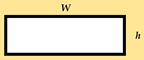 | |
| Circular | R: radius |  |
| Equilateral triangle |  | |
| Pancake coil (flat spiral coil) | where: W: the wire diameter. S: the separation between two turns. | 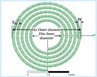 |
| Square spiral coil | where R = P/q q: thickness, P: the separation between turns. | 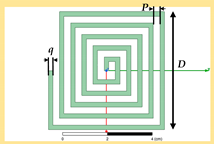 |
| On-chip inductor spiral loops L- (nH) [124] | where: xi—Factors from (layout depending, it is given in Table 11) | 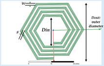 φ—Fill factor |
Table 11.
Layout dependent factors.
| Layout | x1 | x2 | x3 | x4 |
|---|---|---|---|---|
| Square | 1.27 | 2.07 | 0.18 | 0.13 |
| Hexagonal | 1.09 | 2.23 | 0 | 0.17 |
| Octagonal | 1.07 | 2.29 | 0 | 0.19 |
| Circular | 1 | 2.46 | 0 | 0.2 |
Table 12.
Misalignment types: a review. SCMR: strongly coupled magnetic resonance. HSCMR: hybrid SCMR. CSCMR: conformal SCMR.
Table 12.
Misalignment types: a review. SCMR: strongly coupled magnetic resonance. HSCMR: hybrid SCMR. CSCMR: conformal SCMR.
| Case | The Resonator Structure | Misalignment Type | The Effect of Misalignments | Comments |
|---|---|---|---|---|
| [173] | Circular spiral coil | Lateral/Angular | The values of output voltage decrease with the misalignment. | According to the test, even if the lateral and angular misalignments happen. The efficiency at a 5 cm distance is up to 50%. |
| [161] | Circular | Lateral/Angular azimuth/Angular elevation | The proposed structures: 3D SCMR, HSCMR, and CSCMR are less sensitive to the misalignments than the standard SCMR system. | The system achieves an efficiency of 40% for the entire range of 360° in case of the angular misalignment. |
| [1] | Helical | Lateral/Angular general (angular horizontal) | M = x (Δ, α). N2: M is the mutual inductance, which increases linearly depending on the square of the coil turns. | x (Δ, α) is a variable coefficient that depends on the lateral misalignment Δ, and the angular misalignment α. The average value of the slope is (0−10 cm, 0~50°). |
| [99] | Double D (DD) bipolar pads | Horizontal | The efficiency is higher than 90%, even at a large misalignment in the x-direction. | For EV application, the x-misalignment is door-to-door, and the y-misalignment is front to rear. |
| [95] | UU type | Horizontal/Vertical | The self-inductance of the pads changes slowly with the misalignment of the coils, but the mutual inductance changes fast. | The current-fed compensation topology is a practical solution for WPT. |
| [132] | Helical coils | Angular | Compared to the single-transmitter WPT system, the proposed system gives a higher power transfer efficiency during the angular aligned and in case of the angular misaligned. | The paper proposed a multiple-transmitter WPT, which provides a power transfer diversity. |
| [113] | H-shaped DGS and semi-H-shaped | Horizontal shift/Coaxial orientation | Compared to H-shaped DGS, the semi-H-shaped DGS is more robust to misalignments. | These features boost the usage of the semi-H-shaped DGS in WPT applications. |
| [117] | Circular spiral coil | Angular | The case of a fixed frequency undergoes the same trend of process from the over coupled to critically coupled, and then under coupled system. | The receiver unit is placed on the axis at a fixed transferring distance of 50 cm. |
| [110] | Rectangular | Forward direction | Compared with SP-compensated WPT, the S/SP-compensated WPT is more robust to the misalignment. | The range of the output voltage of the SP-compensated WPT is almost double that of the S/SP-compensated WPT, |
Table 13.
Comprehensive review of WPT-related standards and guidelines. EMF: electromagnetic field, EU: European Union, ICPT: inductive coupled power transfer, USA: United States.
Table 13.
Comprehensive review of WPT-related standards and guidelines. EMF: electromagnetic field, EU: European Union, ICPT: inductive coupled power transfer, USA: United States.
| Standards | Substandard | Country | Frequency/Power | Application/Comments |
|---|---|---|---|---|
| Federal Communications Commission (FCC) | KDB 680106 Part 15B and part 18 | USA | Above 9 kHz are considered intentional radiators. | Radio frequency (RF) exposure wireless charging apps (wireless chargers, inductive chargers, and wireless charging pads). |
| Society of Automotive Engineers (SAE) | SAE J2954/J2836/6™ J2847/6-J2931/6 | J2954™ EVs and PHEVs use 85 kHz band. | Wireless charging task force, specific use cases, and specific protocols. | |
| The International Special Committee on Radiofrequency Interference (CISPR) | CISPR SC-B | International | From 9 kHz upwards, CISPR 11 range is 150 kHz up to 1 GHz. | Household appliances, ignition systems, and fluorescent lamps. |
| CISPR 11:2015 | Power electronics in the industrial, scientific and medical frequency band (ISM band): RF equipment used in WPT. | |||
| International Electrotechnical Commission (IEC) | IEC 61980-1:2015, IEC 62827-2:2017, IEC PAS 63095-1:2017(E) | For IEC PAS 63095-1:2017(E) baseline power profiles are (≤5 W) and extended power profile is (≤15 W). |
| |
| International Organization for Standardization (ISO) | ISO PAS 19363, 2017-1-1, (ISO/NP 19363 under development) | Close synchronization with IEC 61980 and SAE J2954. |
| |
| International Commission on Non-Ionizing Radiation Protection (ICNIRP) | ICNIRP 1998 ICNIRP 2009 ICNIRP 2010 | EM Field: (1 Hz–100 kHz)/2010 (1 Hz–300 kHz) 1998. |
| |
| European Telecommunication Standards Institute (ETSI) | ETSI EN 303 417 V1.1.0 (2017-9). | EU | For WPT systems that use frequency other than RF beam, and it has investigated ranges: [19–21 kHz, 59–61 kHz, 79–90 kHz, 100–300 kHz, and 6765–6795 kHz]. | Harmonized standard, which covers the essential requirements of article 3.2 of Directive 2014/53/EU. |
| China Communication Standard Association (CCSA) | CCSA TC9 | China | Part1: General; part2: Tightly coupled (ICPT); and part3: Resonance wireless power transfer (MCR WPT). | EMF evaluation methods for WPT and EMC limit and measurements. |
| YD/T 2654-2013 | Requirements and test methods of EMC of WPT equipment. | |||
| Association of Radio Industries and Businesses (ARIB); Broadband Wireless Forum (BWF) | ARIB STD-T113 (2015) | Japan | 6.78 MHz-band MCR WPT for mobile, 400 kHz–band for CPT. EV/PHEV WPT spectrum: (42 kHz~48 kHz, 52 kHz~58 kHz, 79~90 kHz, and 140.91~148.5 kHz). Power: 3 kW and 7.7 kW. | Study for WPT spectrum for all the applications and technologies.
|
| BWF TR-02 Edition 1.0/2016 | 100 kHz, 100–500 kHz, and 6.78 MHz. |
| ||
| Telecommunication Technology Association (TTA) | TTAR-06.162 (19/11/2015) | Korea | For EV in 2011, OLEV (19 kHz~21 kHz and 59 kHz~61 kHz).Normal Power: 100 kW.Frequency: 13.56 MHz band is used for 3D glasses WPT. |
|
| Alliance for Wireless Power (A4WP) | A4WP standards | Established in 2012 (Samsung, Qualcomm and others) | 6.78 MHz for power transfer and 2.4 GHz for the control signals. |
|
| Wireless Power Consortium Qi (WPC) | Qi standards Version 1.0.Version 1.1. | Industry group, since 2008 | Range: 110 kHz–205 kHz.Low power in the range of (0–5) W. Medium power is up to 120 W. |
|
| Power Matters Alliance (PMA) | PMA standard | Founded by Procter, Gamble and Powermat in 2012. | 277 kHz–357 kHz and up to 5–10 W. |
|
| Additional standards for electromagnetic compatibility EMC, immunity tests and measurements: Radiated and conducted emissions—CISPR 11. Compliance testing of wireless power transfer products ASNI C63.30. Radiated EM immunity—ISO 11451-2:2015-06 (E). | ||||
Table 14.
Current and ongoing study frequency and power range for WPT in Japan and Korea. PCs: personal computers.
Table 14.
Current and ongoing study frequency and power range for WPT in Japan and Korea. PCs: personal computers.
| WPT System | Country | Frequency Range under Consideration | Power Range under Considerations | Application |
|---|---|---|---|---|
| Inductive coupling (IPT): low power | Already in Japan, Korea | Japan: 110 kHz–205 kHz. Korea:100 kHz–205 kHz. | - | Mobile devices, portable devices, consumer electronics (CE), and industrial fields. |
| Inductive coupling (IPT): high power | Japan | Japan: 20.05 kHz–38 kHz, 42 kHz–58 kHz, and 62 kHz–100 kHz. | Japan: Several watts up to 1.5 kW. | Home appliances operating with high power, and office equipment. |
| Magnetically coupling resonant (MCR WPT) | Japan, Korea | Japan and Korea in the range of: (6.765–6.795) MHz. | Japan: Up to 100 W. Korea: Unlimited in-band emission limit | Mobile devices, tablets, note-PCs, and home appliances, which operate with low power. |
| Capacitive coupling (CPT) | Japan | Japan: 425 kHz–524 kHz. | Japan: Up to 100 W | Portable devices, tablets, and home appliances. |
Table 15.
EMF and EMI reduction methods: advantages and disadvantages. 3DEC: 3-dB dominant EMF cancel method, ISEC: independent self-EMF cancelation, LFEC: linkage-free EMF cancel method.
Table 15.
EMF and EMI reduction methods: advantages and disadvantages. 3DEC: 3-dB dominant EMF cancel method, ISEC: independent self-EMF cancelation, LFEC: linkage-free EMF cancel method.
| Case | Reduction Method | Advantages | Disadvantages | Notes | |
|---|---|---|---|---|---|
| [14] | Using ferrite bars | Ferrite acts as a partial magnetic core for coupled coils, and it improves the system performance. | Ferrite bars experience hysteresis losses and have extra costs. In addition, some applications do not have enough space. | LCC-compensated topology is more effective than SS-compensated topology, and it produces a lower magnetic field in the near-field area. | |
| [178] | Ferrimagnetic material | It can confine and guide the magnetic flux by providing a path close to magnetic field sources. | Using the ferrimagnetic material could be limited for some applications due to its cost, occupied space, and weight. | The EMF noise that is produced by CSPR topology is higher and worse than that of the CSSR noise. CSPR means constant current source CCO, series resonance for Tx, parallel resonance for Rx, and a resistive load (R). CSSR: constant current source (CCO), SS topology, and a resistive load (R). | |
| Metallic shielding (Aluminum), same case in [179] | The metallic shielding induces eddy currents, which result in magnetic fields cancelation. Therefore, the total magnetic field near the material is reduced. | Ferrite and metallic shields block a wide band of electromagnetic spectrum. Consequently, they have a lower power transfer efficiency, in addition to the thermal stress caused by eddy currents. | |||
| [180] | Near-field metamaterial zero-permeability shield | It does not cause significant extra losses, and it blocks the near-field radiation only at an exact frequency. | If the metamaterial is not placed between the coils, it will work as a shield, so it does not enhance the coupling. | The selective frequency technique blocks specific frequencies and allows other fields to pass. Consequently, this method could be used for human safety. | |
| [16] | Three-phase power line to reduce the leakage EMF | The current circulates in two wires for each phase. Therefore, the side and center parts of the power lines cancel each other. | The three-phase system has a higher input current compared to the single-phase system. | This system uses six overlaid power lines (three in the center and three to the side); they are ended to two y-connections. | |
| [185] | Active shielding | ISEC | It generates counter magnetic fields from the EMF cancel coil. In addition, it is suitable for high-power application, such as EVs, PHEVs, and road-powered type EVs. | Requires extra components, extra coils, and a power supply. | The linear time-invariant steady-state system, which means that the cores are unsaturated and the circuit parameters are constant. |
| 3DEC | |||||
| LFEC | |||||
| [7,186,189] | Reactive resonant (with one or two shielding coils) | The cancelation magnetic field is generated from the original magnetic field noise. Therefore, it does not require any power source. | Requires shielding coils and capacitors. | The shielding coils are connected to each other so that the primary shield coil can supply enough shield current for the second shield coil. Consequently, the leakage magnetic field is reduced. | |
| EMI mitigation methods | |||||
| [187] | Spread spectrum clock technology (SSC) | This method reduces the current spectrum, and as a result, the EMI is suppressed. | It requires a power supply, which occupies more space and weight. In addition, it is not simple to design. | Triangular modulation; the peak deviation ±1% and the modulation frequency is 156.25 Hz. | |
| [174] | The isolation inductor scheme to reduce EMI | The magnitude of the input impedance is increased at higher frequencies. At the resonant frequency, no change at the magnitude of the input impedance. | DC–DC and coil-to-coil efficiencies are decreased due to the coil and core losses of the isolation inductor. | Isolation inductors of Tx and Rx are made of shell-type ferrite cores’ coils. | |
Table 16.
Parameters of case studies.
| WPT | f0 | N1/N2 | L1/L2 (µH) | Resistances: R1, R2 (Ω) | Mutual Inductance M | Coupling Coefficient k | C1/C2 (nF) |
|---|---|---|---|---|---|---|---|
| Hemisphere (a) | 500 kHz | 21/16 | 21.14/7.8156 | 0.23/0.13 | 7.478 µH | 0.54 | 4.79/12.96 |
| Optimized model (b) | 34/22 | 50.699/31.83 | 0.19/0.1 | 3.6117 µH | 0.089 | 2/3.18 |
© 2018 by the authors. Licensee MDPI, Basel, Switzerland. This article is an open access article distributed under the terms and conditions of the Creative Commons Attribution (CC BY) license (http://creativecommons.org/licenses/by/4.0/).
Share and Cite
MDPI and ACS Style
Abou Houran, M.; Yang, X.; Chen, W. Magnetically Coupled Resonance WPT: Review of Compensation Topologies, Resonator Structures with Misalignment, and EMI Diagnostics. Electronics 2018, 7, 296. https://doi.org/10.3390/electronics7110296
AMA Style
Abou Houran M, Yang X, Chen W. Magnetically Coupled Resonance WPT: Review of Compensation Topologies, Resonator Structures with Misalignment, and EMI Diagnostics. Electronics. 2018; 7(11):296. https://doi.org/10.3390/electronics7110296
Chicago/Turabian StyleAbou Houran, Mohamad, Xu Yang, and Wenjie Chen. 2018. "Magnetically Coupled Resonance WPT: Review of Compensation Topologies, Resonator Structures with Misalignment, and EMI Diagnostics" Electronics 7, no. 11: 296. https://doi.org/10.3390/electronics7110296
Note that from the first issue of 2016, this journal uses article numbers instead of page numbers. See further details here.