Article

Neural Network Based Maximum Power Point Tracking Control with Quadratic Boost Converter for PMSG—Wind Energy Conversion System

by
Ramji Tiwari
1,
Kumar Krishnamurthy
1,
Ramesh Babu Neelakandan
1,*,
Sanjeevikumar Padmanaban
2 and
Patrick William Wheeler
3
1
School of Electrical Engineering, VIT University, Vellore 632014, India
2
Department of Energy Technology, Aalborg University, Esbjerg 6700, Denmark
3
Power Electronics and Motion Control (PEMC) Group, Department of Electrical and Electronics Engineering, Nottingham University, Nottingham, NG7 2RD, UK
*
Author to whom correspondence should be addressed.
Electronics 2018, 7(2), 20; https://doi.org/10.3390/electronics7020020
Submission received: 22 December 2017 / Revised: 29 January 2018 / Accepted: 5 February 2018 / Published: 9 February 2018

Abstract

:
This paper proposes an artificial neural network (ANN) based maximum power point tracking (MPPT) control strategy for wind energy conversion system (WECS) implemented with a DC/DC converter. The proposed topology utilizes a radial basis function network (RBFN) based neural network control strategy to extract the maximum available power from the wind velocity. The results are compared with a classical Perturb and Observe (P&O) method and Back propagation network (BPN) method. In order to achieve a high voltage rating, the system is implemented with a quadratic boost converter and the performance of the converter is validated with a boost and single ended primary inductance converter (SEPIC). The performance of the MPPT technique along with a DC/DC converter is demonstrated using MATLAB/Simulink.

1. Introduction

Recently, the demand for renewable based energy generation is a main focus due to an increase in the price of conventional fossil fuels and predicted limited reserve capacity available for the future. Of all available renewable energy resources, solar and wind based power production is widely attracting the power producers and researchers [1]. Wind energy conversion system (WECS) comprises of a wind turbine, generator and power conversion system, which converts the kinetic energy present in the wind to electrical energy. The permanent magnet synchronous generator is the most preferable wind generator due to the gear-less operation, compact size, low maintenance cost, and simple control [2]. Currently, most of the wind turbines installed in the wind farms are of a large scale. However, small-WECS can be installed in urban areas and remote locations for residential applications where the power interconnection is impossible [3].
A wind energy system should extract maximum power from available wind speed to be an efficient alternative power source. The power characteristic of a wind turbine is determined based on the aerodynamic profile of the wind system [4]. The power characteristic specifies that there is a specific optimum turbine speed for each wind speed where the maximum power is captured. To operate the WECS at that specific point various maximum power point tracking (MPPT) algorithms have been proposed in the literature [5,6,7,8,9,10]. The foremost controllers that are widely used are power signal feedback (PSF), hill climb search (HCS) or perturb and observe (P&O), tip speed ratio (TSR), optimal torque control (OTC) and soft-computing based techniques like fuzzy logic control (FLC) [11] and artificial neural network (ANN) [12].
The power signal feedback method is the most classical method used to track the optimum maximum point in wind energy conversion system [5]. The PSF method requires pre-knowledge about the system. The obtained value is recorded in the look-up table, which is fed to the system. The most advanced PSF based MPPT algorithm utilizes DC voltage and DC current of the rectifier, which reduces the complexity and cost of implementation since the traditional method used the power and shaft speed as input, which requires an addition speed measurement system. The optimal point is tracked using the relation between the rectified outputs using the look-up table. Since the controller requires pre-knowledge of the system, it is complex to implement.
The tip speed ratio based MPPT technique controls the speed of the shaft directly to maintain the optimal tip speed, which is computed using wind speed and turbine speed [6]. The actual value is fed to the TSR controller to obtain the peak point respective to the wind variation. The TSR controller reduces the generator speed to minimize the error between the actual value and the optimal value. Though the implementation of TSR controller is simple, the operation cost is expensive. This method relies on the precise measurement of wind speed, which is the major challenge.
Optimal torque control method adjusts the generator torque according to the reference torque for the given wind speed [7]. An optimal torque is defined for each wind speed, where the WECS extracts the maximum power, which is termed as the reference torque signal. The reference torque signal is compared with the actual torque and an error signal is generated, which is fed to the control unit to maintain the optimal torque. The OTC based MPPT method is simple, efficient and fast. The major setback of this controller is that it does not measure the wind speed directly. Thus, a rapid change in the wind speed is not recorded for that instance, consequently making the control unstable during rapid variations.
Perturb and observe (P&O) or Hill climb search (HCS) control algorithms are used where the optimum relation of the system is defined [8]. The P&O method tracks the maximum point by constantly varying the maximizing variable and observing the power captured. Based on the obtained power variations with the perturb operation, the next perturbation size and direction is determined until the algorithm attains the maximum point. The power–speed relation of a wind turbine is mostly used as the control inputs for P&O based control algorithms. However, recently, many researchers focus on the utilizing the DC-link voltage and current as the controller input and duty cycle for the power electronic converters (PEC) as the output [9]. Thus, this reduces the system cost and enhances the reliability by eliminating the use of speed sensors to measure the shaft speed. Wind speed measurement and prior knowledge of the system is not needed in this algorithm, which further reduces the cost and increases the system’s reliability and reduces its complexity. The major disadvantage of the MPPT algorithm is the response time during rapid variation in the wind speed. The step size of the P&O MPPT algorithm makes the operating point always oscillate around the maximum peak point [10]. The implementation and the flaws of P&O will be further discussed in this article.
The soft-computing based MPPT controller like fuzzy logic controller (FLC) [11] and neural network (NN) are developed to overcome the drawback of all above controllers [12]. They have a faster response even in the rapid variations of wind speed. The accuracy of the soft-computing based MPPT algorithm is also high in all the wind speed conditions. The FLC based MPPT controller requires prior knowledge of the system and the control algorithm is complex. The back-propagation and radial basis function based neural network are enhanced controllers that are used in nonlinear systems to provide better stability. They have faster convergence and simple network structure [13,14,15].
The power electronic converter in WECS plays a vital role in optimizing and enhancing the output voltage and power [16]. The DC–DC converter topology is used in the WECS to obtain the voltage of the desired level. The topologies such as boost [17], buck-boost [18], single ended primary inductance converter (SEPIC) [19] and Cuk converter [20] were extensively used by the researchers. Conventional boost and buck-boost converters are commonly used in the literature for being simple and cost effective. However, the WECS being a high voltage application increases the switching voltage and stress across the switch, thus reducing the efficiency and risking the failure of switching conversion process [21]. The Quadratic Boost converter is a type of dual boost converter, which has an advantage of limiting stress across switch and inrush current to the converter is proposed in this paper.
The major contribution of this article is the implementation soft-computing based artificial neural network (ANN) MPPT controller. The back-propagation network (BPN) and radial basis function network (RBFN) based ANN controller is employed to extract the maximum power from the available wind speed. The performances of the MPPT controllers with PEC are analyzed and validated using a boost, SEPIC, and proposed Quadratic boost converter. The efficiency of the system is validated in the different wind speed condition and also during rapid variation. For providing the real time data of wind turbine, the AEOLOS-H 3kW system parameter is considered.
The paper is organized as follows: Section 2 discusses the modeling of a wind turbine and wind generator. Section 3 describes the different types of MPPT controller like P&O, BPN, and RBFN used in this article. Section 4 discusses the PEC like boost and SEPIC converter and their performance. Section 5 shows the performance of WECS with different MPPT algorithms for boost, SEPIC and Quadratic converter under different wind speeds, and the conclusions were drawn in Section 6.

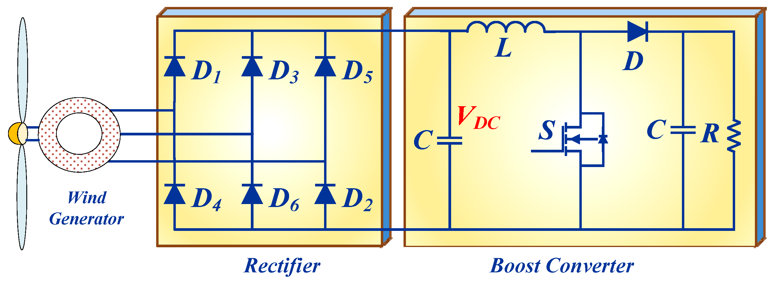
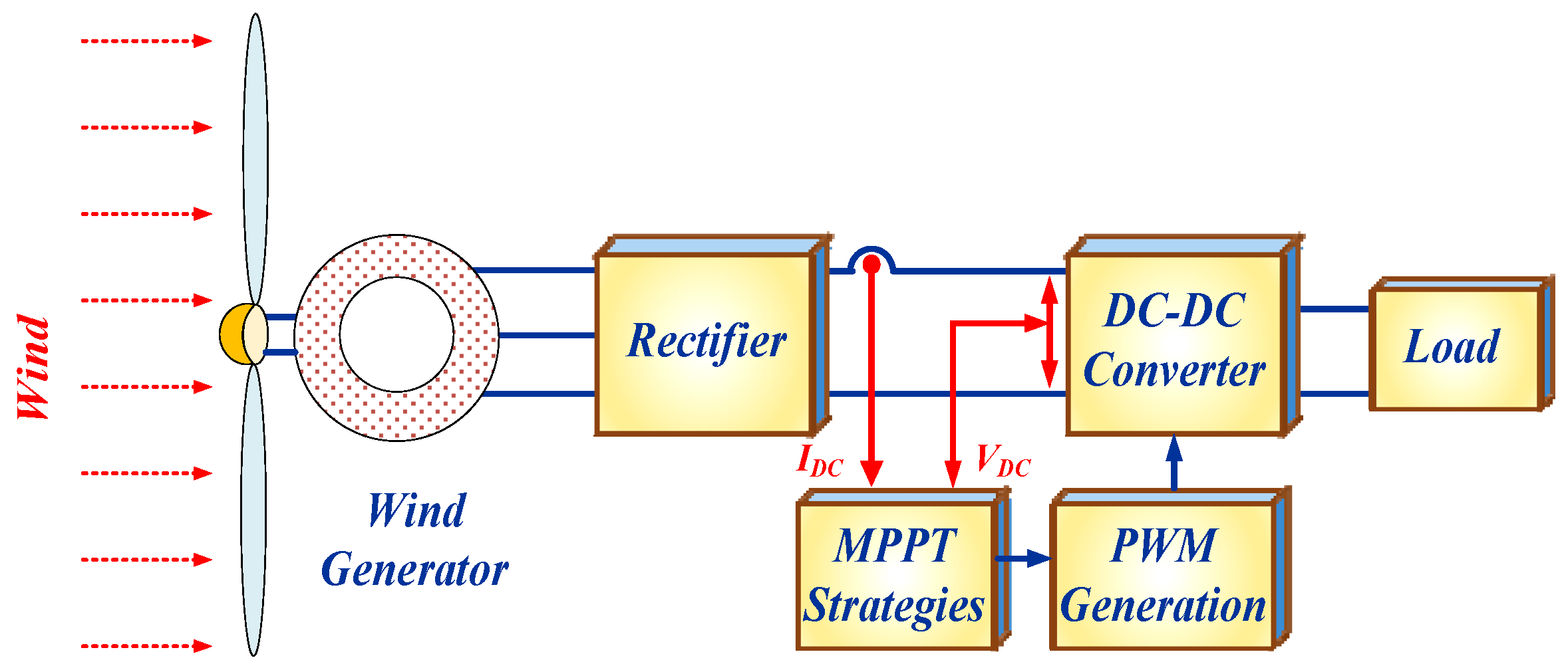
2. WECS Configuration

The schematic of WECS to which MPPT algorithm will be applied is shown in Figure 1. The wind turbine is directly coupled to the wind generator. The permanent magnet synchronous generator (PMSG) is used in this paper. The PMSG has an advantage of gearless operation, and it is coupled directly to the turbine, which reduces the size and complexity of the system. The load connected to the power converter can be replaced by a unity power factor inverter for a grid integration system. In this paper, resistor load is used for a standalone system application. The parameters of the wind turbine and generator are chosen as the AEOLOS-H 3 kW system.

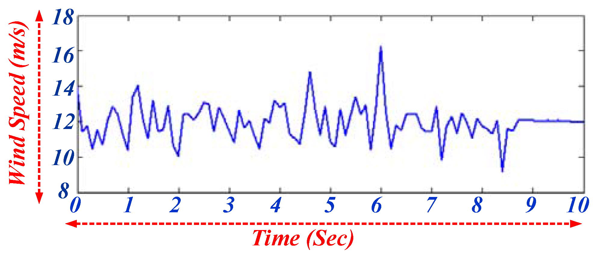
2.1. Wind Turbine Model

The mechanical power ( P m ) of wind is expressed defined as [22]:
P m = 1 2 π ρ R 2 V s 3 ,
where ρ is the air density, R is the radius of the turbine, and V s is the wind speed. The actual mechanical power ( P a ) captures by the wind blade can be expressed as:
P a = 1 2 π ρ R 2 V s 3 C p ( β , λ ) ,
where C p ( β , λ ) is power coefficient, which is a nonlinear function of pitch angle β and tip speed ratio (TSR) λ , which is described as [23],
C p ( λ , β ) = 0.5176 ( 116 1 λ i 0.4 β 5 ) 21 ( 1 λ i ) + 0.0068 λ ,
1 λ i = 1 λ + 0.08 β 0.035 β 3 + 1 ,
λ = R ω r / V ω ,
where ω r is the rotational speed of a WECS system.
The total mechanical torque T m generated by the wind turbine is expressed as [24]:
T m = 1 2 π ρ R 2 V s 3 C p ( β , λ ) ω r .

2.2. PMSG Model

The mechanical torque ( T m ) and electrical torque ( T e ) of a three-phase PMSG generator used in this study are expressed as [25]:
T m = P m ω r ,
T e = 2 P e ω r n p ,
where P m , P e are mechanical and electrical power obtained, respectively. ω r denotes mechanical rotational speed and n p represents number of poles used in PMSG. In general, the dynamic motion of PMSG generator is represented as
T e = J e q d ω r d t + D ω r + T m .
Here, D represents the rotational damping and J e q represents the equivalent inertia of wind turbine and generator.

3. MPPT Technique

The MPPT technique is implemented to extract the maximum power from available wind speed by tracking the peak point. In this paper, the DC-link voltage is used to track the maximum power point and generates the appropriate duty cycle for the switch in the DC–DC converter as shown in Figure 2. The MPPT algorithm implemented in this paper are described below.

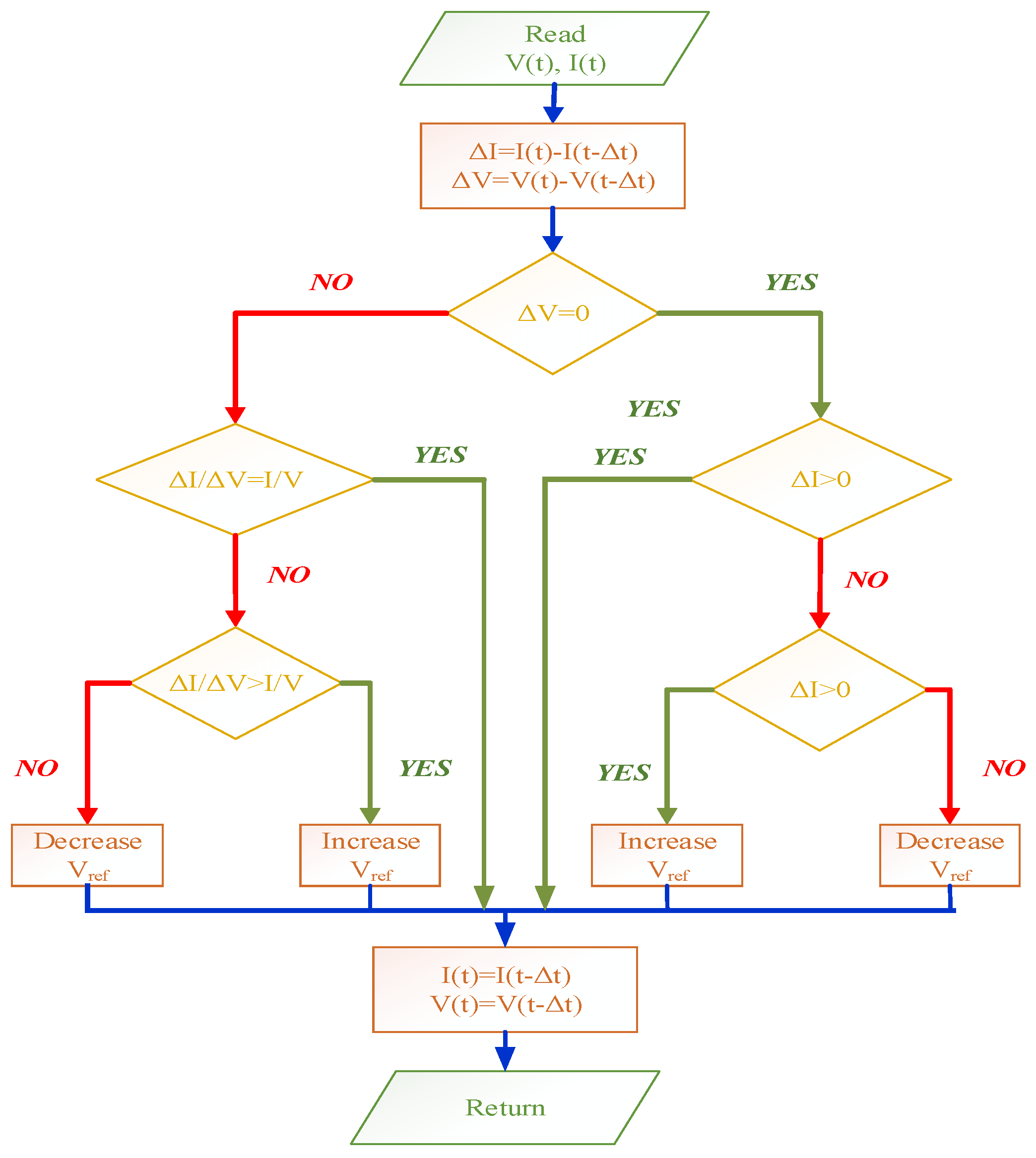
3.1. Perturb and Observe Algorithm

The P&O algorithm is the simplest and classical form of sensorless MPPT control technique present in the literature. The flowchart of P&O control system is shown in Figure 3. The direction of perturbation depends upon the change in observed power variable. The step size of the perturbation in P&O determines the efficiency and the convergence speed of the algorithm. Hence, fixed step size P&O algorithms are not implemented in the recent system since they deteriorate the overall performance of the system [26]. The convergence speed of P&O algorithm can be enhanced when large perturbation step size is used, but the efficiency of the MPPT is depreciated. The smaller step size is implemented to improve the system efficiency, but the convergence speed to track the maximum power point (MPP) is low. Thus, to overcome this, an adaptive step size P&O algorithm is developed where the step size is altered according to the demand and the perturbation variable. In adaptive step size, the large step size is implemented when the operating point is far away from the MPP and small step size when the operating point is close enough to MPP. With the implementation of adaptive step size, the P&O algorithm can achieve faster convergence speed and high efficiency. However, the wind velocity is highly nonlinear in nature. The rated voltage is considered as 380 V. Thus, the computation time for the P&O is not sufficient enough to compute the corresponding duty cycle, which misleads the perturbation direction [10].
Figure 3 represents a step-by-step procedure of the P&O based MPPT algorithm to track the maximum available from the wind system. The generated voltage and current are used as the control parameters. The obtained values are calculated using the previous step output to obtain the rate of change in voltage and current. If there is no change in obtained voltage, the rate of change of current is validated. If the voltage is in a positive direction, then the same duty cycle is used; otherwise, the duty cycle is increased or decreased based on the comparison of obtained current and previous step current. The perturbation frequency for the proposed system is considered as 0.1 Hz with a maximum step change of 10 V.

3.2. Back Propagation Algorithm

Feed forward neural network is most significant and a widely used artificial neural network. The ANN considered in this paper is trained by the back propagation (BP) using the Levenberg–Marquardt (LM) based optimization technique. LM is one of the most supervised learning algorithms for the feed-forward neural network [27]. The back propagation neural network (BPNN) provides a desired output based on the input based on the training and weight parameters.
In this paper, BPNN uses output DC voltage and current as the input variable and generates duty cycle to control the switch of DC/DC converter in order to obtain desired performance [28]. The BPN is trained with two hidden layers; thus, they have four layers: an input layer, hidden layer I, hidden layer II and an output layer. The nodal operation of BPN is processed in these layers. The modeling of each layer is described as follows [29].
The input signal given to the BPN is denoted as x and y as the targeted output. Then, the matrix of the input and output signal is represented as
x = [ x 1 x 2 x 3 x n ] ,
y = [ y 1 y 2 y 3 y n ] .
The samples of the matrix of input signal are taken as 820 by 2, and output signal as 820 by 1.
The input signals of the system are processed in this layer. This layer calculates the value z, which is fed into the next layer. This layer determines the minimum and maximum values of x and y:
z = ( x x m i n ) k + y m i n ,
where k is the gain that is given by
k = y m a x y m i n x m a x x m i n .
The output of input layer z is given as input in this layer. The weight w 1 and bias b 1 are calculated in the training period. The output of hidden layer I h 1 is given as
h 1 = ( z w 1 + b 1 ) l o g   s i g m o i d .
This control strategy is designed for three neurons; thus, the dimension of weight matrix is 820 by 3. In addition, the bias matrix is calculated as 2 by 3.
The output of hidden layer h 1 is given as the input for hidden layer II. The weight and bias of this layer are considered as w 2 and b 2 , respectively. The output of hidden layer II h 2 is given as
h 2 = ( h 1 w 2 + b 2 ) l o g   s i g m o i d .
The corresponding duty cycle ratio is obtained in the output layer. The input of this layer h 2 is subjected to reverse mapping to achieve the desired output. The output of this layer D is processed to feed as the input to the wind turbine:
D = ( h 2 y m i n ) k + x m i n .
Thus, using the above control strategy, a corresponding duty cycle ratio for DC/DC converter is obtained based on the wind speed.

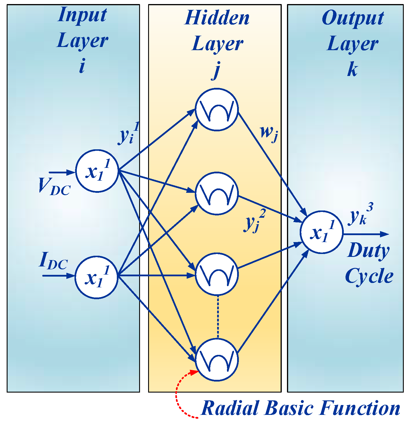
3.3. Radial Basis Function Network Algorithm

RBFN is a type of feed-forward neural network, which uses radial basis network as an activation function [13]. The radial basis network is configured using the distance between the input and the prototype vector. The training process of the RBFN network is performed in two stages. In the initial stage, the unsupervised method is implemented where the parameter is governed by the radial basis function. In the second stage, the supervised training method is employed to train the weights [14]. The supervised training method is the same as the back propagation algorithm [16].
In this paper, RBFN is employed to generate the duty cycle for the converter. Generated voltage and current is fed to the input neurons of the RBFN, which is used to compute the duty cycle as the output neuron. The basic nodes of operation are characterized by three layers, namely, input layer, a hidden layer and outer layer as shown in Figure 4 [13].
The inputs of two neurons in this layer are transmitted directly to the consecutive layer. The net input and output in this layer are expressed as
n e t i 1 = x i 1 ( N ) y i 1 ( N ) = f i 1 ( n e t i 1 ( N ) ) = n e t i 1 ( N ) } i = 1 , 2 ,
where x i 1 is the input layer which consists of x 1 1 as the wind speed and x 2 1 as the generator speed. The n e t i 1 represents the net sum of nodes of input layer and y i 1 is the output of input layer, which is fetched to a hidden layer with respect to node i .
The neurons in the hidden layer perform a Gaussian function that is used as the membership function in RBFN. The net input and output of hidden layer are expressed as
n e t j 2 ( N ) = ( X M j ) T j ( X M j ) y j 2 ( N ) = f j 2 ( n e t j 2 ( N ) ) = e x p ( n e t j 2 ( N ) ) } j = 1 , 2 , , 800 ,
where M j = [ m 1 j , m 2 j , , m i j ] T is the Gaussian function mean and the standard deviation of the Gaussian function is denoted as j = d i a g [ 1 / σ 1 j 2 , 1 / σ 2 j 2 , , 1 / σ i j 2 ] T .
The output layer computes a single neuron, which is determined by node k. The duty cycle is generated in this layer by summing the all the incoming signals with linear activation function:
n e t k 3 = j w j y j 2 ( N ) y k 3 ( N ) = f k i 3 ( n e t k 3 ( N ) ) = n e t k 3 ( N ) = β r e f } ,
where w j is the weight, which interlinks a hidden layer with the output layer.
The supervised learning is implemented once the RBFN is initialized to train the system. The training method is similar to that of back propagation algorithm, which adjusts the RBFN parameters using the training patterns. The error of each layer is computed and updated by the supervised learning algorithm in order to track the performance of wind system and act appropriately.

4. Converter Modelling

The converter is employed in WECS in order to enhance the generated voltage to the desired high voltage as per the load requirement. The DC/DC converter implemented in this paper is a converter from 230 V generator voltages to 380 V, which is the standard bus voltage for a DC microgrid. In this paper, boost converter, single ended primary inductor converter (SEPIC) and fused SEPIC-voltage doubler are implemented, which are described in this section.

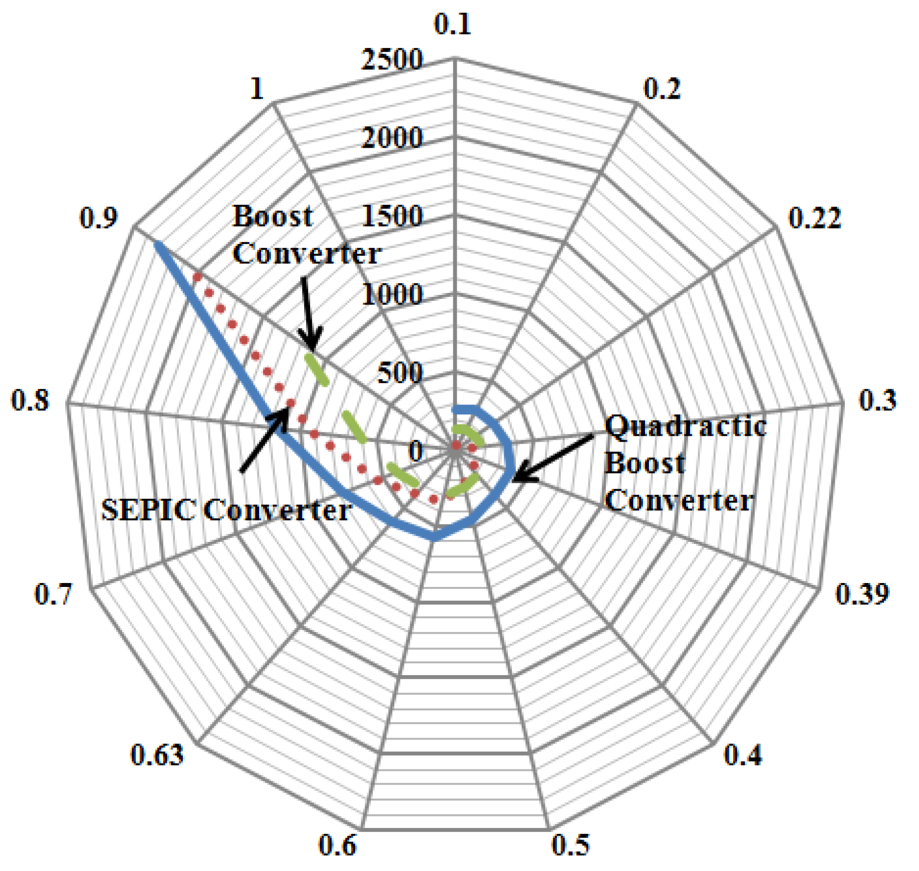
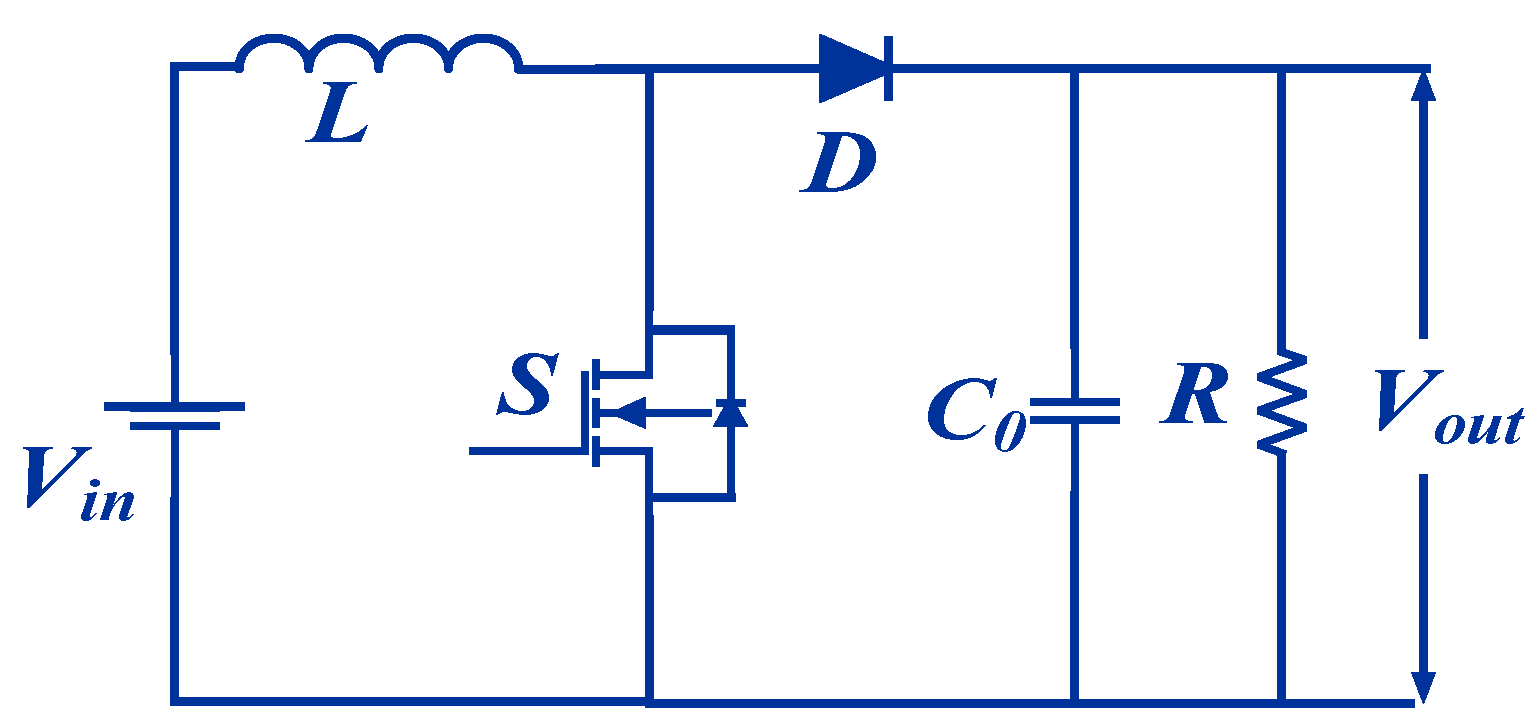
4.1. Boost Converter

The boost converter is used to obtain high continuous output voltage than the input voltage. The voltage of the desired value can be obtained using a boost converter [16]. Boost is the basic conventional DC/DC converter, which is operated using a single switch. The boost converter [30]. consists of an inductor, capacitor, a switch and a diode for its operation as shown in Figure 5 .When the switch is turned ON, the diode gets reversed biased; thus, the current starts increasing charging the inductor; and a capacitor supports the load. When the switch is turned OFF, the diode becomes forward biased and the inductor current starts decreasing; the capacitor charge starts increasing: both inductor and DC source supports the capacitor and the load. The modelling of boost converter is as follows [30]:
V o = V i 1 D ,
where V o and V i are the output voltage and input voltage, respectively. D refers to the duty cycle.
The inductor and capacitor of the boost converter is calculated by
L = V i min Δ I L × f s × D ,
C s = I o × D Δ V c s × f s .
The ON–OFF period of the switch in boost converter is slow. Wind speed, which is highly nonlinear, fails to provide sufficient input to the boost controller to track the maximum power point. The switching losses of boost converter are high due to frequent ON–OFF of the switch [30]. The rapid variation in wind speed also increases the stress across the switch.

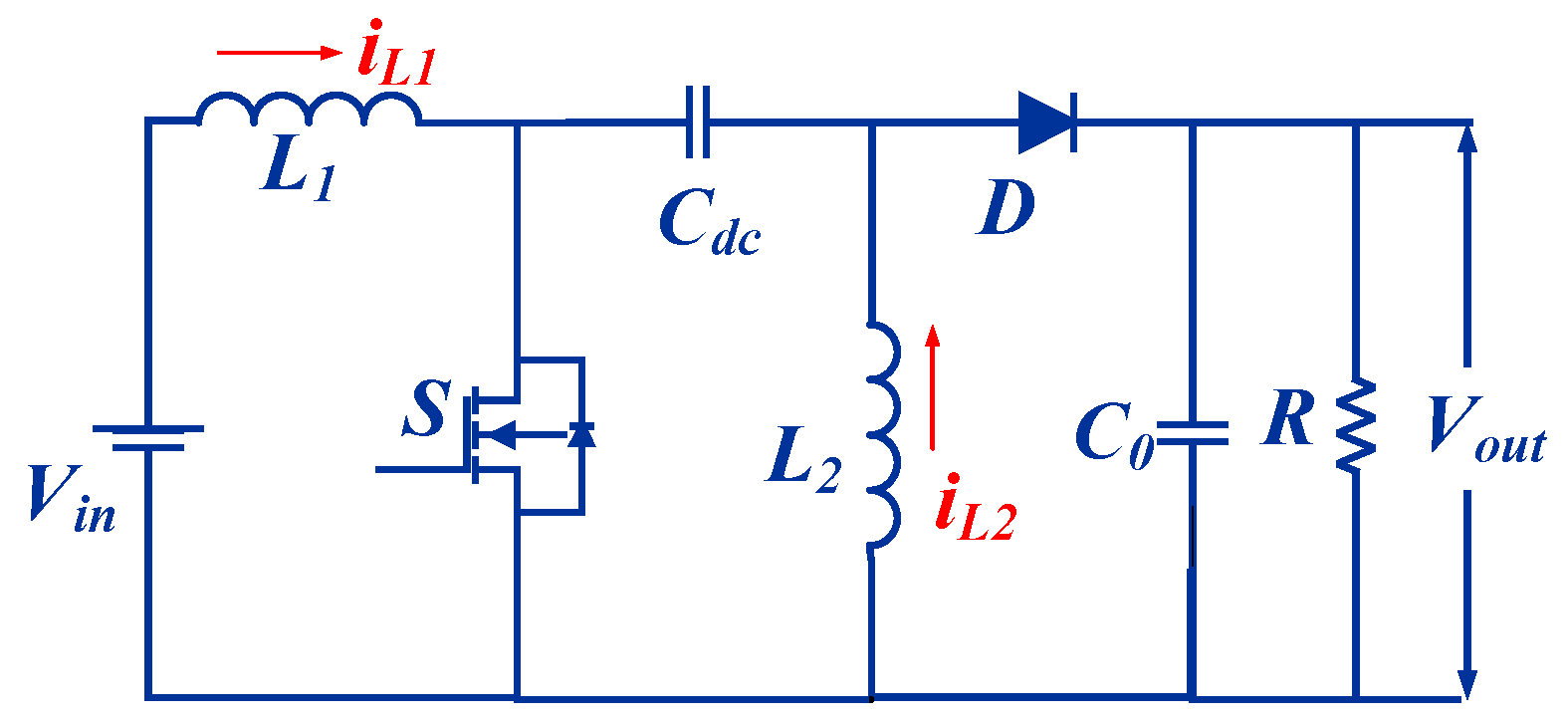
4.2. SEPIC Converter

SEPIC converter is a category of the buck-boost converter, which follows both the boost and buck operation. Since wind speed is intermittent in nature, it may exceed an above-rated wind speed; thus, a SEPIC converter is operated in buck mode during that condition, whereas, in a boost converter, WECS is subjected to a stall condition. SEPIC can maintain the output voltage to optimal value irrespective of the input voltage without any polarity reversal.
A SEPIC converter consists of a switch, dual inductors, dual capacitors and a diode as shown in Figure 6. SEPIC converter operates in balancing mode; the diode gets reversed biased when the switch is in an ON condition [31]. Inductor L1 starts storing the charge, whereas the capacitor Cdc supports the load where the charge is transferred through inductor L2 and capacitor Co. When the switch is in OFF state, the diode becomes forward biased. The energy that is stored in inductor L1 charges the capacitor Cdc. The current ripple during the buck mode operation of a SEPIC converter (during wind speed above rated value) is lower when compared with another conventional converter. The soft-computing commutation of a SEPIC converter can be enhanced when the system is included with a protective device like snubber circuit. The capacitor Cdc increases the gain of the SEPIC converter as they get charged during boost operation, which is reflected in the output during commutation period. The duty cycle and parasitic element of a SEPIC converter are designed as follows [32]:
D = V o V i + V o ,
L 1 = L 2 = L = V i min Δ I L × f s × D ,
C d c = I o × D Δ V c s × f s ,
C o = I o × D V r i p p l e × 0.5 × f s ,
where Vo and Vi are the output and input voltages, respectively. fs is the switching frequency. Io and IL are the output current and inductor ripple current. Vripple refers to ripple between the voltage and D is the duty cycle.

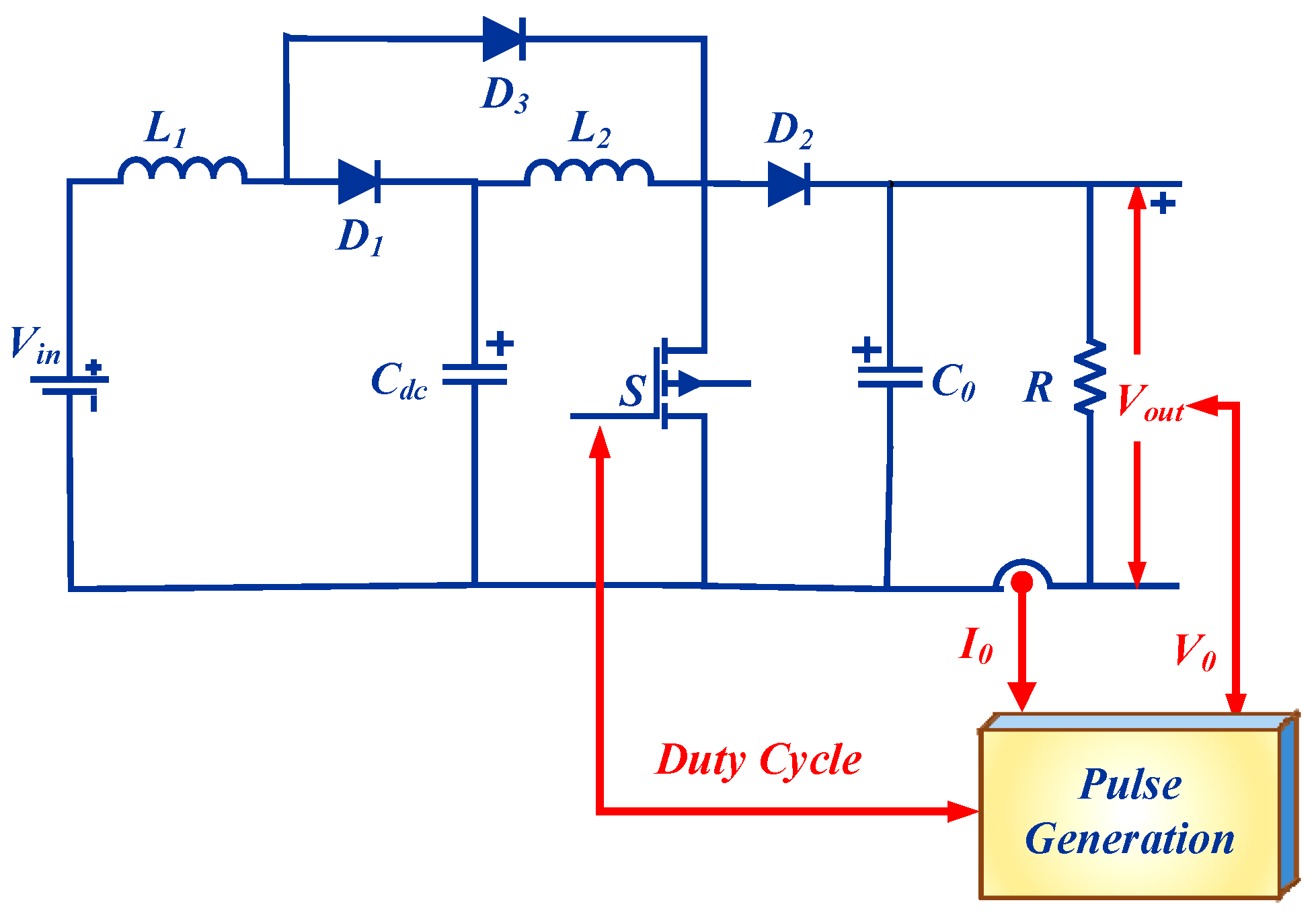
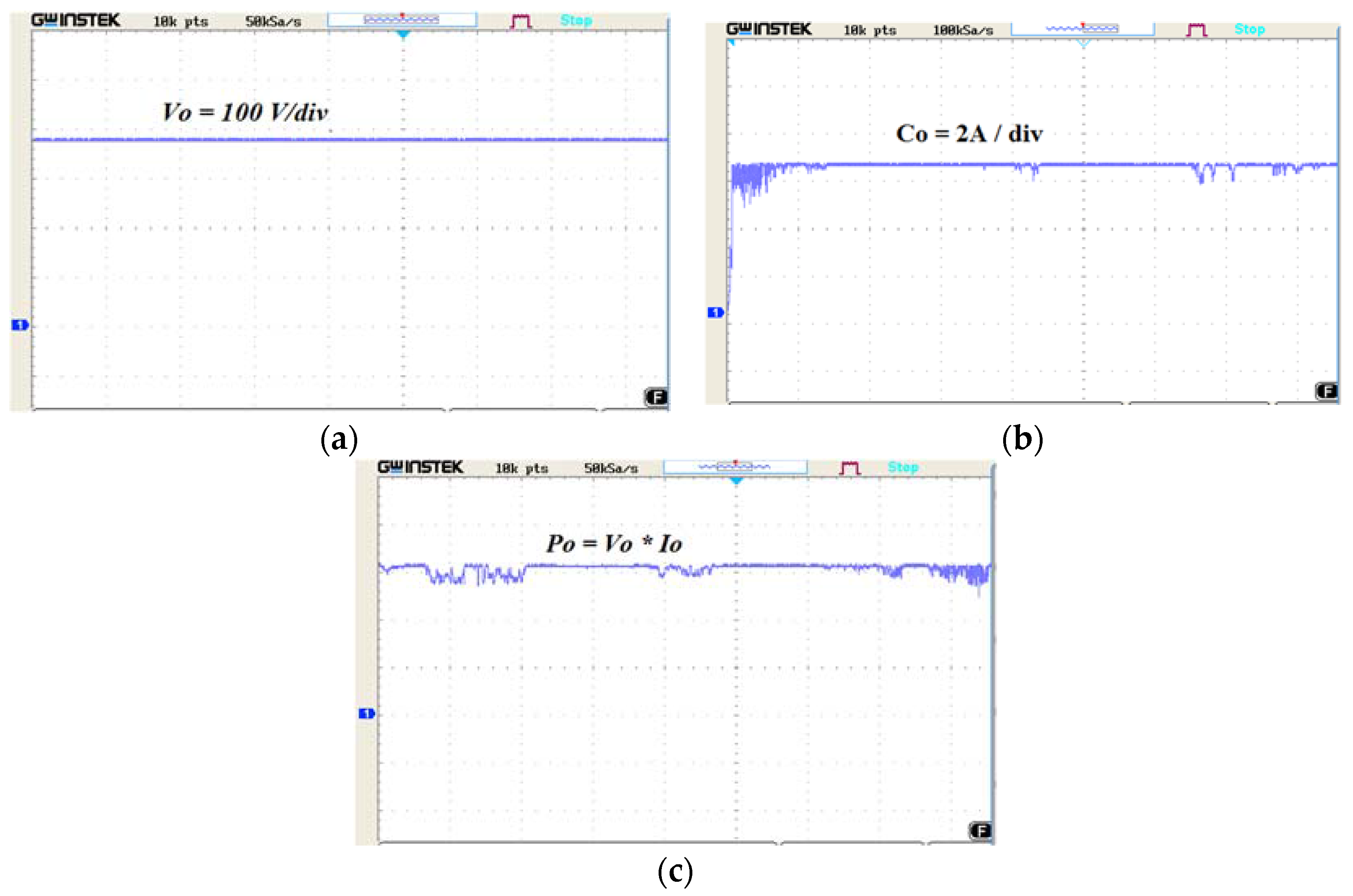
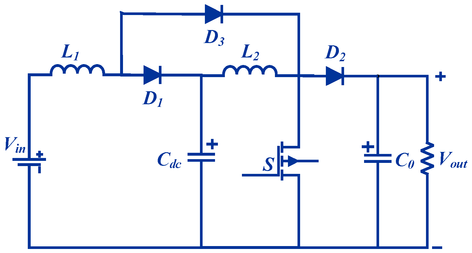
4.3. Quadratic Boost Converter

Quadratic refers to combining of two series converters and eliminating the need for a second switch. The quadratic boost converter (QBC) is similar to a cascaded boost converter, which is used to obtain a high voltage conversion ratio. The cascaded boost converter requires a dual control strategy to control dual switch, whereas QBC requires only a single control strategy, since they have only one switch. QBC eliminates the requirement of the additional driver circuit and thus further enhances the output voltage by minimizing the losses [33]. Thus, QBC is used for many renewable energy applications. QBC requires two inductors, three diodes, two capacitors and a single switch as shown in Figure 7. QBC operates similarly to boost converters. When the switch is turned ON, both the diodes (d1 and d2) are in a reversed biased condition and the input current flows through the parallel diode (d3) and inductor (L1). The load is supplied using the capacitor (Co). The inductor (L2) is supplied using the capacitor (Cdc). When the switch is turned to the OFF condition, the diodes (d1 and d2) are in the forward biased state. The diode (d3) is reversed biased. The inductors (L1 and L2) supply the energy to the load. Simultaneously, the capacitors (C1 and C2) are charged using the inductors. The modellings of parameters of QBC are as follows [34,35,36]:
V o = V i ( 1 D ) 2 .
The inductors are selected as follows:
L 1 = V i min 2 × Δ I L 1 × f s × D ,
Δ I L 1 = I o ( 1 D ) 2 ,
L 2 = V i min 2 × Δ I L 2 × f s × D ,
Δ I L ( n ) = I o ( 1 D ) .
The capacitors in QBC are selected as
C d c = I o × D ( 1 D ) Δ V c 1 × f s ,
V c 1 = V i ( 1 D ) ,
C o = I o × D Δ V c 2 × f s ,
V c 2 = V c 1 ( 1 D ) .
The notations of the parameters are the same as denoted for the boost converter.

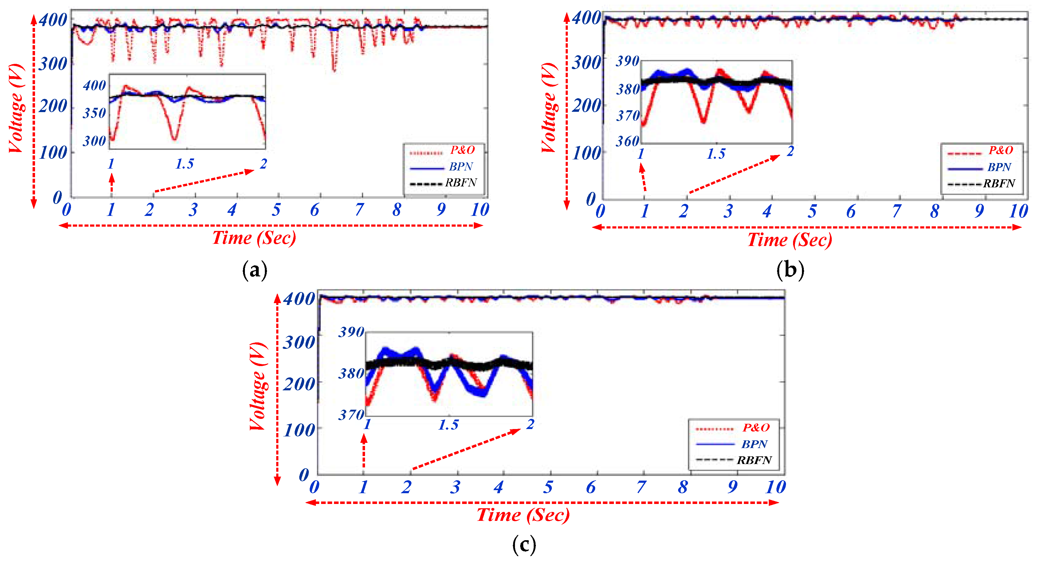
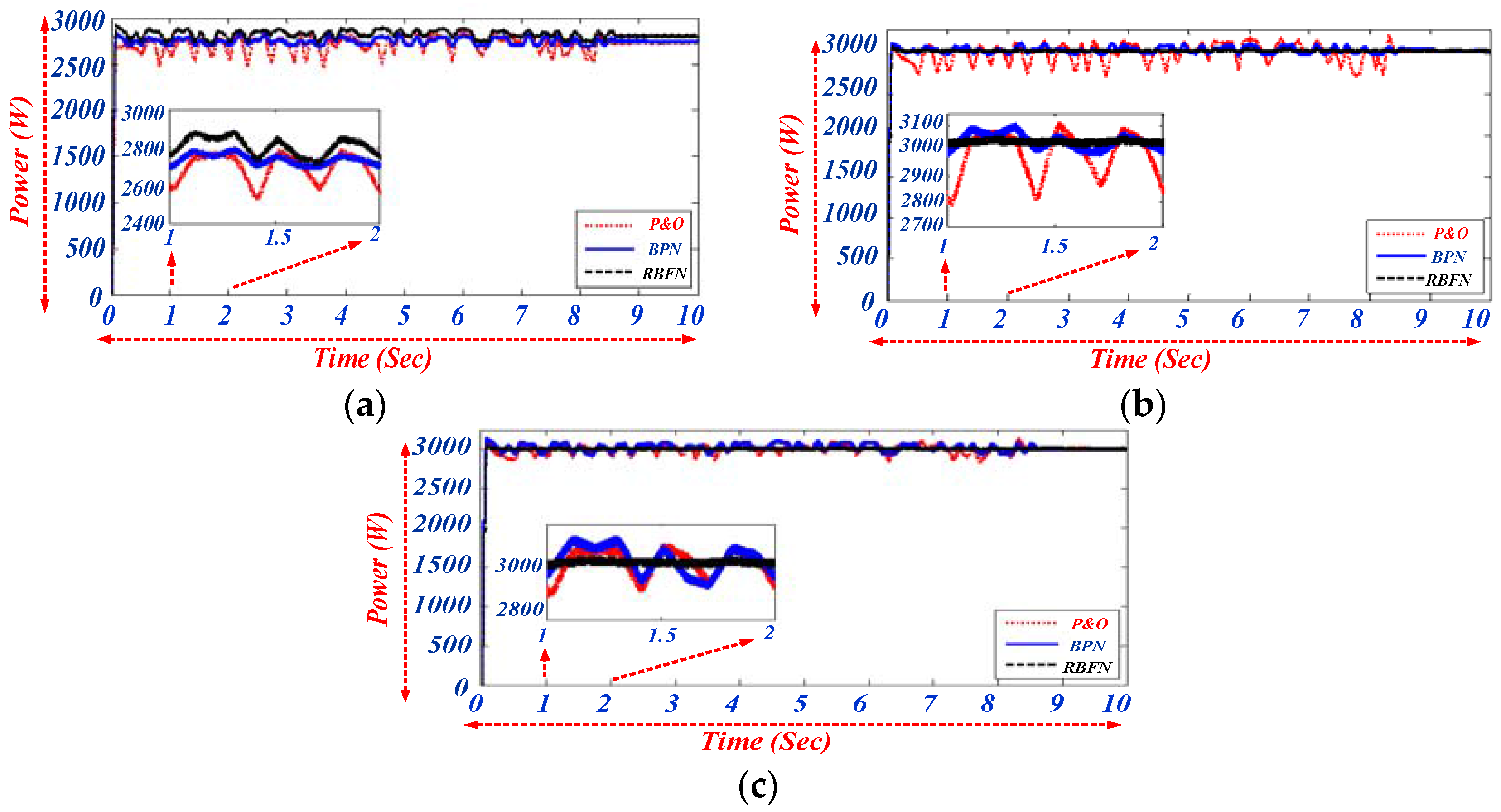
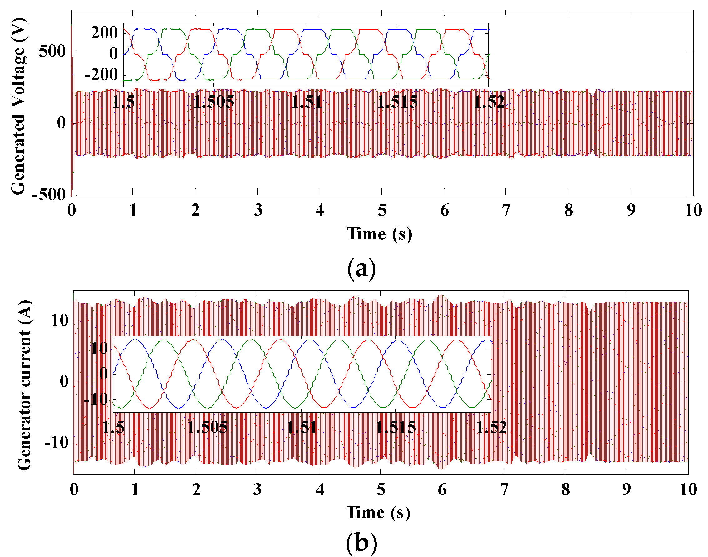
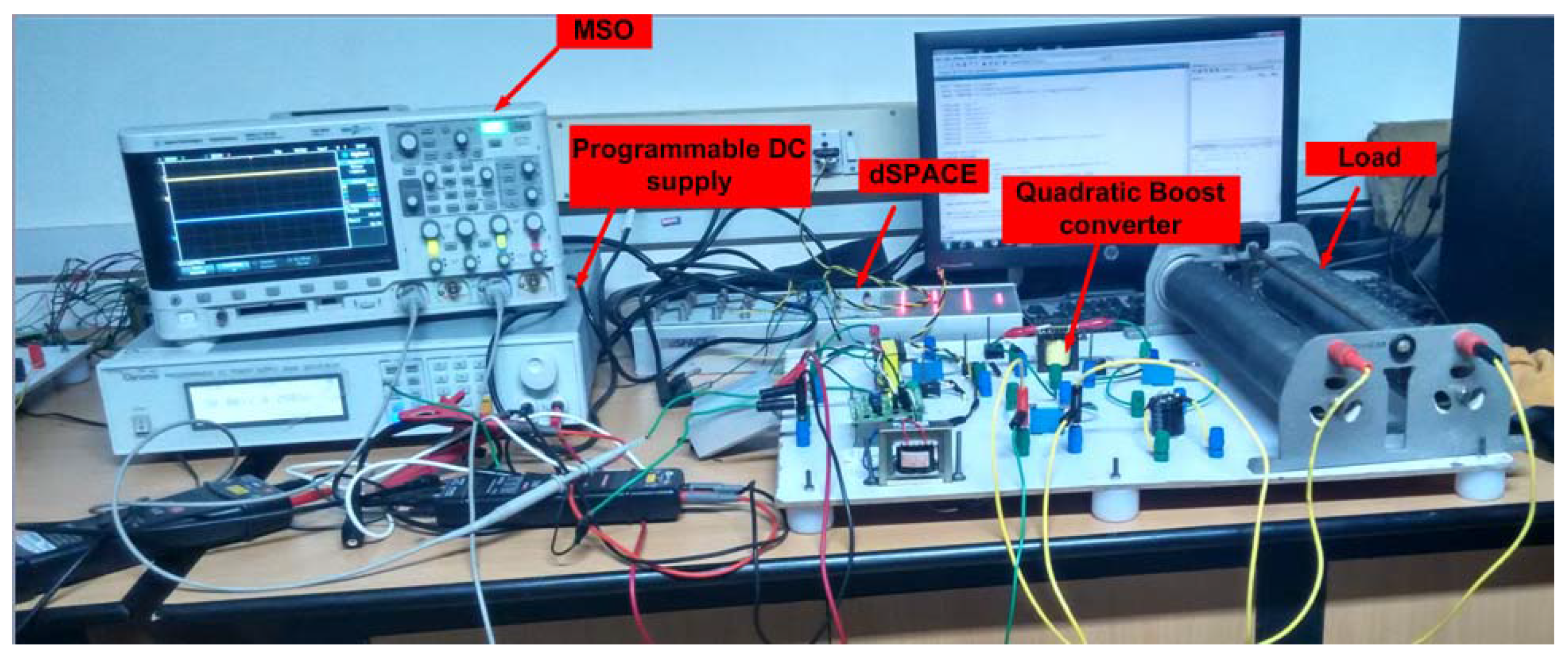
5. Results and Discussion

In this section, the WECS is implemented along with P&O, BPN and RBFN control strategies for different power converters such as Boost, SEPIC, and Quadratic-Boost and simulated in MATLAB/Simulink software (R2017a, Mathworks, Bangalore, Karnataka, India, 2017). The performance of each MPPT technique with different DC/DC converters is validated for rapid and inconsistent wind speed. To get the real time wind turbine analysis, the parameters of Aeolos 3 kW system design (Lotus Energy Technology, Qingdao, China) are utilized in this paper as mentioned in Table 1. The overall simulation diagram for RBFN based quadratic boost converter is shown in Figure 8.
The parameters of Boost converter, SEPIC converter and Quadratic Boost converter used in this study are shown in Table 2. The MPPT control strategy adapted in this paper are approximated to overcome the nonlinearity of the system and also to extract the maximum available power at the particular wind speed. Wind speed pattern that is used in this research paper is highly intermittent in nature and a key parameter for the MPPT control strategy is shown in Figure 9. The average wind speed of 12 m/s is considered for this paper, which is also the rated wind speed. The MPPT control algorithm is utilized for the both the operating region (below-rated wind speed and above-rated wind speed). The MPPT extracts the maximum available power from the available wind velocity when the wind speed is below the rated value. In addition, during the higher wind speed region, the MPPT control strategy tends to optimize the voltage and power of the WECS to the rated value.
Simulation studies for the rapid wind variations are performed for Boost, SEPIC, and Quadratic-Boost converter for different MPPT control strategies like P&O, BPN, and RBFN to test their accuracy. The results of the different DC/DC converter with different MPPT control strategies are shown in Figure 10 and Figure 11.
Figure 10 shows the comparison of DC voltage output for the above-mentioned DC/DC converter, which is implemented with P&O, BPN, and RBFN control techniques. Figure 10a shows the output voltage when Boost converter is implemented and Figure 10b shows the DC output voltage when the SEPIC topology is implemented in WECS. The RBFN based MPPT control strategy provides higher results than the P&O and BPN based control technique. The output voltage when the quadratic-boost converter is implemented is shown in Figure 10c. Thus, from the above results, it can be observed that the Quadratic-boost converter delivers higher voltage gain, whereas Boost converter and SEPIC converter have lesser gain value. The WECS performs in a stable condition and delivers constant rated voltage of 380 V in all operating regions only when the RBFN based control strategy is implemented along with the Quadratic boost converter.
The ability of MPPT controllers to extract the maximum available power from the wind speed is shown in Figure 11. The power output of Boost and SEPIC converter is shown in Figure 11a,b. From the results, it can be observed that the RBFN based MPPT control strategy produces higher power output than that of P&O and BPN control strategy. The output power obtained when a Quadratic boost converter is used is shown in Figure 11c. From the results, it can be concluded that the combination of Quadratic boost converter along with the RBFN based MPPT technique provides better results and can optimize the output power when the wind speed surpasses the rated value. The P&O controller on average extracts lower power than that of RBFN controllers. The speed of convergence of the P&O controller is slow and, since the wind is highly intermittent, it cannot determine the exact duty cycle of current wind speed. The BPN controller strategy provides enhanced results but fails at the above-rated wind speed region, and the convergence speed is also lower than the RBFN control technique. The generated voltage and current of PMSG converter for the rapid variation of wind speed is shown in Figure 12a,b, respectively. The hardware implementation of the Quadratic boost converter with RBFN based MPPT control technique is shown in Figure 13 and Figure 14. The region is considered between time ranges of 1.2 s to 1.5 s to show the clear output for the hardware results.
The overall performance comparison of maximum power extracted using Boost converter, SEPIC converter, and Quadratic Boost converter is shown in Table 3. The average output DC voltage obtained in both the operating regions when the MPPT control strategy is applied is shown in Table 4. The DC output voltage obtained corresponding to the duty cycle is shown in Figure 15. The optimum voltage of 380 V is kept as the rated voltage for SEPIC converter and a Quadratic boost converter. The 380 V DC voltage is termed as the standard value for DC microgrid. The switching loss and diode loss associated with the boost converter, SEPIC and Quadratic boost converters are shown in Table 5.

6. Conclusions

In this paper, a novel configuration of integrating Quadratic boost converter with RBFN based MPPT control strategy is implemented for wind energy conversion system. Various MPPT strategies, namely P&O and BPN and DC/DC converters such as Boost and SEPIC are also discussed in detail. The main aim of the MPPT control technique is to maximize the output power of wind energy at low wind speed and optimize the power to optimum value during high wind speed by varying the duty cycle according to the wind speed. A quadratic boost converter that can provide high voltage gain is employed so that the WECS can be operated at a higher voltage and also achieve high performance. The proposed topology is then compared with the Boost and SEPIC based configuration in order to validate their performance. MATLAB/Simulink software is employed to test the design and validate the results. From the analysis, it is concluded that an RBFN based MPPT controller with a Quadratic boost converter provides more effective results than that of P&O and BPN based methods in terms of maximum power extraction. The major advantage of RBFN controllers is the smaller settling time when compared to P&O and BPN controllers; thus, there are fewer oscillations during the sudden gust in wind speed. Hence, the proposed configuration can be implemented in real time for better and improvised operation of the wind energy conversion system.

Acknowledgments

No source of funding for this research investigation.

Author Contributions

Ramji Tiwari and Kumar Krishnamurthy designed the experiments; Ramji Tiwari and Ramesh Babu Neelakandan performed the experiments; Ramesh Babu Neelakandan and Sanjeevikumar Padmanaban wrote the paper; Patrick William Wheeler analyzed the data.

Conflicts of Interest

The authors declare no conflict of interest.

References

  1. Tiwari, R.; Babu, N.R. Recent developments of control strategies for wind energy conversion system. Renew. Sustain. Energy Rev. 2016, 66, 268–285. [Google Scholar] [CrossRef]
  2. Tiwari, R.; Babu, N.R.; Sanjeevikumar, P.; Martirano, L.; Siano, P. Coordinated DTC and VOC control for PMSG based grid connected wind energy conversion system. In Proceedings of the 2017 IEEE International Conference on Environment and Electrical Engineering and 2017 IEEE Industrial and Commercial Power Systems Europe (EEEIC/I&CPS Europe), Milan, Italy, 6–9 June 2017; pp. 1–6. [Google Scholar]
  3. Daly, P.A.; Morrison, J. Understanding the potential benefits of distributed generation on power delivery systems. In Proceedings of the Conference on Rural Electric Power, Little Rock, AR, USA, 29 April–1 May 2001; pp. 1–13. [Google Scholar]
  4. Dalala, Z.M.; Zahid, Z.U.; Yu, W.; Cho, Y.; Lai, J. Design and analysis of an MPPT technique for small-scale wind energy conversion systems. IEEE Trans. Energy Convers. 2013, 28, 756–767. [Google Scholar] [CrossRef]
  5. Barakati, S.M.; Kazerani, M.; Aplevich, J.D. Maximum power tracking control for a wind turbine system including a matrix converter. IEEE Trans. Energy Convers. 2009, 24, 705–713. [Google Scholar] [CrossRef]
  6. Li, D.Y.; Song, Y.D.; Gan, Z.X.; Cai, W.C. Fault-Tolerant Optimal Tip-Speed-Ratio Tracking Control of Wind Turbines Subject to Actuation Failures. IEEE Trans. Ind. Electron. 2015, 62, 7513–7523. [Google Scholar] [CrossRef]
  7. Nasiri, M.; Milimonfared, J.; Fathi, S.H. Modeling, analysis and comparison of TSR and OTC methods for MPPT and power smoothing in permanent magnet synchronous generator-based wind turbines. Energy Convers. Manag. 2014, 86, 892–900. [Google Scholar] [CrossRef]
  8. Daili, Y.; Gaubert, J.P.; Rahmani, L. Implementation of a new maximum power point tracking control strategy for small wind energy conversion systems without mechanical sensors. Energy Convers. Manag. 2015, 97, 298–306. [Google Scholar] [CrossRef]
  9. Saravanan, S.; Babu, N.R. Modified High Step-Up Coupled Inductor based DC-DC Converter for PV Applications. Gazi Univ. J. Sci. 2016, 29, 981–986. [Google Scholar]
  10. Linus, R.M.; Damodharan, P. Maximum power point tracking method using a modified perturb and observe algorithm for grid connected wind energy conversion systems. IET Renew. Power. Gener. 2015, 9, 682–689. [Google Scholar] [CrossRef]
  11. Tiwari, R.; Babu, N.R. Fuzzy logic based MPPT for permanent magnet synchronous generator in wind energy conversion system. IFAC-PapersOnLine 2016, 49, 462–467. [Google Scholar] [CrossRef]
  12. Kumar, D.; Chatterjee, K. Design and analysis of artificial bee-colony-based MPPT algorithm for DFIG-based wind energy conversion systems. Int. J. Green Energy 2017, 14, 416–429. [Google Scholar] [CrossRef]
  13. Assareh, E.; Biglari, M. A novel approach to capture the maximum power from variable speed wind turbines using PI controller, RBF neural network and GSA evolutionary algorithm. Renew. Sustain. Energy Rev. 2015, 51, 1023–1037. [Google Scholar] [CrossRef]
  14. Babu, N.R.; Arulmozhivarman, P. Forecasting of wind speed using artificial neural networks. Int. Rev. Model. Simul. 2012, 5, 2276–2280. [Google Scholar]
  15. Poultangari, I.; Shahnazi, R.; Sheikhan, M. RBF neural network based PI pitch controller for a class of 5-MW wind turbines using particle swarm optimization algorithm. ISA Trans. 2012, 51, 641–648. [Google Scholar] [CrossRef] [PubMed]
  16. Saravanan, S.; Babu, N.R. RBFN based MPPT algorithm for PV system with high step up converter. Energy Convers. Manag. 2016, 122, 239–251. [Google Scholar] [CrossRef]
  17. Yaramasu, V.; Wu, B. Predictive control of a three-level boost converter and an NPC inverter for high-power PMSG-based medium voltage wind energy conversion systems. IEEE Trans. Power Electron. 2014, 29, 5308–5322. [Google Scholar] [CrossRef]
  18. Koutroulis, E.; Kalaitzakis, K. Design of a maximum power tracking system for wind-energy-conversion applications. IEEE Trans. Ind. Electron. 2006, 53, 486–494. [Google Scholar] [CrossRef]
  19. Gules, R.; Dos Santos, W.M.; Dos Reis, F.A.; Romaneli, E.F.; Badin, A.A. A modified SEPIC converter with high static gain for renewable applications. IEEE Trans. Power Electron. 2014, 29, 5860–5871. [Google Scholar] [CrossRef]
  20. Chen, Z. PI and sliding mode control of a Cuk converter. IEEE Trans. Power Electron. 2012, 27, 3695–3703. [Google Scholar] [CrossRef]
  21. Balamurugan, T.; Manoharan, S. Fuzzy controller design using soft switching boost converter for MPPT in hybrid system. Int. J. Soft Comput. Eng. 2012, 2, 87–94. [Google Scholar]
  22. Tiwari, R.; Babu, N.R. Comparative Analysis of Pitch Angle Controller Strategies for PMSG Based Wind Energy Conversion System. Int. J. Intell. Syst. Appl. 2017, 9, 62–73. [Google Scholar]
  23. Babu, N.R.; Arulmozhivarman, P. Wind energy conversion systems-a technical review. J. Eng. Sci. Technol. 2013, 8, 493–507. [Google Scholar]
  24. Alizadeh, M.; Kojori, S.S. Augmenting effectiveness of control loops of a PMSG (permanent magnet synchronous generator) based wind energy conversion system by a virtually adaptive PI (proportional integral) controller. Energy 2015, 91, 610–629. [Google Scholar] [CrossRef]
  25. Beddar, A.; Bouzekri, H.; Babes, B.; Afghoul, H. Experimental enhancement of fuzzy fractional order PI+ I controller of grid connected variable speed wind energy conversion system. Energy Convers. Manag. 2016, 123, 569–580. [Google Scholar] [CrossRef]
  26. Eldahab, Y.E.; Saad, N.H.; Zekry, A. Enhancing the tracking techniques for the global maximum power point under partial shading conditions. Renew. Sustain. Energy Rev. 2017, 73, 1173–1183. [Google Scholar] [CrossRef]
  27. Yilmaz, A.S.; Özer, Z. Pitch angle control in wind turbines above the rated wind speed by multi-layer perceptron and radial basis function neural networks. Expert Syst. Appl. 2009, 36, 9767–9775. [Google Scholar] [CrossRef]
  28. Chen, C.H.; Hong, C.M.; Ou, T.C. Hybrid fuzzy control of wind turbine generator by pitch control using RNN. Int. J. Ambient Energy 2012, 33, 56–64. [Google Scholar] [CrossRef]
  29. Babu, N.R.; Arulmozhivarman, P. Improving forecast accuracy of wind speed using wavelet transform and neural network. J. Electr. Eng. Technol. 2013, 8, 559–564. [Google Scholar] [CrossRef]
  30. Rahimi, M. Modeling, control and stability analysis of grid connected PMSG based wind turbine assisted with diode rectifier and boost converter. Int. J. Electr. Power Energy Syst. 2017, 93, 84–96. [Google Scholar] [CrossRef]
  31. Kumar, K.; Babu, N.R.; Prabhu, K.R. Design and Analysis of an Integrated Cuk-SEPIC Converter with MPPT for Standalone Wind/PV Hybrid System. Int. J. Renew. Energy Res. 2017, 7, 96–106. [Google Scholar]
  32. Lee, S.W.; Do, H.L. Zero-Ripple Input-Current High-Step-Up Boost–SEPIC DC–DC Converter With Reduced Switch-Voltage Stress. IEEE Trans. Power Electron. 2017, 32, 6170–6177. [Google Scholar] [CrossRef]
  33. Malik, M.Z.; Xu, Q.; Farooq, A.; Chen, G. A new modified quadratic boost converter with high voltage gain. IEICE Electron. Express 2017, 14, 20161176. [Google Scholar] [CrossRef]
  34. Ozdemir, S.; Altin, N.; Sefa, I. Fuzzy logic based MPPT controller for high conversion ratio quadratic boost converter. Int. J. Hydrog. Energy 2017, 42, 17748–17759. [Google Scholar] [CrossRef]
  35. Ramji, T.; Sanjeevikumar, P.; Ramesh Babu, N. Co-ordinated Control Strategies for Permanent Magnet Synchronous Generator Based Wind Energy Conversion System. Energies 2017, 10, 1493. [Google Scholar] [CrossRef]
  36. Kalaivani, C.; Sanjeevikumar, P.; Rajambal, K.; Bhaskar, M.S.; Mihet-Popa, L. Grid Synchronization of Seven-phase Wind Electric Generator using d-q PLL. Energies 2017, 10, 929. [Google Scholar] [CrossRef]
Figure 1. Basic configuration of wind energy conversion system (WECS).
Electronics 07 00020 g001
Figure 2. Proposed topology of maximum power point tracking (MPPT) and DC/DC converter. PWM: Pulse Width Modulation
Electronics 07 00020 g002
Figure 3. Flowchart of Perturb and Observe (P&O) based MPPT control strategy.
Electronics 07 00020 g003
Figure 4. Radial basis function network (RBFN) based MPPT technique.
Electronics 07 00020 g004
Figure 5. Configuration of Boost converter.
Electronics 07 00020 g005
Figure 6. Configuration of a single ended primary inductance converter (SEPIC) converter.
Electronics 07 00020 g006
Figure 7. Configuration of Quadratic Boost Converter.
Electronics 07 00020 g007
Figure 8. Simulation configuration of proposed topology.
Electronics 07 00020 g008
Figure 9. Wind speed input pattern.
Electronics 07 00020 g009
Figure 10. Voltage output of the WECS for (a) boost converter; (b) SEPIC converter; and (c) quadratic Boost converter with P&O, Back propagation network (BPN) and RBFN MPPT techniques.
Electronics 07 00020 g010
Figure 11. Power output of the WECS for, (a) Boost converter; (b) SEPIC converter; and (c) Quadratic Boost converter with P&O, BPN and RBFN MPPT techniques.
Electronics 07 00020 g011
Figure 12. Generated output parameters of permanent magnet synchronous generator (PMSG), (a) voltage; (b) current.
Electronics 07 00020 g012
Figure 13. Hardware setup of the Proposed converter with RBFN based MPPT control strategy.
Electronics 07 00020 g013
Figure 14. Experimental results output for RBFN based Quadratic boost converter, (a) output voltage; (b) output current; and (c) output power.
Electronics 07 00020 g014
Figure 15. Voltage waveform of Boost, SEPIC and Quadractic boost converters (radar plot).
Electronics 07 00020 g015
Table 1. Parameters of Aeolos 3 kW system. PMSG: permanent magnet synchronous generator.
ParametersRatings
Rated Power3 kW
Rated wind speed12 m/s
Cut-in wind speed3.0 m/s
Cut-out wind speed25 m/s
Frequency50 Hz
Voltage220–240 V
Rotor diameter5.0 m
Generator typeThree phase PMSG
Stator phase Resistance0.425 Ω
Armature Inductance0.000835 H
Number of Poles 4
Rotor blade radius2.4 m
Table 2. Parameters of boost, sepic and quadratic boost converters.
Components/ConvertersBoostSEPICQuadratic Boost Converter
Inductor146.11 μH63.52 mHL1 = 77.3 μH, L2 = 99.73 μH
Output Capacitor27.875 μF16.86 mF0.19 μF
CapacitorNA33.752 mF0.31 μF
Diode390 V/27.875 A390 V/27.875 A390 V/27.875 A
Switching frequency24 kHz24 kHz24 kHz
SEPIC: single ended primary inductance converter.
Table 3. Comparison of maximum power obtained using boost, sepic and quadratic boost converters for different control strategies.
Control StrategyBoost ConverterSEPICQuadratic Boost Converter
Below Rated Wind SpeedAbove Rated Wind SpeedBelow Rated Wind SpeedAbove Rated Wind SpeedBelow Rated Wind SpeedAbove Rated Wind Speed
P&O2541 W2766 W2876 W3097 W2897 W3073 W
BPN2626 W2812 W2901 W3036 W2948 W3049 W
RBFN2726 W2884 W2982 W3008 W2994 W3003 W
Table 4. Comparison of DC voltage obtained using boost, sepic and quadratic boost converters for different control strategies.
Control StrategyBoost ConverterSEPICQuadratic Boost Converter
Below Rated Wind SpeedAbove Rated Wind SpeedBelow Rated Wind SpeedAbove Rated Wind SpeedBelow Rated Wind SpeedAbove Rated Wind Speed
P&O309 V412 V359 V394 V361 V387 V
BPN369 V393 V374 V393 V377 V393 V
RBFN376 V389 V380 V380 V380 V380 V
Table 5. Switch Power Loss and Diode loss associated with boost, sepic and quadratic boost converters.
ConverterSwitching Power Loss Diode Power Loss
EquationTheoretical ValueEquationTheoretical Value
Boost ConverterPloss = IDRAIN2 RON246.7 WPloss = IRMS VD64.56 W
SEPICPloss = IOUT2 RON135.2 WPloss = VD IOUT62.4 W
Quadratic Boost ConverterPloss = IDRAIN2 RON51.9 WPloss = IRMS VD21.5 W
* Note: Ploss = Power loss, RON = Resistance on-state, IOUT = Output DC current, IRMS = root mean square current, VF = Forward voltage drop of diode.

