Article

Shielding Effectiveness Analysis and Modification of the Coupling Effect Transmission Line Method on Cavities with Multi-Sided Apertures

1
Zhengzhou Institute of Information and Technology, Zhengzhou 450000, China
2
Department of EECS, University of Tennessee, Knoxville, TN 37909, USA
*
Authors to whom correspondence should be addressed.
Electronics 2018, 7(4), 52; https://doi.org/10.3390/electronics7040052
Submission received: 31 October 2017 / Revised: 21 February 2018 / Accepted: 12 March 2018 / Published: 17 April 2018

Abstract

:
Because the traditional transmission line method treats electromagnetic waves as excitation sources and the cavity as a rectangular waveguide whose terminal is shorted, the transmission line method can only calculate shielding effectiveness in the center line of the cavity with apertures on one side. In this paper, the aperture coupling effect of different sides was analyzed based on vector analysis. According to the field intensity distribution of different transport modes in the rectangular waveguide, the calculation model of cavity shielding effectiveness in any position is proposed, which can solve the question of the calculation model of shielding effectiveness in any position in the traditional method of equivalent transmission methods. Further expansion of the equivalent transmission lines model is adopted to study the shielding effectiveness of different aperture cavities, and the coupling effect rule of the incident angle, the number of apertures, and the size of the cavity is obtained, which can provide the technical support for the design of electromagnetic shielding cavities for electronic equipment.

1. Introduction

Due to the continuous improvement of the complexity and integration of electronic equipment and, because the electromagnetic environment is becoming increasingly complex, the electromagnetic sensitivity of electronic devices is getting lower and lower [1]. At the same time, due to the ventilation and heat dissipation requirements of electronic equipment, a variety of apertures and cables are always necessary. Thus, the High Power Microwave finds it easy to pass through these channels into the cavity of the electronic equipment, resulting in greatly reduced shielding effectiveness. Therefore, the study of metal cavity aperture coupling laws and shielding effectiveness is a hot topic.
At present, there are a lot of papers on the study of aperture coupling problems, mainly analytical methods, numerical methods, and semi-empirical semi-analytical methods [2,3,4,5,6,7,8,9,10,11,12,13]. Moreover, the equivalent transmission line in the analytical method is widely used because of its simplicity and convenience. Robinsion improved the equivalent transmission line method to calculate the effect of the aperture shape, the number of apertures, and the cavity loss on the shielding coefficient of the cavity [7]; Belokour extended it to high-order modes and cavity loss [8]; Renzo has made it possible to calculate the influence of the azimuth and polarization angles on the coupling effect through the improvement of the equivalent transmission line method [9], and Poad F presented the case in which the aperture deviates from the center of the body wall and gave the formula for the effect of the position of the aperture on the shielding effectiveness of the cavity [10]. Dehkhoda has considered the mutual admittance between the aperture array and its coupling effect, and further extended the aperture array impedance formula [11]. Song Hang improved the equivalent transmission line method to calculate the shielding effectiveness of double-layer shielded cavities under the high-order mode [12]. Peng Qiang corrected the excitation source voltage and impedance of the equivalent transmission line method according to the transmission theorem in order to make the calculation result more accurate [13]. The above extension makes the application of the equivalent transmission line method wider. However, there are still two defects in the equivalent transmission line method. That is, only the shielding effectiveness of the single side aperture cavity and the shielding on the center line of the cavity can be calculated efficiently. In this paper, the coupling effect of the High Power Microwave on the aperture coupling of a rectangular cavity is studied. The coupling of the electromagnetic wave to the multi-sided aperture cavity is decomposed into the coupling of the different directional components to the cavity by vector analysis; the shielding effectiveness was calculated separately. After the analysis of the field strength distribution in the different transmission modes of the equivalent rectangular waveguide is carried out, the calculation of the shielding effectiveness is extended to any position within the cavity to obtain a calculation model of the shielding effectiveness at any position within the multi-sided aperture cavity. The shielding effectiveness of the different aperture cavities was studied further by using the extended equivalent transmission line model, and, finally, the coupling effect rules of the incident angle, the number of openings, and the cavity size were obtained.

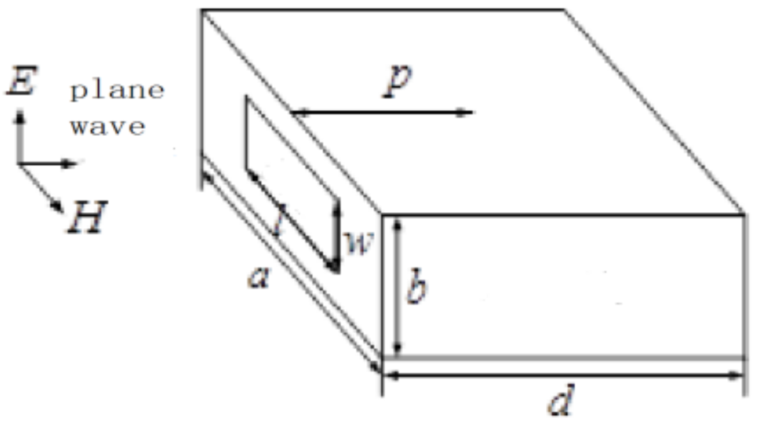
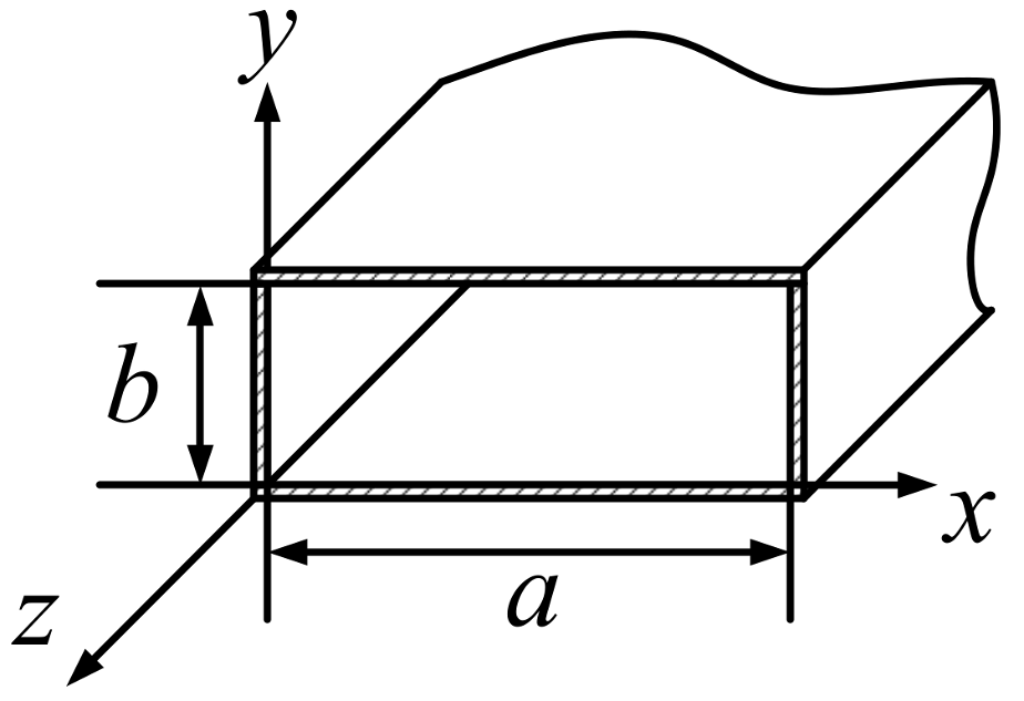
2. Shielding Effectiveness of Single Side Aperture Cavities

According to the theoretical model of the transmission line established by Robinson et al. [7], when a plane wave is vertically irradiated as a shielded cavity (as shown in Figure 1), the equivalent circuit model shown in Figure 2 can be obtained.
The incident plane wave excitation is equivalent to the voltage V 0 and the impedance Z 0 of the equivalent voltage source. The aperture in the cavity wall is equivalent to a coplanar strip line, according to Gupta’s theory [14], and the effective width of the aperture w e < b / 2 ; the aperture characteristic impedance is
Z a p = 1 2 C Z 0 s ( Z L + j Z 0 s tan ( k 0 l / 2 ) ) / Z 0 s + j Z L tan ( k 0 l / 2 )
in which Z L is the surface impedance of the cavity wall. If the wall material is a good conductor, its impedance is zero. When the aperture is not in the center of the cavity wall, the influence of different aperture positions on the coupling effect can be calculated by introducing the parameters [10] as follows:
C = x 0 x 0 + l y 0 y 0 + w sin ( π x / a ) cos ( π ( x x 0 ) / l ) d x d y / X Y
in which X and Y are the distance coordinates from the coordinate origin to the center of the aperture, as shown in Figure 3.
When the cavity is equivalent to the rectangular waveguide with a short terminal in the TE10 mode, the waveguide characteristic impedance and propagation constant are Z g = Z 0 / 1 ( λ / 2 a ) 2 and k g = k 0 1 ( λ / 2 a ) 2 , in which k 0 = 2 π / λ . Then, the equivalent voltage V p and the equivalent impedance Z p of the observation point P ( p x , p y , p z ) can be deduced from the equivalent Thevenin’s theorem. If there is no shield, the load impedance of P is Z 0 ; then, the voltage is V p = V 0 / 2 , which can be obtained from the cavity shielding effectiveness as follows:
S E = 20 lg 10 | V p / V p | = 20 lg 10 | 2 V p / V 0 |

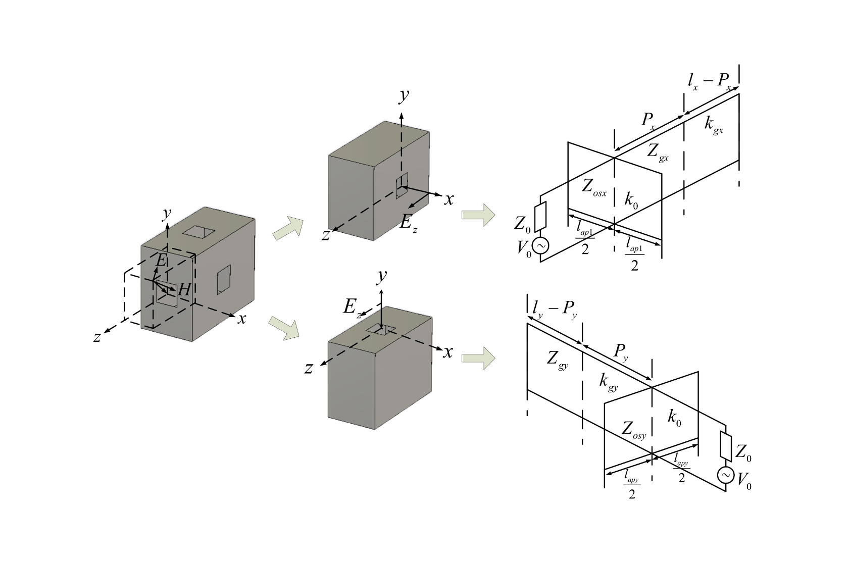
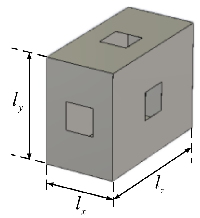
3. Multi-Sided Aperture Cavity Equivalent Transmission Line Extension Model

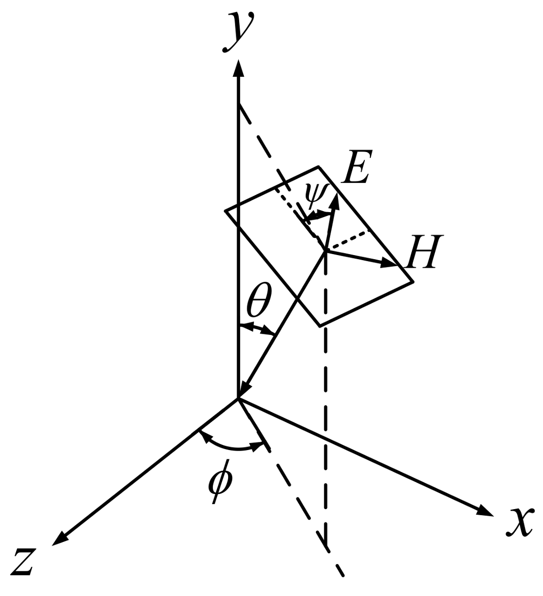
3.1. Vector Analysis of the Coupling Effect

As the aperture cavities are shown on different faces, the electromagnetic waves can be coupled with the cavity through the coupling of the apertures on the different faces. The equivalent transmission line method is equivalent to the excitation source. According to the field strength at the aperture, the direction of the incident wave is arbitrary, so the field strength of different faces are different. Therefore, it is necessary to vectorize the incident wave to obtain the field strength of the different surface seams. As shown in Figure 4, according to the azimuth angle ϕ , the pitch angle θ , and the polarization angle ψ of the incident plane wave, the components of the three different directions x, y, and z [15] are shown as
E = x ^ ( cos ϕ sin ψ sin ϕ cos θ cos ψ ) E 0 + y ^ ( sin θ cos ψ ) E 0 + z ^ ( cos ϕ cos θ cos ψ sin ϕ sin ψ ) E 0 = x ^ F p x E 0 + y ^ F p y E 0 + z ^ F p z E 0
in which E 0 is the effective value of E , and F p x , F p y and F p z represent the three directional components of the field strength coefficient (x, y and z). The decomposition of the propagation constants β is as follows:
β = x ^ ( sin ϕ sin θ ) β 0 + y ^ ( cos θ ) β 0 + z ^ ( cos ϕ sin θ ) β 0 = x ^ F i x β 0 + y ^ F i y β 0 + z ^ F i z β 0
in which β 0 is the effective value of β , and F i x , F i y and F i z represent the three directional propagation parameters (x, y, and z, respectively).
As shown in Figure 5, the incident wave can be connected to the cavity through the apertures in different faces. On the basis of the above-mentioned vector decomposition, the coupling of the incident wave to the cavity was decomposed into six problems that were analyzed separately. Where the x direction of the incident wave component can produce the y and z directions of the field strength, the y direction of the incident wave component can produce the x and z directions of the field strength, and the z direction of the incident wave component can produce the x and y directions of the field strength in the cavity.
Although the traditional equivalent transmission line method can only calculate the shielding effect on the center line of the cavity, the important components of the electronic equipment, such as the integrated circuit board, are not necessarily on the center line of the cavity. Therefore, the equivalent transmission line method needs to be improved so that it can calculate the shielding effectiveness of any position within the cavity.
According to the equivalent transmission line method, when calculating the coupling effect of the z-directional incident wave component on a multi-sided cavity, the open-aperture cavity can be equivalent to the rectangular waveguide shown in Figure 6. When the TE-mode wave is propagated in the waveguide, the field intensity distribution at any position is
E x = ( j ω μ n π / k c 2 b ) H m n cos ( m π x / a ) sin ( n π y / b ) e j ( w t β z ) E y = ( j ω μ m π / k c 2 a ) H m n sin ( m π x / a ) cos ( n π y / b ) e j ( w t β z ) , E z = 0
When the TM wave is propagated in the rectangular waveguide, the field intensity distribution at any position in the cavity is
{ E x = ( j β m π / k c 2 a ) E m n cos ( m π x / a ) sin ( n π y / b ) e j ( w t β z ) E y = ( j β n π / k c 2 b ) E m n sin ( m π x / a ) cos ( n π y / b ) e j ( w t β z ) E z = E m n sin ( m π x / a ) sin ( n π y / b ) e j ( w t β z )
In order to solve the field strength of the non-centerline position in the cavity, it is necessary to extract the position parameters representing in the y direction field strength in different modes:
F T E , T M = sin m π x / a ) cos ( n π y / b )
Substituting Equation (8) for the calculation of the equivalent transmission line masking effect, the shielding effectiveness of any position in the cavity can be calculated.

3.2. The Calculation Model of the Shielding Effectiveness

The vector analysis of the incident wave can be calculated for different incident wave components of the aperture coupling effect. This results in the following aspects of the cavity in the direction of the shielding effectiveness of a specific analysis. As shown in Figure 7, the z direction of the cavity is in the direction of the x O z surface of the aperture and the y O z surface of the aperture, coupling with the cavity. Because the electromagnetic waves through the x O y surface of the aperture couples with the cavity in the z direction, and because it does not produce strong energy, it is negligible. When the incident wave is coupled with the cavity from the y O z surface, the aperture is equivalent to the coplanar strip line with a length of l a p x and a characteristic impedance of Z o s x . The cavity is equivalent to a waveguide with a length of l x and an impedance of Z g x , in which Z g x is mainly determined by the cavity sizes l y , l z , and the waveguide mode. After obtaining the above parameters, we can obtain the shielding effectiveness of P, which is p x distance from the aperture.
The equivalent transmission line method can be seen in the incident wave component of the aperture under the equivalent width:
w e x = w a p x 5 t / 4 π ( 1 + ln ( 4 π w a p x / t )
in which w a p x is the width of aperture and t is the thickness of the cavity wall. The characteristic impedance of the aperture is as follows:
Z o s x = 120 π 2 [ ln ( 2 ( 1 + 1 ( w e x / l z ) 2 4 ) / ( 1 1 ( w e x / l z ) 2 4 ) ) ] 1
The equivalent impedance of the aperture is corrected according to the relationship between the size of the aperture and the size of the cavity:
Z a p x = 1 2 C m Z o s x × ( Z l + j Z o s x tan ( k 0 l a p x / 2 ) ) × ( Z o s x + j Z l tan ( k 0 l a p x / 2 ) ) × n a p x
The characteristic impedance and propagation constant of the waveguide in different transmission modes are given by the following equation:
Z g x = Z 0 / 1 ( n λ / 2 l y ) 2 ( l λ / 2 l z ) 2 ;   k g x = k 0 1 ( n λ / 2 l y ) 2 ( l λ / 2 l z ) 2
in which n is the y direction of the mode wavenumber and l is the z direction of the mode wavenumber. In combination with the above Z 0 , V 0 , and Z a p , the aperture coupling of the electromagnetic wave to the cavity is equivalent to the excitation of the voltage source including the resistance and voltage to the transmission line, given by the following equation:
V 1 x = V 0 Z a p x / ( Z 0 + Z a p x ) ;   Z 1 x = Z 0 Z 0 + Z a p x / ( Z 0 + Z a p x )
As the coordinates at the observation point P are ( p x , p y , p z ) , the equivalent voltage and equivalent impedance of P are as follows:
Z 2 x = ( Z 1 x + j Z g x tan k g x p x ) / ( 1 + j ( Z 1 x / Z g x ) tan k g x p x ) V 2 x = V 1 x / ( cos k g x p x + j ( Z 1 x / Z g x ) sin k g x p x ) Z 3 x = j Z g x tan k g x ( l x p x )
Finally, the voltage of P is given by the following equation:
V T E x = V 2 x Z 3 x / ( Z 2 x + Z 3 x )
V T E x is considered as the sum of the different TE modes, multiplied by the incident parameters F p z , the propagation parameters F i x , and the position parameters F T E z x , as shown below:
V T E z x = n l F p z F i x F T E z x V T E x ( n , l )
Similarly, when the incident wave is coupled into the cavity from the x O z surface, the aperture is equivalent to a coplanar strip line with a length of l a p y and a characteristic impedance of Z o s y . The cavity is then equivalent to a waveguide with a length of l y and an impedance of Z g y . Similarly, can be derived in the T E ( m , l ) mode, which is determined by m and l. Then, by introducing the polarization parameter F p z , the incident parameter F i y , and the position parameter F T E z y , V T E z y can be obtained as follows:
V T E z y = m l F p z F i y F T E z y v T E y ( m , l )
By adding V T E z x to V T E z y , we can calculate the equivalent voltage at the P position and in the z direction, which is the incident wave coupling into the cavity through the different surface apertures:
V T E z = V T E z x + V T E z y
Similarly, the equivalent voltage V T M z in the TM mode can be obtained. Then, the total equivalent voltage of point P in the cavity is as follows:
V z = V T E z + V T M z
The same approach can be used for the equivalent voltage solution at the observation point in the x and y directions, and, finally, the total voltage can be obtained by the vector overlapped of the different directions of the equivalent voltage:
V t o t a l = | V x | 2 + | V y | 2 + | V z | 2
According to the calculation formula of shielding efficiency, this voltage is converted into a shielding efficiency expression as shown below:
S E t o t a l = 20 log | V t o t a l / ( V 0 / 2 ) |

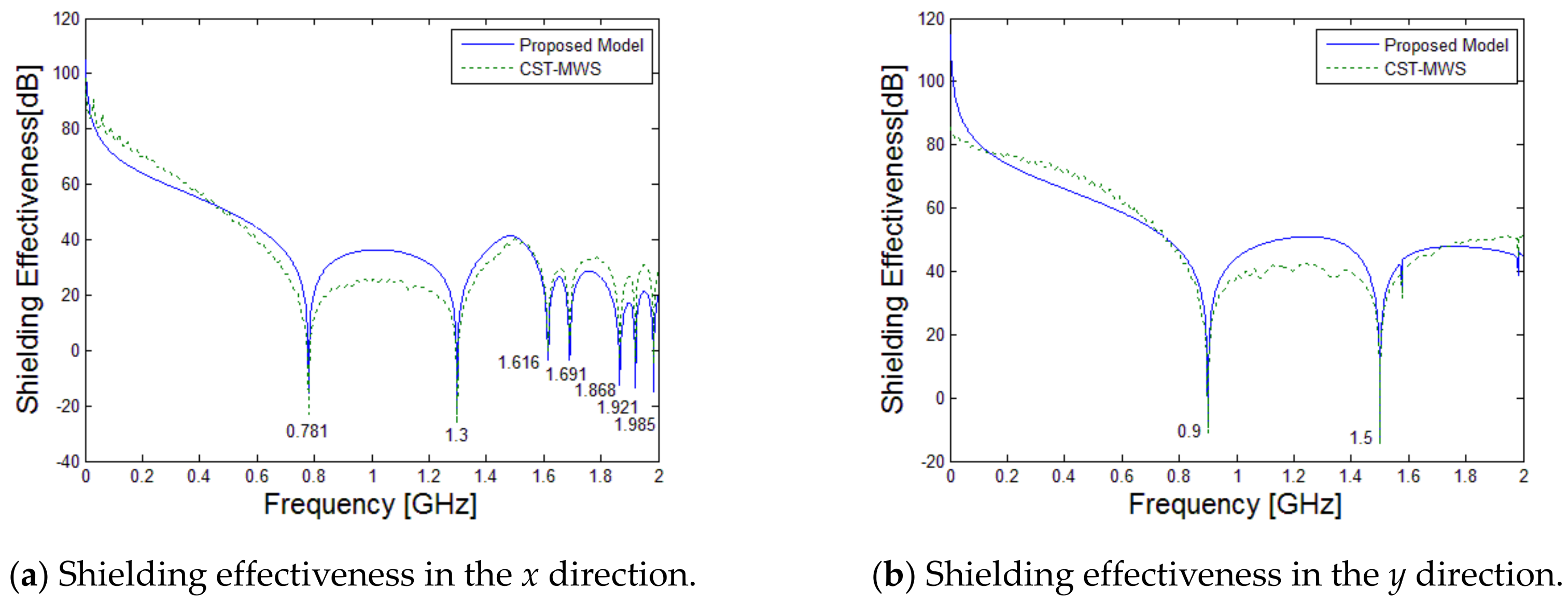
4. Model Verification

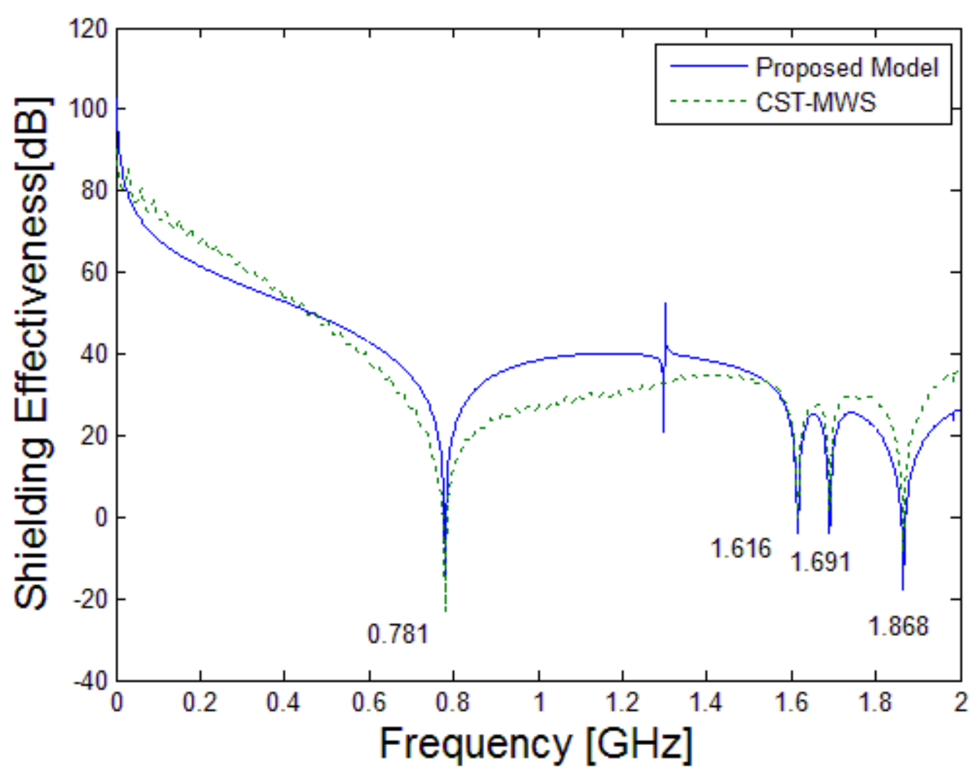
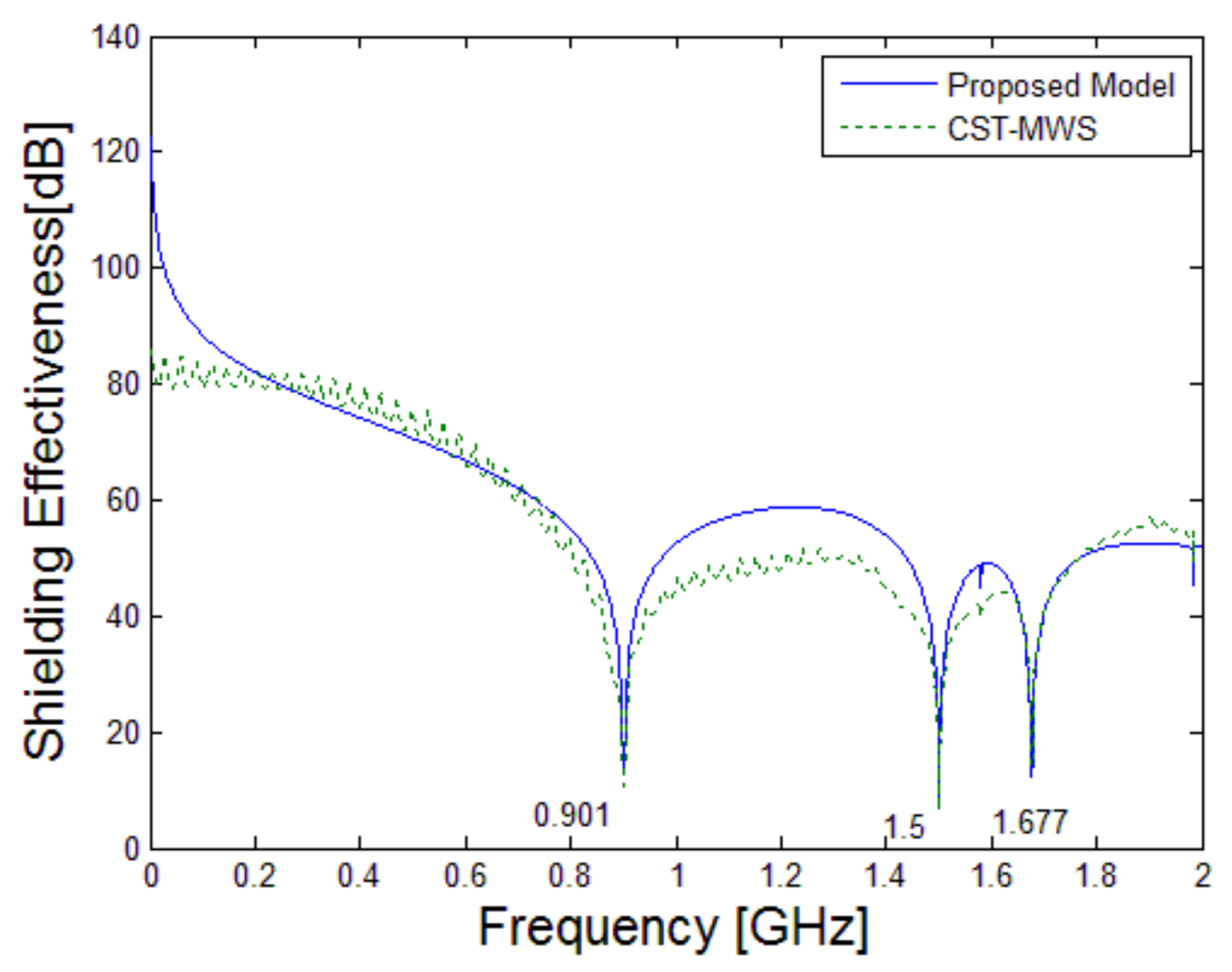
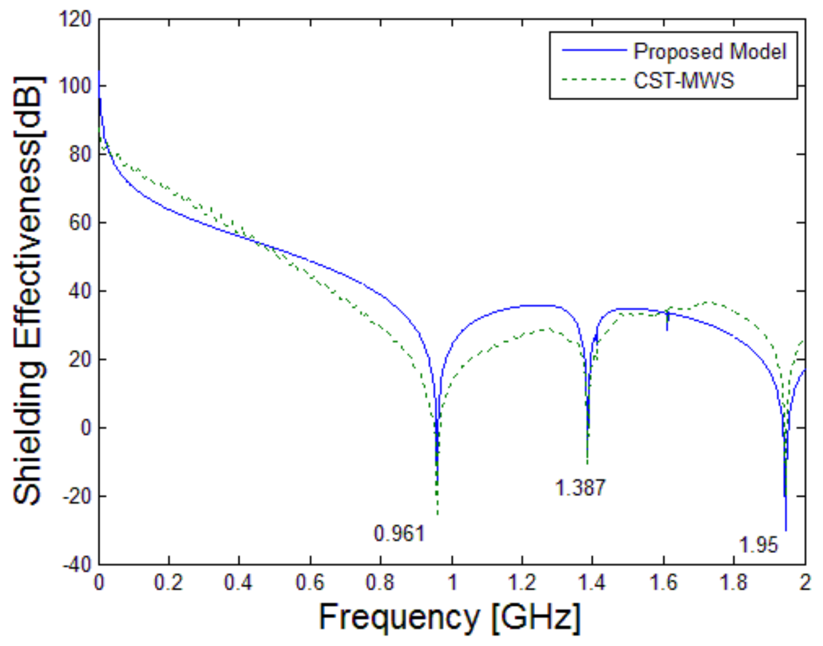
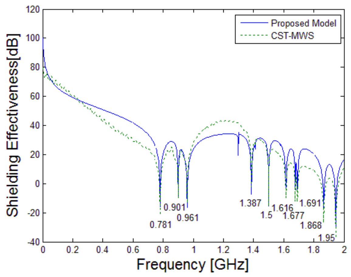
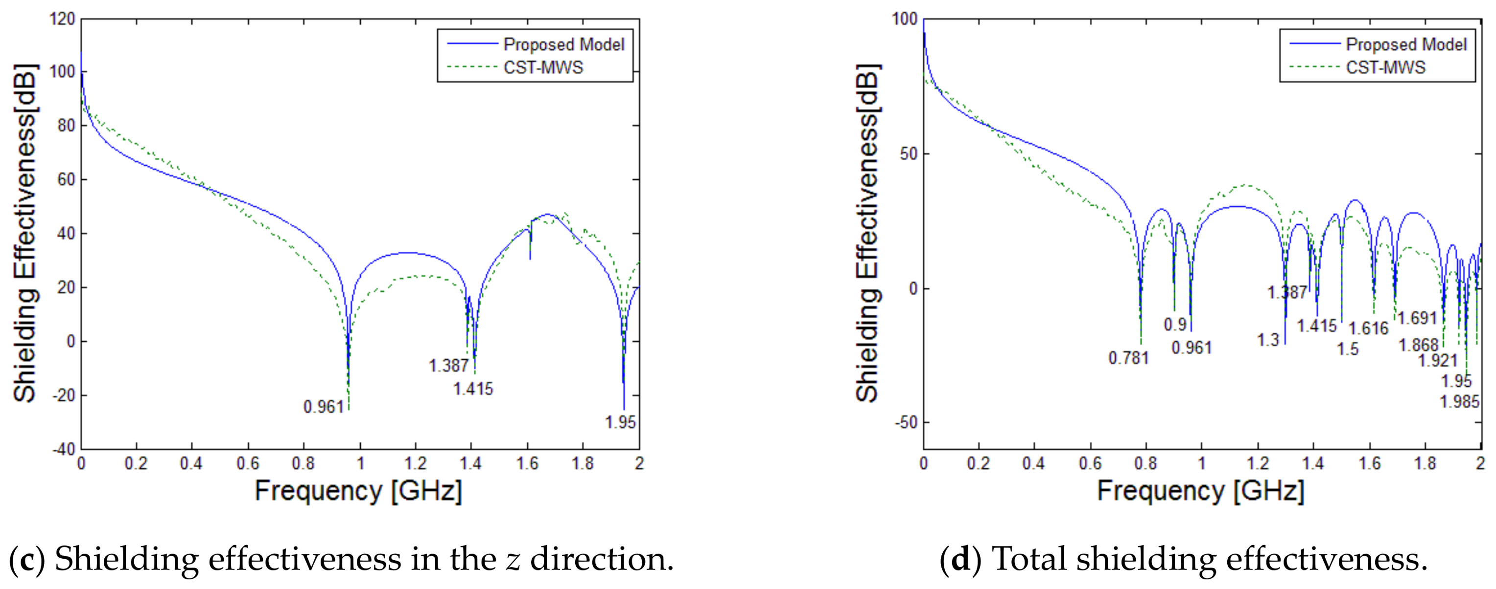
4.1. Cavity Center Point Shielding Effectiveness Verification

Figure 8 shows a rectangular cavity with a length of 20 cm, a width of 25 cm, a height of 30 cm, a wall thickness of 1 mm, and a square aperture of 7 cm × 7 cm. The simulation conditions are a plane wave with a pitch angle of θ = π / 4 , an azimuth angle of ψ = π / 4 , a polarization angle of ϕ = π / 4 , an electric field intensity of E = 10 V/m, and linear polarization. Using the proposed method in this paper and CST simulation software (CST, Frankfurt, Germany), we calculated the center of the cavity in the frequency range of 0–2 GHz and observed that the shielding effectiveness changes.
Figure 9 shows the shielding effectiveness of the center of the cavity in the x direction. The solid line in the figure shows the results of the improved equivalent transmission line method, while the dotted line represents the CST simulation results. The figure shows that the results of this method and the CST simulation results are basically consistent.
According to Equation (22), the resonant frequency in the x direction in the cavity was calculated, and the x direction resonant frequency values that are shown in Table 1 were obtained. Since the P point is the center point of the cavity, n and l are odd whilst only m is even. The extreme point of the field strength distribution is exactly at the center point of the lower chamber, as shown in Figure 10. Although the field strength distribution in the cavity is different at different resonant frequencies, the extreme value of the field strength distribution point is always at the center of the cavity. According to the calculations, in the frequency range of 0–2 GHz, the cavity has four resonant frequencies that totally meet the above conditions. In Table 1, red numbers show the resonant frequencies, which match the results of this paper and once again prove the correctness of this model.
f m n l = c k m n l / 2 π μ r ε r = c ( m π / l x ) 2 + ( n π / l y ) 2 + ( l π / l z ) 2 / 2 π μ r ε r
The following results show the shielding effectiveness in the y direction at the center of the cavity. Figure 11 and Table 2 show that the results obtained from the improved equivalent transmission line method are in good agreement with the CST simulation results. The frequency of the minimum shielding effectiveness in the y direction at the center of the cavity is almost the same as the theoretical resonant frequencies shown in Table 2, requiring an even n and an odd m and l.
The following results show the shielding effectiveness in the z direction at the center of the cavity. Figure 12 and Table 3 show that the results obtained from the improved equivalent transmission line method are in good agreement with the CST simulation results. The frequency of the minimum shielding effectiveness in the z direction at the center of the cavity is almost the same as the theoretical resonant frequency shown in Table 3, requiring an even n and an odd m and l.
Figure 13 shows the total shielding effectiveness at the center of the cavity. It can be seen that the results obtained from the equivalent transmission line method are in good agreement with the CST simulation results. The frequency of the minimum shielding effectiveness at the center point of the cavity matches the theoretical resonant frequency in each direction shown in Table 1, Table 2 and Table 3, respectively, which proves the correctness of the improved equivalent transmission line method.

4.2. Model Verification of the Shielding Effectivenesses at Any Position in the Cavity

The calculation of the shielding effectiveness at any position in the cavity is simulated below. The observation point P is in p x = 8 cm, p y = 15 cm, and p z = 20 cm, and the simulation results are obtained by using the improved equivalent transmission line method and CST, respectively.
Figure 14 shows the results of the different shielding effectivenesses of different directions at any point in the cavity. The solid line shows the results obtained by using the improved equivalent transmission line method, and the dotted line represents the results obtained using the CST simulation software. These figures show that the results obtained from the transmission line method are in good agreement with the CST simulation results. In this case, since the observation point is not the center of the cavity, the field intensity distribution in other modes will affect the shielding effectiveness. Thus, the shielding effectiveness of the point P is smaller than that of the center point.

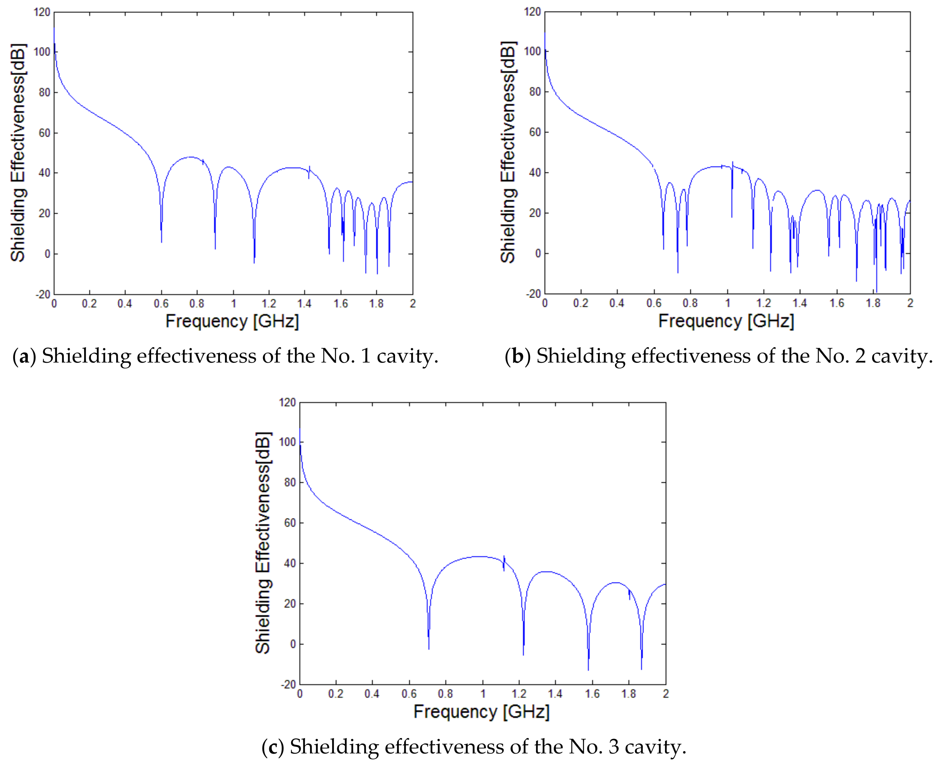
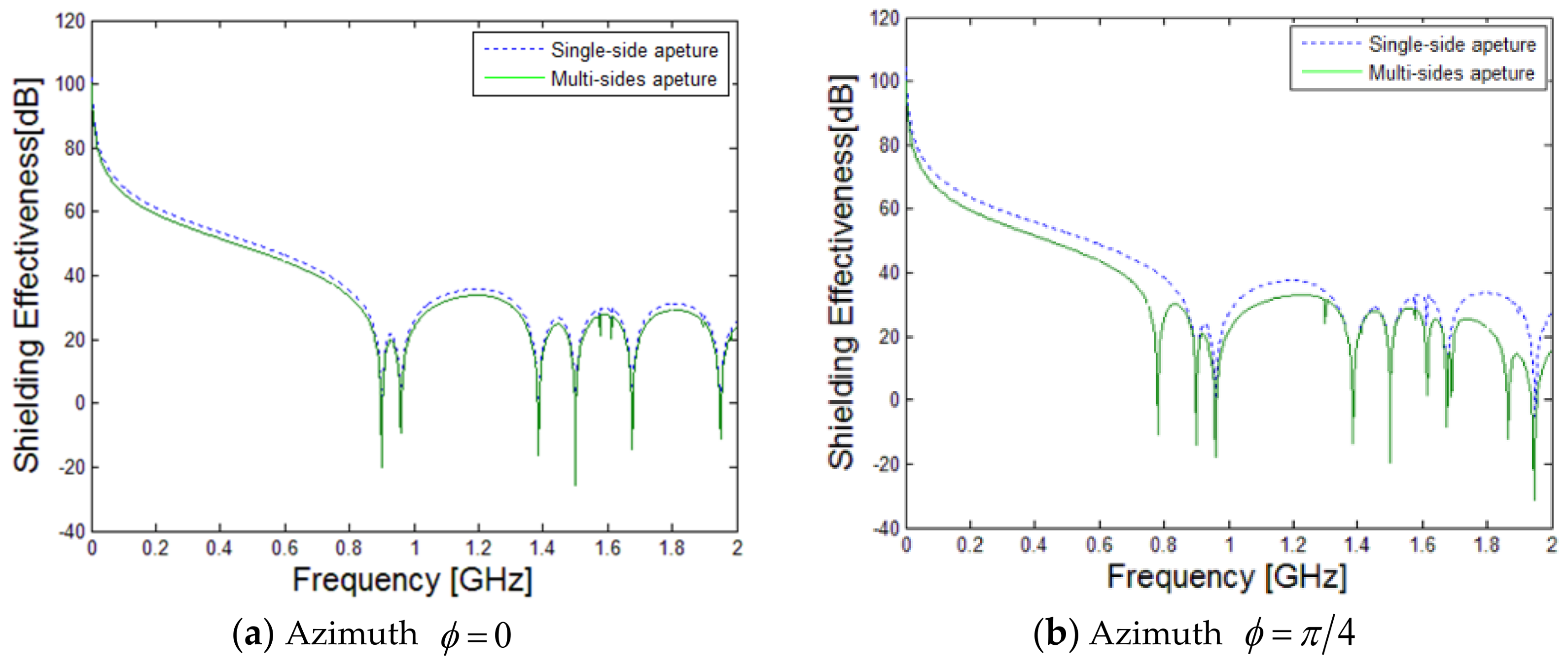
5. Analysis of the Shielding Effectiveness of a Multi-Sided Aperture Cavity

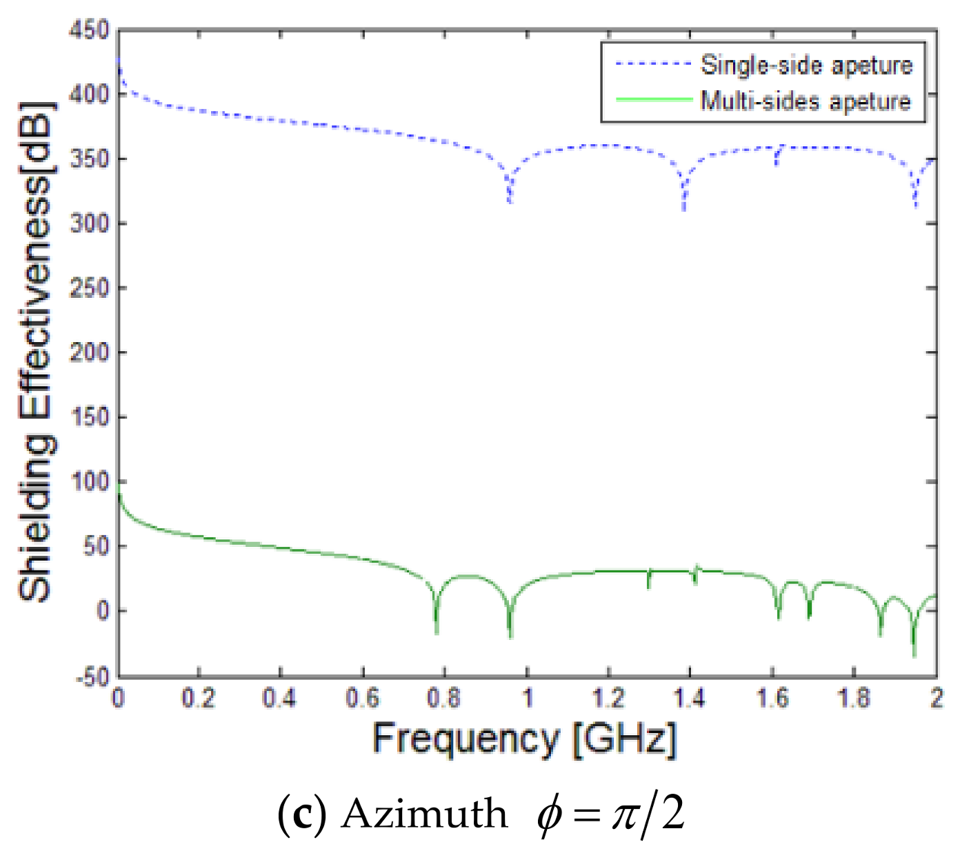
5.1. Influence of the Azimuth Angle of the Incident Wave on the Shielding Effectiveness

By maintaining the cavity size, the aperture size will be unchanged whilst the incident wave pitch angle θ = π / 2 , polarization angle ψ = π / 4 , and azimuth ϕ change constantly. The three azimuths under the single side aperture are ϕ = 0 , ϕ = π / 4 , and ϕ = π / 2 .
It can be seen from Figure 15 that the effects of different azimuth angles on the single sided aperture cavity and the three-sided aperture cavity are different. When the azimuth angle is equal to zero, the shielding effectivenesses of the two are basically the same. When the azimuth angle is equal to π / 4 , due to the presence of the other two faces on the multi-sided cavity, the overall shielding effectiveness is weaker than that of the single side aperture cavity, which brings about an increase of the number of minimum values in the shielding effectiveness t. This is because of the other two sides of the aperture, which are of different directions of the field strength component, resulting in an increase in the cavity field strength component at the center of the cavity. When the azimuth angle is equal to ϕ = π / 2 , there is quite a difference in the shielding effectivenesses. The shielding effectiveness of the single-sided aperture cavity is very high, between 300 dB and 425 dB, because it has been shielded from electromagnetic interference. The shielding effectiveness of the multi-sided aperture cavity is between −50 dB and 100 dB, because the incident wave illuminates the cavity from the side under the aforementioned azimuth angle, as the multi-sided aperture cavity has an aperture under the aperture referred to above.

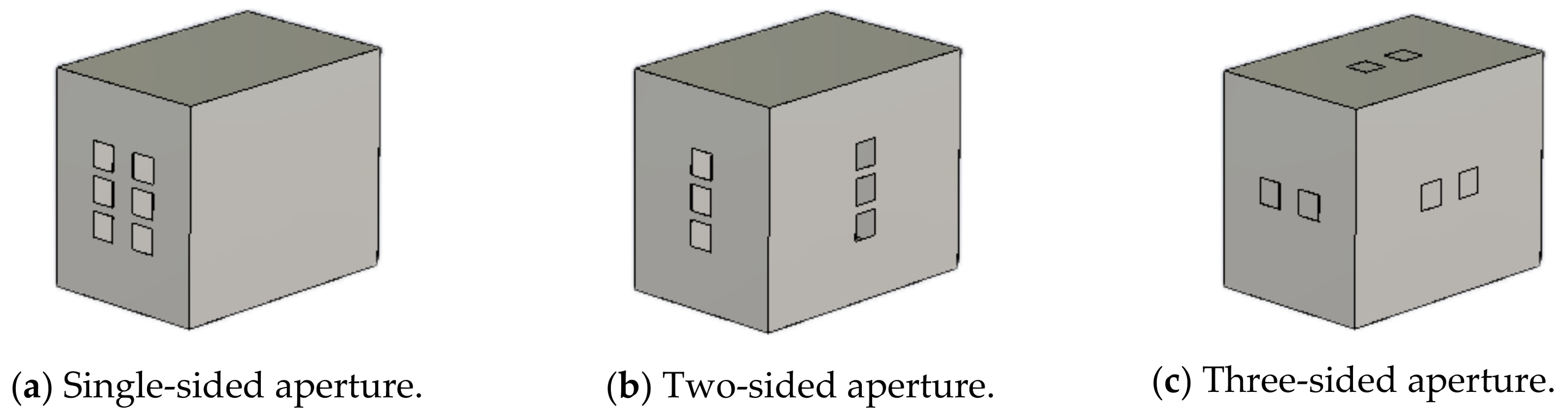
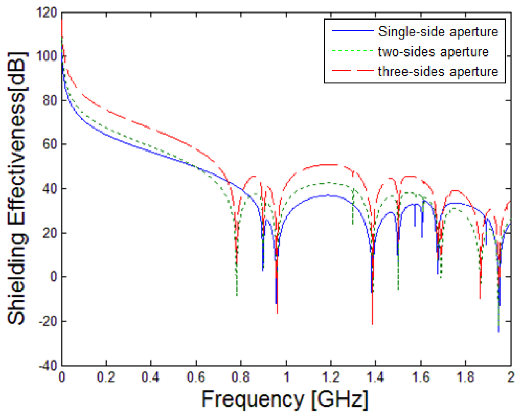
5.2. Influence of the Number of Apertures on the Shielding Effectiveness

If the cavity size and the total area of the aperture array remain unchanged, the aperture of the cavity form is divided into single-sided, two-sided, and three-sided apertures (all the aperture sizes are 1.5 cm × 1.5 cm). The shielding effectiveness of the multi-sided apertures show in Figure 16 using the improved transmission line method is shown in Figure 17. If the total aperture area is kept constant, the multi-sided apertures can enhance the shielding effectiveness of the cavity, but the multi-sided apertures will produce the extra shielding effectiveness at the minimum point, thereby increasing the probability of electronic equipment interference. It can also be seen from the figure that the number of shielding effectiveness minima of the two-sided and three-sided apertures are the same, because the x direction of the incident wave component can produce a field strength in the y and z directions of the cavity that are the same as the y and z directions of the incident wave component. Therefore, only two different sides of the aperture can be generated in the cavity in three directions of field strength. It is thus possible to effectively enhance the shielding effectiveness of the cavity by sewing the aperture on different sides, which would create additional minima points of the shielding effectiveness. Therefore, different aperture forms should be selected according to the characteristics of the electronic equipment.

5.3. Influence of Cavity Size on the Shield Effectiveness

If the cavity volume is 0.009 cubic meters, the incident wave elevation angle, the azimuth angle, and the polarization angle are θ = π / 4 ; the field strength is 10 V/m; the size of the No. 1 cavity, the No. 2 cavity, and the No. 3 cavity are 30 cm × 45 cm × 20 cm, 30 cm × 36 cm × 25 cm, and 30 cm × 30 cm × 30 cm; and all the apertures are 3 cm × 3 cm squares. Using the improved method of equivalent transmission lines, the shielding effectiveness of the different cavities of Figure 18 are shown in Figure 19. The shielding effectivenesses of the three cavities is the same, with minimum points of shielding effectiveness between −20 dB and 20 dB. Compared with the No. 1 cavity and the No. 2 cavity, the No.3 cavity has fewer minimum points of the shielding effectiveness. This is because it is a square, and the resonant frequency of the cavity in different directions is consistent, resulting in a decrease in the minimum point of the shielding effectiveness graph. It can be concluded that under the same volume, the size of the cavity is set to a square. Although it cannot increase the shielding effect, it can reduce the shielding efficiency minimum point. Therefore, it will reduce the probability that electronic devices are subject to electromagnetic interference.

6. Conclusions

In this paper, the shielding effectiveness of a multi-sided aperture cavity is studied and analyzed, and the defects of the equivalent transmission line method are improved to calculate the coupling effect of the incident wave on the multi-sided aperture cavity. The results of the equivalent transmission line method and the results obtained from the CST simulation software and the cavity resonant frequency are compared to verify the correctness of the method. The influence of the angle of incidence, the number of openings, and the size of the cavity on the coupling effect were analyzed by using the improved equivalent transmission line method. The results showed that any incident angle can produce a coupling effect, because of the presence of multi-sided apertures in multi-sided cavities. In the case of having the same aperture area, the multi-sided aperture can effectively enhance the shielding effectiveness of the cavity but will produce an additional shielding effectiveness for the minimum point. In the case of having the same volume, the shielding effectiveness of the cube is basically the same as that of the cuboid but is the minimum point of the shielding effectiveness of the cube lessens.

Author Contributions

Tao Hu and Jinjin Wei built up the model; Dan Chen and Xulai Chen simulated the model, Farnaz Foroughian and Lingyu Ren analyzed the data.

Conflicts of Interest

The authors declare no conflict of interest.

References

  1. Shanghe, L.; Weidong, L. Progress of relevant research on electromagnetic compatibility and electromagnetic protection. High Volt. Eng. 2014, 40, 1605–1613. [Google Scholar]
  2. Kai, L.; Guanghui, W.; Xiaodong, P.A.N. Research of the shielding effectiveness of a rectangular metallic enclosure with an aperture. J. Microw. 2013, 29, 48–52. [Google Scholar]
  3. Wallyn, W.; De Zutter, D.; Laermans, E. Fast shielding effectiveness prediction for realistic rectangular enclosures. IEEE Trans. Electromagn. Compat. 2003, 40, 639–643. [Google Scholar] [CrossRef]
  4. Nie, B.L.; Du, P.A.; Yu, Y.T.; Shi, Z. Study of the shielding properties of enclosures with apertures at higher frequencies using the transmission line modeling method. IEEE Trans. Electromagn. Compat. 2011, 53, 73–81. [Google Scholar] [CrossRef]
  5. Shi, D.; Shen, Y.; Ruan, F.; Wei, Z.; Gao, Y. Shielding analysis of enclosure with aperture irradiated by plane wave with arbitrary incident angle and polarization direction. In Proceedings of the IEEE International Symposium on Electromagnetic Compatibility, Detroit, MI, USA, 18–22 August 2008; pp. 1–5. [Google Scholar]
  6. Belkacem, F.T.; Bensetti, M.; Boutar, A.G.; Moussaoui, D.; Djennah, M.; Mazari, B. Combined model for shielding effectiveness estimation of a metallic enclosure with apertures. IET Sci. Meas. Technol. 2011, 5, 88–95. [Google Scholar] [CrossRef]
  7. Robinson, M.P.; Benson, T.M.; Christopoulos, C.; Dawson, J.F.; Ganley, M.D.; Marvin, A.C.; Porter, S.J.; Thomas, D.W. Analytical formulation for the shielding effectiveness of enclosures with apertures. IEEE Trans. Electromagn. Compat. 1998, 40, 240–248. [Google Scholar] [CrossRef]
  8. Belokour, I.; LoVetri, J.; Kashyap, S. A higher-order mode transmission line model of the shielding effectiveness of enclosures with apertures. In Proceedings of the IEEE International Symposium on Electromagnetic Compatibility, Montreal, QC, Canada, 13–17 August 2001; pp. 702–707. [Google Scholar]
  9. Azaro, R.; Caorsi, S.; Donelli, M.; Gragnani, G.L. A circuital approach to evaluating the electromagnetic field on rectangular apertures backed by rectangular cavities. IEEE Trans. Microw. Theory Tech. 2002, 50, 2259–2266. [Google Scholar] [CrossRef]
  10. Poad, F.; Jenu, M.Z.; Christopoulos, C.; Thomas, D.W.P. Multimode consideration in the analysis of shielding effectiveness of a metallic enclosure with off-centred apertures. In Proceedings of the International RF and Microwave Conference, Putra Jaya, Malaysia, 12–14 September 2006; pp. 306–310. [Google Scholar]
  11. Dehkhoda, P.; Tavakoli, A.; Moini, R. An efficient and reliable shielding effectiveness evaluation of a rectangular enclosure with numerous apertures. IEEE Trans. Electromagn. Compat. 2008, 50, 208–212. [Google Scholar] [CrossRef]
  12. Han, S.; Jie, C.; Yinggang, L. Analysis of Shielding Effectiveness in Double Layer Rectangular Enclosure with Aperture by Higher-order Mode Transmission Line Method. High Volt. Eng. 2009, 4, 877–883. [Google Scholar]
  13. Qiang, P.; Dongfang, Z.; Deting, H.; Daojie, Y.; Tao, H.; Liping, W.; Wei, X. Shielding effectiveness analysis of rectangular cavity with aperture by modi-fication and expansion of transmission line method. High Power Laser Part. Beams 2013, 25, 2355–2362. [Google Scholar] [CrossRef]
  14. Gupta, K.C.; Garg, R.; Bahl, I.J. Microstrip Lines and Slotlines; Artech House: Boston, MA, USA, 1996. [Google Scholar]
  15. Jongjoo, S.; Gun, K.D.; Hwa, K.J. Circuital Modeling and Measurement of Shielding Effectiveness Against Oblique Incident Plane Wave on Apertures in Multiple Sides of Rectangular Enclosure. IEEE Trans. Electromagn. Compat. 2010, 3, 566–577. [Google Scholar]
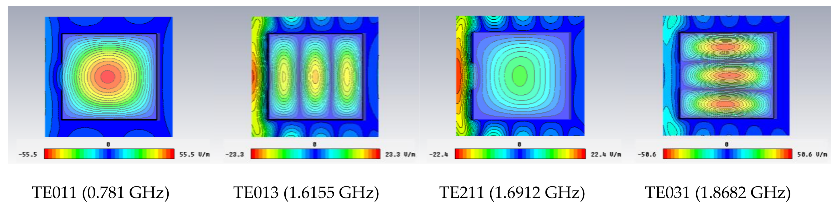
Figure 1. The cavity with an aperture. a, b and d are the length, height, and width of the rectangular cavity, respectively. l and w are the length and width of the gap, respectively.
Electronics 07 00052 g001
Figure 2. The equivalent circuit model.
Electronics 07 00052 g002
Figure 3. The aperture coordinate diagram.
Electronics 07 00052 g003
Figure 4. Vector analysis of the incident electromagnetic wave.
Electronics 07 00052 g004
Figure 5. The coupling model of the incident wave to the cavity.
Electronics 07 00052 g005
Figure 6. The equivalent rectangular waveguide.
Electronics 07 00052 g006
Figure 7. The equivalent circuit diagram in the z direction.
Electronics 07 00052 g007
Figure 8. The multi-sided aperture cavities.
Electronics 07 00052 g008
Figure 9. The shielding effectiveness in the x direction.
Electronics 07 00052 g009
Figure 10. The field distribution of the cavity under different resonant frequencies.
Electronics 07 00052 g010
Figure 11. The shielding effectiveness in the y direction.
Electronics 07 00052 g011
Figure 12. The shielding effectiveness in the z direction.
Electronics 07 00052 g012
Figure 13. The total shielding effectiveness at the center of the cavity.
Electronics 07 00052 g013
Figure 14. The total shielding effectiveness of the position ( p x = 8 cm, p y = 15 cm, and p z = 20 cm) in the cavity.
Electronics 07 00052 g014aElectronics 07 00052 g014b
Figure 15. The shielding effectiveness of different azimuths.
Electronics 07 00052 g015aElectronics 07 00052 g015b
Figure 16. The multi-sided apertures.
Electronics 07 00052 g016
Figure 17. The shielding effectivenesses of the multi-sided apertures.
Electronics 07 00052 g017
Figure 18. The different sizes of cavities.
Electronics 07 00052 g018
Figure 19. The shielding effectiveness of different sizes of cavities.
Electronics 07 00052 g019
Table 1. The resonant frequencies in the x direction. The red numbers show the resonant frequencies that match the results of this paper.
l = 1l = 3
m\n0123m\n0123
00.50000.78101.30001.868201.51.61551.92092.3431
10.90141.08281.50082.013111.67711.78122.06222.4602
21.58111.69121.98492.3958
Table 2. The resonant frequencies in the y direction. The red numbers show the resonant frequencies that match the results of this paper.
l = 1l = 3
m\n0123m\n0123
00.50000.7811.30001.868201.51.61551.92092.3431
10.90141.08281.50082.013111.67711.78122.06222.4602
21.58111.69121.98492.3958
Table 3. The resonant frequencies in the z direction. The red numbers show the resonant frequencies that match the results of this paper.
l = 0l = 2
m\n123m\n123
10.96051.41511.9511.38651.73282.1915
21.61551.92092.343121.92.16562.5475

