Stand-Alone Microgrid Inverter Controller Design for Nonlinear, Unbalanced Load with Output Transformer

1
Department of Control and Instrumentation Engineering, Korea University of Transportation, Chungju 27469, Korea
2
QIT Co., Ltd. #402, Acegwanggyotower1, Daehak 4-ro 17, Yeongtong-gu, Suwon-si 162262, Gyeonggi-do, Korea
*
Author to whom correspondence should be addressed.
Electronics 2018, 7(4), 55; https://doi.org/10.3390/electronics7040055
Submission received: 22 March 2018
/
Revised: 20 April 2018
/
Accepted: 20 April 2018
/
Published: 23 April 2018
(This article belongs to the Special Issue Renewable Electric Energy Systems)
Abstract
:This paper proposes a technique that compensates for unbalance and nonlinearity in microgrid inverters with power transformers operating in stand-alone mode. When a microgrid inverter is operating in stand-alone mode, providing high-quality power is very important. When an unbalanced, nonlinear load is connected, zero sequence current and negative sequence current occur, which leads to an unbalanced output voltage. This paper examines why the zero sequence component occurs differently depending on the structure of a three-phase transformer connected to the inverter output terminal, and it proposes a method for controlling the zero sequence component. It also uses a resonant controller to remove the harmonics that correspond to the negative sequence component and the nonlinear component. The proposed elements were verified by a Powersim (PSIM) simulation.
1. Introduction
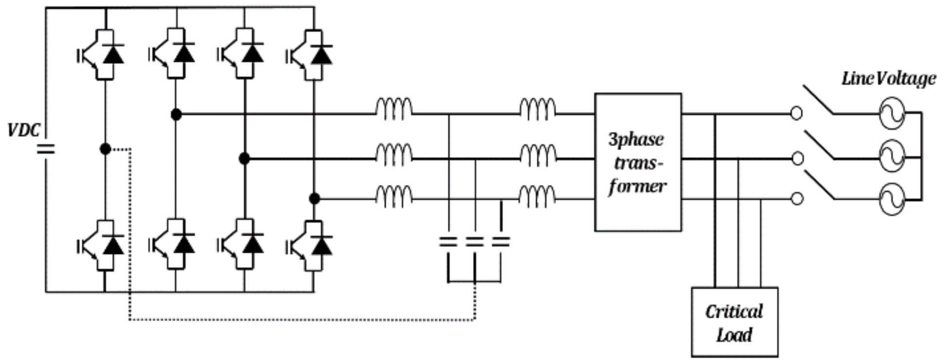
A microgrid is a small-scale stand-alone electrical grid. It acts as a next-generation electrical system that combines renewable energy such as solar or wind power with an energy storage system [1,2]. A microgrid inverter is one of the elements that make up the overall system, and it operates in a grid-connected mode or a stand-alone mode. When operating in grid-connected mode, it acts as a current source. If a grid disturbance or fault occurs, a static switch is opened, and it changes to stand-alone mode. In stand-alone mode, the microgrid inverter is in charge of the entire demand load as the sole voltage source. Therefore, it is important to supply reliable power to the load when operating in stand-alone mode [3,4,5,6]. Figure 1 shows the structure of a microgrid inverter, which has a 3-phase inverter, filter, and static switch.
If an unbalanced load is connected to the microgrid inverter’s output side, unbalance occurs in the current of each phase. So, unbalance occurs in the output voltage. These kinds of unbalanced components can be decomposed by the Symmetrical Coordinates Method into a positive sequence component that has the same magnitude and a positive sequence phase shift, a negative sequence component that has the same magnitude and a negative sequence phase shift, and a zero sequence component that has the same magnitude and phase [7,8]. To create a balanced voltage, the unbalanced components, i.e., the zero sequence component and the negative sequence component, must be removed.
On the other hand, the microgrid inverter is designed to have a three-phase transformer at the output stage for the user’s safety and common mode noise reduction in some applications. Since the zero sequence component has the same magnitude and phase at each phase, it occurs differently depending on the structure of the transformer. Three-phase, four-wire inverters for removing the zero sequence component and negative sequence component have been studied [9,10,11,12,13], but these studies do not address the zero sequence component impedance caused by the transformer structure. There have also been studies on the zero sequence component impedance caused by the transformer structure in electric power distribution systems [14,15,16], but there have been no previous studies on stand-alone inverters.
Phase shorts and ground faults often occur when electrical energy is being transmitted. In a microgrid inverter system, when a phase fault or ground fault occurs, the fault must be detected quickly on the microgrid inverter. However, when a three-limb core transformer is used that does not have a zero sequence component flux path, the secondary-side zero sequence component by the phase shorts and ground faults is not transmitted to the primary side, so problems occur due to fault detection failure. On the other hand, if a five-limb core-type transformer is used that has a zero sequence component flux path, the secondary-side zero sequence component can be entirely transmitted to the primary side. Although the fault current can be detected without any problem, the transmitted zero sequence component creates a large voltage unbalance under normal load unbalance conditions, so additional control techniques are required. If an unbalanced load is connected to the output terminal of a microgrid inverter with five-limb core-type transformer in stand-alone mode, unbalance occurs in the output voltage. In order to prevent a voltage unbalance in the inverter’s output terminal, the negative sequence component and zero sequence component must be controlled. It is possible to control the negative sequence component and zero sequence component if the current unbalance occurring at the transformer’s secondary side is transferred through the transformer to the inverter. However, the previous papers [9,10,11,12,13] discussing micro inverters do not address the issue of controlling zero sequence components caused by the structure of the transformer. Furthermore, a three-phase diode rectifier that turns AC voltage into DC voltage is the most common nonlinear load in microgrid systems. If nonlinear loads such as a three-phase diode rectifier are connected to a stand-alone inverter, 6n − 1 and 6n + 1 harmonics are created in each phase. Because of these harmonics, the supplied voltage by the inverter has harmonic distortion. To resolve this, there have been studies on proportional-resonant controllers that have control commands for both higher harmonics and fundamental harmonics. A proportional-resonant controller can be used to remove the harmonic components, but this has a disadvantage in that there must be compensation for both 6n − 1 and 6n + 1 harmonics [17,18,19,20,21] in the stationary reference frame.
This paper proposes a stand-alone microgrid inverter design technique that compensates for both unbalanced and nonlinear components for five-limb-type transformer systems in the synchronous reference frame. The control method in the synchronous reference frame is simple, because there are only 6n harmonics to be compensated, compared with the stationary frame, in which there are both 6n − 1 and 6n + 1 harmonics. In Section 2, zero sequence components caused by the transformer structure are analyzed in Section 2.1, and their effect on the output voltage described. A control technique for the zero sequence component is proposed in Section 2.2, for the negative sequence component in Section 2.3, and for nonlinearity with a five-limb transformer in a synchronous reference frame in Section 2.4. In Section 2.5, the full system of the proposed controller is described. In Section 3, a Powersim (PSIM) simulation analysis is performed for the proposed technique, and its effectiveness is evaluated.
2. Stand-Alone Inverter Design Considering Output Transformer
2.1. Changes in Zero Sequence Component According to Transformer Structure
In the general magnetic circuit design of a three-phase transformer shown in Figure 2a, there is a three-limb core type, in which the tops and bottoms of three vertical parallel limbs are connected by a horizontal yoke. Another type of three-phase transformer has a five-limb core structure that includes three limbs with coiled windings and two limbs with uncoiled windings, as shown in Figure 2b. In a three-phase transformer made of three single-phase transformers, the impedance of the positive sequence component, negative sequence component, and zero sequence component are the same, the unbalanced component appears equally on the primary and secondary sides of the transformer like a balanced component. However, in the case of a three-phase transformer, the positive sequence component and zero sequence component react differently, depending on the connection type and the core structure.
The zero sequence current of the microgrid inverter is the sum of each phase’s current, as shown in (1):
where, is the current of a, b and c phase, and is the sum of the zero sequence currents. is the zero sequence currents in each phase. The zero sequence current shows the third harmonic of the fundamental harmonic, and the magnitude and phase () are the same in each phase. If the three phases are balanced, the zero sequence current is zero, but if they are unbalanced, the zero sequence current is not zero.
Figure 3a shows the zero-sequence-component magnetic flux of a three-limb core-type transformer. The magnitude and direction of the zero-sequence-component magnetic flux of each phase is the same, so it does not disappear, but appears as three times the zero sequence component, which is the sum of each component. This tripled zero-sequence-component magnetic flux flows along a path through air or oil outside the transformer. Since this path has a large amount of magnetic resistance, a large amount of magneto motive force occurs. As a result, the load-side zero sequence component is controlled by the transformer. Problems occur, such as an increased transformer temperature and an increased loss [14]. On the primary side, which has capacitors that determine the output voltage, the zero sequence component is not transmitted, so a zero-sequence-component voltage does not occur on the primary side. In addition, when short circuits and ground faults occur and a three-limb core-type transformer is being used, the secondary-side zero sequence component is not transmitted to the primary side, so a problem occurs, in that the failure cannot be detected by the zero sequence current. Figure 3b shows the zero-sequence-component magnetic flux of a five-limb core-type transformer. Five-limb core-type transformers provide a path through which the zero-sequence-component magnetic flux can pass. Therefore, the zero sequence component flows through the transformer’s core, which has low magnetic resistance, and the load-side zero sequence component is transmitted entirely to the primary side. The zero sequence current is transmitted to the primary-side capacitor owing to the load-side zero sequence component, and unbalance occurs in the output voltage.
2.2. Zero-Sequence-Component Control Technique in a Five-Limb Core-Type Transformer
When a three-limb core-type transformer is used, the zero sequence component created by the unbalanced load is not transferred to the primary side. Therefore, it is impossible to perform zero sequence current control at the inverter. However, when a five-limb core-type transformer is used, the load-side zero sequence current is transmitted to the primary side, so zero sequence current control is possible, and an additional control technique can be applied to control the zero sequence current.
Equation (2) converts the stationary coordinate frame variables for each phase into a synchronous reference frame.
where are functions of phase a, b, and c. is transformation matrix of abc frame to synchronous coordinate frame. represents the d,q,0 axis of the synchronous coordinate frame. is the 0-axis of the synchronous coordinate frame [22,23]. In (2), the zero sequence component is shown on the synchronous reference frame’s 0-axis (). Therefore, to remove the zero sequence component, we must use the dq0 control, which controls up to the 0-axis in the existing dq controller.
Figure 4 shows a three-phase, four-wire inverter with output transformer. It is a structure in which two switches that connect to the neutral terminal are added to the six existing switches, and 0-axis control commands generated by Equation (2) are used to control the switches connected to the neutral wire and to control the zero sequence component.
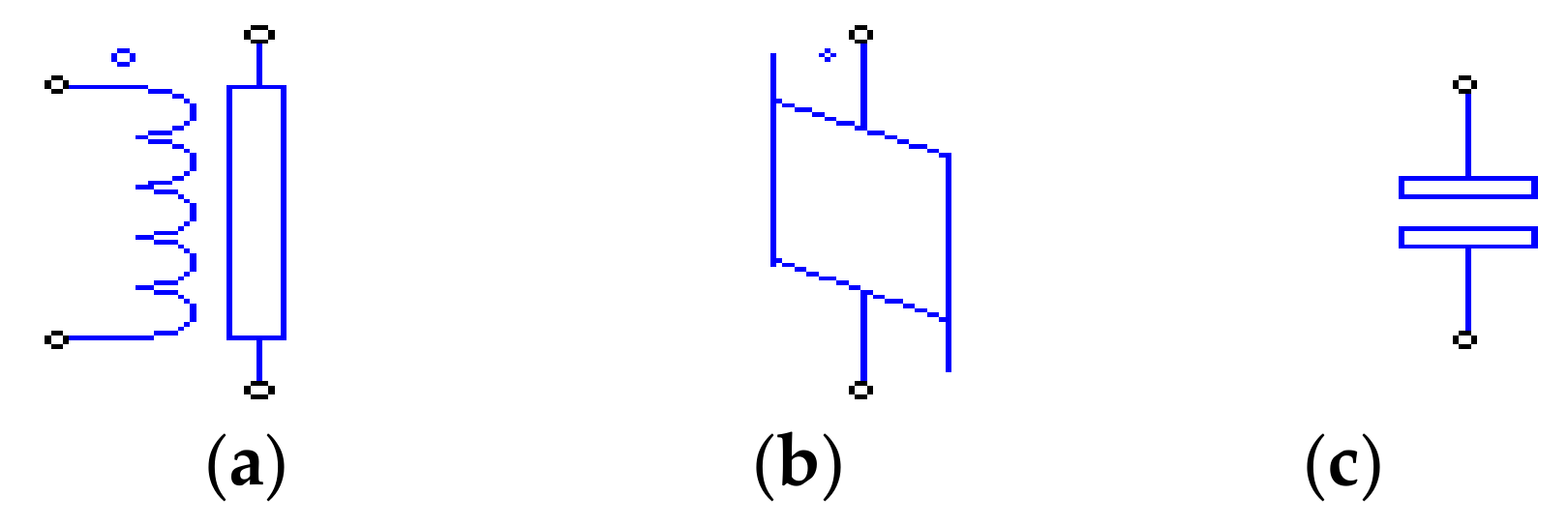
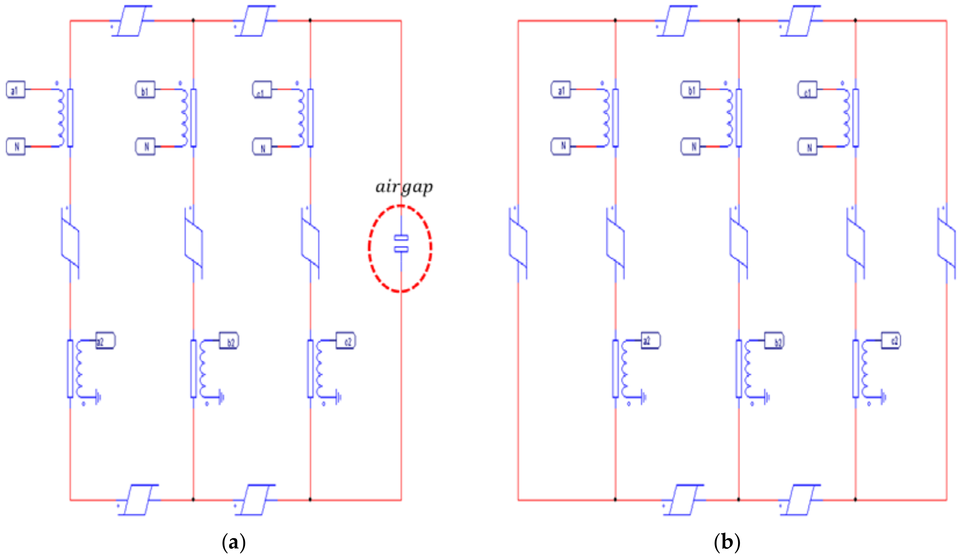
A simulation analysis of the transformer, which has zero-sequence-component magnetic transfer properties, was performed using the winding, linear core, and the air gap within the PSIM’s magnetic element [24]. Figure 5 shows the PSIM’s magnetic element device. Figure 5a shows the winding element, which converts electric energy to magnetic energy. The winding element is the same coil. Figure 5b is a linear core, it can simulate magnetic flux according to magnetoresistance. Figure 5c is airgap, and it represents the magnetic flux flowing through air. Figure 6 shows an equivalent circuit of transformers implemented via PSIM software. Figure 6a shows a three-limb core-type transformer in which the tops and bottoms of three vertical parallel limbs are connected by a horizontal yoke. The zero sequence component has the same magnitude and phase in each phase. In a three-limb core-type transformer, since there is no path connecting the top and bottom of the transformer for the zero sequence component to flow, zero sequence component flux flows through the airgap outside the transformer. Figure 6b shows a five-limb core-type transformer. In a five-limb core-type transformer, zero sequence component flux flows through the extra two linear cores.
The three-phase inverter circuit in Figure 7 was designed, and a simulation analysis was performed for the changes in the output voltage according to the transformer structure under unbalanced load conditions (Ra = 20 Ω, Rb = 12 Ω, and Rc = 200 Ω). Labels a1, a2, b1, b2, c1, c2 of simulation are connected to the equivalent model of the transformer shown in Figure 6a or Figure 6b.
Figure 8 shows the simulation results of the output voltage and output current in which a three-limb core-type transformer is used, and an unbalanced load is connected. Output voltage () has a small unbalance. If a three-limb core-type transformer is used, the zero sequence component that occurs from the load flows through the air gap, which has a high magnetic resistance. Therefore, the zero sequence component is not transmitted smoothly to the primary side, and only the positive sequence component and negative sequence component appear on the primary side. In the simulation results, a 20-V voltage unbalance occurred owing to the negative sequence component. Even if this configuration has a small unbalance voltage, the phase short and ground faults cannot be detected by the high impedance for zero-sequence magnetic flux, which can be a big problem for the micro-grid system reliability.
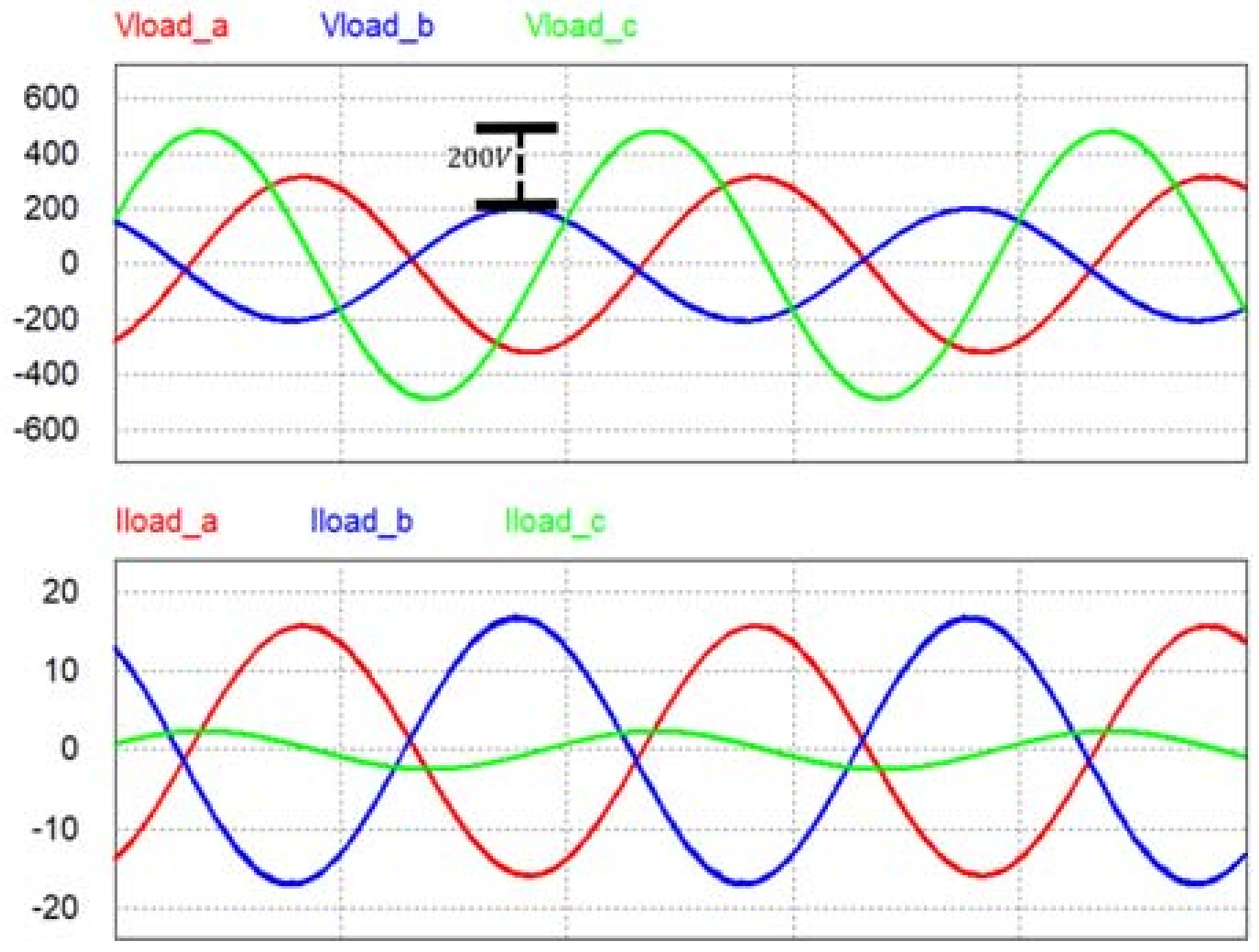
Figure 9 shows the simulation results of a simulation using a normal proportional-integral (PI) controller without zero-sequence-component compensation when a five-limb core-type transformer is used to detect the load’s short circuits and ground faults. The five-limb core-type transformer has a magnetic flux path that the zero sequence component can pass through, so the load’s zero sequence component is entirely transmitted to the primary side. Therefore, the positive sequence component, negative sequence component, and zero sequence component are all transmitted to the capacitor, and the load side’s voltage unbalance is transmitted to the primary side. Thus, a large voltage unbalance occurs. Based on the parameters used, a voltage unbalance of around 220 V occurred.
In the case of a three-limb core-type transformer, the zero sequence component can be removed without additional controls, but it flows through the transformer, which affects the transformer’s lifespan. In addition, grid faults such as short circuits and ground faults cannot be detected. On the other hand, the five-limb core-type transformer can detect grid faults, but the zero sequence component is transmitted to the primary side and a large unbalance occurs, so a zero-axis controller must be added.
Figure 10 shows the dq0 controller block diagram. Where, is the output voltage in the synchronous coordinate frame. is the reference of the output voltage in synchronous coordinate frame. A voltage controller consisting of a PI controller generates an inductor current reference using voltage error. is the inductor current in the synchronous coordinate frame, and is the reference of the inductor current in the synchronous coordinate frame. A current controller consisting of a PI controller generates the reference of duty. is the reference of feedback duty. is the feedforward component of 3 phase PWM inverter [11,12,13]. is the duty reference in each axis of the PWM inverter. A zero sequence controller that controls the zero sequence component is added to the dq controller that controls the positive sequence component, and the zero sequence component is controlled. To provide a balanced voltage, the zero-sequence-component voltage command must be 0. The zero-sequence voltage error in the 0-axis voltage controller is PI controlled, and zero-sequence current commands are created. The voltage controller’s output becomes a zero-sequence current command proportional to the magnitude of the current unbalance, and controls the zero sequence current.
2.3. Negative-Sequence-Component Control Technique
If a three-limb core-type transformer is used or a three-phase four-wire inverter with a five-limb core-type transformer is built, and a dq0 controller is used, the zero sequence component can be removed. However, the negative sequence component still remains and causes an output voltage unbalance. The negative sequence component reverses the order of the phases as in (3):
where, is the positive sequence component for the abc frame and is the negative sequence component for the abc frame. The Equations (4) and (5) for converting the negative sequence component to a synchronous reference frame are as follows:
where is the negative sequence component for the synchronous coordinates frame. As shown in (5), the negative sequence component appears as a second harmonic in the synchronous reference frame. Figure 11 shows a controller block diagram for an inverter with an added resonant controller for removing the negative sequence component.
Equation (6) is the transfer function of the PI + R controller, and the PI + R controller is the sum of the PI controller and the resonant controller.
where, is the proportional gain of the voltage controller and is the integral gain of the voltage controller, and is the resonant gain of the voltage controller. In the resonant controller transfer function of Equation (2), at a frequency of , the controller has an infinite gain. Therefore, by using the resonance controller, it is possible to remove the second harmonic present in the negative sequence component.
The proposed controller adds a resonant controller for the second harmonic in parallel, and can remove the negative sequence component. Figure 12 shows a Bode plot of a proportional-integral + resonant (PI + R) controller; it can be seen that there is a large gain in the second harmonic frequency [20,21].
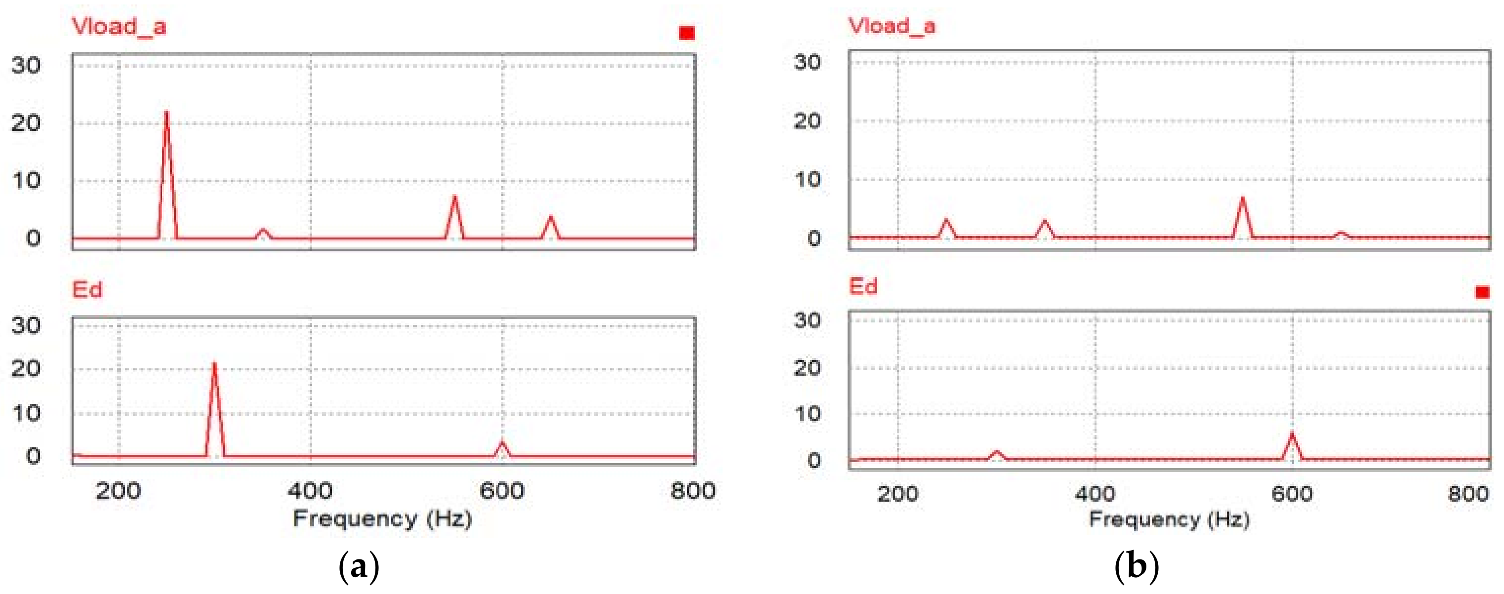
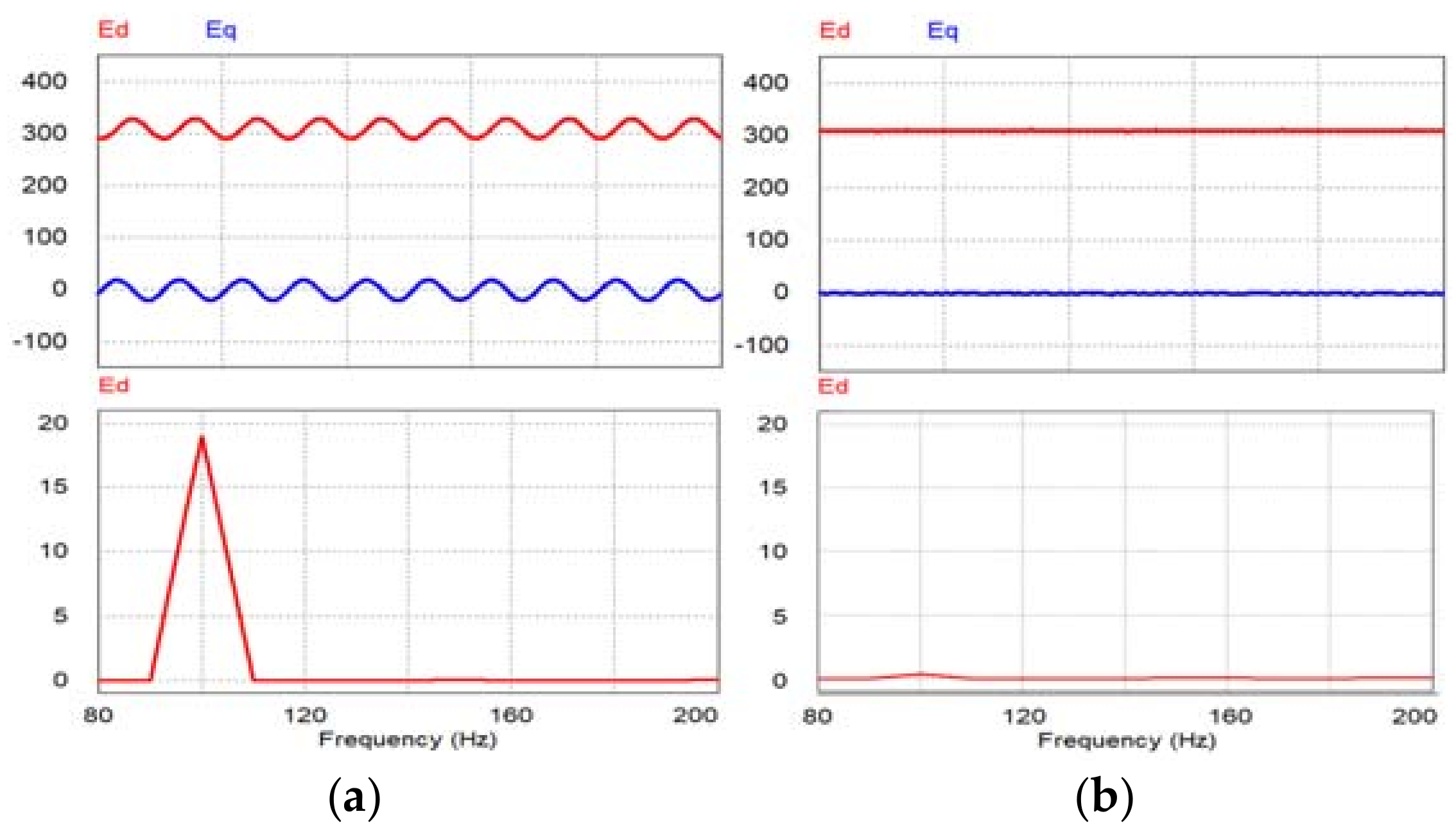
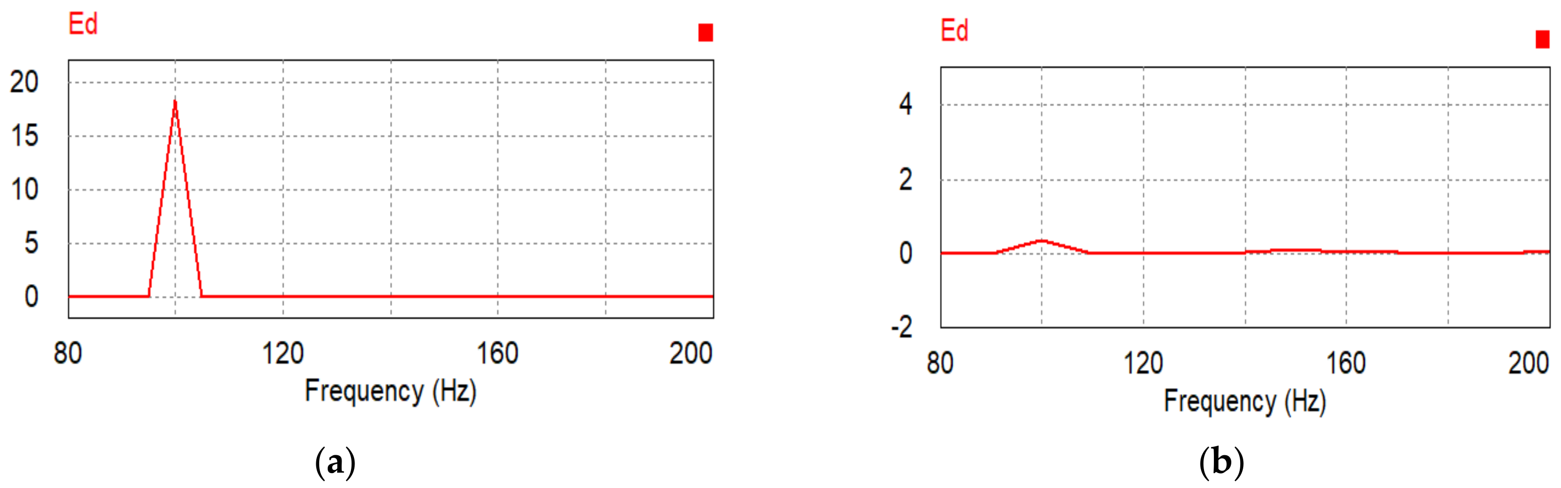
Figure 13 shows the results of a PSIM simulation in which a PI + R controller is used to control the negative sequence component. Under the same parameter conditions as Figure 7, a resonant controller was added in parallel to remove the secondary harmonic. The resonant controller removes the negative sequence component, so it can be seen that even when an unbalanced load is connected, a balanced voltage is produced. Figure 14 shows a fast Fourier transform (FFT) analysis. If a conventional PI controller (Figure 14a) is used, the negative sequence component appears as a second harmonic in the synchronous reference frame. If the secondary-side harmonic is controlled by the resonant controller (Figure 14b), the negative sequence component is removed, and balanced voltage can be produced.
2.4. Nonlinear Compensation Using PI + MR Controller
To use a DC load, the electrical energy user changes the AC voltage into DC through a rectifier, such as a diode rectifier [25,26,27]. This kind of rectifier load creates a 6n harmonic on the load side, and 6n − 1, 6n + 1 harmonics on the phase side, owing to a nonlinear load. If the three-phase diode rectifier’s input phase current is described as a Fourier series, in can be written as
where is the input current of the diode rectifier. Equation (7) is converted to a synchronous reference frame.
where is the input current of the diode rectifier in the synchronous frame. As shown in (8), if the 6n harmonic is removed from the synchronous reference frame, this has the benefit of removing both the 6n − 1 and 6n + 1 harmonics that appear in the phase. The existing PI + R controller compensates for both the 6n − 1 and 6n + 1 harmonics in the stationary reference frame, so the frequencies that must be removed become twice as numerous.
Equation (9) is the transfer function of PI + MR controller for nonlinear load, which is the sum of PI controller and multi-resonant controller.
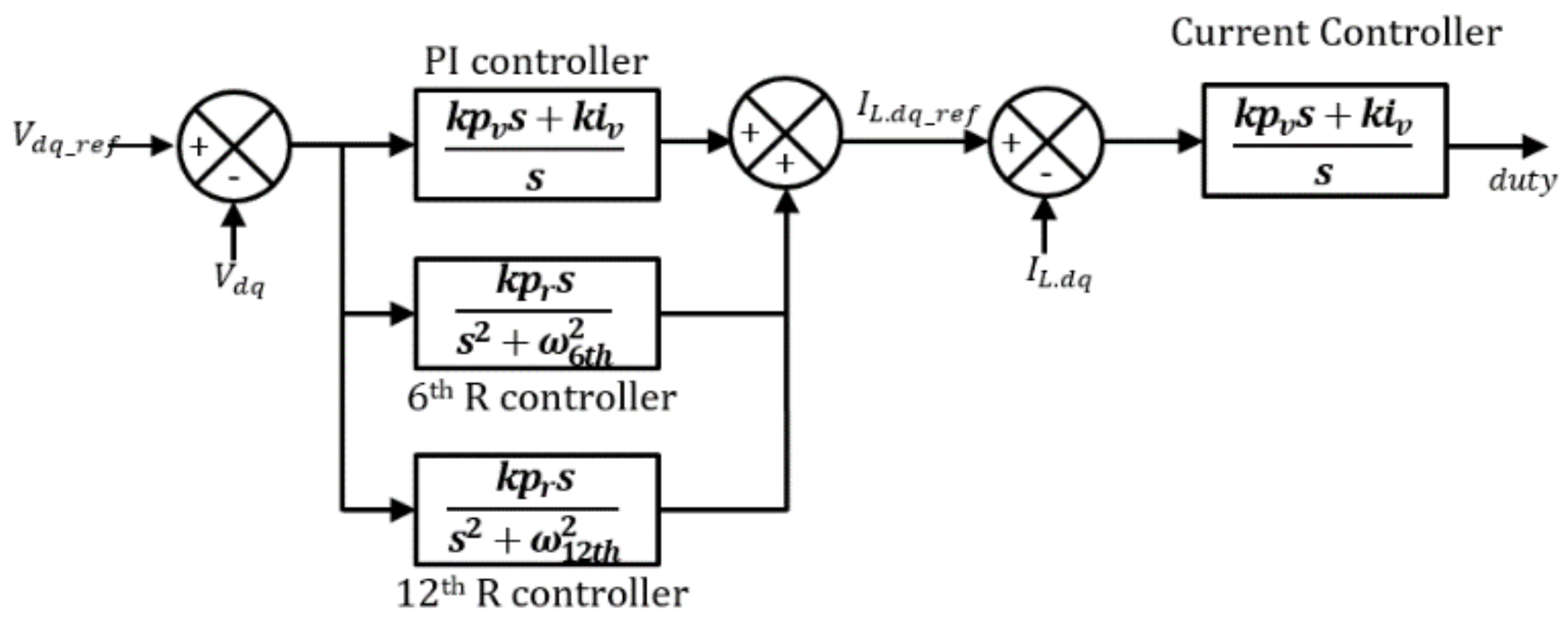
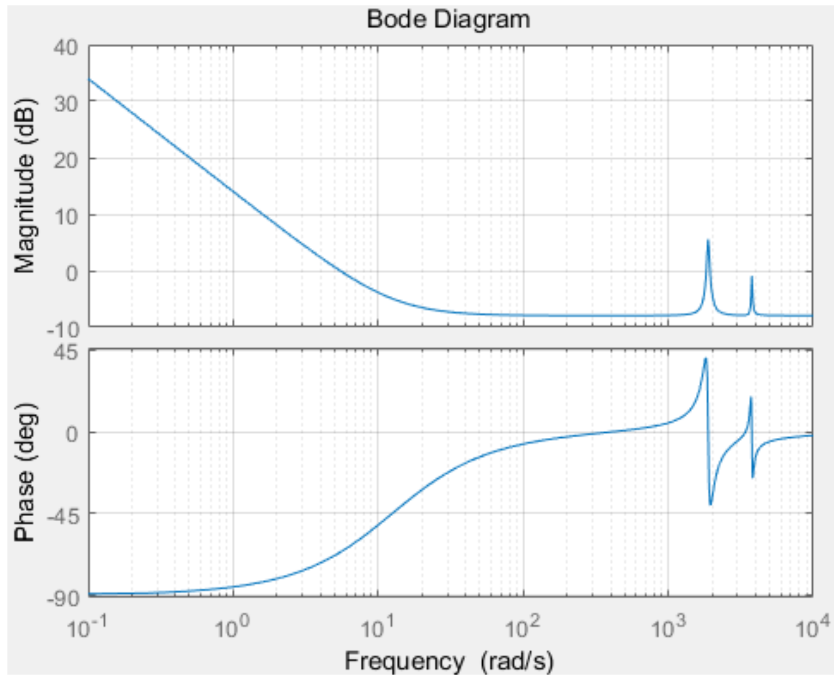
where is the resonant gain of 6th harmonic, is the radian of the 6th harmonic, is the resonant gain of the 12th harmonic, is the radian of the 12th harmonic. Figure 15 shows a block diagram of the resonant controller that controls the nonlinearity. The controller is designed to eliminate the 6th- and 12th-order components, which are the largest components of harmonics that make nonlinearity. Figure 16 shows a Bode plot of the resonant controller.
2.5. Microgrid Inverter Controller Design
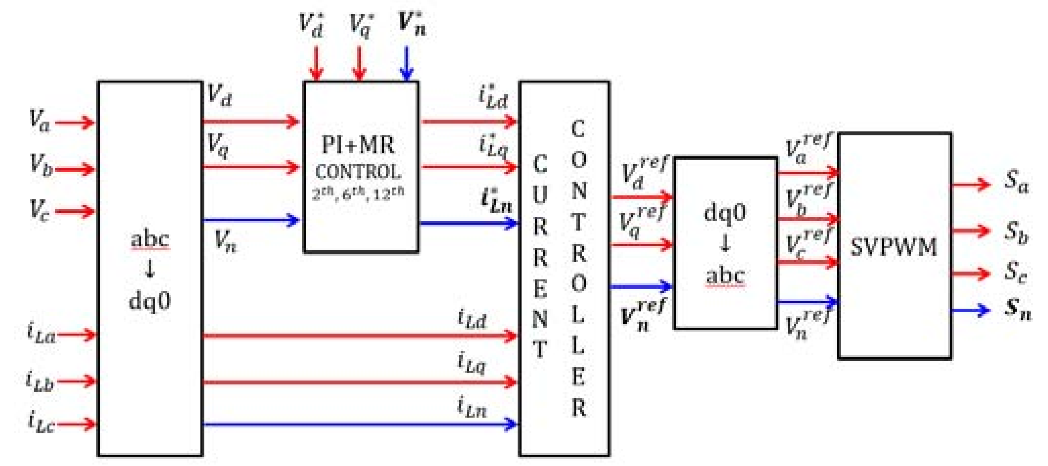
Based on the information above, a microgrid inverter was designed that can provide high-quality voltage when operating in stand-alone mode, even if an unbalanced load is connected. The inverter is a three-phase four-wire inverter that has a five-limb core-type transformer. Its controllers include a dq0 controller that controls the zero sequence component and a resonant controller that controls the negative sequence component and nonlinearity, as shown in Figure 17. The voltage controller generates the current command using the proposed PI + MR controller, and the current controller generates the duty command. The generated duty command controls the switch via the SVPWM. The overall controller Bode plot is shown in Figure 18. The Bode plot consists of a PI controller and resonance controller. In addition to the PI controller’s Bode plot, it shows a large gain at the frequency of the resonant controller.
3. Simulation
We applied the proposed control technique and simulated the output voltage that occurs when an unbalanced load and a nonlinear load are connected to a three-phase four-wire microgrid inverter. Table 1 lists the parameters used in the simulation.
Figure 8 shows the results of the simulation when a three-limb core-type transformer was used under unbalanced load conditions. Current unbalance occurs owing to the unbalanced load, but the current unbalance on the secondary side is not transmitted to the primary side owing to the three-limb core-type transformer, and the unbalance caused by the zero sequence component does not appear.
Figure 19a shows the results of employing a conventional PI controller when an unbalanced load is connected while using a five-limb core-type transformer. The five-limb core-type transformer can transmit the secondary-side zero sequence component to the primary side so that a large voltage unbalance occurs. Figure 19b shows the simulation results of output voltage and output current using a dq0 controller that compensates for the zero sequence component when a five-limb core-type transformer is connected. It has a three-phase four-wire inverter structure, and a zero-axis controller controls the two switches, which are connected to the neutral terminal to make the zero sequence component zero. The secondary-side zero sequence component is transmitted to the primary side, but the 0-axis controller controls the zero sequence voltage so that it is zero, and balanced voltage can be produced.
Figure 20 shows the results of simulations with and without a resonant controller to compensate for the negative sequence component when an unbalanced load is connected. Within a typical PI controller, negative sequence component isn’t removed and causes voltage unbalance. As a result of the simulation, as shown in Figure 20a, a voltage unbalance of about 20 V occurred. If a resonant controller is used to remove the second harmonic in which the negative sequence component appears, balanced voltage can be produced, as shown in Figure 20b. Figure 21 shows the results of an FFT analysis of the output voltage when the resonant controller is used and when it is not used. When the resonant controller is not used, the negative sequence component appears as a second harmonic in the synchronous reference frame, but if the resonant controller is used, the magnitude of the harmonic can be reduced.
Figure 22 shows the results of simulations with and without the resonant controller under nonlinear load conditions. As shown in the figure, the diode rectifier creates 6n − 1, 6n + 1 harmonics and causes the output voltage to be distorted. If a 6n resonant controller is used in the synchronous reference frame to compensate for this, the harmonics are removed, and a voltage that is close to a sine wave can be produced. Figure 23 shows the results of an FFT analysis of when the resonant controller is used and when it is not used under nonlinear load conditions. As shown in Figure 23a, the nonlinear load creates 6n ± 1 harmonics. Harmonics cause distortion of the output voltage. However, when the resonance controller is used, Figure 23b, resonance controller removes the 6n ± 1 harmonics. Hence, output voltage is clearer than using a conventional PI controller.
Table 2 shows the PSIM simulation results of the current and voltage THD(Total Harmonic Distortion). Using a conventional controller, the THD of the output voltage is 0.08. Using a resonant controller, the THD of the output voltage is 0.05, which is smaller than conventional controller.
4. Conclusions
In this paper, a technique for controlling unbalance and nonlinearity was developed, in which a microgrid inverter operates in stand-alone mode. The unbalance and nonlinearity that occur under various load conditions were differentiated, and compensation was performed for each of them. Study on the changes in the zero sequence component that occur as a result of the structure of a three-phase transformer was also carried out. If a three-limb core-type transformer is used, the zero sequence component can easily be removed from the circuit, but overheating and loss can occur in the transformer, and grid short circuits and ground faults cannot be detected at the microgrid inverter. On the other hand, when a five-limb core-type transformer is used to detect short circuits and ground faults, the zero sequence component is transmitted to the primary side, so output voltage unbalance occurs, owing to the zero sequence component. To resolve this, a 0-axis controller was added to control the zero sequence component and make it zero, and it was confirmed that power quality without unbalance could be produced even when unbalance occurred. The voltage unbalance caused by the zero sequence component appears as a second harmonic in the synchronous reference frame. A PI + R controller was designed to raise the gain of a frequency corresponding to the second harmonic and remove it. If a nonlinear load is connected, 6n − 1 and 6n + 1 harmonics occur in the phase, and if this is converted to a synchronous reference frame, a 6n harmonic occurs. Like the negative sequence component, the 6n component was removed by a resonant controller.
It is important for a microgrid inverter to produce high-quality power for a load when operating in stand-alone mode. In this paper, we studied the design of the microgrid inverter according to the transformer structure, which had not previously been considered. Since the zero sequence component changes depending on the structure of the transformer, a 5-limb core-type transformer should be used to detect the fault current on the primary side. The control technique for this problem was studied. If the proposed control technique is used, high-quality power can always be produced, regardless of the load conditions. In terms of future work, the proposed control technique will be tested through experiments.
Author Contributions
Jea-Uk Lim implemented the system and performed the experiments. Hag-Won Kim provided the idea and managed the paper. Kwan-Yuhl Cho and Jeong-Hwan Bae assisted in idea development and paper writing.
Acknowledgments
This work was supported by the Korea Institute of Energy Technology Evaluation and Planning (KETEP) and the Ministry of Trade, Industry & Energy (MOTIE) of the Republic of Korea (No. 20171210200840). This work was supported by “Human Resources Program in Energy Technology” of the Korea Institute of Energy Technology Evaluation and Planning (KETEP), granted financial resource from the Ministry of Trade, Industry & Energy, Republic of Korea (No. 20164030201100).
Conflicts of Interest
The authors declare no conflict of interest.
References
- Lasseter, R.H. Certs microgrid. In Proceedings of the IEEE International Conference on System of Systems Engineering, San Antonio, TX, USA, 16–18 April 2007; pp. 1–5. [Google Scholar]
- Ackermann, T.; Andersson, G.; Soder, L. Electricity market regulations and their impact on distributed generation. In Proceedings of the Electric Utility Deregulation and Restructuring and Power Technologies, London, UK, 4–7 April 2000; pp. 608–613. [Google Scholar]
- Parlak, K.S.; Ozdemir, M.; Aydemir, M.T. Active and reactive power sharing and frequency restoration in a distributed power systme consisting of two UPS units. Electr. Power Energy Syst. 2009, 31, 220–226. [Google Scholar] [CrossRef]
- Hatziargyriou, N.; Asano, H.; Iravani, R.; Marnay, C. Microgrids. IEEE Power Energy Mag. 2007, 5, 78–94. [Google Scholar] [CrossRef]
- Walling, R.A.; Saint, R.; Dugan, R.C.; Burke, J.; Kojovic, L.A. Summary of distributed resources impact on power delivery systems. IEEE Trans. Power Deliv. 2008, 23, 1636–1644. [Google Scholar] [CrossRef]
- Moreira, C.L.; Resende, F.O.; Lopes, J.A.P. Using low voltage microgrids for service restoration. IEEE Trans. Power Syst. 2007, 22, 395–403. [Google Scholar] [CrossRef]
- Fortescue, C.L. Method of symmetrical coordinates applied to the solution of polyphase networks. AIEE Trans. 1918, 37, 1027–1140. [Google Scholar]
- Hague, B. The method of symmetrical coordinates in the theory of polyphaser circuits. Sel. Eng. Pap. 1926, 1. [Google Scholar] [CrossRef]
- El-Barbari, S.; Hofmann, W. Digital control of a four leg inverter for standalone photovoltaic systems with unbalance load. In Proceedings of the Twenty-sixth Annual conference of IEEE Industrial Electronics Society (IECON 2000), Nagoya, Japan, 22–28 October 2000; pp. 729–734. [Google Scholar]
- Vechiu, I.; Curea, O.; Camblong, H. Transient operation of a four-leg inverter for autonomous applications with unbalance load. IEEE Trans. Power Electron. 2010, 25, 399–407. [Google Scholar] [CrossRef]
- Doan, V.T.; Kim, K.Y.; Choi, W.; Kim, D.W. Design of a hybrid controller for the three-phase four-leg voltage-source inverter with unbalance load. J. Power Electron. 2017, 17, 181–189. [Google Scholar] [CrossRef]
- Priya, N.A.; Mabel, M.C. Control methods for four-leg voltage source inverter. In Proceedings of the International Conference on Devices, Circuits and Systems (ICDCS), Coimbatore, India, 15–16 March 2012; pp. 44–48. [Google Scholar]
- Senjyu, T.; Nakaji, T.; Uezato, K.; Funabashi, T. A hybrid power system using alternative energy facilities in isolated island. IEEE Trans. Energy Convers. 2005, 20, 406–414. [Google Scholar] [CrossRef]
- Jo, H.; Cho, S.; Shin, C.; Cha, H. Zero sequence impedance of Yg-Yg three phase core type transformer. Trans. Korean Inst. Electr. Eng. 2016, 65, 940–945. [Google Scholar] [CrossRef]
- Shin, D.Y.; Park, Y.W.; Cha, H.J. A case study on malfunction of OCGR and inaccuracy of watt-hour meter in distributed generation system. Trans. Korean Inst. Electr. Eng. 2008, 57, 1349–1355. [Google Scholar]
- Shin, D.Y.; Yun, D.H.; Cha, H.J. Problem analysis by iron core structure of the transformer on asymmetric three phase lines and prevention measures. Trans. Korean Inst. Electr. Eng. 2012, 61, 1536–1541. [Google Scholar] [CrossRef]
- Sin, C.; Lim, K.; Petrus, S.D.; Choi, J. Controller design of stand-alone or grid-connected inverter to compensate harmonics caused by nonlinear load. Trans. Korean Inst. Power Electron. 2017, 22, 440–448. [Google Scholar]
- Rodriuez, P.; Luna, A.; Candlea, I.; Mujal, R.; Teodorescu, R.; Blaabjerg, F. Multiresonant frequency-locked loop for grid synchronization of power converters under distorted grid conditions. IEEE Trans. Ind. Electron. 2011, 58, 127–138. [Google Scholar] [CrossRef] [Green Version]
- He, J.; Li, Y.W.; Blaabjerg, F.; Wang, X. Active harmonic filtering using current-controlled, grid-connected DG units with closed-loop power control. IEEE Trans. Power Electron. 2014, 29, 642–653. [Google Scholar]
- He, J.; Li, Y.W. Hybrid voltage and current control approach for DG Grid interfacing converters with LCL filters. IEEE Trans. Ind. Electron. 2013, 60, 1797–1809. [Google Scholar] [CrossRef]
- Lim, K.; Choi, J. PR control based cascaded current and voltage control for seamless transfer of microgrid. In Proceedings of the International Future Energy Electronics Conference (IFEEC’2015), Taipei, Taiwan, 1–4 November 2015; pp. 1–6. [Google Scholar]
- Bhattacharya, S.; Divan, D.M. Synchronous frame based controller implementation for a hybrid series active filter system. In Proceedings of the Thirtieth IAS Annual Meeting Industry Applications Conference, Orlando, FL, USA, 8–12 October 1995; pp. 2531–2540. [Google Scholar]
- Bhattacharya, S.; Divan, D.M.; Banerjee, B. Synchronous reference frame based harmonic isolator using series active filter. In Proceedings of the EPE (European Power Electronics and drives), Florence, Italy, 1991; Volume 3, pp. 30–35. [Google Scholar]
- Choi, H.S.; Choi, S.J. An effective gyrator-based transformer modeling using PSIM. Trans. Korean Inst. Power Electron. 2016, 21, 207–214. [Google Scholar] [CrossRef]
- Chiniforoosh, S.; Atighechi, H.; Davoudi, A.; Jatskevich, J.; Yazdani, A.; Filizadeh, S.; Saeedifard, M.; Martinez, J.A.; Sood, V.; Strunz, K.; et al. Dynamic average modeling of front-end diode rectifier loads considering discontinuous conduction mode and unbalanced operation. IEEE Trans. Power Deliv. 2012, 27, 421–429. [Google Scholar] [CrossRef]
- Takahashu, I. Power factor improvement of a diode rectifier circuit by dither signal. In Proceedings of the IEEE Industry Applications Society Annual Meeting, Seattle, WA, USA, 7–12 October 1990; pp. 1289–1294. [Google Scholar]
- Villablanca, M.E.; Nadal, J.I. Current distortion reduction in six-phase parallel-connected AC/DC rectifiers. IEEE Trans. Power Deliv. 2008, 23, 953–959. [Google Scholar] [CrossRef]
Figure 1.
Three-phase microgrid inverter.
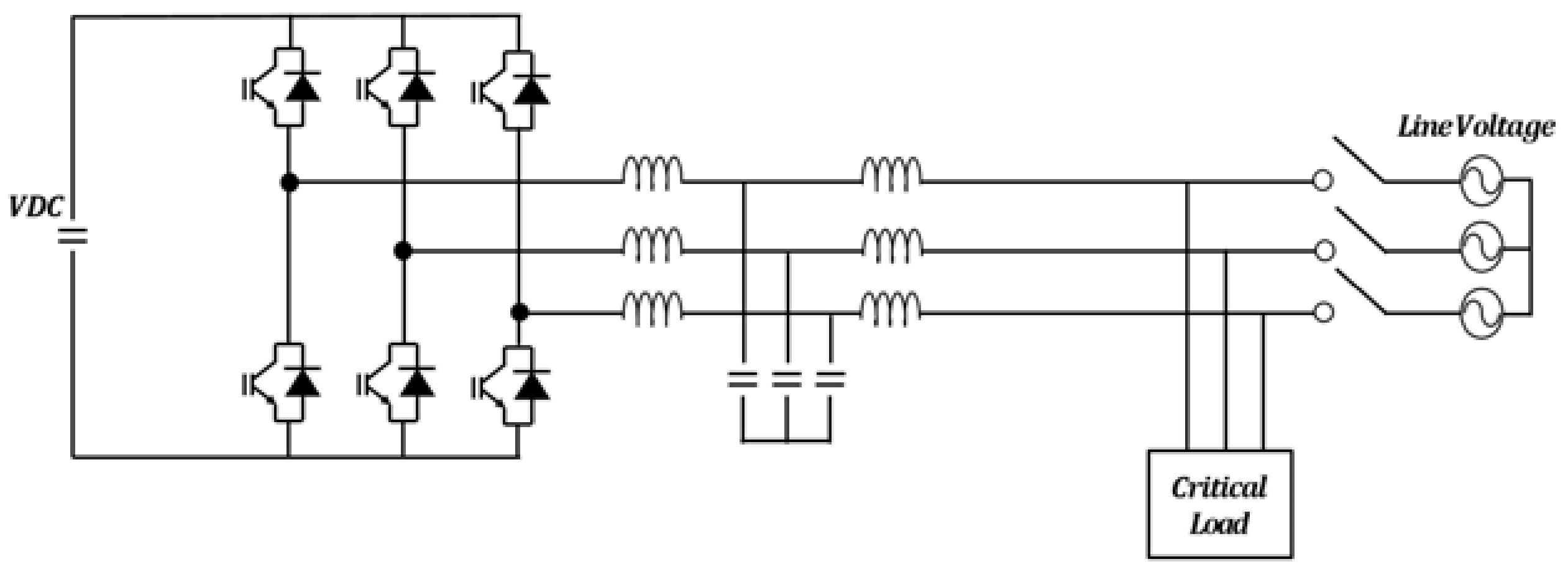
Figure 2.
(a) Three-limb core-type transformer. (b) Five-limb core-type transformer.
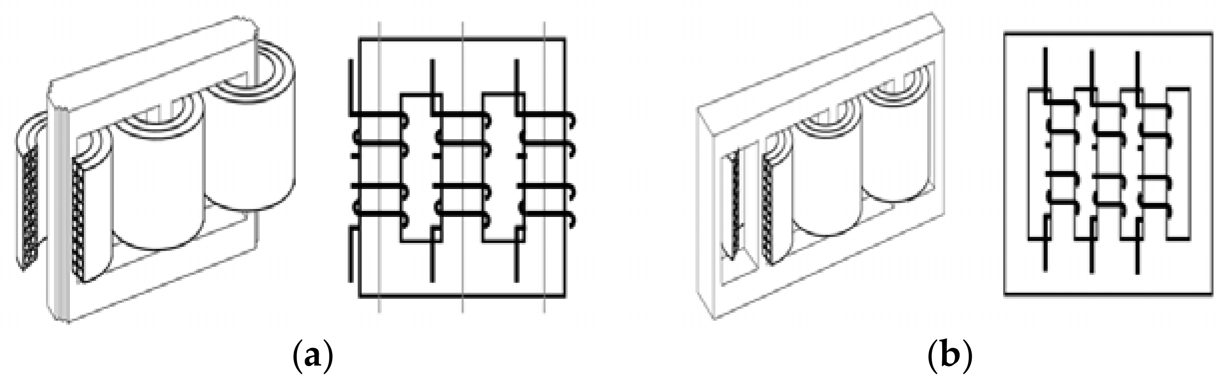
Figure 3.
Zero sequence flux of transformer core type. (a) Three-limb core-type transformer, and (b) five-limb core-type transformer.
Figure 3.
Zero sequence flux of transformer core type. (a) Three-limb core-type transformer, and (b) five-limb core-type transformer.
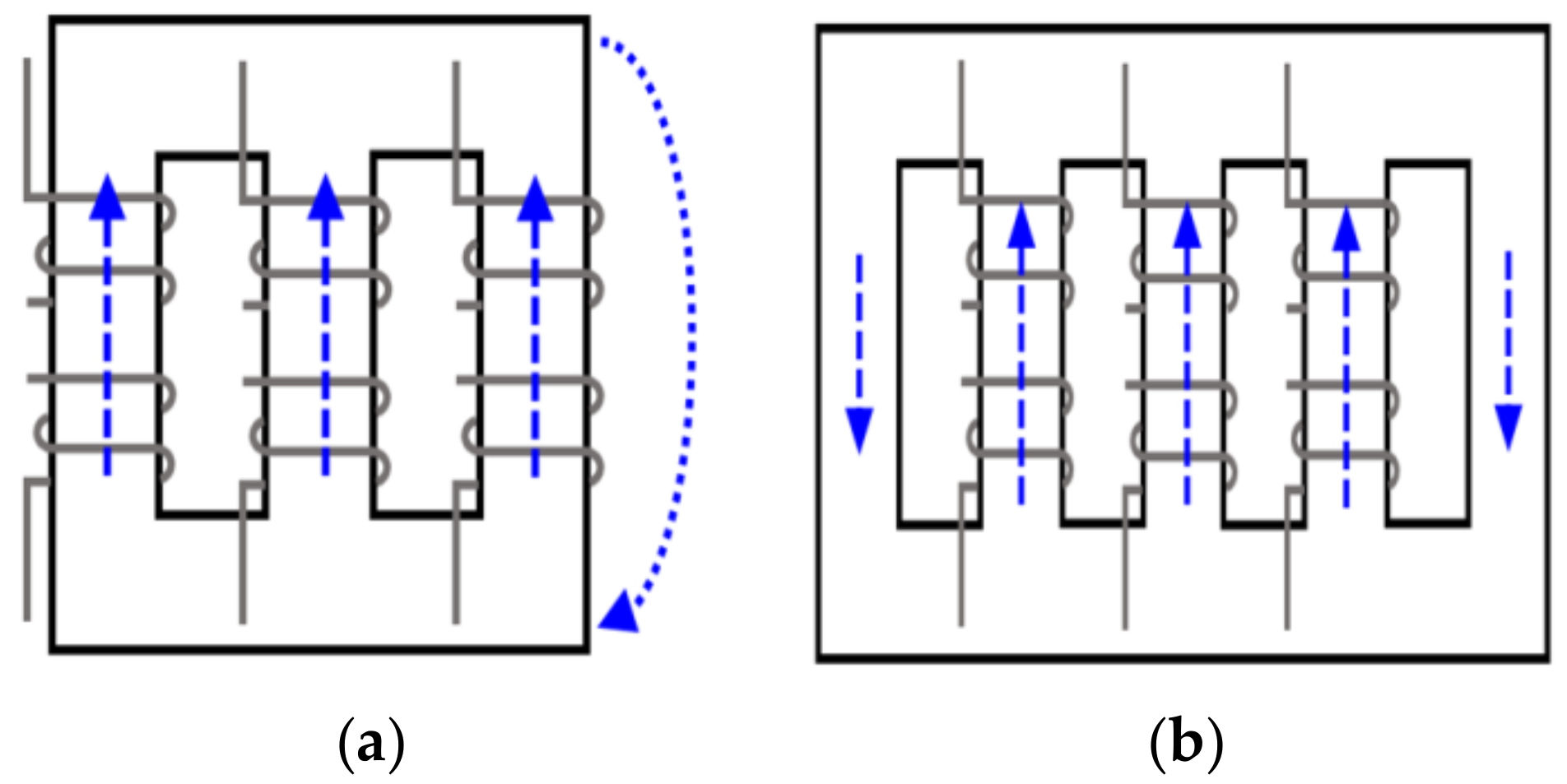
Figure 4.
Three-phase four-wire PWM(Pulse-Width-Modulation) inverter.

Figure 5.
PSIM(PowerSim)’s magnetic element. (a) Winding, (b) linear core, (c) airgap.

Figure 6.
Transformer simulation using PSIM magnetic element: (a) three-limb core-type transformer and (b) five-limb core-type transformer.
Figure 6.
Transformer simulation using PSIM magnetic element: (a) three-limb core-type transformer and (b) five-limb core-type transformer.

Figure 7.
Simulation circuit of microgrid inverter according to transformer type.
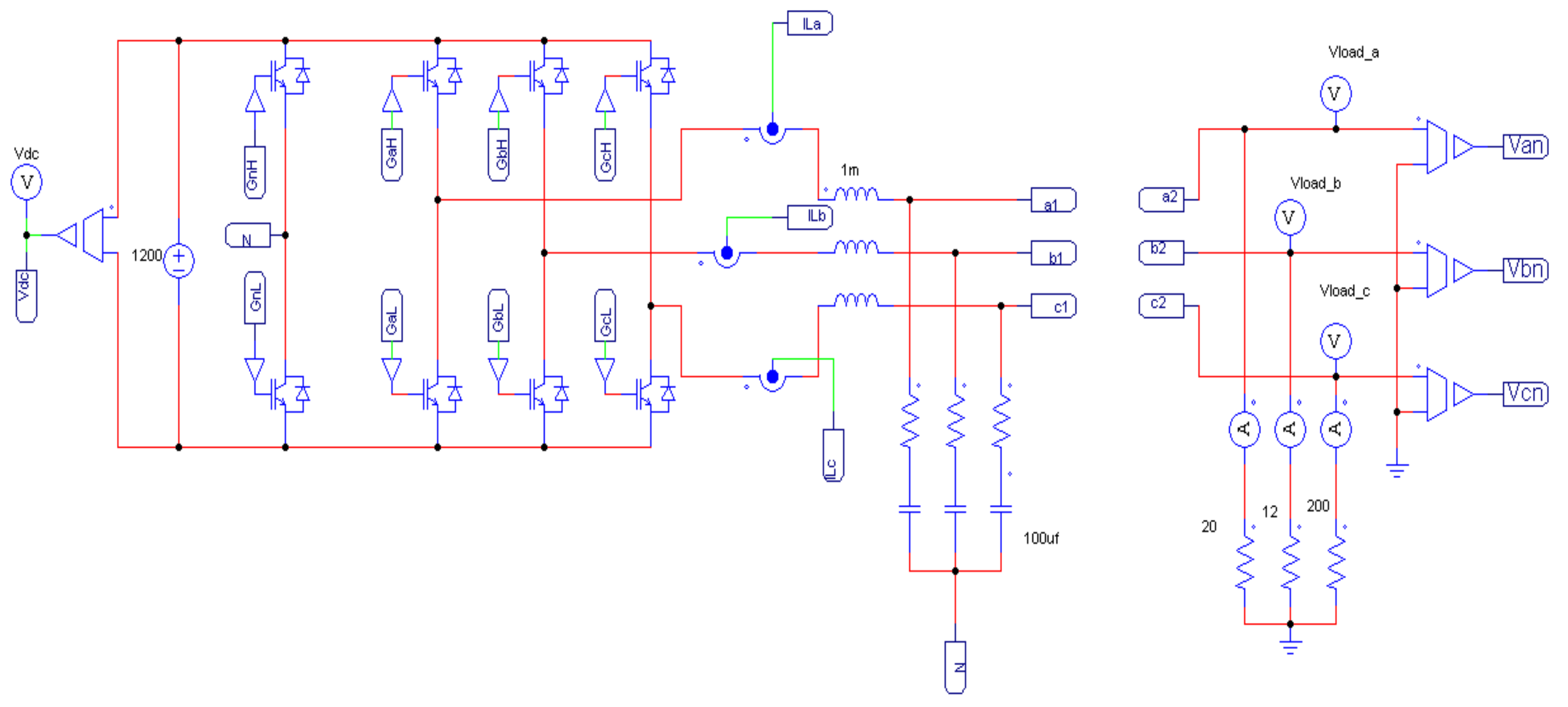
Figure 8.
Simulation results of the three-limb core-type transformer.
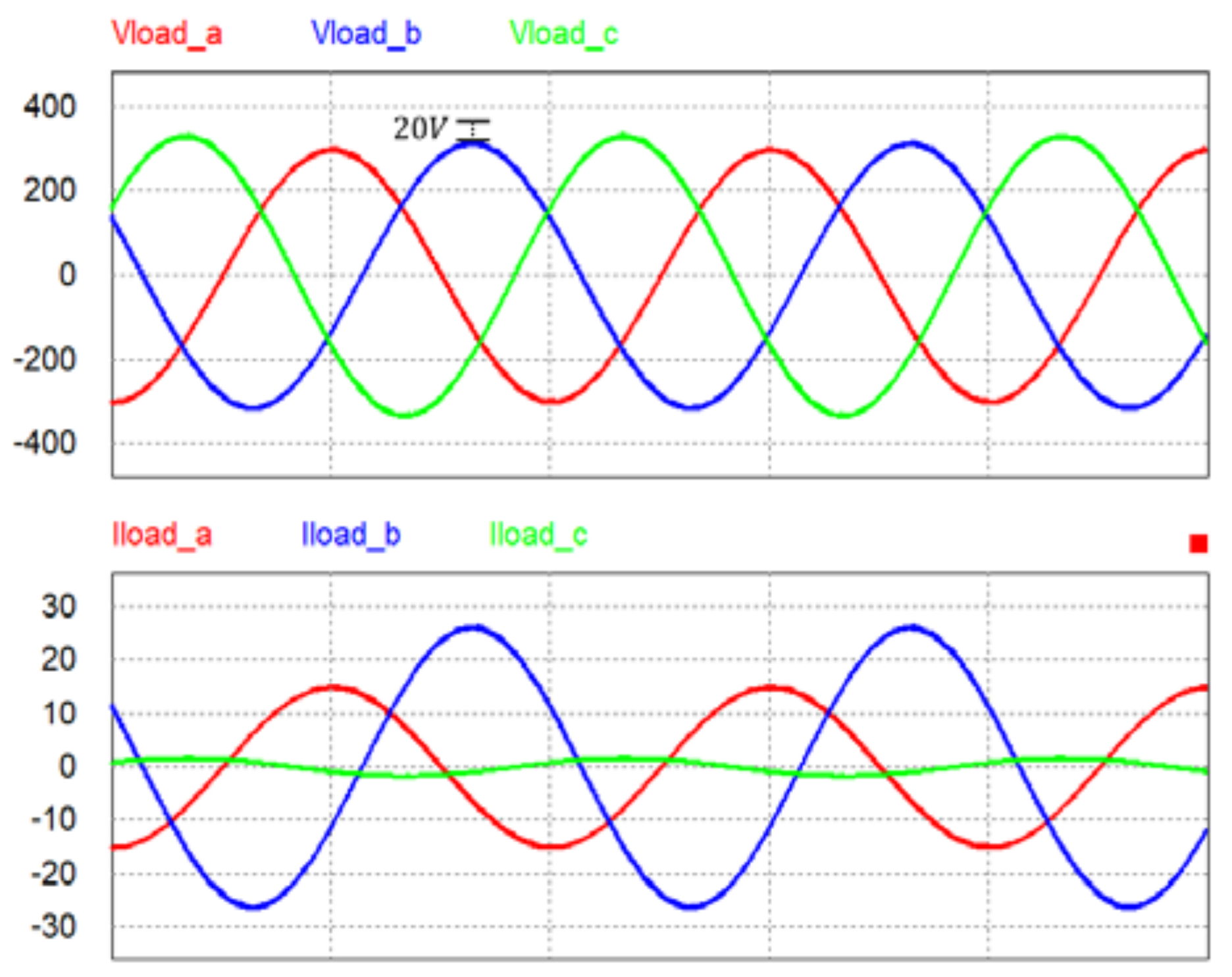
Figure 9.
Simulation results of the five-limb core-type transformer (conventional proportional-integral (PI) controller).
Figure 9.
Simulation results of the five-limb core-type transformer (conventional proportional-integral (PI) controller).

Figure 10.
Two-loop PWM inverter dq0 controller block diagram.
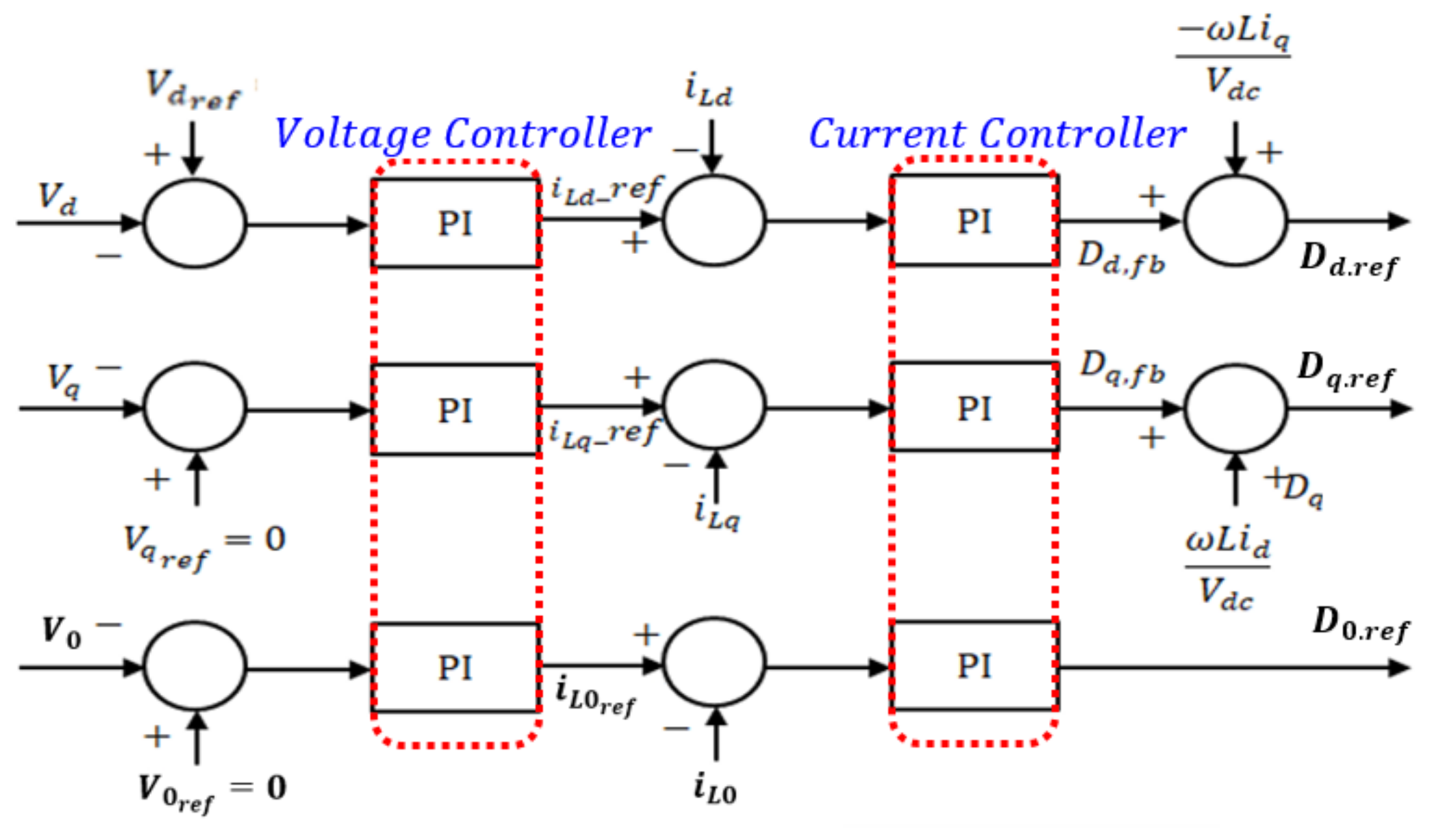
Figure 11.
PI + R controller block diagram of compensated second harmonic.
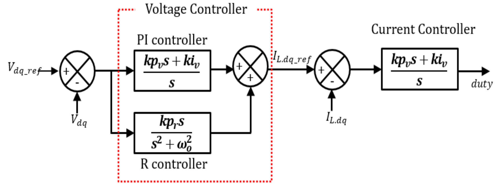
Figure 12.
Bode plot of PI + R controller.
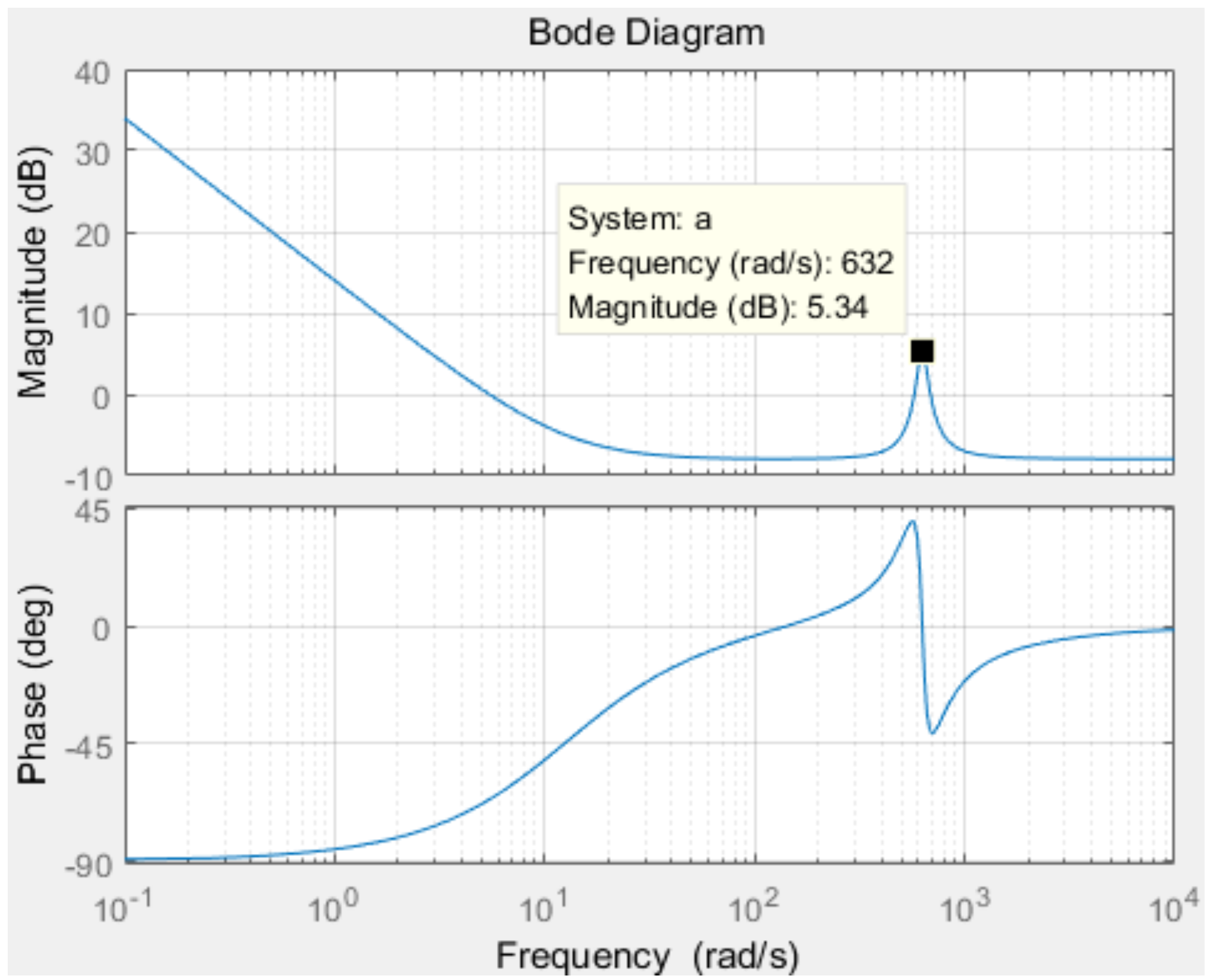
Figure 13.
Simulation results of the PI + R controller.
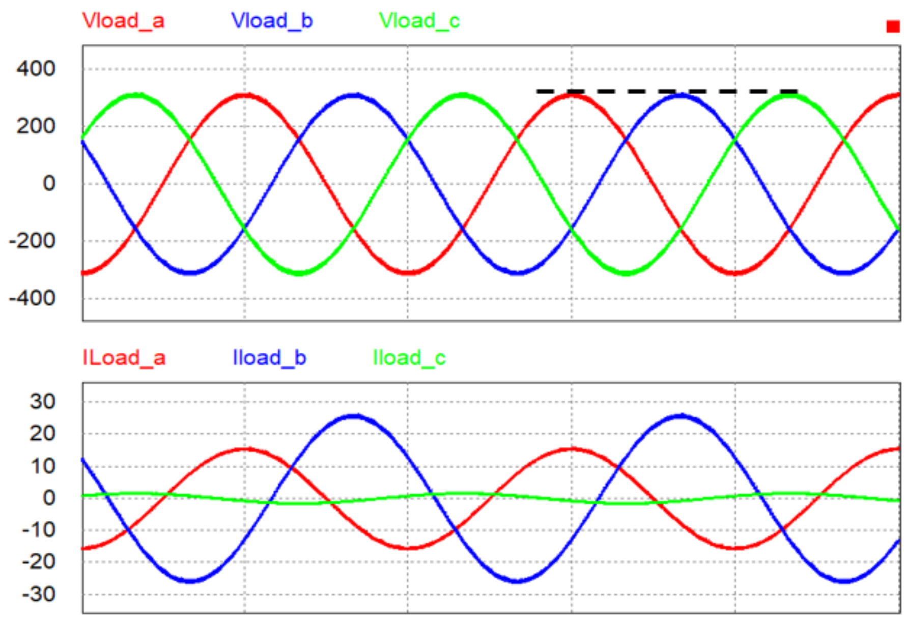
Figure 14.
Fast Fourier transform (FFT) analysis result of microgrid inverter. (a) Conventional PI controller; (b) PI + R controller.
Figure 14.
Fast Fourier transform (FFT) analysis result of microgrid inverter. (a) Conventional PI controller; (b) PI + R controller.

Figure 15.
Block diagram of the PI + MR controller-compensated nonlinear load.

Figure 16.
Bode plot of the PI + MR controller.

Figure 17.
Block diagram of the PI + MR controller compensated nonlinear/unbalanced load.

Figure 18.
Bode plot of PI + MR controller.
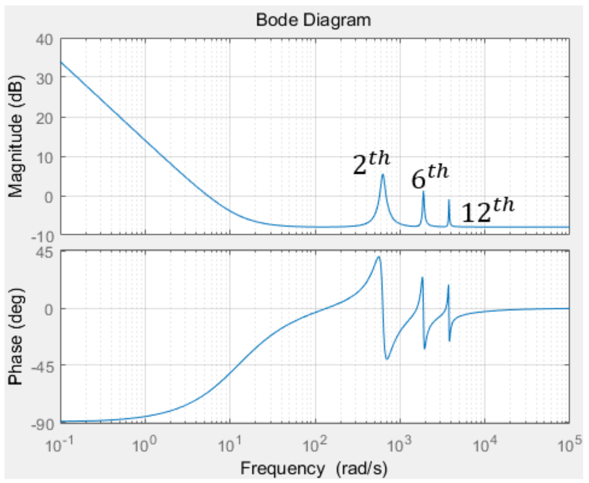
Figure 19.
Simulation results of a five-limb core-type transformer under unbalanced load conditions. (a) dq controller; (b) dq0 controller.
Figure 19.
Simulation results of a five-limb core-type transformer under unbalanced load conditions. (a) dq controller; (b) dq0 controller.

Figure 20.
Simulation results of resonant controller under an unbalanced load. (a) Conventional controller; (b) Resonant controller.
Figure 20.
Simulation results of resonant controller under an unbalanced load. (a) Conventional controller; (b) Resonant controller.
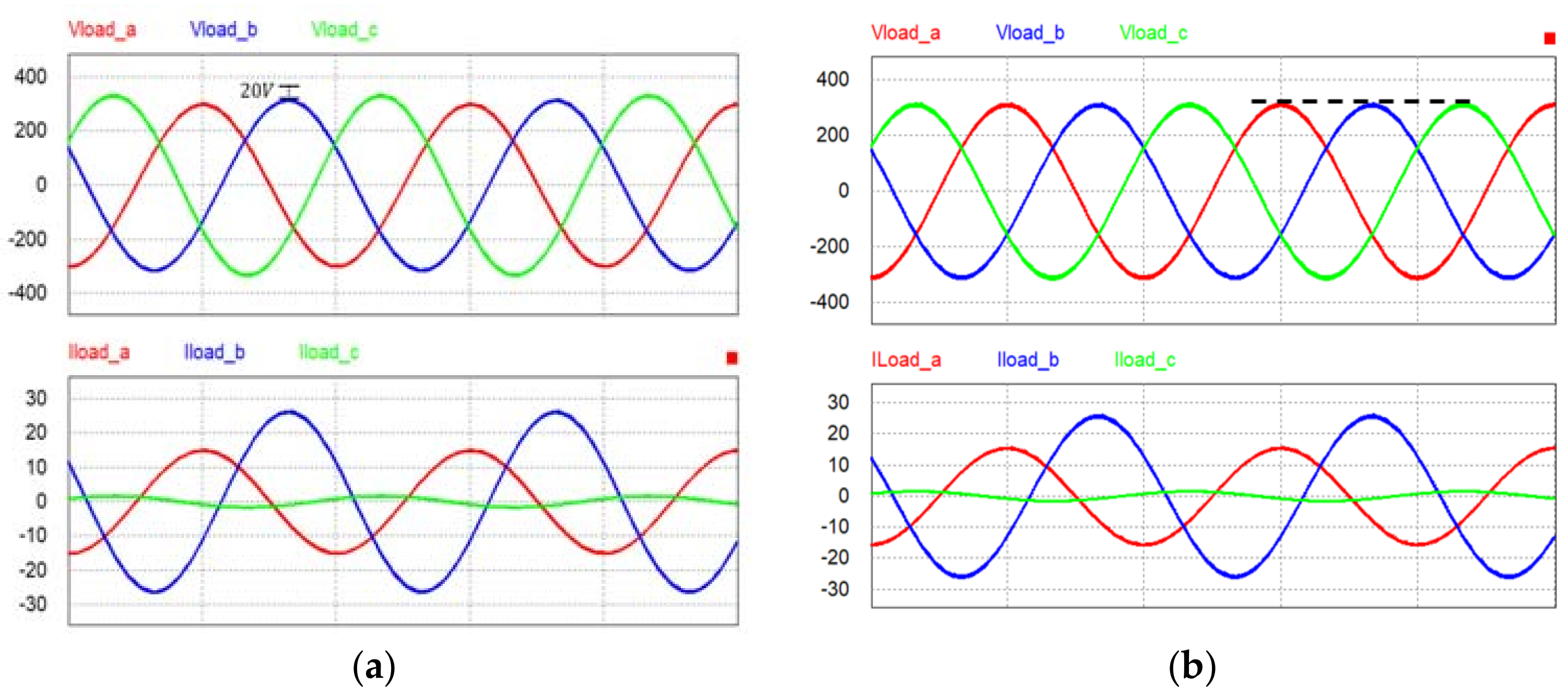
Figure 21.
FFT analysis of resonant controller under an unbalanced load. (a) Conventional controller; (b) Resonant controller.
Figure 21.
FFT analysis of resonant controller under an unbalanced load. (a) Conventional controller; (b) Resonant controller.

Figure 22.
Simulation result of resonant controller under a nonlinear load. (a) Conventional controller; (b) Resonant controller.
Figure 22.
Simulation result of resonant controller under a nonlinear load. (a) Conventional controller; (b) Resonant controller.
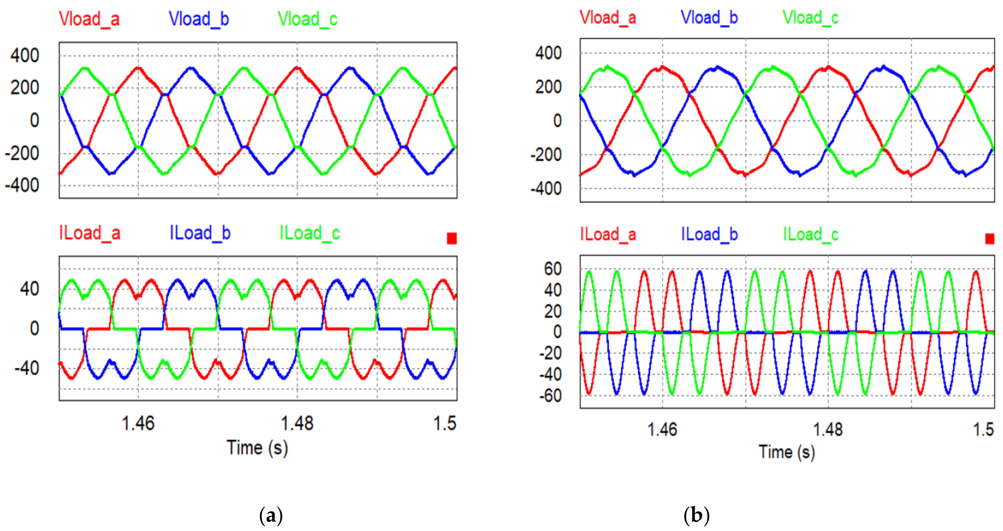
Figure 23.
FFT analysis of PI + MR control inverter under a nonlinear load. (a) Conventional controller; (b) Resonant controller.
Figure 23.
FFT analysis of PI + MR control inverter under a nonlinear load. (a) Conventional controller; (b) Resonant controller.

Table 1.
System parameters.
| Parameter | Value |
|---|---|
| Rated power | 200 kW |
| Output voltage | 380 V |
| Line frequency | 50 Hz |
| Inverter | Three-phase, four-wire |
| Transformer core type | Five-lime core transformer |
| Balance load | 20 Ω |
| Unbalanced load | 20 Ω, 12 Ω, 200 Ω |
| Nonlinear load | Three-phase diode rectifier |
| Filter inductor | 2 mH |
| Output capacitor | 100 μF |
| Voltage controller bandwidth | 15 Hz |
| Current controller bandwidth | 1 kHz |
| Resonant controller gain (2th, 6th, 12th) | 10, 6, 4 |
Table 2.
THD (Total Harmonic Distortion) of controller.
| THD | Conventional Controller | Resonant Controller |
|---|---|---|
| Voltage | 0.08 | 0.05 |
© 2018 by the authors. Licensee MDPI, Basel, Switzerland. This article is an open access article distributed under the terms and conditions of the Creative Commons Attribution (CC BY) license (http://creativecommons.org/licenses/by/4.0/).
Share and Cite
MDPI and ACS Style
Lim, J.-U.; Kim, H.-W.; Cho, K.-Y.; Bae, J.-H. Stand-Alone Microgrid Inverter Controller Design for Nonlinear, Unbalanced Load with Output Transformer. Electronics 2018, 7, 55. https://doi.org/10.3390/electronics7040055
AMA Style
Lim J-U, Kim H-W, Cho K-Y, Bae J-H. Stand-Alone Microgrid Inverter Controller Design for Nonlinear, Unbalanced Load with Output Transformer. Electronics. 2018; 7(4):55. https://doi.org/10.3390/electronics7040055
Chicago/Turabian StyleLim, Jae-Uk, Hag-Won Kim, Kwan-Yuhl Cho, and Joung-Hwan Bae. 2018. "Stand-Alone Microgrid Inverter Controller Design for Nonlinear, Unbalanced Load with Output Transformer" Electronics 7, no. 4: 55. https://doi.org/10.3390/electronics7040055
Note that from the first issue of 2016, this journal uses article numbers instead of page numbers. See further details here.