Article

Harmonic Extended State Observer Based Anti-Swing Attitude Control for Quadrotor with Slung Load

1
School of Instrumentation Science and Optoelectronics Engineering, Beihang University, Beijing 100191, China
2
School of Mechanical Engineering and Automation, Beihang University, Beijing 100191, China
3
State Key Laboratory of Virtual Reality Technology and System, Beijing 100191, China
*
Author to whom correspondence should be addressed.
Electronics 2018, 7(6), 83; https://doi.org/10.3390/electronics7060083
Submission received: 8 May 2018 / Revised: 27 May 2018 / Accepted: 28 May 2018 / Published: 29 May 2018
(This article belongs to the Special Issue Autonomous Control of Unmanned Aerial Vehicles)

Abstract

:
During the flight of the quadrotor, the existence of a slung load will exert a swing effect on the system and the motion of which will significantly change the dynamics of the quadrotor. The external torque caused by the slung load can be considered as a kind of disturbance and it is a threat to the attitude control stability of the system. In order to solve this problem, a high precision disturbance compensation method is presented in this paper, based on the harmonic extended state observer (HESO). Firstly, a generic mathematical model for the quadrotor-slung load system is obtained via the Lagrangian mechanics, and according to the analysis of the slung load motion, we obtain the disturbance as a form of periodic equation. Secondly, based on the dynamic model of the disturbance, we propose a HESO to achieve high precision disturbance estimation and its stability is proved by Lyapunov theory. Thirdly, we designed an attitude tracking controller based on backstepping method, and discussed the stability of the entire system. Finally, numerical simulations and real time experiments are carried out to evaluate the performance of the proposed method. Our results show that the robustness of the quadrotor subject to slung load has been improved.

1. Introduction

In recent years, the research on quadrotor vehicles has attracted great interest due to the wide range of civil and military applications, and many achievements have been made [1,2]. As a new kind of unmanned aerial vehicle (UAV), the quadrotor is a small rotorcraft with four propellers driven by four direct current (DC) motors respectively [3]. Compared with traditional helicopters, the structure of the quadrotor is simpler and more efficient, and has significant advantages in precise hovering, aggressive maneuver, vertical take-off and landing (VTOL) [4,5], etc.
Like traditional helicopters, quadrotor vehicles have many important applications in carrying slung load, such as deploying supplies in military operations, or delivering first-aid kits for personal assistance to the victims in disasters like floods, earthquakes, fires, industrial accidents, etc. [6,7], and the research work addressing quadrotor vehicles with slung load becomes an attractive topic. On this application, the major difficulty in modeling and control study is the coupled effects between the quadrotor vehicles and the slung load [8]. The external slung load behaves like a pendulum and the motion of which will significantly change the dynamics of the quadrotor. Moreover, the quadrotor vehicle is a typical underactuated, strong coupled, nonlinear system [9], and inherently unstable without close-loop controller [10]. If the pendulous motion of the load exceeds certain limits, the stability of control system will be broken because of the changes in dynamic characteristics of the plant. Therefore, improving the robustness of the controller subject to the oscillation of slung load is very necessary.
In the relevant literatures on the quadrotor, the problem of addressing quadrotor-slung load system has been discussed in some publications. The mathematical model of the entire system is derived by the Newton-Euler formulation in [8,11], however, there is no further analysis on the dynamic characteristics of the slung load motion in detail. In [12], the slung load is modeled as a point mass spherical pendulum, and a related adaptive control method is proposed to handle the additional forces and torques acting on the quadrotor. In [13], a generalized approach is presented using an iterative optimal control algorithm, and a series of complex tasks are thus solved without the need for manual manipulation of the system dynamics, heuristic simplifications, or manual trajectory generation. In [14], a nonlinear dynamic model is presented, and an interconnection and damping assignment-passivity based Control (IDA-PBC) methodology is used for precise payload’s positioning with stabilization of the swing angles to the minimum of the desired energy function.
Alternatively, the effect of slung load on the quadrotor can be considered as a kind of disturbance [15]. Therefore, in order to improve system reliability and achieve the requirements of high precision control, the disturbance and uncertainty estimation and attenuation (DUEA) method would be a potential solution. In recent years, this method has been widely used and achieved good results [16,17] The framework of DUEA can be divided into two parts, namely, a disturbance and uncertainty estimator (DUE) and a feedback controller (FC). In the first part, DUE is designed to estimate the disturbances so that they could be compensated in the feedforward loop. Then the FC in the second part is designed to guarantee fast convergence of the closed-loop system. In this framework the DUE plays an important role because the performance of the closed-loop system is largely determined by the estimation accuracy of it. Therefore, a series of observers have been proposed as the DUE so far to improve estimation accuracy under different conditions, such as disturbance observer (DO) [18,19], extended state observer (ESO) [15,20,21] and proportional integral observer (PIO) [22,23] etc. By the appropriate use of the observer, disturbance rejection performance and robustness of the existing control system could be significantly improved.
The extended state observer (ESO), known as the key module of active disturbance rejection control, can estimate both the states of system and the total disturbances with less dependence on model information [24,25]. This method was first proposed by Han in 1990s and the basic idea behind ESO is to view disturbance as an extended state and utilize observer to estimate it [24]. Traditionally, ESO approaches focus primarily on dealing with slowly changing disturbances. However, it’s obvious that the disturbance caused by the slung load is periodic, which cannot be estimated by traditional ESO thoroughly [26]. Therefore, an enhancement of ESO that can handle periodic disturbance is necessary in this field. In [27], a higher-order ESO is investigated, from the results, it can be seen that the higher-order ESO can improve the estimation accuracy of sinusoidal external disturbances more or less, while, there still exists a periodic estimation error that will in turn decrease the control accuracy of the closed-loop system. Furthermore, the higher level of the observer order will lead to a higher observer gain, which will in return excite the sensor noise and introduce them into the control loop. The internal model principle is applied for generalized ESO in [28] and harmonic disturbance observer (HDO) in [29] by embedding the disturbance dynamics into the observer, and the disturbance estimation performance is improved.
Motivated by these methods, a harmonic extended state observer based anti-swing attitude control method is proposed for a quadrotor subject to slung load in this article, where the periodic disturbance caused by slung load motion is compensated by the estimated state signals produced of the HESO. The main contributions of this paper are summarized as follows: (1) Build the generic mathematical model for the quadrotor-slung load system by the Lagrangian mechanics, and analyze the characteristics of the slung load motion in detail. (2) Propose a HESO based on the characteristics of the slung load motion.
The outline of this paper is as follows: The mathematical model and the control problems of quadrotor-slung load system are formulated in Section 2. A HESO is designed in Section 3. In Section 4, an attitude tracking controller is designed via backstepping method. Numerical simulation and real time experimental results are presented in Section 5, and the conclusions are summarized in Section 6.

2. Mathematical Model and Problem Formulation

2.1. Preliminaries

2.1.1. Notations and Assumptions

Throughout this paper, the following notations will be used. is the set of real numbers. Let · denote the 2-norm of a vector or a matrix. For a given vector v = [ v 1 , , v n ] T n , | | v | | = v T v , and for a given matrix A n × n , | | A | | = λ max ( A T A ) , where λ max ( · ) is the maximal eigenvalue of the matrix. In addition, the operator S ( · ) maps a vector x = [ x 1 x 2 x 3 ] T to a skew symmetric matrix as:
S ( x ) = [ 0 x 3 x 2 x 3 0 x 1 x 2 x 1 0 ]
In this section, the mathematical model of the quadrotor-slung load system is established. As shown in Figure 1, we consider this system consists of three parts: a quadrotor, a cable and a payload. And before our work, the following assumptions are made:
(1)
The slung load is considered as a particle and only swings in a plane. The length of the connecting cable is constant and known.
(2)
The inelastic cable is massless and always tight and no consideration of the energy loss caused by the friction force in the swing.
(3)
The aerodynamic effects on the load are neglected.

2.1.2. Quaternion Operations

In order to avoid the singularity problem of trigonometric functions, unit quaternion q = [ q 0 q v T ] T 4 , q = 1 is used to represent rotation [30]. Following are the operations we used.
The quaternion multiplication is:
q 1 q 2 = [ q 01 q 02 q v 1 T q v 2 q 01 q v 2 + q 02 q v 1 S ( q v 2 ) q v 1 ]
The relationship between rotation matrix R A B and q is calculated as:
R A B = ( q 0 2 q v T q v ) I 3 + 2 q v q v T + 2 q 0 S ( q v )
R ˙ A B = S ( ω ) R A B
The derivative of a quaternion is given by the quaternion multiplication of the quaternion q and the angular velocity of the plant ω :
q ˙ = [ q ˙ 0 q ˙ v ] = 1 2 q [ 0 ω ] = 1 2 [ q v T S ( q v ) + q 0 I 3 ] ω
The quaternion error q e is given as the quaternion multiplication of the conjugate of the desired quaternion q d and the actual quaternion q :
q e = q d q = [ q 0 e q v e ] = [ q 0 q 0 d + q v T q v d q 0 d q v q 0 q v d + S ( q v ) q v d ]
where q = [ q 0 q v ] T is the conjugate of the quaternion q .

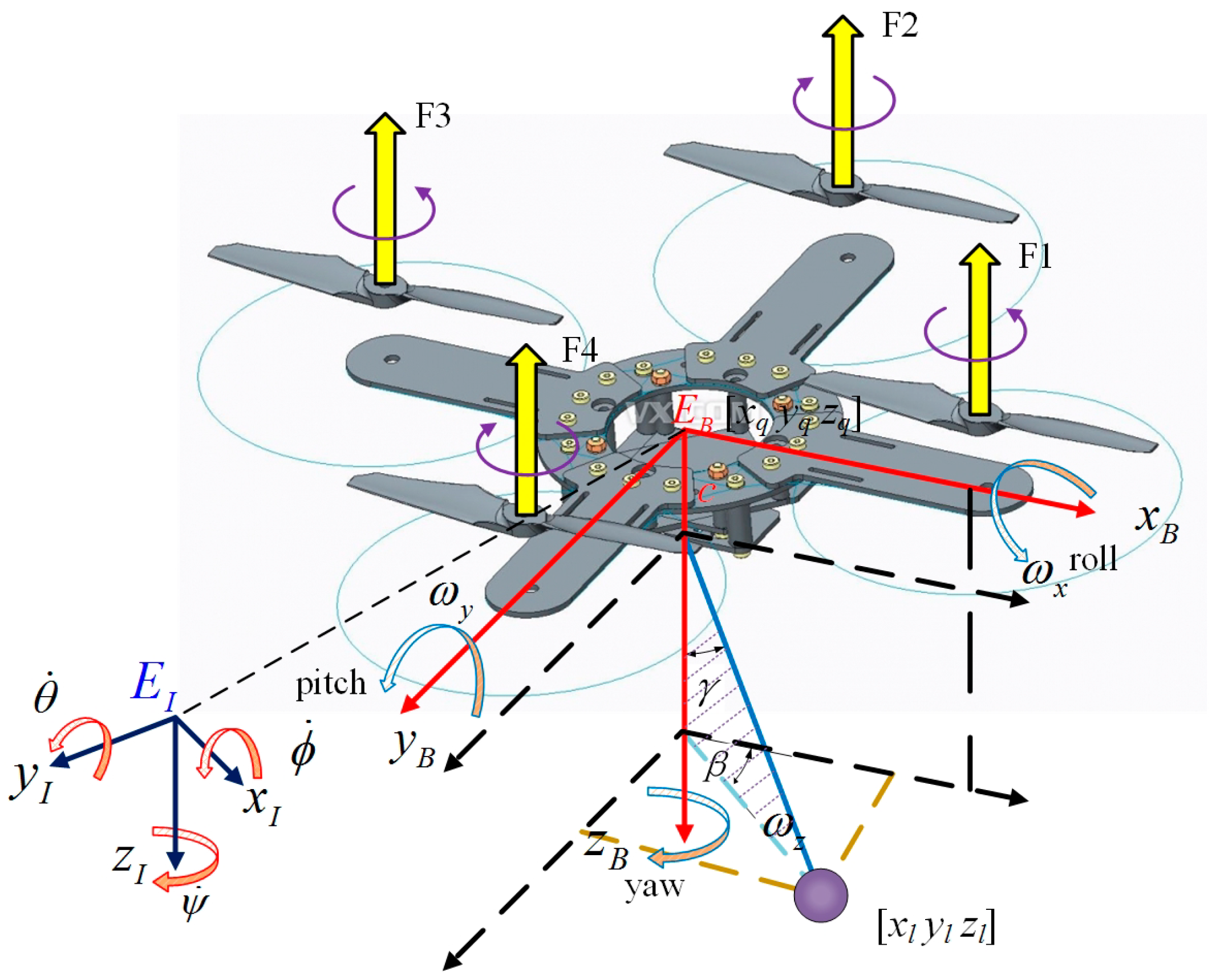
2.2. Mathmetical Model of Quadrotor-Slung Load system

Firstly, the quadrotor can be considered as a rigid cross frame attached with four rotors, and the center of gravity coincides with the body-fixed frame origin. The simplified model of the quadrotor is presented in Figure 1, rotors R1 and R3 rotate counterclockwise, and rotors R2 and R4 rotate clockwise, each propeller rotates at the angular speed Ω i and produces a force Fi (i = 1,2,3,4) along the negative z-direction relative to the body frame [30,31]:
F i = k T Ω i 2
where k T > 0 denotes the aerodynamic coefficient which consists formed of the atmospheric density ρ , the radius of the propeller r , and the thrust coefficient c T . In addition, due to the spinning of the rotors, a reaction torque Mi (i = 1,2,3,4) is generated on the quadrotor body by each rotor:
M i = ( 1 ) i + 1 k D Ω i 2
where k D > 0 denotes the drag coefficient of the rotor, which depends on the same factors as k T .
The variation of the orientation is achieved by varying the angular speed of a specific rotor. The total force and torque acting on the quadrotor are defined as follows:
u = [ τ ϕ τ θ τ ψ ] = [ 0 l k T 0 l k T l k T 0 l k T 0 k D k D k D k D ] [ Ω 1 2 Ω 2 2 Ω 3 2 Ω 4 2 ]
where u represents the attitude control signal to be designed.
In the mathematical model of quadrotor, three coordinate frames are considered: the non-moving inertial coordinate frame E I : { o I , x I , y I , z I } , the body-fixed coordinate frame E B : { o B , x B , y B , z B } and the desired frame E D : { o D , x D , y D , z D } to represent the actual attitude and desired attitude of quadrotor respectively. Note that NED coordinates are used to define all frames. In the inertial frame E I , the position of the quadrotor is X q = [ x q y q z q ] T 3 , the attitude angle is Θ = [ ϕ θ ψ ] T 3 and the quaternion expression of the attitude is q = [ q 0 q v ] T 4 . In the body-fixed frame E B , the angular velocity of is ω = [ ω x ω y ω z ] T 3 . Thus, the rotation matrix from E B to E I can be represented as:
R B I = [ cos θ cos ψ sin ϕ sin θ cos ψ cos ϕ sin ψ cos ϕ sin θ cos ψ + sin ϕ sin ψ cos θ sin ψ sin ϕ sin θ sin ψ + cos ϕ cos ψ cos ϕ sin θ sin ψ sin ϕ cos ψ sin θ sin ϕ cos θ cos θ cos ψ ]
and the rotation velocity transfer matrix can be given as:
P = [ 1 sin ϕ tan θ cos ϕ tan θ 0 cos ϕ sin ϕ 0 sin ϕ cos 1 θ cos ϕ cos 1 θ ]
Thus, the rotational kinematic equations with respect to the inertial frame E I can be expressed as:
Θ ˙ = P ω
Secondly, we study the slung load. The position of the hook point is defined as c = [ 0 0 c ] T in body frame E B . According to previous assumptions, the relationship between the position of the slung load X l = [ x l y l z l ] T 3 and X q are:
X l = X q + R B I c + L c [ sin γ cos β sin γ sin β cos γ ]
where γ ( 90 , 90 ) is the pendulum angle between the cable and the positive orientation of o I z I , β is the angle between the pendulum plane and the x I o I z I plane, and L c is the length of the cable. Moreover, according to the former assumptions, β and L c are constant.
Finally, we use Lagrangian mechanics to summarize the dynamics of the quadrotor-slung load system. Compared with the Newtonian mechanics, this choice eliminates the need for the constraint forces to enter into the resultant system of equations, so that fewer equations are needed. As shown in Figure 1, the entire system has seven degrees of freedom (DOF): pendulum angle of the slung load γ , position of the quadrotor X q = [ x q y q z q ] T and attitude of the quadrotor Θ = [ ϕ θ ψ ] T . Therefore, we defined the generalized coordinate of the quadrotor-slung load system as η = [ x q y q z q ¦   ϕ θ ψ ¦   γ ] T . The expressions for the kinetic and potential energies will be presented in order to obtain the Lagrangian of the system. The total kinetic energy function of the quadrotor-slung load system, resulting from the translational and rotational motions can be portioned as the sum of the translational kinetic energy:
T t = 1 2 m q X ˙ q 2 + 1 2 m l X ˙ l 2
And the rotational kinetic energy of the entire system:
T r = 1 2 ω T J ω = 1 2 Θ ˙ T P T J P 1 Θ ˙
where the inertia matrix J = diag ( J x , J y , J z ) is diagonal.
And the total potential energy function of the system results from the sum of the potential energies of the quadrotor and the slung load:
V = ( m q z q + m l z l ) g
Thus, the Lagrangian of the generalized system can be defined as:
L ( η , η ˙ ) = T t + T r V
Notice that gravity G is the conservative force in this system, while total lift F = R B I [ 0 0 F i ] T and torque u are non-conservative forces, the Euler Lagrangian equations of the second kind can be obtained as:
d d t ( L ( η , η ˙ ) η ˙ ) L ( η , η ˙ ) η = Q
where Q = [ F x F y F z ¦   τ ϕ τ θ τ ψ ¦   0 ] T 7 is the non-conservative generalized force.
When the quadrotor is carrying a slung load, Large-scale maneuvers should be avoided, therefore, the coupling of angular velocity between different channels can be ignored. Then, we assume P I 3 when calculating the dynamic quadrotor-slung load system. According to Equations (14)–(18), the dynamic model can be expressed as:
T : { x ¨ q = 1 m q + m l ( F x m l L c ( γ ¨ cos γ γ ˙ 2 sin γ ) cos β m l c θ ¨ ) y ¨ q = 1 m q + m l ( F y m l L c ( γ ¨ cos γ γ ˙ 2 sin γ ) sin β + m l c ϕ ¨ ) z ¨ q = 1 m q + m l ( F z + m l L c ( γ ¨ sin γ + γ ˙ 2 cos γ ) ) + g
R : { ϕ ¨ = 1 J x + m l c 2 ( τ ϕ + m l c ( y ¨ q + L c ( γ ¨ cos γ γ ˙ 2 sin γ ) sin β ) ) θ ¨ = 1 J y + m l c 2 ( τ θ m l c ( x ¨ q + L c ( γ ¨ cos γ γ ˙ 2 sin γ ) cos β ) ) ψ ¨ = 1 J z τ ψ
γ ¨ = 1 L c ( ( x ¨ q cos β + y ¨ q sin β ) cos γ + ( z ¨ Q + g ) sin γ ) + c L c Δ ( ϕ , θ , γ )
where Δ ( ϕ , θ , γ ) represents the residual term of γ ¨ .
According to [30], we can obtain the attitude kinematic of the quadrotor as:
q ˙ = 1 2 q [ 0 ω ] T

2.3. Analysis of Slung Load Motion

In this article, we consider the effect of slung load on the quadrotor as a kind of disturbance. In order to realize high precision estimation of the disturbance, the characteristics of the disturbance need to be analyzed.
The derived equations of motion of the load and quadrotor are highly nonlinear and strongly coupled, thus, they are difficult to be used for motion analysis. Therefore, we trimmed the mathematical near hovering or uniform linear flight. In this condition, we have X ¨ q 0 . And in actual flight c L c , then we have c L c 1 0 . From Equation (20), we can see that the load movement can hardly affect ψ , therefore, disturbance in pitch and roll channels are considered in this condition. The trimmed results of the rotational dynamic are:
{ ϕ ¨ = 1 J y + m l c 2 ( τ ϕ + d ϕ ) θ ¨ = 1 J y + m l c 2 ( τ θ + d θ ) γ ¨ = 1 L c g sin γ
where d ϕ = m l c L c ( γ ¨ cos γ γ ˙ 2 sin γ ) sin β and d θ = m l c L c ( γ ¨ cos γ γ ˙ 2 sin γ ) cos β are the torque disturbance caused by the slung load in roll and pitch channel respectively.
Then, analyze the motion of slung load. When γ is a small angle, we have sin γ γ and cos γ 1 . Thus, we can rewrite Equation (23) as:
γ ¨ = 1 L c g γ
According to Equation (24), we can calculate that:
γ = A 0 sin ( g L c 1 t + χ 0 )
where A 0 and χ 0 are the unknown amplitude and phase related to initial conditions.
Substituting Equation (25) into Equation (23), we have:
d = [ d ϕ d θ d ψ ] = [ A 1 , ϕ sin ( g L c 1 t + χ 1 , ϕ ) + A 2 , ϕ sin ( 3 g L c 1 t + χ 2 , ϕ ) + Δ ϕ A 1 , θ sin ( g L c 1 t + χ 1 , θ ) + A 2 , θ sin ( 3 g L c 1 t + χ 2 , θ ) + Δ ϕ 0 ]
where Δ i ( i = ϕ , θ ) are the unmodeled residual of the disturbance in each channel.
According to the above analysis, the disturbance torque caused by the slung load is a sum-of-sinusoids function which has two frequencies ϖ 1 = g L c 1 , ϖ 2 = 3 g L c 1 , while the amplitude A 1 , i , A 2 , i and phase χ 1 , i , χ 2 , i ( i = ϕ , θ ) are unknown.

2.4. Problem Formulation

In order to study the transient and steady-state characteristics of the quadrotor, the dynamics of attitude error are introduced. We use ω d = [ ω d , x ω d , y ω d , z ] T and q d = [ q 0 d q v d ] T to denote the desired angular velocities and attitude respectively, thus:
ω e = ω R D B ω d
where ω e = [ ω e , x ω e , y ω e , z ] T is the tracking error vector of the angular velocities. Then, we can obtain the dynamics of ω e according to Equations (4), (20) and (27):
ω ˙ e = S ( ω d ) R D B ω d R D B ω ˙ d + J 0 1 u + J 0 1 d
where J 0 = diag ( J x + m l c 2 , J y + m l c 2 , J z ) , R D B can be calculated according to Equations (3) and (6). And according to Equations (5), (6) and (27), we can obtain the kinematics of attitude tracking error
q ˙ e = 1 2 q e [ 0 ω e ] T = 1 2 [ q v e T S ( q v e ) + q 0 e I 3 ] ω e
The problem we try to tackle in this work is to design a continuous control law u using only the measurable system output ω and q such that the error of attitude ω e and q e converge to zero in presence of the slung load. In order to ensure the robustness of the controller, the DUEA strategy is necessary
Figure 2 illustrates the control scheme that we designed. Based on the DUEA control methodology, the attitude control problem for quadrotor can be divided into two components: design the feedforward loop so that the periodic disturbance is estimated by HESO and compensated this way; and design the feedback loop that regulates the orientation to track the desired attitude produced by the commander timely. Therefore, the control signal u contains two parts as:
u = u N + u E
where u N is the nominal control input vector and u E is the disturbances attenuation input vector.

3. Design and Stability Analysis of HESO

In this section, the design of HESO, which provides the disturbance estimate for the controller, is described in detail. As for the DUEA control methodology, the control performance of closed loop system will be largely determined by the observation performance. However, the disturbances acting on quadrotor are periodic, which cannot be accurately estimated by traditional ESO thoroughly [28]. Therefore, in order to enhance the performance of feedback controller, a HESO is designed to estimate the periodic disturbances, and the stability analysis is carried out afterwards.

3.1. Design of HESO

According to the analysis of the disturbances in previous section, we can conclude that the external disturbances caused by the slung load have the same characteristic in roll and pitch channel. Without loss of generality, the design process in i ( i = ϕ , θ ) channel is demonstrated in detail. Firstly, we can rewrite the time varying disturbance as:
d i = A 1 , i sin ( ϖ 1 t + χ 1 , i ) d 1 , i + A 2 , i sin ( ϖ 2 t + χ 2 , i ) d 2 , i + Δ i
where Δ ˙ i = δ i is upper bounded δ i σ i . In order to establish the model of equivalent disturbance, we write Equation (31) as a form of state equation
{ ζ ˙ i = A d ζ i + δ d , i d i = C d ζ i
where
A d = [ 0 1 ϖ 1 2 0 0 1 ϖ 2 2 0 0 1 0 0 ] , δ d , θ = [ 0 0 0 0 0 δ θ ] , C d = [ 1 0 1 0 1 0 ] T
ζ i = [ d 1 , i d ˙ 1 , i d 2 , i d ˙ 2 , i d 3 , i d ˙ 3 , i ] T is the system state and δ d , i is the perturbation term of the disturbance.
Then, consider the SISO nonlinear Equation (23), we have
( J i + m l c 2 ) ω ˙ i = τ i + d i
Define x i = [ ( J i + m l c 2 ) ω i ζ i T ] T as the new state vector, the reconstructed system can be written as:
{ x ˙ i = [ 0 C d 0 6 × 1 A d ] A x i + [ 1 0 6 × 1 ] B τ i + [ 0 δ d , i ] δ i y i = [ 1 0 1 × 6 ] C x i
Note that in the reconstructed model of quadrotor, it can be verified that the pair ( A , C ) is observable [28].
From the reconstructed system model in Equation (34), the observer is designed as follows:
{ x ^ ˙ i = A x ^ i + B τ i + L e , i ( y i y ^ i ) y ^ i = C x ^ i
where x ^ i = [ ( J i + m l c 2 ) ω ^ i ζ ^ i T ] T is the stats of the observer, y ^ i is the estimate of the output y i , and L e , i = [ l 0 l 1 l 2 l 3 l 4 l 5 l 6 ] T is the observer gain to be designed.
By defining the estimation error of the observer as x ˜ i = x i x ^ i , we have the following equation:
x ˜ ˙ i = ( A L e , i C ) A ¯ x ˜ i + [ 0 δ d , i ] δ i
From Equation (36), we can find that the estimation accuracy is partly determined by the perturbation term δ i , thus in order to increase the estimation accuracy of the observer, δ i should be decreased. Compared with the traditional higher order ESO, the equivalent disturbance model is introduced in HESO which makes the model more precise and the perturbation δ d , i smaller [28].

3.2. Convergency Analysis of HESO

Frist, define the Lyapunov candidate function V 0 , i ( i = ϕ , θ ) as:
V 0 , i = x ˜ i T P 0 x ˜ i
Take the time derivative of V 0 , i , we have:
V ˙ 0 , i = x ˜ i T ( ( A L e , i C ) T P 0 + P 0 ( A L e , i C ) ) x ˜ i + 2 x ˜ i T P 0 δ i
Then, consider Equation (38). Under the condition that A L e , i C is Hurwitz, for any k 0 > 0 there exists a positive definite symmetric matrix P 0 satisfying:
( A L e , i C ) T P 0 + P 0 ( A L e , i C ) = k 0 I 3
Substituting Equation (39) into Equation (38), we can get:
V ˙ 0 , i = k 0 x ˜ i T x ˜ i + 2 x ˜ i T P 0 δ i k 0 x ˜ i 2 + 2 x ˜ i P 0 δ i x ˜ i ( x ˜ i k 0 2 σ i λ max ( P 0 ) )
where δ d , i is bounded with δ d , i σ i , and λ max ( P 0 ) is the maximum eigenvalue of P 0 . It is obvious that V ˙ 0 , i < 0 whenever x ˜ d , i > 2 σ i λ max ( P 0 ) k 0 1 . Therefore, the upper bound for estimation error x ˜ i will be constrained by the bounded ball B r = { r | r 2 σ i λ max ( P 0 ) k 0 1 } . Moreover, the estimation error decreases with the increase of the model accuracy.

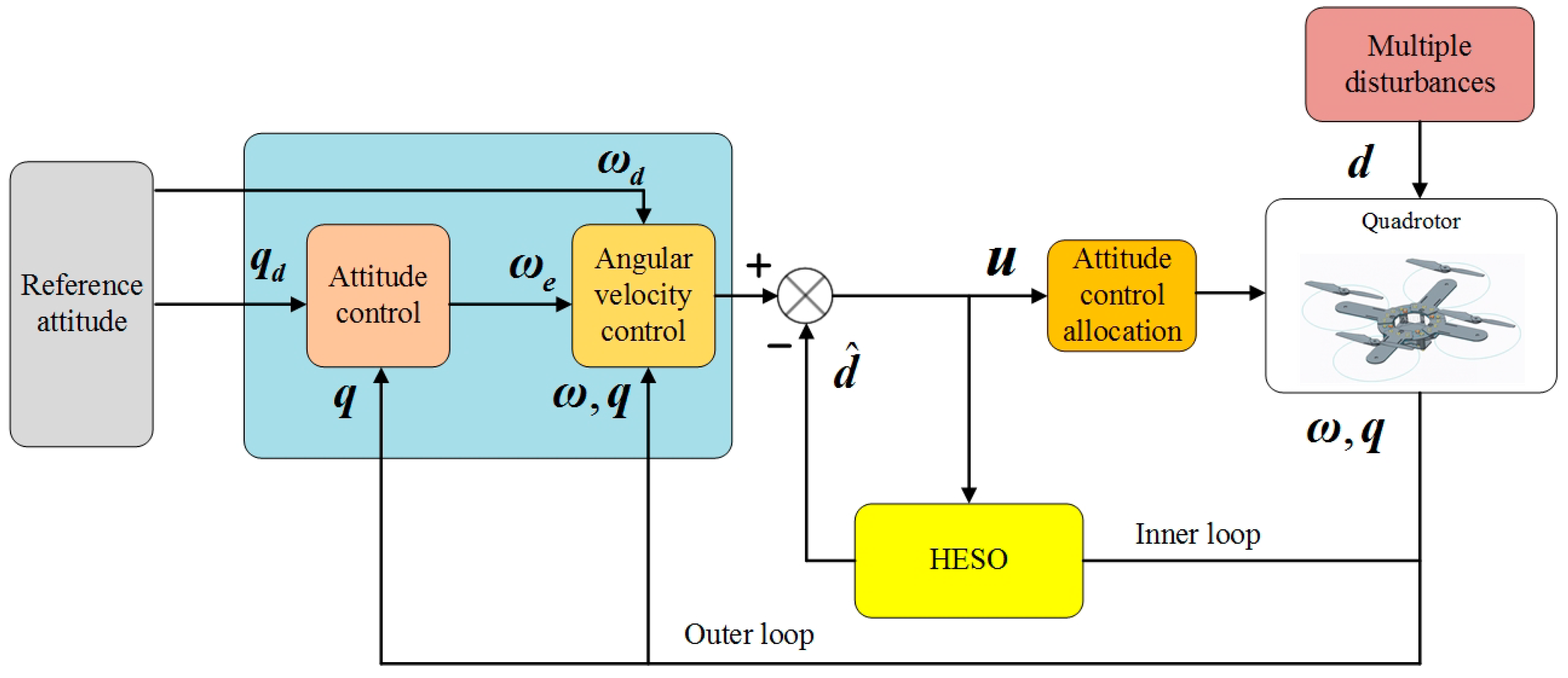
4. Design of Attitude Controller

In this section, the main procedures of attitude controller integrated with HESO are presented for effectively handling disturbance caused by slung load. The quadrotor UAV is an underactuated system with six DOF and four control inputs. In order to derive its model, backstepping method is used in the design of attitude controller.
Step 1. Design the control strategy to ensure that q e ( t ) converges to zero.
According to the attitude error kinematics subsystem Equation (29), we select the candidate Lyapunov function as:
V 1 = q e T q e + ( 1 q 0 e ) 2 > 0
Take the time derivative of V 1 , we have:
V ˙ 1 = 2 q v e T q ˙ v e 2 ( 1 q 0 e ) q ˙ 0 e = ( q v e T S ( q v e ) + q 0 e q v e T I 3 + ( 1 q 0 e ) q v e T ) ω e = q v e T ω e
Then, we design a virtual control scheme as:
ω e d = K 1 q e
where K 1 is the gain matrix of the controller, which is diagonal positive definite. If the angular velocity tracking error ω e is equal to the virtual control input ω e d , V ˙ 1 is negative semidefinite definite:
V ˙ 1 = q e T K 1 q e
According to the Lyapunov stability theorem, we can conclude that q e converges to zero, under the condition that the virtual control ω e converges to K 1 q e .
Step 2. Design the control signal u to ensure that ω e track the desired virtual control input ω e d .
We define the error between ω e and ω e d as:
ω ˜ e = ω e + K 1 q e
In order to discuss the stability of the entire system including DUE and FC, we define the following candidate Lyapunov function V 2 as:
V 2 = V 1 + 1 2 ω ˜ e T J 0 ω ˜ e + V 0 , ϕ + V 0 , θ = [ q e T q e + ( 1 q 0 e ) 2 ] + 1 2 ω ˜ e T J 0 ω ˜ e + x ˜ ϕ T P 0 x ˜ ϕ + x ˜ θ T P 0 x ˜ θ
Take the time derivative of V 2 , and substitute Equations (28), (45), and (47) into V ˙ 2 , then we have
V ˙ 2 = q v e T ω ˜ e q v e T K 1 q v e + ω ˜ e T ( J 0 ω ˙ e + J 0 K 1 q ˙ v e ) k 0 x ˜ ϕ T x ˜ ϕ + 2 x ˜ ϕ T P 0 δ ϕ k 0 x ˜ θ T x ˜ θ + 2 x ˜ θ T P 0 δ θ = q v e T K 1 q v e + ω ˜ e T ( J 0 ( S ( ω d ) R D B ω d R D B ω ˙ d ) + u + d + J 0 K 1 q ˙ v e + q v e ) k 0 ( x ˜ ϕ T x ˜ ϕ + x ˜ θ T x ˜ θ ) + 2 ( x ˜ ϕ T P 0 δ ϕ + x ˜ θ T P 0 δ θ )
Define the nominal control input vector as:
u = J 0 ( S ( ω d ) R D B ω d R D B ω ˙ d ) J 0 K 1 q ˙ v e q v e K 2 ω ˜ e d ^
where d ^ = [ C d ζ ^ ϕ C d ζ ^ θ 0 ] T is the estimation results of disturbance. Then, plug Equations (40) and (48) into Equation (47):
V ˙ 2 = q v e T K 1 q v e k 0 ( x ˜ ϕ T x ˜ ϕ + x ˜ θ T x ˜ θ ) ω ˜ e T K 2 ω ˜ e + ω ˜ e T d ˜ + 2 ( x ˜ ϕ T P 0 δ ϕ + x ˜ θ T P 0 δ θ ) λ min ( K 1 ) q v e 2 k 0 ( x ˜ ϕ 2 + x ˜ θ 2 ) λ min ( K 2 ) ω ˜ e 2 + ω ˜ e d ˜ + 2 σ λ max ( P 0 ) ( x ˜ ϕ + x ˜ θ ) λ min ( K 1 ) q v e 2 k 0 ( x ˜ ϕ 2 + x ˜ θ 2 ) λ min ( K 2 ) ω ˜ e 2 + 3 ω ˜ e ( x ˜ ϕ + x ˜ θ ) + 2 σ λ max ( P 0 ) ( x ˜ ϕ + x ˜ θ ) λ min ( K 1 ) q v e 2 ( k 0 3 2 ) ( x ˜ ϕ 2 + x ˜ θ 2 ) ( λ min ( K 2 ) 3 ) ω ˜ e 2 + 2 σ λ max ( P 0 ) ( x ˜ ϕ + x ˜ θ )
where d ˜ = C d ζ ˜ ϕ 2 + C d ζ ˜ θ 2 C d ζ ˜ ϕ + C d ζ ˜ θ 3 ( x ˜ ϕ + x ˜ θ ) , λ min ( K 1 ) and λ min ( K 2 ) are the minimal eigenvalue of K 1 and K 2 respectively. Define z T = ( q e T , ω ˜ e T , x ˜ ϕ T , x ˜ θ T ) as the uniformed vector of errors, and ξ = min ( λ min ( K 1 ) , λ min ( K 2 ) 3 , k 0 3 2 ) > 0 , then Equation (49) can be reduced to
V ˙ 3 ξ ( q v e 2 + ω ˜ e 2 + x ˜ ϕ 2 + x ˜ θ 2 ) + 2 σ λ 1 ( x ˜ ϕ + x ˜ θ ) ξ z 2 + 2 σ λ max ( P 0 ) z
Thus V ˙ 3 < 0 whenever z > 2 σ λ max ( P 0 ) ξ 1 . Notice that ( q e , ω ˜ e ) is a linear diffeomorphism of ( q e , ω e ) , hence ( q e , ω e ) can converge into a compact set. We can conclude that, the attitude error ( q e , ω e ) , virtual control input error ω ˜ e and the estimation error x ˜ ϕ and x ˜ θ are uniformly ultimately bounded and exponentially converges to the bounded ball B z = { z | z 2 σ λ max ( P 0 ) ξ 1 } .
In general, when we chose a larger ξ , the bounded ball B z will become smaller and consequently, z will also become smaller, so a larger ξ is preferred. However, larger ξ will lead to larger control gains which can excite the sensor noise and undesirable high frequency dynamics of the system. Thus, the tuning of controller parameters is a tradeoff between the demand of performance and the real conditions. Moreover, by improving the model accuracy of the disturbance, σ will be reduced, therefore, the accuracy of attitude control can be improved.

5. Simulation and Experimental Results

In order to evaluate the performance of the proposed HESO, simulation and real world experimental results are presented in this section.

5.1. Simulation Results

We present the numerical simulations of the proposed GESO based DUEA control strategy on a model generated by the online toolbox of Quan and Dai [32], and the values of the nominal model parameters are list in Table 1.
The values of gain parameters used in our controller are given as K 1 = 7 I 3 and K 2 = 2 I 3 , and the observer gains of HESO are L e , i = [ 6 27 27 8 8 2 2 ] T . Traditional 2nd order ESO is used as the comparison, and the bandwidth is fix at 3 rad/s, the observer gain is L = [ 9 27 27 ] T .

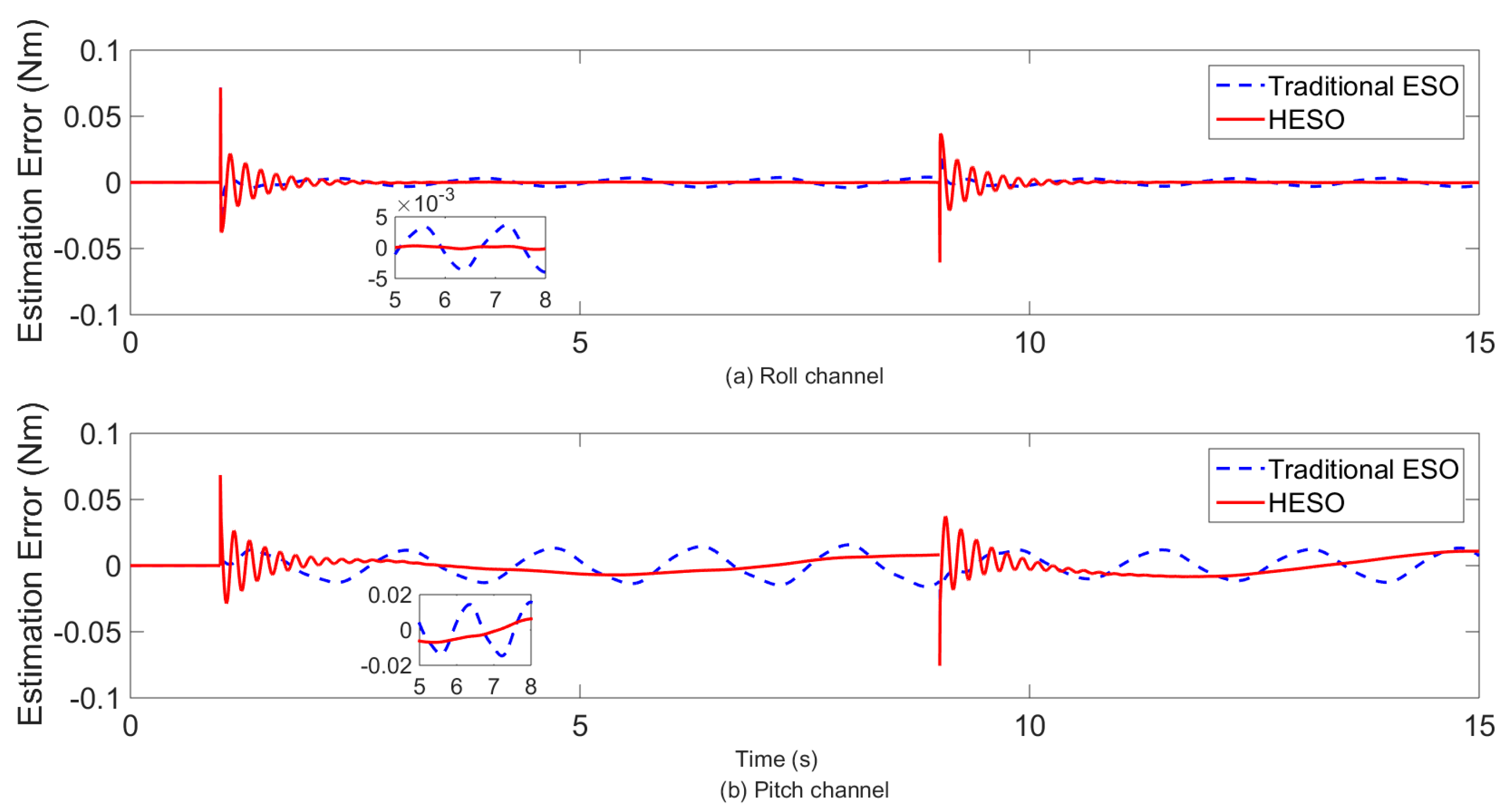
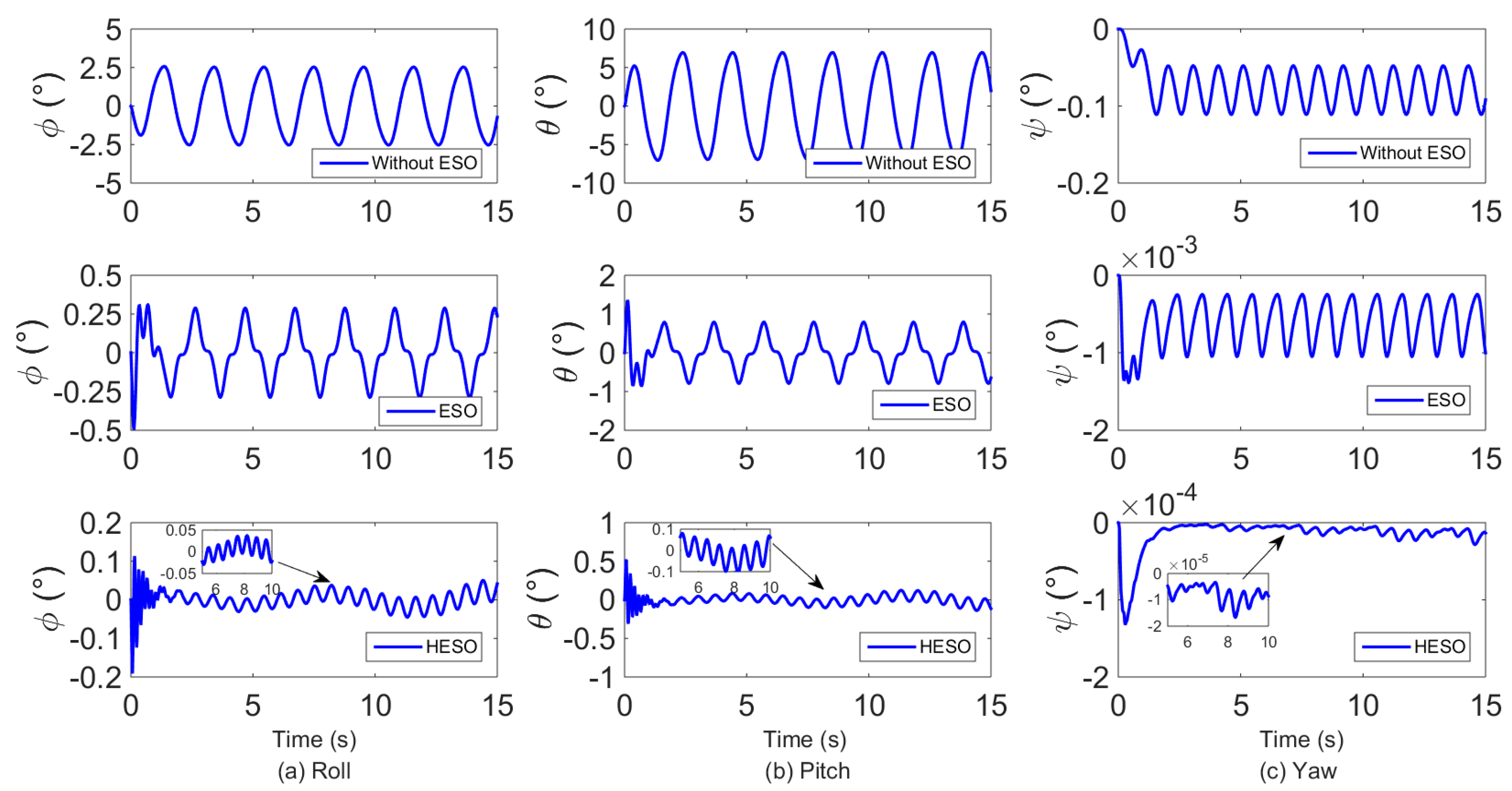
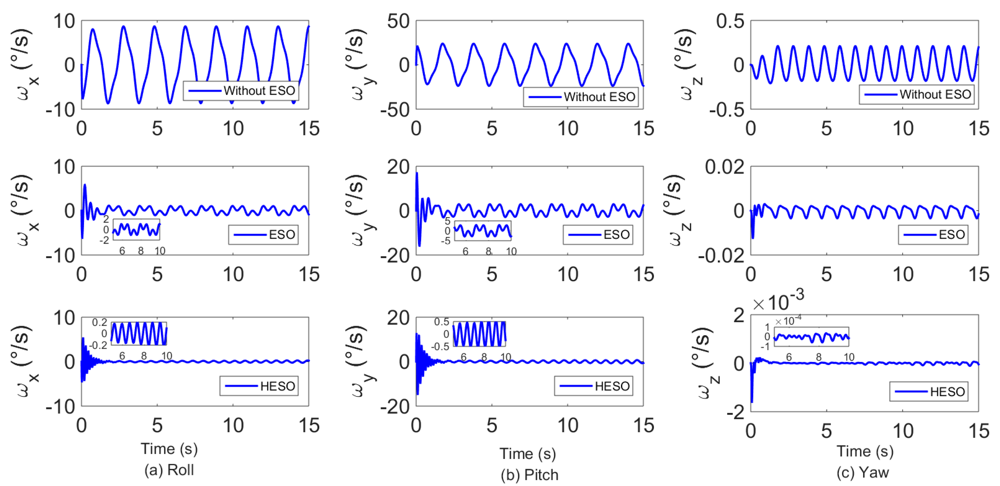
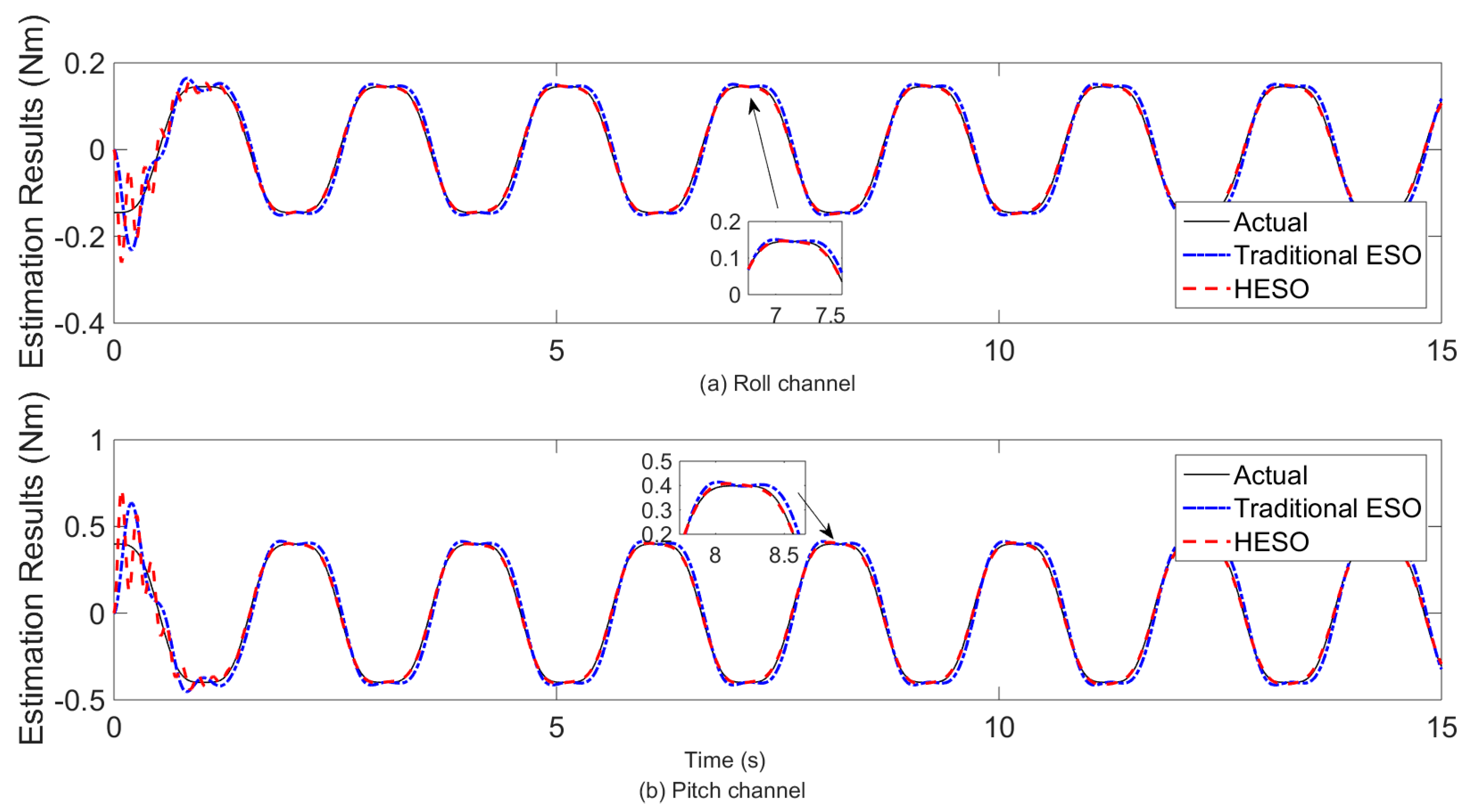
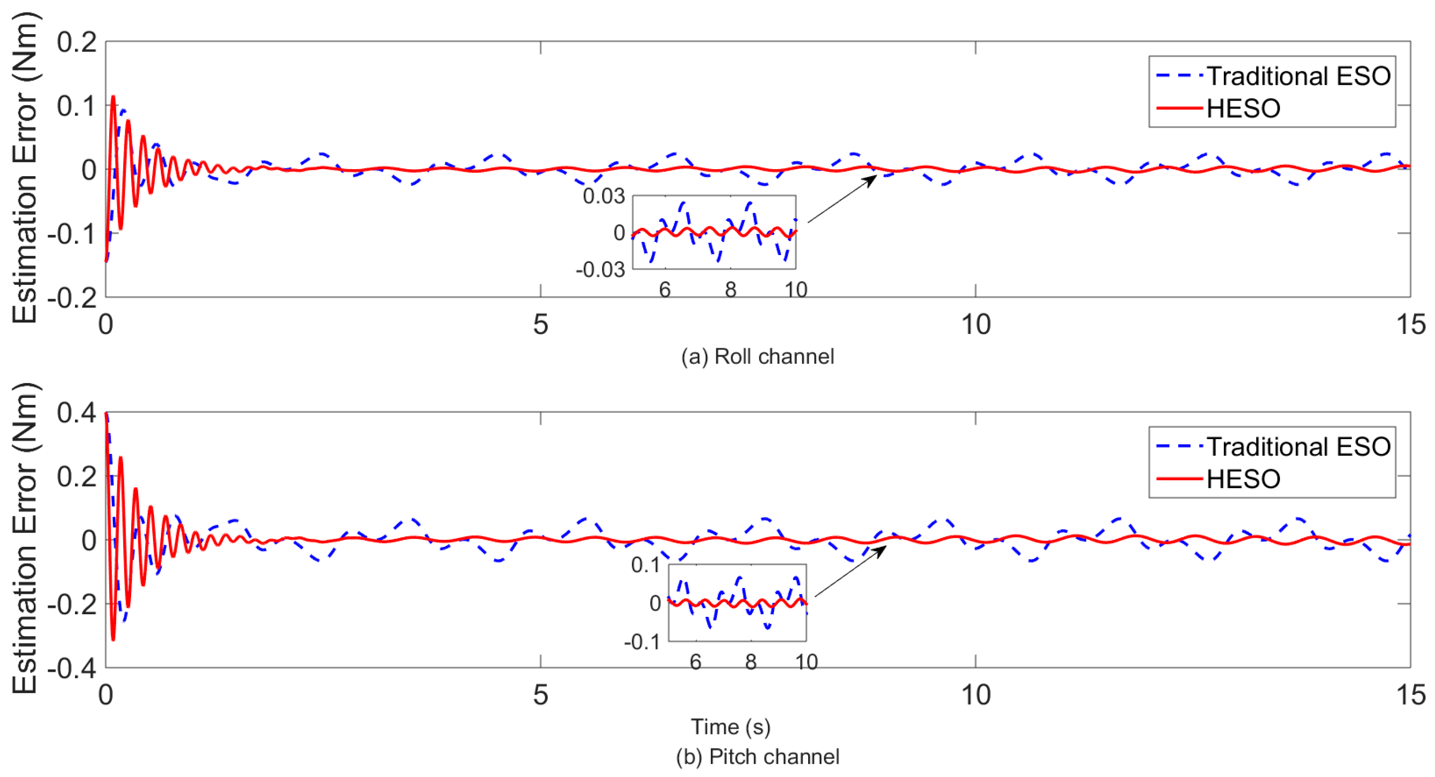
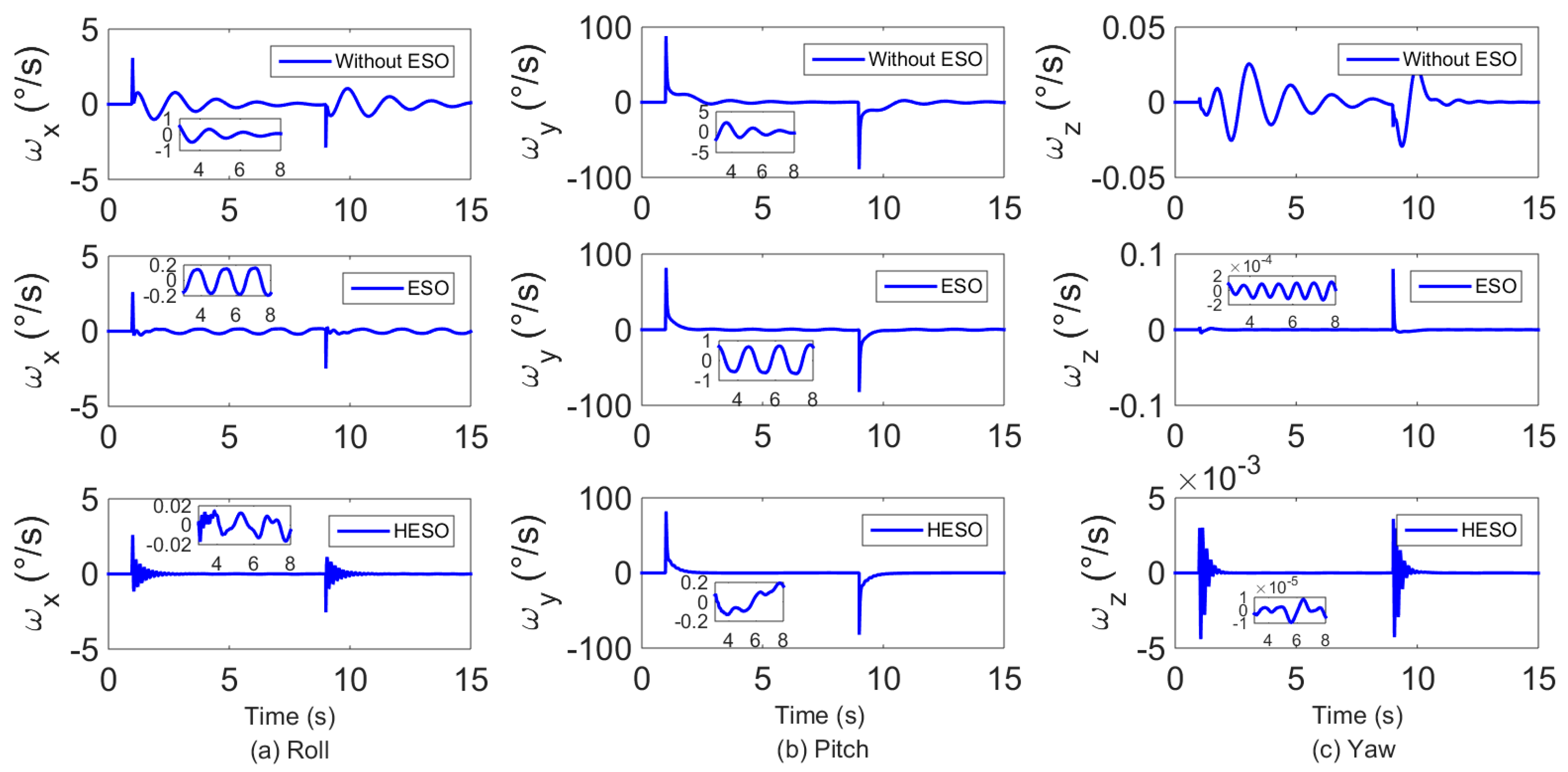
5.1.1. Comparison in Attitude Stabilization Performance

This part involves attitude stabilization control in the presence of slung load. The initial condition of the slung load is γ 0 = 30 and β = 20 . The initial conditions used of the quadrotor in the simulation are zero, and we select the desired attitude signal as follows Ω d = [ 0 0 0 ] T .
Three comparative simulations were conducted, and the performances of the proposed controller with different ESOs are compared in pitch and roll channel. Figure 3 and Figure 4 show the curves of the vehicle’s attitude response during its flight. We can see that although the proposed controller (without GESO) was able to ensure the stabilization of the attitude angles, the control accuracy was reduced under the influence of the slung load motion. When we introduced Traditional 2nd order ESO and HESO as the DUE, the performances of the proposed controller were improved, and through the comparison of attitude control results, we can conclude that HESO performed better than traditional ESO. Moreover, Figure 5 and Figure 6 show the disturbance estimation result of HESO and Traditional ESO. Obviously, we can see that the estimation error decreases when we adopt HESO.

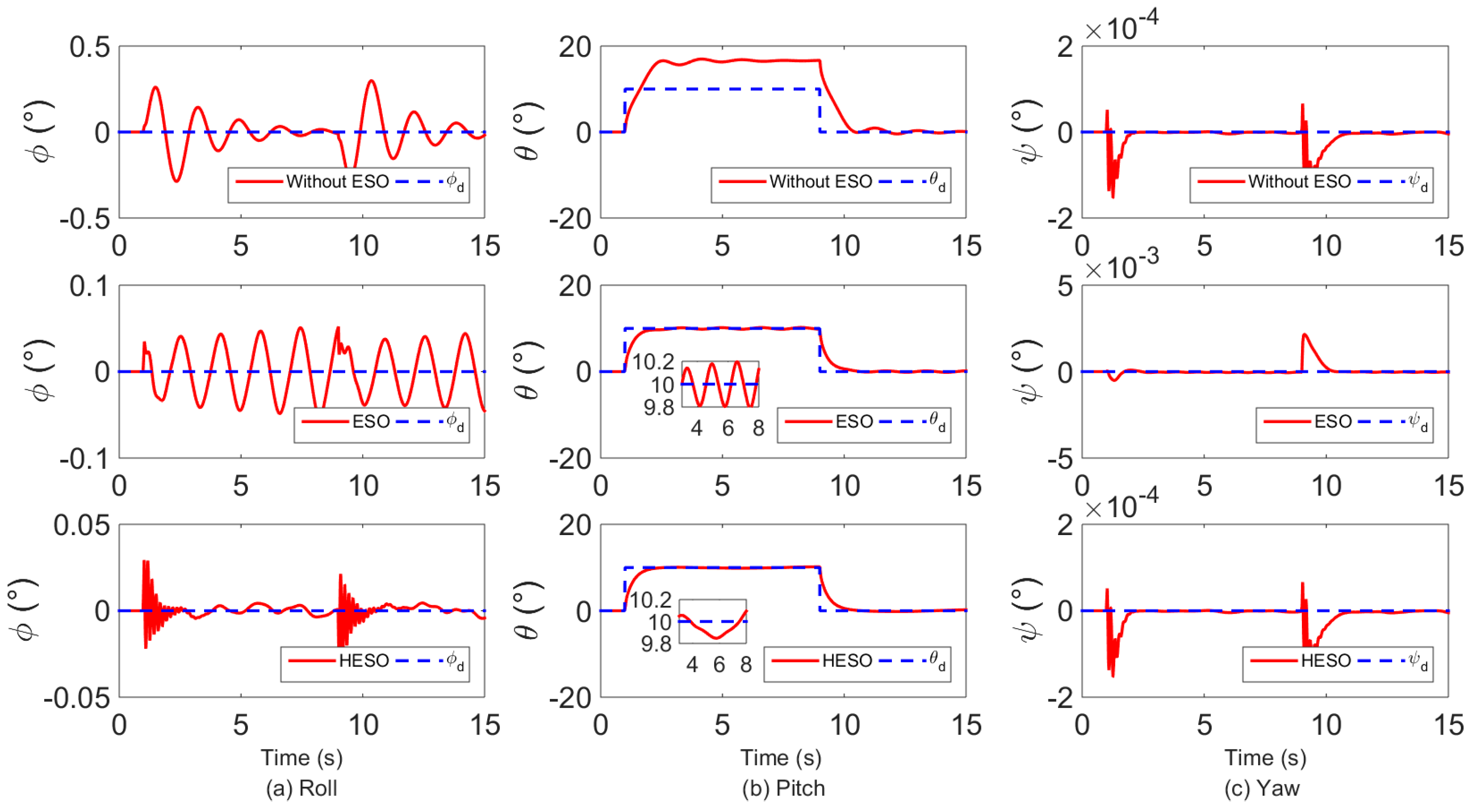
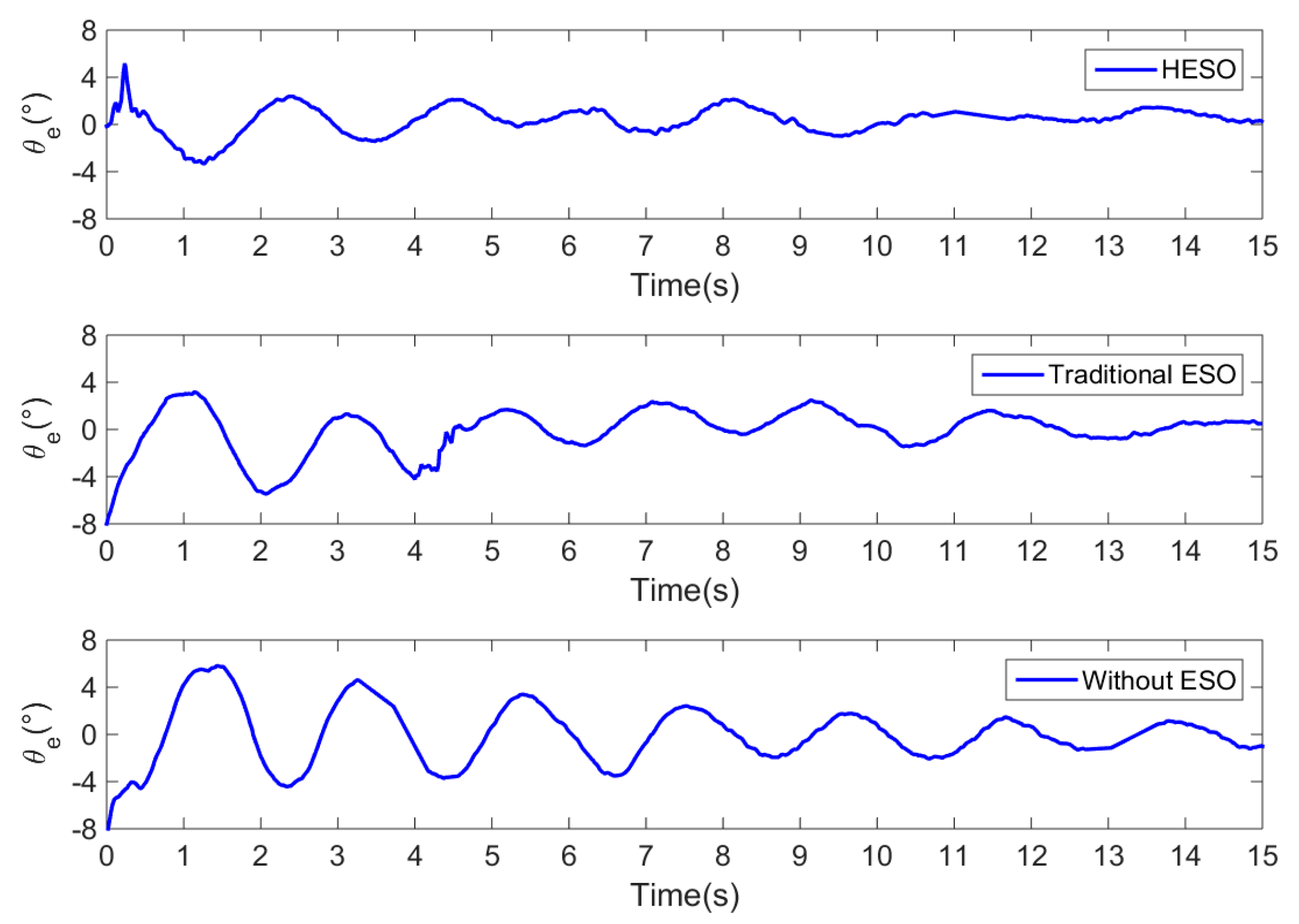
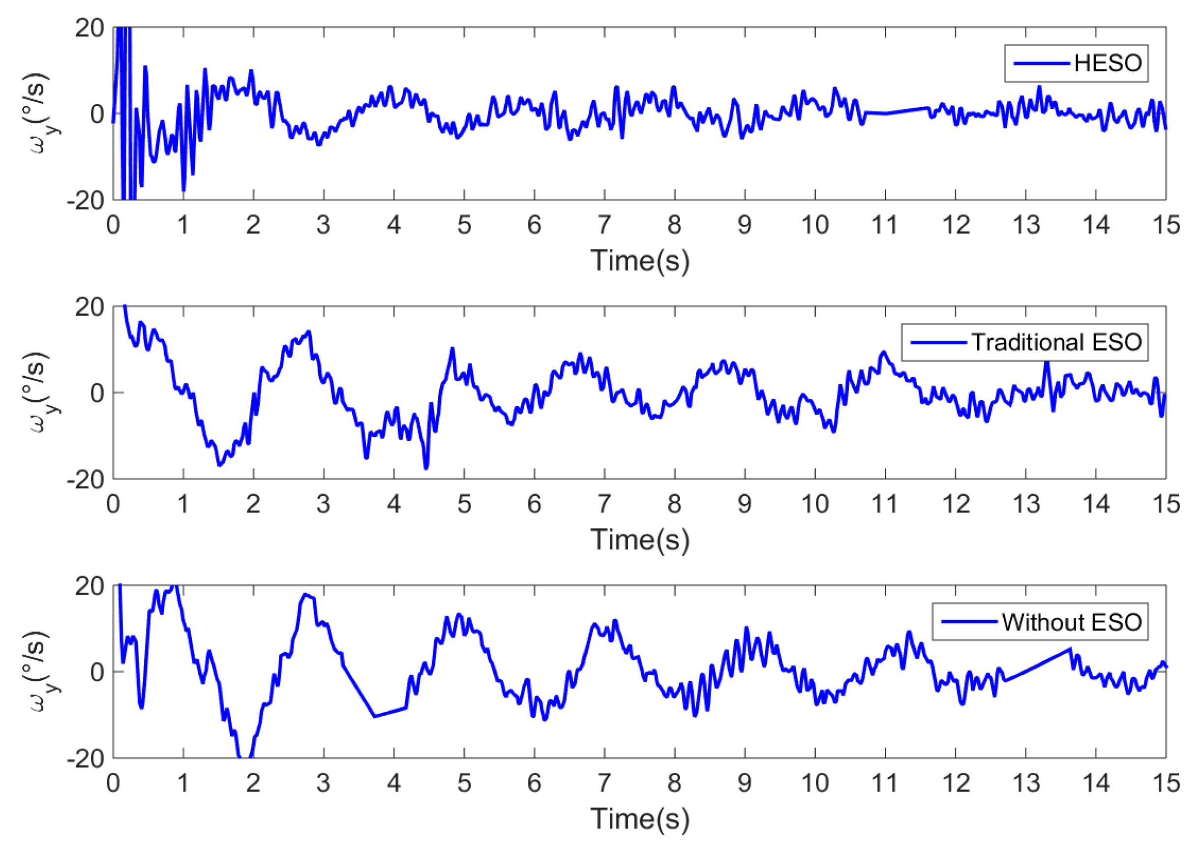
5.1.2. Comparison in Attitude Tracking Performance

In this case, the numerical simulation demonstrates the effectiveness of the proposed control scheme for attitude tracking. The initial condition of the slung load is γ 0 = 0 . We chose desired attitude signal as ϕ d = 0 and
θ d = { 10 , 1 < t < 9 0 , 0 < t 1 9 t
The attitude tracking performances of the proposed controller with different ESOs are illustrated in Figure 7 and Figure 8. We can see that the proposed controller alone was hard to ensure the tracking of the desired attitude angles, and the control accuracy was severely affected by the slung load. When we introduced Traditional 2nd ESO and HESO as the DUE, the performances of the proposed controller were improved, and the simulation results show that HESO performed better than traditional ESO. Moreover, as shown in Figure 9, we can see that the estimation error decreases when we adopt HESO.

5.2. Experimental Results

We have also tested the proposed control scheme on a self-assembled GF360 quadrotor, and PIXHAWK [33,34] was used as the autopilot of the quadrotor. To evaluate the stability and robustness of the proposed control scheme, the experiments were carried out as follows. The weight of the slung load m l is 0.5 kg and cable length L c is 1 m, the distance between the hook of the cable and the mass center of quadrotor c is about 20 cm.
Subject to the sampling frequency and noise of MEMS gyro, the observer gain of HESO is chosen as L e = [ 6 ¦   12 8 ¦   12 8 ¦   2 2 ] T . And subject to the limitations of computing power, HESO is only used in pitch channel, and the slung load only swing in longitudinal plane. The controller gains were chosen as K 1 = diag [ 7 7 2.8 ] and K 2 = diag [ 0.15 0.15 0.2 ] . Three comparative experiments with different ESO are presented.
Figure 10 presents the history of pitch angle tracking errors θ e = θ θ d obtained by the proposed controller with different ESO in the presence of slung load. Figure 11 shows the experiment results of pitch rate ω y in these three cases. It can be observed that the control performance is improved by HESO compared with the one without ESO and the one with traditional 2nd order ESO. In addition. The root mean square (RMS) errors obtained by proposed controller with different ESO are given in Table 2. It is illustrated that HESO can achieve 50.11% reduction on the RMS error of pitch angle.

6. Conclusions

In this paper, the problem of anti-swing attitude control for quadrotor in the presence of slung load is investigated. In the proposed approach, we developed a HESO based DUEA control scheme to accurately attenuate the disturbance torque caused by slung load. Through the analysis of the quadrotor-slung load system, the external disturbance torque can be described as a periodic function with two frequencies ϖ 1 = g L c 1 , ϖ 2 = 3 g L c 1 , while the amplitude and phase are unknown. Then the harmonic extended state observer is designed according to the model of the disturbance in propose of enhancing the robustness of feedback nonlinear controller. Subsequently, an attitude tracking controller is designed based on the backstepping method. From the simulation and experimental results, we can conclude that compared to the traditional 2nd order ESO, the HESO can achieve a better performance in estimating the periodic disturbances, so that the robustness of the proposed controller can be further improved.

Author Contributions

Formal analysis, D.S.; Project administration, Z.W. and W.C.; Software, D.S.; Supervision, Z.W.

Acknowledgments

This work was supported by the State Key Development Program for Basic Research of China (Grant No. 2013CB035503).

Conflicts of Interest

The authors declare no conflicts of interest.

References

  1. Bouabdallah, S.; Becker, M.; Siegwart, R. Autonomous miniature flying robots: Coming soon! IEEE Robot. Autom. Mag. 2007, 14, 88–98. [Google Scholar] [CrossRef]
  2. Satici, A.C.; Poonawala, H.; Spong, M.W. Robust optimal control of quadrotor uavs. IEEE Access 2013, 1, 79–93. [Google Scholar] [CrossRef]
  3. Stepaniak, M.J.; van Graas, F.; de Haag, M.U. Design of an electric propulsion system for a quadrotor unmanned aerial vehicle. J. Aircr. 2009, 46, 1050–1058. [Google Scholar] [CrossRef]
  4. Gupte, S.; Mohandas, P.I.T.; Conrad, J.M. A survey of quadrotor unmanned aerial vehicles. In Proceedings of the IEEE Southeastcon, Orlando, FL, USA, 15–18 March 2012. [Google Scholar]
  5. Ozbek, N.S.; Onkol, M.; Efe, M.O. Feedback control strategies for quadrotor-type aerial robots: A survey. Trans. Inst. Meas. Control 2016, 38, 529–554. [Google Scholar] [CrossRef]
  6. Bisgaard, M.; la Cour-Harbo, A.; Bendtsen, J.D. Adaptive control system for autonomous helicopter slung load operations. Control Eng. Pract. 2010, 18, 800–811. [Google Scholar] [CrossRef]
  7. Omar, H.M. Designing anti-swing fuzzy controller for helicopter slung-load system near hover by particle swarms. Aerosp. Sci. Technol. 2013, 29, 223–234. [Google Scholar] [CrossRef]
  8. Feng, Y.; Rabbath, C.A.; Rakheja, S.; Su, C.Y. Adaptive controller design for generic quadrotor aircraft platform subject to slung load. In Proceedings of the IEEE 28th Canadian Conference on Electrical and Computer Engineering (CCECE), Halifax, NS, Canada, 3–6 May 2015; pp. 1135–1139. [Google Scholar]
  9. Huang, M.; Xian, B.; Diao, C.; Yang, K.Y.; Feng, Y. Adaptive tracking control of underactuated quadrotor unmanned aerial vehicles via backstepping. In Proceedings of the American Control Conference (ACC), Baltimore, MD, USA, 30 June–2 July 2010; pp. 2076–2081. [Google Scholar]
  10. Alexis, K.; Nikolakopoulos, G.; Tzes, A. Model predictive quadrotor control: Attitude, altitude and position experimental studies. IET Control Theory Appl. 2012, 6, 1812–1827. [Google Scholar] [CrossRef]
  11. Sadr, S.; Moosavian, S.A.A.; Zarafshan, P. Dynamics modeling and control of a quadrotor with swing load. J. Robot. 2014, 2014, 265897. [Google Scholar] [CrossRef]
  12. Palunko, I.; Cruz, P.; Fierro, R. Agile load transportation: Safe and efficient load manipulation with aerial robots. IEEE Robot. Autom. Mag. 2012, 19, 69–79. [Google Scholar] [CrossRef]
  13. De Crousaz, C.; Farshidian, F.; Neunert, M.; Buchli, J. Unified motion control for dynamic quadrotor maneuvers demonstrated on slung load and rotor failure tasks. In Proceedings of the IEEE International Conference on Robotics and Automation (ICRA), Seattle, WA, USA, 26–30 May 2015; pp. 2223–2229. [Google Scholar]
  14. Guerrero-Sanchez, M.E.; Mercado-Ravell, D.A.; Lozano, R.; Garcia-Beltran, C.D. Swing-attenuation for a quadrotor transporting a cable-suspended payload. ISA Trans. 2017, 68, 433–449. [Google Scholar] [CrossRef] [PubMed]
  15. Wang, H.D.; Huang, Y.B.; Xu, C. Adrc methodology for a quadrotor uav transporting hanged payload. In Proceedings of the IEEE International Conference on Information and Automation (ICIA), Ningbo, China, 1–3 August 2016; pp. 1641–1646. [Google Scholar]
  16. Chen, W.H.; Ohnishi, K.; Guo, L. Advances in disturbance/uncertainty estimation and attenuation. IEEE Trans. Ind. Electron. 2015, 62, 5758–5762. [Google Scholar] [CrossRef]
  17. Yang, J.; Chen, W.H.; Li, S.H.; Guo, L.; Yan, Y.D. Disturbance/uncertainty estimation and attenuation techniques in pmsm drives-a survey. IEEE Trans. Ind. Electron. 2017, 64, 3273–3285. [Google Scholar] [CrossRef]
  18. Wang, Z.; Wu, Z. Nonlinear attitude control scheme with disturbance observer for flexible spacecrafts. Nonlinear Dyn. 2015, 81, 257–264. [Google Scholar] [CrossRef]
  19. Wang, Z.; Wu, Z.; Du, Y.J. Adaptive sliding mode backstepping control for entry reusable launch vehicles based on nonlinear disturbance observer. Proc. Inst. Mech. Eng. Part G J. Aerosp. Eng. 2016, 230, 19–29. [Google Scholar] [CrossRef]
  20. Pu, Z.Q.; Yuan, R.Y.; Yi, J.Q.; Tan, X.M. A class of adaptive extended state observers for nonlinear disturbed systems. IEEE Trans. Ind. Electron. 2015, 62, 5858–5869. [Google Scholar] [CrossRef]
  21. Xia, Y.Q.; Pu, F.; Li, S.F.; Gao, Y. Lateral path tracking control of autonomous land vehicle based on adrc and differential flatness. IEEE Trans. Ind. Electron. 2016, 63, 3091–3099. [Google Scholar] [CrossRef]
  22. Busawon, K.K.; Kabore, P. Disturbance attenuation using proportional integral observers. Int. J. Control 2001, 74, 618–627. [Google Scholar] [CrossRef]
  23. Gao, Z.W.; Breikin, T.; Nang, H. Discrete-time proportional and integral observer and observer-based controller for systems with both unknown input and output disturbances. Optim. Control Appl. Methods 2008, 29, 171–189. [Google Scholar] [CrossRef]
  24. Han, J.Q. From pid to active disturbance rejection control. IEEE Trans. Ind. Electron. 2009, 56, 900–906. [Google Scholar] [CrossRef]
  25. Wang, W.W.; Gao, Z.Q. A comparison study of advanced state observer design techniques. In Proceedings of the 2003 American Control Conference, Denver, CO, USA, 4–6 June 2003; pp. 4754–4759. [Google Scholar]
  26. Madonski, R.; Herman, P. Survey on methods of increasing the efficiency of extended state disturbance observers. ISA Trans. 2015, 56, 18–27. [Google Scholar] [CrossRef] [PubMed]
  27. Godbole, A.A.; Kolhe, J.P.; Talole, S.E. Performance analysis of generalized extended state observer in tackling sinusoidal disturbances. IEEE Trans. Control Syst. Technol. 2013, 21, 2212–2223. [Google Scholar] [CrossRef]
  28. Zhang, Y.J.; Zhang, J.; Wang, L.; Su, J.B. Composite disturbance rejection control based on generalized extended state observer. ISA Trans. 2016, 63, 377–386. [Google Scholar] [CrossRef] [PubMed]
  29. Chen, W.H. Harmonic disturbance observer for nonlinear systems. J. Dyn. Syst. Meas. Control 2003, 125, 114–117. [Google Scholar] [CrossRef]
  30. Chovancova, A.; Fico, T.; Hubinsky, P.; Duchon, F. Comparison of various quaternion-based control methods applied to quadrotor with disturbance observer and position estimator. Robot. Auton. Syst. 2016, 79, 87–98. [Google Scholar] [CrossRef]
  31. Bouabdallah, S.; Siegwart, R. Full control of a quadrotor. In Proceedings of the IEEE/RSJ International Conference on Intelligent Robots and Systems, San Diego, CA, USA, 29 October–2 November 2007; pp. 153–158. [Google Scholar]
  32. Quan, Q.; Dai, X. Flight Performance Evaluation of Uavs. Available online: http://flyeval.com/ (accessed on 20 April 2018).
  33. Meier, L.; Tanskanen, P.; Heng, L.; Lee, G.H.; Fraundorfer, F.; Pollefeys, M. Pixhawk: A micro aerial vehicle design for autonomous flight using onboard computer vision. Auton. Robot. 2012, 33, 21–39. [Google Scholar] [CrossRef]
  34. Meier, L.; Tanskanen, P.; Fraundorfer, F.; Pollefeys, M. The pixhawk open-source computer vision framework for mavs. Int. Arch. Photogramm. 2011, 38, 13–18. [Google Scholar] [CrossRef]
Figure 1. Quadrotor-slung load system geometry and coordinate systems.
Electronics 07 00083 g001
Figure 2. Block diagram of the proposed control scheme.
Electronics 07 00083 g002
Figure 3. Simulation curves of the attitude angle in attitude stabilization: (a) roll channel; (b) pitch channel; (c) yaw channel.
Electronics 07 00083 g003
Figure 4. Simulation curves of the attitude rate in attitude stabilization: (a) roll channel; (b) pitch channel; (c) yaw channel.
Electronics 07 00083 g004
Figure 5. Estimation results comparison of harmonic extended state observer (HESO) and traditional extended state observer (ESO) in attitude stabilization.
Electronics 07 00083 g005
Figure 6. Estimation errors comparison of HESO and traditional ESO in attitude stabilization.
Electronics 07 00083 g006
Figure 7. Simulation curves of the attitude angle in attitude tracking: (a) roll channel; (b) pitch channel; (c) yaw channel.
Electronics 07 00083 g007
Figure 8. Simulation curves of the attitude rate in attitude tracking: (a) roll channel; (b) pitch channel; (c) yaw channel.
Electronics 07 00083 g008
Figure 9. Estimation errors comparison of HESO and traditional ESO in attitude tracking.
Electronics 07 00083 g009
Figure 10. Experimental curves of θ with different ESO.
Electronics 07 00083 g010
Figure 11. Experimental curves of ωy with different ESO.
Electronics 07 00083 g011
Table 1. Quadrotor parameters used in simulation.
ParameterDescriptionValue
mqMass of the quadrotor2 kg
mlMass of the slung load1 kg
cHook position0.2 m
LcLength of the cable1 m
JxRoll inertia1.335 × 10−2 kg·m2
JyPitch inertia1.335 × 10−2 kg·m2
JzYaw inertia2.465 × 10−2 kg·m2
lMotor moment arm0.18 m
gGravity acceleration9.81 g·s2
kTAerodynamic coefficient8.54 × 10−6 kg·m
kDDrag coefficient1.36 × 10−7 kg·m2
Table 2. Comparison of control performance in the tracking error of pitch angle with different ESO (RMS error).
Without ESOTraditional ESOHESO
θe (°)2.46961.88901.2320

