Super-Twisting Extended State Observer and Sliding Mode Controller for Quadrotor UAV Attitude System in Presence of Wind Gust and Actuator Faults


1
School of Instrumentation Science and Optoelectronics Engineering, Beihang University, Beijing 100191, China
2
School of Mechanical Engineering and Automation, Beihang University, Beijing 100191, China
3
State Key Laboratory of Virtual Reality Technology and System, Beijing 100191, China
*
Author to whom correspondence should be addressed.
Electronics 2018, 7(8), 128; https://doi.org/10.3390/electronics7080128
Submission received: 19 June 2018
/
Revised: 9 July 2018
/
Accepted: 24 July 2018
/
Published: 26 July 2018
(This article belongs to the Special Issue Autonomous Control of Unmanned Aerial Vehicles)
Abstract
:This article addresses the problem of high precision attitude control for quadrotor unmanned aerial vehicle in presence of wind gust and actuator faults. We consider the effect of those factors as lumped disturbances, and in order to realize the quickly and accurately estimation of the disturbances, we propose a control strategy based on the online disturbance uncertainty estimation and attenuation method. Firstly, an enhanced extended state observer (ESO) is constructed based on the super-twisting (ST) algorithm to estimate and attenuate the impact of wind gust and actuator faults in finite time. And the convergence analysis and parameter selection rule of STESO are given following. Secondly, in order to guarantee the asymptotic convergence of desired attitude timely, a sliding mode control law is derived based on the super-twisting algorithm. And a comprehensive stability analysis for the entire system is presented based on the Lyapunov stability theory. Finally, to demonstrate the efficiency of the proposed solution, numerical simulations and real time experiments are carried out in presences of wind disturbance and actuator faults.
1. Introduction
Quadrotor unmanned aerial vehicles (UAVs) are rapidly growing in popularity due to their wide range of civil and military applications such as surveillance, inspection, search and rescue, and disaster response. As a new kind of UAV, quadrotor is a small rotorcraft with four propellers driven by four direct current (DC) motors respectively [1]. Compared with traditional helicopters, the structure of quadrotor is simpler and more efficient, and has unique features in precise hovering, aggressive maneuver, vertical take-off and landing (VTOL) [2,3], etc. Therefore, the researches on quadrotor unmanned aerial vehicle become more and more popular in recent years, and a lot of achievements have been made [4,5,6].
The quadrotor is an underactuated and nonlinear coupled system [7]. Traditionally, the integral-type control methods are commonly used in the controller design of quadrotor UAVs and have shown to be effective in the attitude and position stabilization control of them. In [8,9], a proportional integral derivative (PID) control method was developed to obtain the stability of quadrotor. In [10], nonlinear PI/PID controller was designed to regulate the posture of quadrotor and showed robustness to aircraft systems effects. In [11], a motion controller of quadrotor has been derived by using time scale separation ideas, and numerical simulations confirmed that the motion control objective is satisfied with the proposed scheme in presence of the forces saturation of propellers, sensor noise and perturbing forces caused by wind. And in [12], the linear quadratic regulator (LQR) controller was applied to deal with the nominal system of quadrotor obtained by feedback linearization method. In order to meet some mission requirements, high precision attitude control is essential in those applications. However, when operating in outdoor environments, quadrotors would be easily affected by wind gust during the course of flight [13]. In addition to wind gust, the actuating motor-propeller system is prone to faults due to component degradation or damage to the motors or propellers, which may lead to significant performance degradation or even instability of the close-loop system [14]. Therefore, it is difficult for the traditional linear controllers to achieve the high precision control requirement under the influence of these factors. To solve this problem, many approaches have been proposed in literatures. Robust adaptive controller was introduced to eliminate the influence of wind gust in [15]. In [16], robust optimal backstepping control (ROBC) is designed to address the stabilization and trajectory tracking problem of quadrotor in the existence of wind gust. And in [14], a nonlinear robust adaptive fault-tolerant altitude and attitude tracking method was implemented to accommodating actuator faults in quadrotor without the need of a faults diagnosis mechanism. In summery, these methods were designed to improve the robustness of the system.
Alternatively, both wind gust and actuator faults can be considered as lumped disturbances and the online disturbance and uncertainty estimation and attenuation (DUEA) method would be a potential solution to this problem. In recent years, the DUEA methods have been widely studied for some types of real time systems in order to cancel the influence of lumped disturbances at the controller stage [17,18], and the framework of which can be divided into two parts, namely, a disturbance and uncertainty estimator (DUE) and a feedback controller (FC).
In the first part, DUE is designed to estimate the disturbances so that they could be compensated in the feedforward loop. To achieve this aim, a series of observers have been proposed as the DUE so far, such as disturbance observer (DO) [19,20], extended state observer (ESO) [21,22,23,24], proportional integral observer (PIO) [25,26] and acceleration based disturbance observer (ABDOB) [27], etc. By the appropriate use of the observer, disturbance rejection performance and robustness of the existing control system could be significantly improved. The extended state observer (ESO), known as the key module of active disturbance rejection control, can estimate both the states of system and the total disturbances with less dependence on model information [28,29]. This method was first proposed by Han in 1990s and the basic idea behind ESO is to view disturbance as an extended state and utilize observer to estimate it [28]. As for the ESO based control structure, the performance of closed-loop system is largely determined by the estimation accuracy of observer. The traditional ESO approaches focus primarily on dealing with slowly changing disturbances. However, it’s obvious that the disturbance torque caused by the wind gust and actuator faults happens suddenly, which can not be estimated by traditional ESO thoroughly [30]. Therefore, an enhanced ESO that can quickly estimate the disturbance is necessary in this field. In [31], a higher-order ESO is investigated and the estimation accuracy was improved, however, higher level of the observer order will lead to a higher observer gain which will in return excite the sensor noise and introduce them into the control loop. In [32], a sliding model method was used in disturbance observer to estimate the quadrotor velocities, the external disturbances such as wind and parameter uncertainties, and achieves good results, except for serious chattering. To reduce this problem, super-twisting algorithm have been adopted in design of the observer. In [33], the super-twisting observer (STO) is constructed to reject aperiodic disturbances and input unmatched periodic disturbances with reduced chattering.
In the second part, the FC is designed to guarantee fast convergence of the closed-loop system. Sliding mode control (SMC) has been known as one of the most efficiency controller in fast convergence [34]. In [35], a fixed-time second-order sliding mode control law is designed to guarantee the reaching time, independent of initial conditions. However, the robustness of the SMC is achieved at the cost of a high frequency switching of the control signal, which has a negative effect in the actuator. To reduce the chattering, a family of continuous sliding mode controllers based on super-twisting algorithm have been developed [36].
Motivated by the above observations and inspired from Ref. [33,36], a high precision attitude control law is developed for quadrotor unmanned aerial vehicle in presence of wind gust and actuator faults. The main contributions of this paper are summarized as follows:
- Propose a STESO to accurately estimate the disturbance torque caused by wind gust and actuator faults in finite time, and give the parameter selection rule of the observer;
- Design a fast convergence attitude control law based on STSMC, and give a comprehensive stability analysis on the entire system.
The remainder of the paper is organized as follows. The mathematical model and control problem is formulated in Section 2. A STESO is designed in Section 3, as well as parament selection rule of the observer is also given in this section. In Section 4, a fast convergence attitude controller is designed based on ST algorithm. Numerical simulation and real time experimental results are presented in Section 5. Finally, we conclude the paper in Section 6.
2. Mathematical Model and Problem Formulation
2.1. Notation
denotes the 2-norm of a vector or a matrix. For a given vector , . For a given matrix , and denote the maximal and minimum eigenvalue of the matrix respectively. In addition, the operator maps a vector to a skew symmetric matrix as:
is the sign function, and for a scalar x:
For a vector and , define:
2.2. Quaternion Operations
In order to avoid the singularity problem of trigonometric functions, unit quaternion , is used to represent rotation [37] of the quadrotor. Following are the operations we used.
The quaternion multiplication is:
The relationship between rotation matrix and is calculated as:
The derivative of a quaternion is given by the quaternion multiplication of the quaternion and the angular velocity of the system :
The quaternion error is given as the quaternion multiplication of the conjugate of the actual quaternion and the desired quaternion :
2.3. Kinematics and Dynamics of Quadrotor
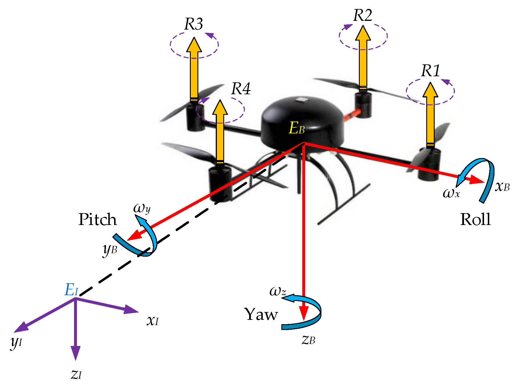
In this section, the kinematic and dynamic differential equations of the quadrotor are established. The quadrotor can be considered as a rigid cross frame attached with four rotors, and the center of gravity coincides with the body-fixed frame origin.
The simplified model of the quadrotor is presented in Figure 1, rotors and rotate counterclockwise and rotors and rotate clockwise. Each propeller rotates at the angular speed and produces a force (i = 1, 2, 3, 4) along the negative z-direction relative to the body frame [37,38]:
where denotes the aerodynamic coefficient which consists formed of the atmospheric density , the radius of the propeller r, and the thrust coefficient . In addition, due to the spinning of the rotors, a reaction torque (i = 1, 2, 3, 4) is generated on the quadrotor body by each rotor:
where denotes the drag coefficient of the rotor, which depends on the same factors as .
In the mathematical model of quadrotor, three coordinate frames are considered: the non-moving inertial frame , the body-fixed frame and the desired frame to represent the actual attitude and desired attitude of quadrotor respectively. Note that North-East-Down (NED) coordinates are used to define all frames. Attitude angle and angular velocities of the body-fixed frame with respect to the inertial frame are written as and respectively, and the quaternion expression of the attitude is .
The variation of the orientation is achieved by varying the angular speed of a specific rotor. The torque created around a particular axis with respect to the body-fixed frame is defined as follows:
where l denotes the distance from the rotors to the center of mass and represents the control signal to be designed.
Assuming a symmetric mass distribution of the quadrotor, the nominal inertia matrix is diagonal. With the disturbances caused by wind gust and actuator faults into consideration, the attitude dynamic model of the quadrotor can be obtained as the following differential equations:
According to Equation (4), we summarized the mathematical model of the quadrotor as:
In practice, we can use micro electro mechanical system (MEMS) inertial measurement unit (IMU) to measure the attitude information and .
2.4. Lumped Disturbaces
2.4.1. Wind Gust
Wing gust produces a strong disturbance torque on the quadrotor. In this article, a Dryden wind gust model is introduced [39]. We assume that the disturbance caused by wind gust is proportional to the speed of wind gust, therefore, can be described based on the random theory [40] and defined as a summation of sinusoidal excitations:
where is a time-dependent description of the wind disturbance in channel in a given time t. and are randomly selected frequencies and phase shifts, is the number of sinusoids, is the amplitude of the sinusoid, and is the static wind disturbance.
2.4.2. Actuator Faults
In this article, we consider actuator faults represented by partial loss of effectiveness in the rotors. For instance, caused by structural damage to a propeller [14], battery power loss [41], etc. Thus, the actuator faults in this article are modeled as follows, for :
where represents the commanded rotor angular velocity, is the loss of angular velocity, and is an unknown ratio characterizing the occurrence of a partial loss of effectiveness fault in rotor i with being a known upper bound needed to maintain the controllability of the quadrotor. For instance, in the extreme case of complete failure , the quadrotor becomes uncontrollable. The case of represents a healthy rotor, and represents a faulty rotor with partial loss of effectiveness.
where the fault time profile function is assumed to be a step function with unknown fault occurrence time for , that is:
In summary, we can see that the disturbances acting on quadrotor are high-order, non-Gaussian and happen suddenly, furthermore, their randomness and nonlinearity are also very strong.
2.5. Problem Formulation
The purpose of this article is to achieve the high precision tracking to the desired attitude in presence of wind gust and actuator faults. Therefore, the dynamics of attitude error should be introduced. We use and to denote the desired angular velocities and attitude respectively, thus the tracking error vector of the angular velocities can be expressed as:
Then, we can obtain the dynamics of according to Equations (3), (10) and (15):
where can be calculated according to Equations (2) and (5). And according to Equations (4), (5), and (15), we can obtain the kinematics of attitude tracking error:
Therefore, the problem we try to tackle in this work is to design a continuous control law , which guarantees errors of attitude angles and angular velocities asymptotic converge to zero in the presence of the lumped disturbances .
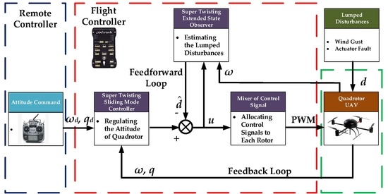
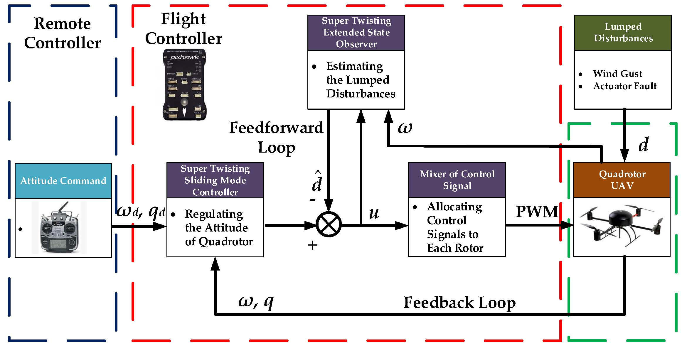
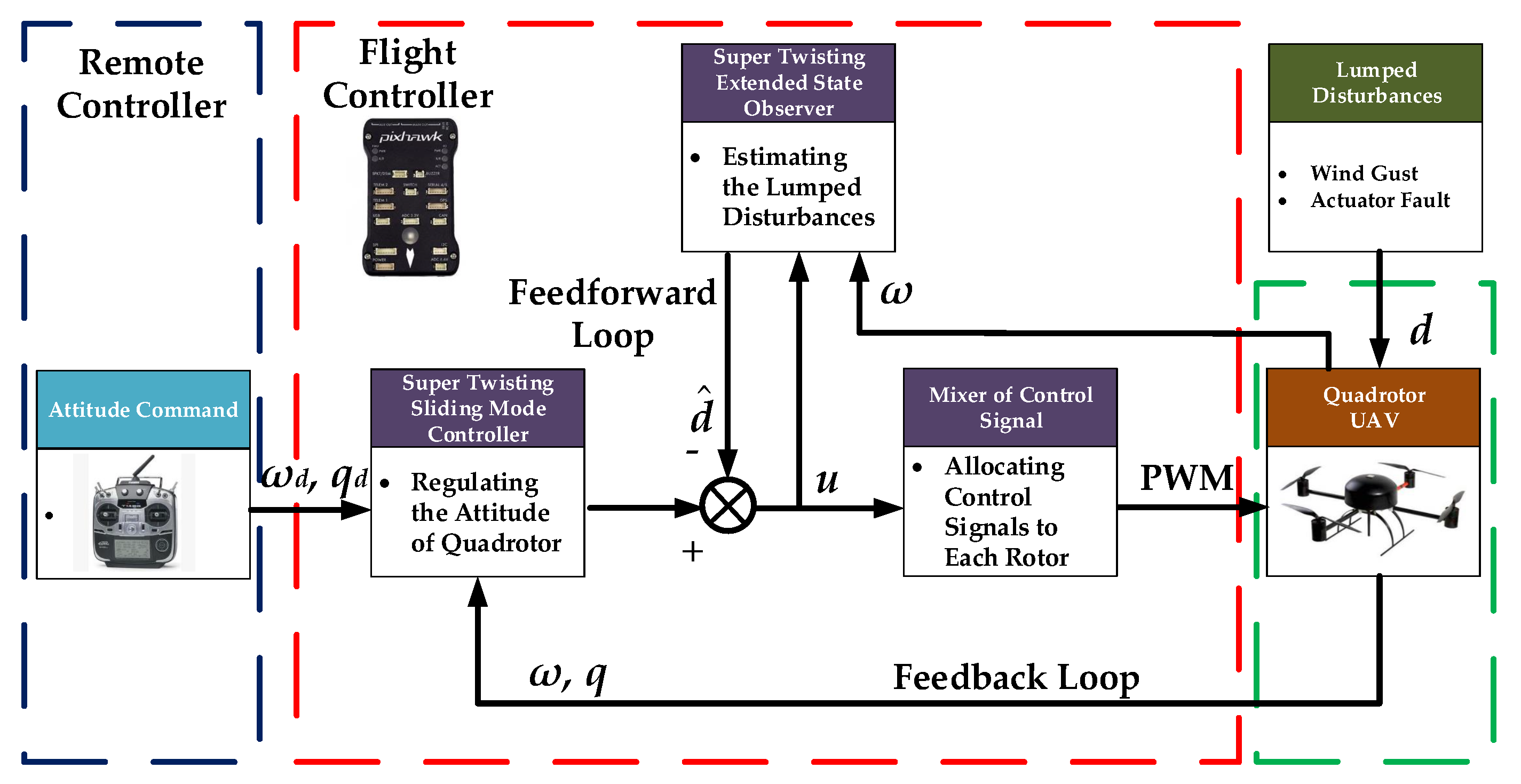
Figure 2 illustrates the control structure that we designed. Based on the DUEA control methodology, the attitude tracking problem for quadrotor can be divided into two components:
- Design the feedforward loop so that the lumped disturbances are estimated by STESO and compensated this way.
- Design the feedback loop that regulates the orientation of quadrotor to track the desired attitude produced by the commander timely.
3. Design and Analysis of Super Twisting Extended State Observer
Through the analysis in previous section, we can see that the lumped disturbances acting on quadrotor are high-order and rapidly changing, therefore, it is difficult for traditional ESO to estimate them thoroughly [30]. Higher-order ESO have been applied in some articles. However, higher observer orders will lead to higher control gains with fixed bandwidth. Which will in return excite the sensor noise and introduce them into the control loop. By introducing super twisting algorithm, excessively high observer gain can be avoided. In this section, the STESO is proposed and the convergence analysis and parameter selection rule of STESO are given.
3.1. Design of STESO
Consider the dynamics Equation (10) of quadrotor, since the angular velocities can be measured by the MEMS gyroscope, the original control input can be reformulated by employing the feedback linearization technique as:
Therefore, we can obtain the linearized model of the quadrotor as .
It is supposed that each component of the linearized model is independent from each other. Hence, the controller policy developed from one channel can be directly applied to the other two and the description of only the i-th channel is sufficient . In this way, the one-dimensional dynamic of the quadrotor is obtained as:
Introducing a new state vector whose components are defined as and augmenting lumped disturbances as an extended state , the reconstructed system is rewritten as:
where is the derivative of . Assume that the system states are bounded, then the existence of a constant is ensured such that the inequality holds for any time.
It can be verify that the pair is observable. Then, consider as the estimation of , STESO can be designed as follows:
where and are the observer gains to be designed.
Define the estimation error variables as , and the dynamics of the can be obtained as follows:
The dynamics of the estimation error, presented in Equation (22), have the form of a non-recursive exact robust differentiator. Therefore, the errors and will converge to zero in a finite time if the gains and are chosen appropriately. The convergence analysis and parameter selection rule will be demonstrated following.
3.2. Convergence Analysis and Parameter Selection Rule
Firstly, introduce a new state vector as , and take the time derivative of , we have:
which can be rewritten as:
Then, introduce a positive definite matrix and consider the following Lyapunov function:
Notice that in Equation (25), is continuous but is not differentiable at , and it is positive definite and radially unbounded if , thus we have:
Take the time derivative of and define , we have:
where and is positive defined. Notice that:
From Equation (29), we can find that is negative definite on condition that is positive definite, what is exactly the case if:
Then, analyze the finite time convergence of , according to Equation (26), we have:
Indeed, separating variables and integrating inequality Equation (32) over the time interval , we obtain:
where is the initial value of . Consequently, reaches zero in a finite time that is bounded by:
4. Design of Super Twisting Sliding Mode Controller
Sliding mode control (SMC) has been known as one of the most important tools for those systems subjected to disturbances and uncertainties, while chattering is inevitable in those methods. In order to reduce the chattering, supper twisting SMC is introduced in this section. The main objective of the FC is to guarantee that the state of attitude and converge to the reference values and timely. Thus, the sliding mode manifold in this article is chosen as follows:
where is a positive defined three dimensional coefficient matrix to be designed. Take time derivative of , we have:
Define the control signal as:
and plug Equation (38) into (37), we have:
where is the estimation error of multiple disturbances, and according to the analysis of the previous section, is bounded and converges to zero in finite time. Define as , then Equation (39) can be rewritten as:
where the positive defined matrix and are the controller parameters to be determined.
Subject to the restriction of article length, the convergence analysis and parameter selection rule of the STSMC will not be introduced in detail. Since Equation (40) has the same form as Equation (22), the detailed convergence analysis can refer to the contents of the previous section. Meanwhile according to Equation (30), the controller parameters can be chosen as:
5. Simulation and Experimental Results
In order to evaluate the performance of the proposed control method, numerical simulation and real world experimental results are carried out in this section.
5.1. Simulation Results
We present the numerical simulations of the proposed STESO based DUEA control strategy on a model generated by the online toolbox of Quan and Dai [43], and the values of the nominal model parameters are list in Table 1.
In numerical simulations, the position of quadrotor is free and only the attitude of it is controlled. We assume that the rotor fails in the 6th second, and loses of effectiveness, which means s and in Equation (13). Then, according to [15], the disturbance torque caused by the wind field is proportional to the wind speed, and we assume that the three-axis components of are equal without loss of generality. The values of are taken between rad/s and rad/s. The disturbance torque of wind gust used in numerical simulation is Equation (42).
The numerical simulation is carried out in MatLab/Simulink with a fixed-sampling time of 1 ms. And to validate the performance of the proposed control strategy, two simulation cases are presented in this part. The initial conditions of the attitude angles and angular velocities are set to zero, and the desired reference commands are selected as:
5.1.1. Case A: STESO vs. 2nd-Order ESO
In order to verify the enhancement of STESO relative to traditional Higher-order ESO, three comparative simulations are conducted on condition that use nonlinear PD controller as the FC. The controller gains are chosen as and [44], the observer gains of STESO are chosen as and , and the bandwidth of 2nd-order ESO is chosen as 10 rad/s, i.e., the observer gains are [45].
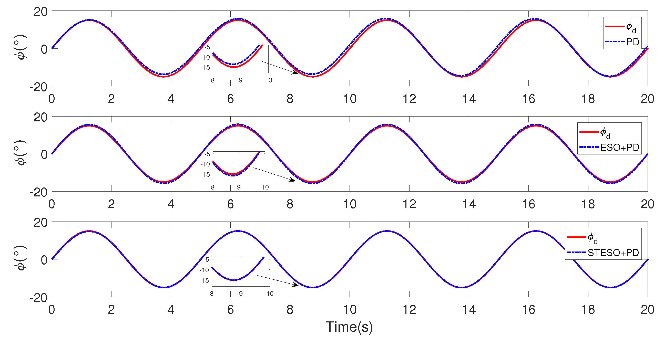
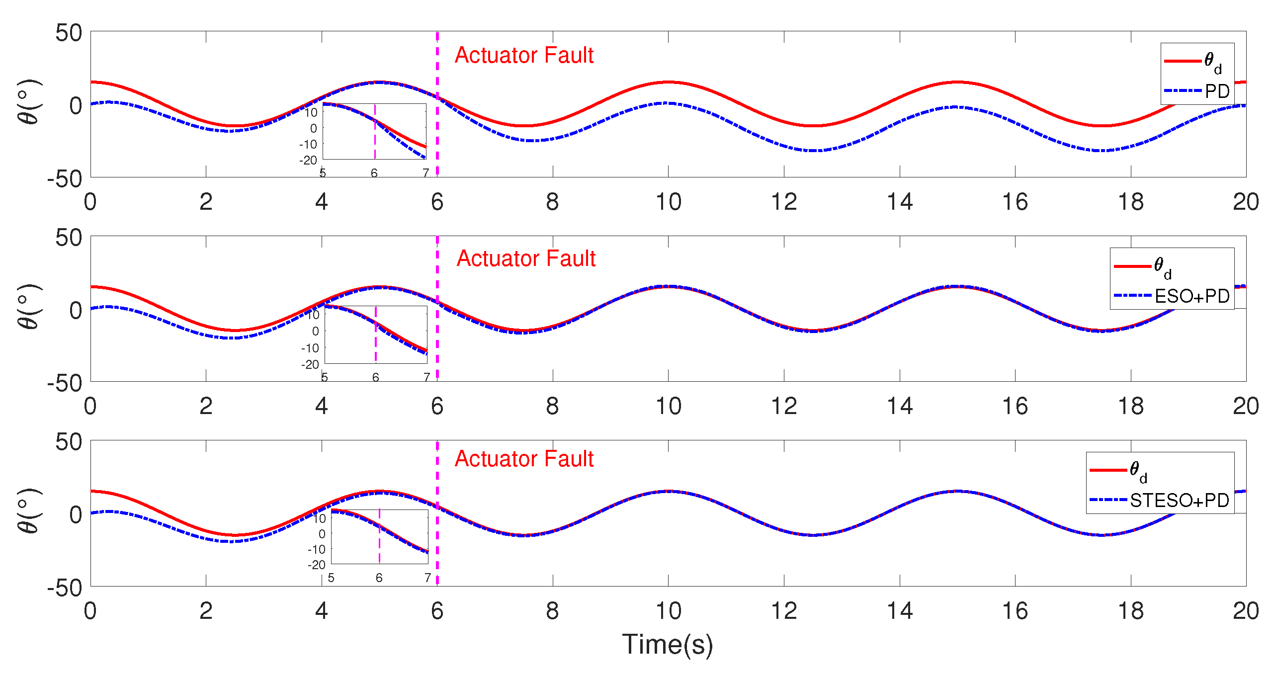
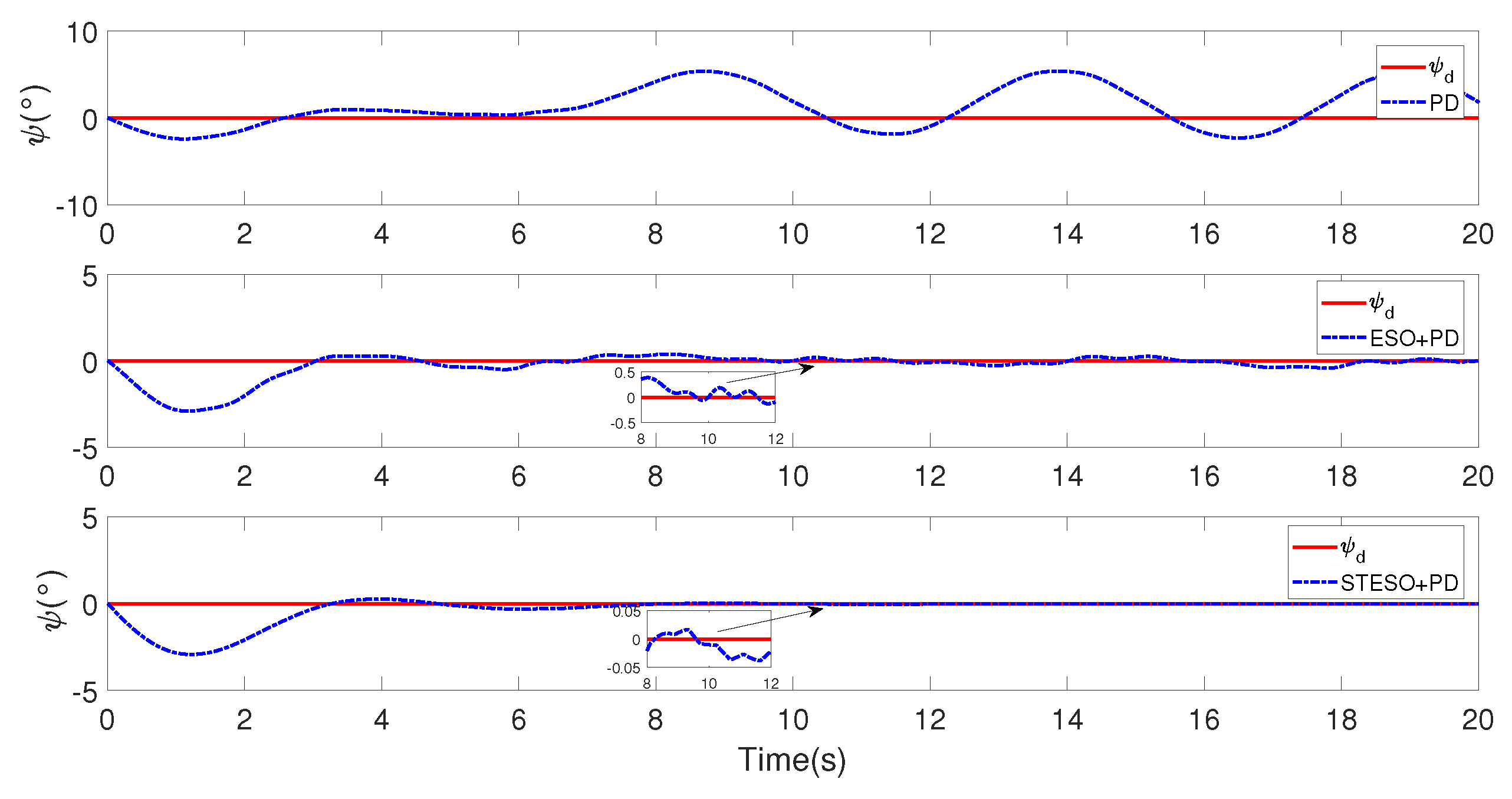
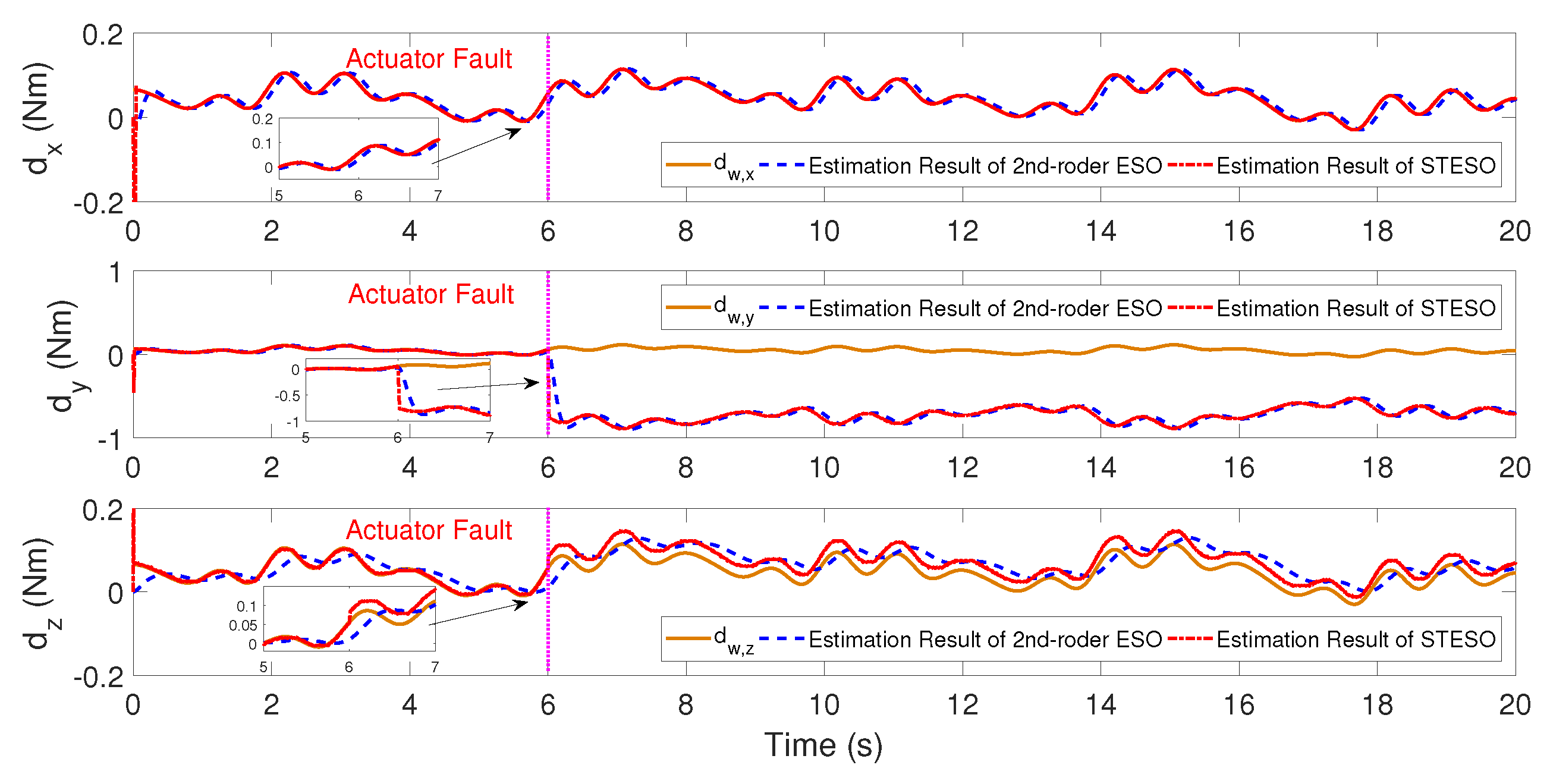
Figure 3, Figure 4 and Figure 5 show the comparison in attitude tracking results of nonlinear PD controller with STESO, 2nd-order ESO and without DUE. From those figures, we can see that the desired attitude commands can be tracked effectively by the controller with DUE. Moreover, the tracking errors are further reduced by introducing STESO as the DUE instead of 2nd-order ESO. Figure 6 shows the comparison in lumped disturbances estimation results of STESO and 2nd-order ESO. It is obvious that compared with STESO, some phase delay exist in the estimation results of the 2nd-order ESO, which leads to its estimation error convergences into a bounded area. Meanwhile, the estimation errors of STESO almost asymptotically convergence to zero. Especially when the disturbance torque suddenly changes, STESO has more advantages. In general, from the numerical simulation results, we can be conclude that STESO has a higher disturbance estimation accuracy, which in turn improves attitude control accuracy.
5.1.2. Case B. STSMC vs. Nonlinear PD
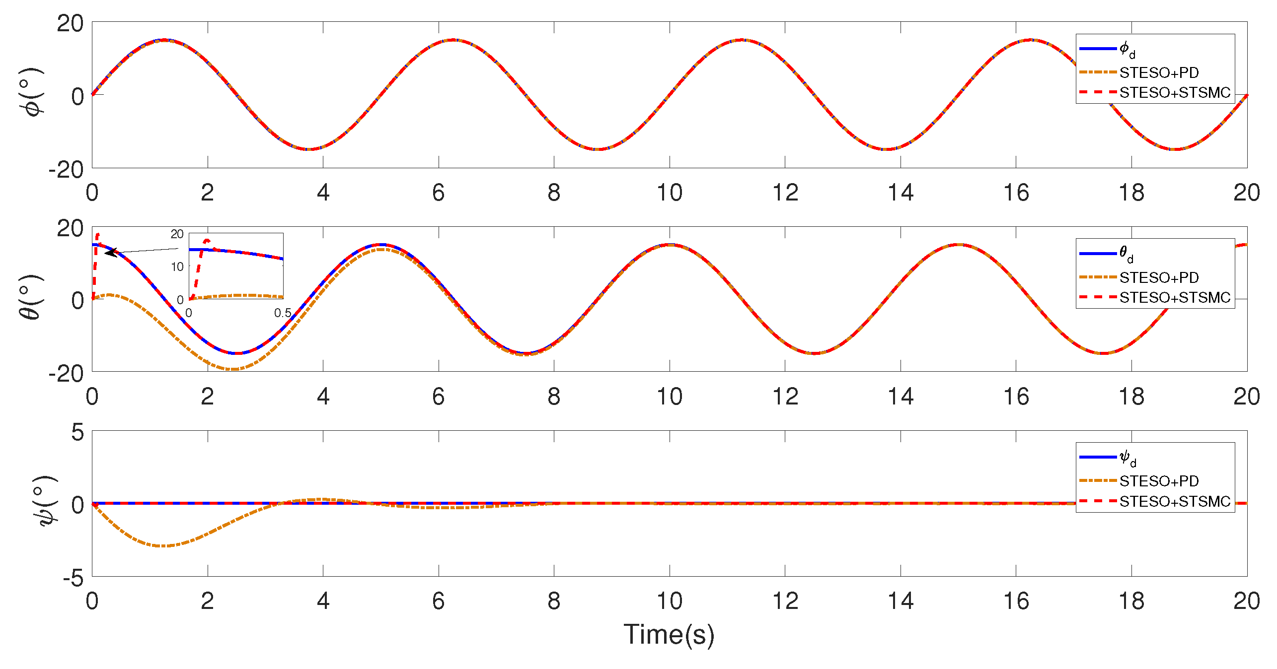
In order to verify the fast convergence of STSMC, two comparative simulations are performed with the same STESO of different controllers. The controller gains of STSMC are chosen as , , , the STESO and nonlinear PD parameters are the same with those provided in previous.
The comparison in attitude tracking results between STSMC and Nonlinear PD are illustrated in Figure 7. From this figure, we can see that quickly convergence of the attitude of quadrotor can be achieved by using STSMC as the FC. And by introducing ST algorithm into SMC, the chattering is reduced.
5.2. Experimental Results
In order to evaluate the effectiveness of the developed algorithm in practical applications, we have also tested the proposed control scheme on a selfassembled GF360 quadrotor, where an open-source flight controller PIXHAWK [46,47] was used as the autopilot of the quadrotor.
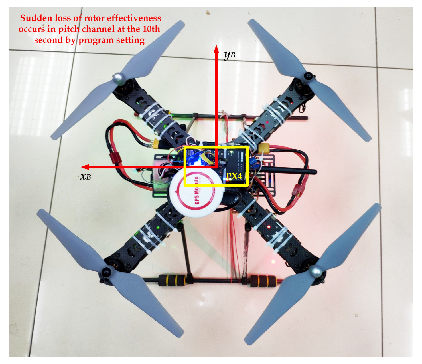
5.2.1. Case A: STESO vs. 2nd-Order ESO
In this case, quadrotor is freely flying and we mainly aim to achieve the fast stabilization of quadrotor attitude on condition that actuator faults occur. According to the simulation results, we can conclude that STESO algorithm has advantage in quick response to the lumped disturbances. And in order to verify its effectiveness in actual flight, three comparative real time experiments are conducted to handle the sudden lose of rotor effectiveness. The experimental setup is shown in Figure 8, and freely flying is performed. As it is dangerous to damage the propeller during flight, we use software to set up a sudden lose of rotor effectiveness in pitch channel at the 10th second. We choose the traditional nonlinear PD controller as the FC in these experiments, where the performances of the PD controller with STESO, 2nd-order ESO or without DUE are compared. The gains of the PD controller are chosen as and , the gains of the STESO are and , the bandwidth of the 2nd-order ESO is 4 rad/s, i.e., the observer gains are .
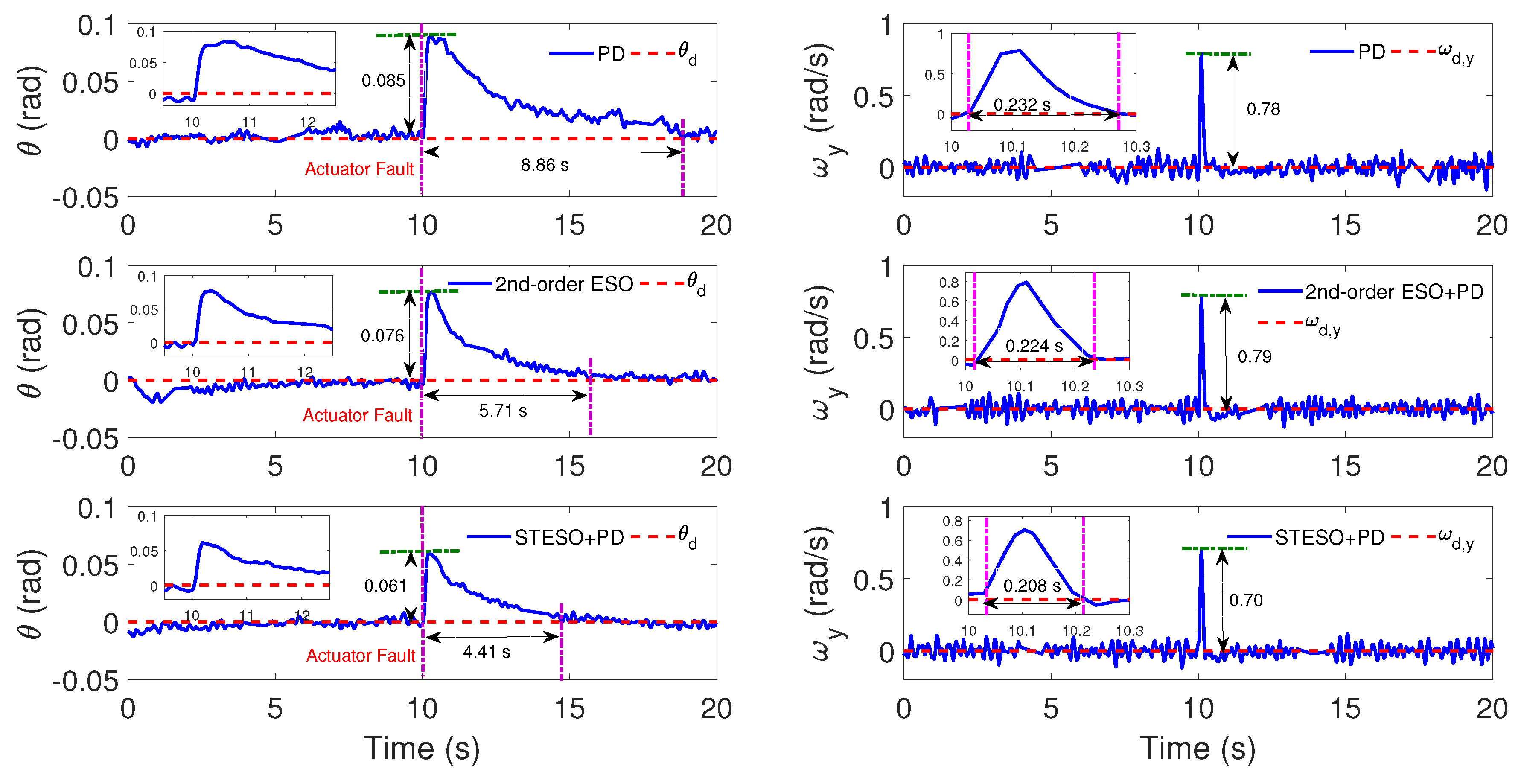
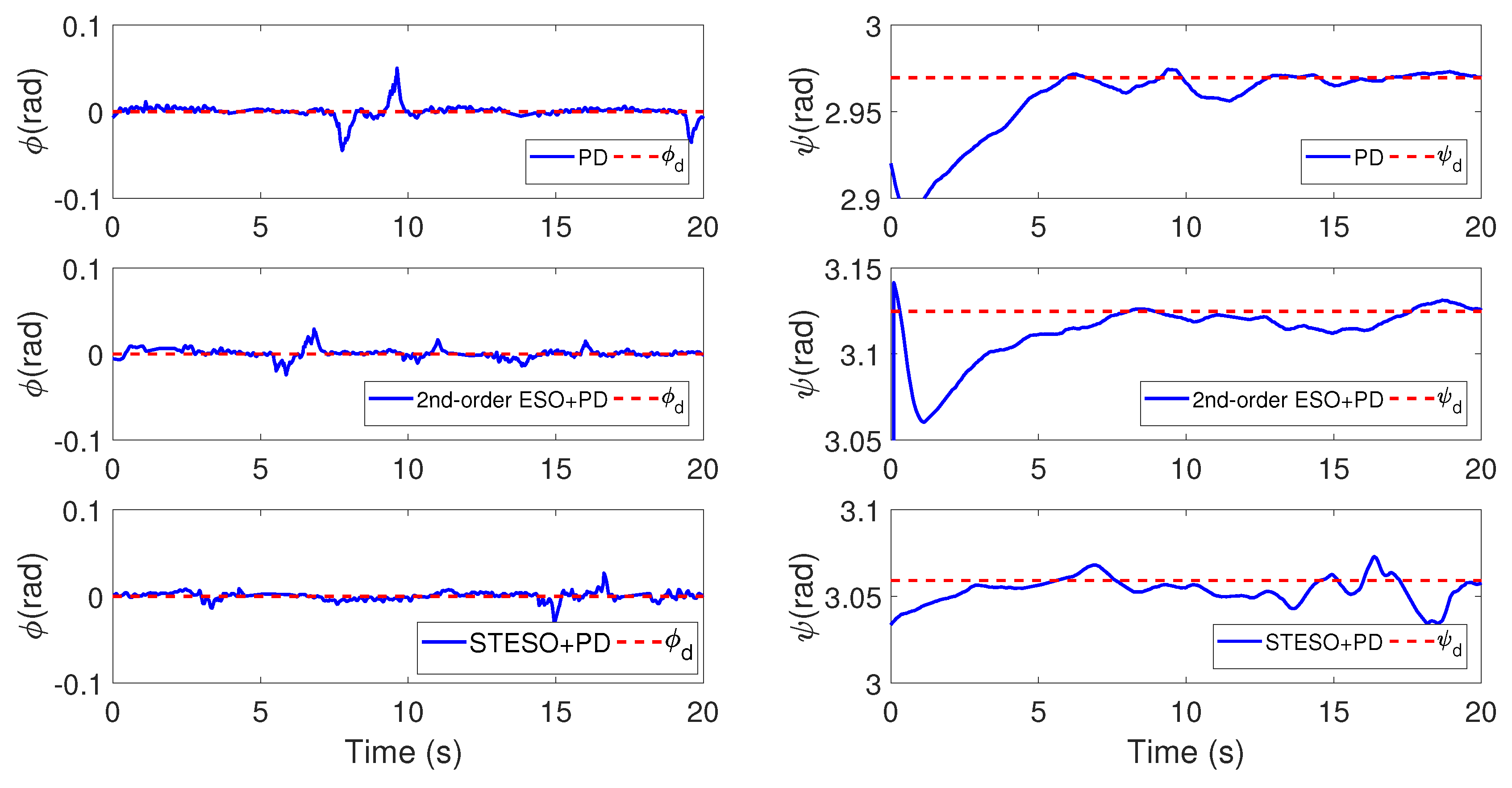
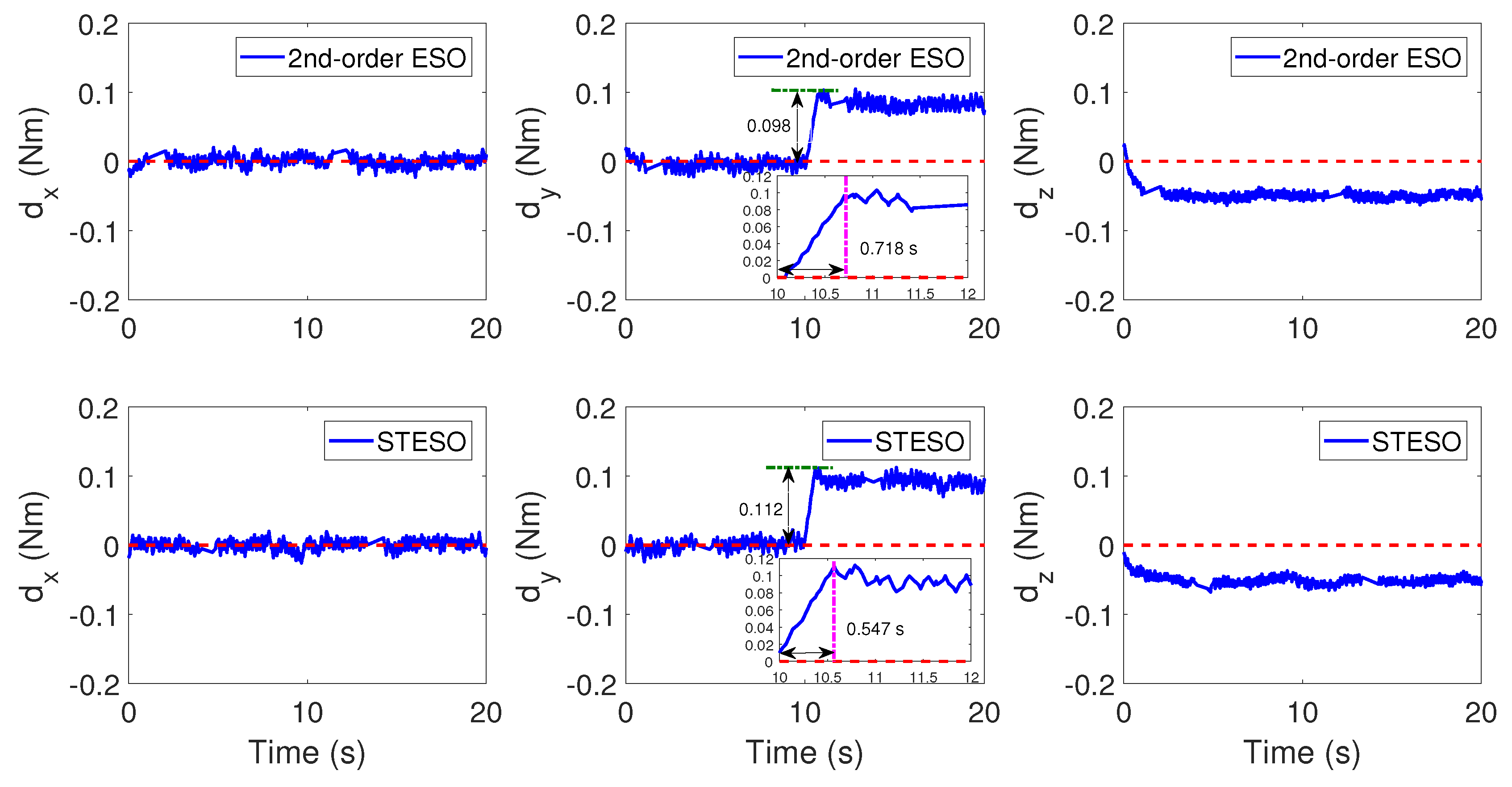
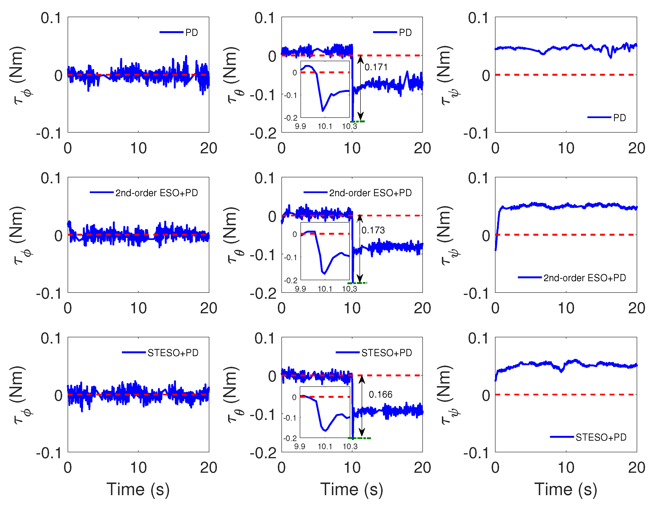
The experiment curves of the attitude are plotted in Figure 9 and Figure 10. From Figure 9, we can see that when the same loss of rotor effectiveness occurs, the deflections of pitch angle and angular rate in PD controller with STESO method are the smallest and the recovery times are the shortest. Figure 11 show the disturbances estimate curves of proposed STESO and 2nd-order ESO respectively. It can be seen that the convergence time of STESO is shorter that 2nd-order ESO. In general, the comparison of the experiment results are list detailly in Table 2. Furthermore, the corresponding control torques are shown in Figure 12.
5.2.2. Case B: Proposed Method vs. Nonlinear PD
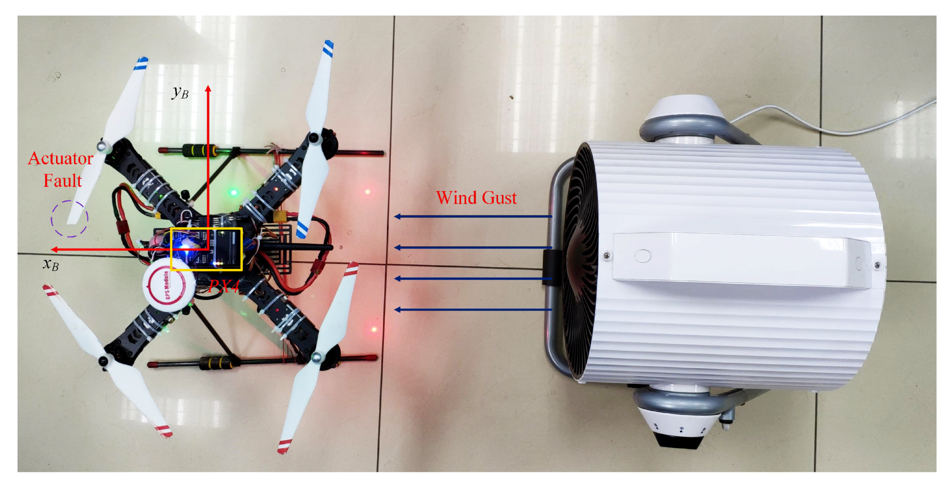
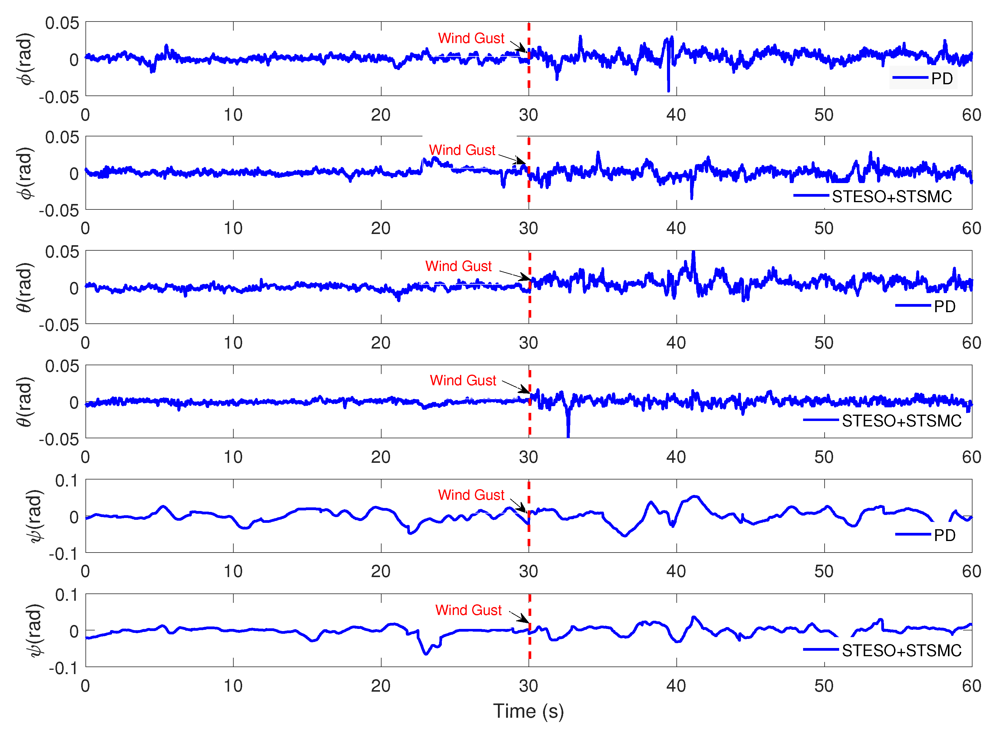
The main propose in this case is to show the performance of the developed method for quadrotor subject to lumped disturbances such as wind disturbance and actuator fault. As shown in Figure 13, We install a damaged propeller on the to perform the fault of the actuator, and then keep the quadrotor hovering in wind gust by remote control. In order to ensure the same experimental conditions, our experiments is run in a controlled indoor environment. We use an electrical fan with adjustable wind speed to generate the disurbance torque acting on the pitch channel of quadrotor. The average wind speed is around 4.5 m/s and turn on the electric fan at the 30 s. The experiments are carried out in our lab without GPS signals.
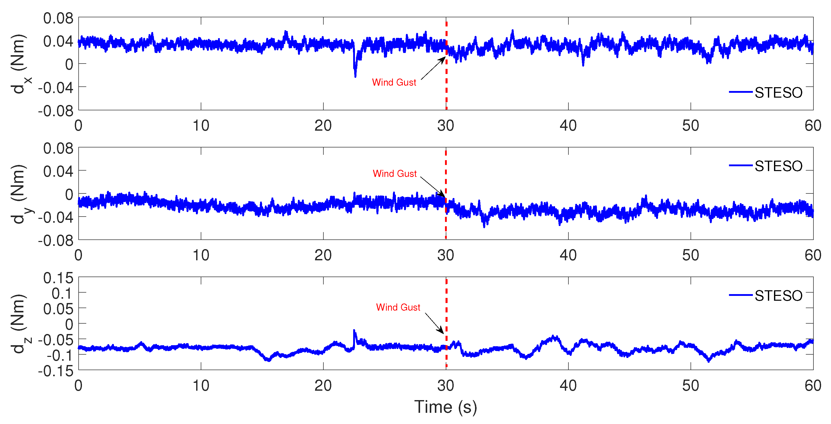
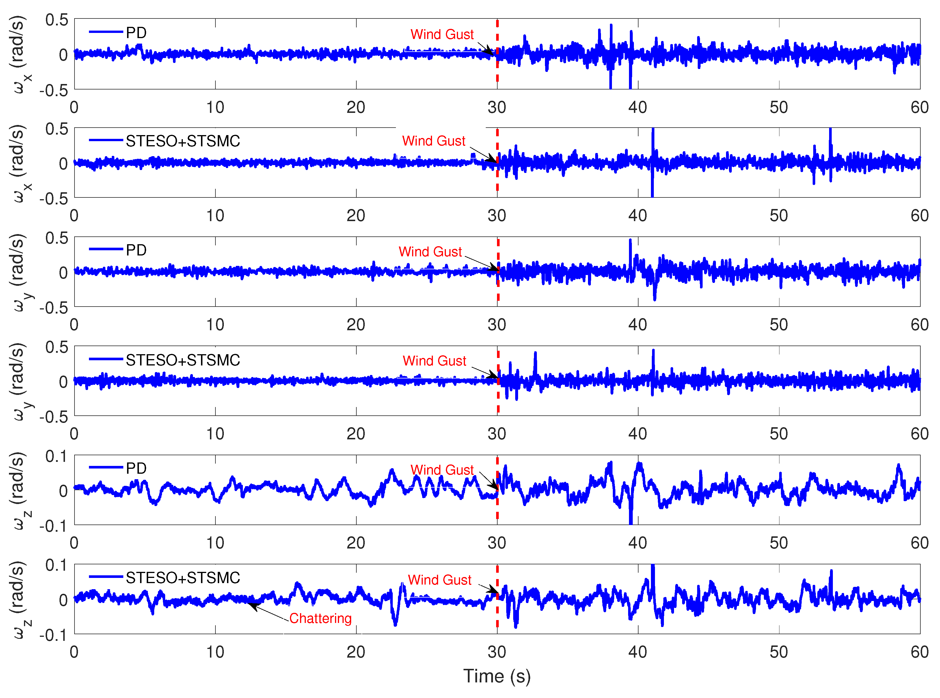
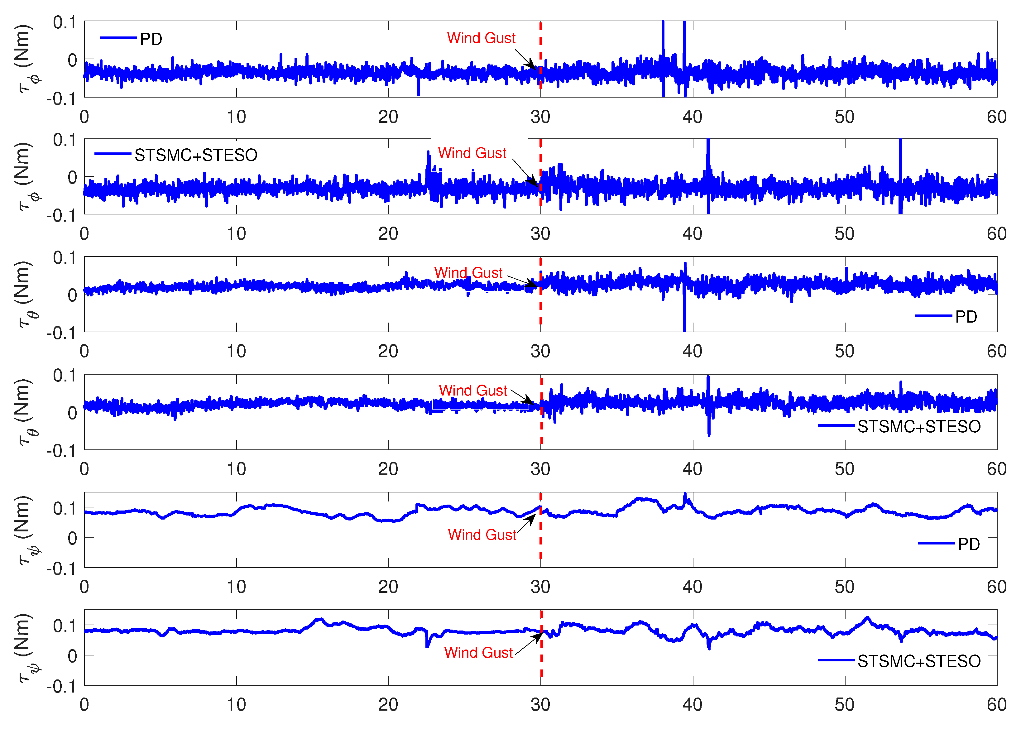
Figure 14 shows the estimation results of the STESO. From this figure, we can see that the actuator fault in leads to a steady disturbance torque acting on the quadrotor in hovering flight, i.e., Nm, Nm and Nm. The wind gust mainly leads to the stochastic disturbance torque in each channel, plus a steady torque about −0.01 Nm in pitch channel. The attitude control results in this case are shown in Figure 15 and Figure 16. It can be observed that the control performance is improved by introducing the proposed method compared with the nonlinear PD controller. In addition, the root mean square (RMS) errors of the attitude angles obtained by the proposed controller and PD controller are list in Table 3. And Figure 17 illustrates the control inputs in each channel.
6. Conclusions
In this paper, the problem of high precision attitude tracking for quadrotor in the presence of wind gust and actuator fault is investigated. In order to estimate and attenuate the disturbances timely and accurately, a STESO is proposed and successfully implemented as the DUE in experiments. Also, a STSMC is designed as the FC to drive the attitude angle and angular velocity to their desired value in finite time. From the comparative simulation and experiment results, we can conclude that when the parameter selection rule given in this article of is satisfied, the proposed super-twisting algorithm based controller can relize the fast converge to the desired attitude precisely with less chattering. And compared with the traditional Higher-order ESO, STESO has a higher disturbance estimation accuracy, which in turn improves attitude control accuracy.
References
Supplementary Materials
The Simulinlk simulation algorithm is available online at https://pan.baidu.com/s/1I-OVIDoOKMJhaNP-KbFjsA, password: 1l3i.
Author Contributions
Conceive and design the algorithm, Z.W. and D.S.; Perform the experiments, D.S.; Software, D.S.; Project administration, Z.W. and W.C.; Supervision, Z.W.
Funding
This work was funded by the State Key Development Program for Basic Research of China (Grant No. 2013CB035503).
Conflicts of Interest
The authors declare no conflicts of interest.
References
- Stepaniak, M.J.; van Graas, F.; de Haag, M.U. Design of an Electric Propulsion System for a Quadrotor Unmanned Aerial Vehicle. J. Aircr. 2009, 46, 1050–1058. [Google Scholar] [CrossRef]
- Gupte, S.; Mohandas, P.I.T.; Conrad, J.M. A Survey of Quadrotor Unmanned Aerial Vehicles. In Proceedings of the IEEE Southeastcon, Orlando, FL, USA, 15–18 March 2012. [Google Scholar]
- Ozbek, N.S.; Onkol, M.; Efe, M.O. Feedback control strategies for quadrotor-type aerial robots: A survey. Trans. Inst. Meas. Control 2016, 38, 529–554. [Google Scholar] [CrossRef]
- Bouabdallah, S.; Becker, M.; Siegwart, R. Autonomous miniature flying robots: Coming soon! IEEE Robot Autom Mag. 2007, 14, 88–98. [Google Scholar] [CrossRef]
- Han, W.X.; Wang, Z.H.; Shen, Y. Fault estimation for a quadrotor unmanned aerial vehicle by integrating the parity space approach with recursive least squares. Proc. Inst. Mech. Eng. Part G J. Aerosp. Eng. 2018, 232, 783–796. [Google Scholar] [CrossRef]
- Tian, B.L.; Ma, Y.X.; Zong, Q. A Continuous Finite-Time Output Feedback Control Scheme and Its Application in Quadrotor UAVs. IEEE Access 2018, 6, 19807–19813. [Google Scholar] [CrossRef]
- Huang, M.; Xian, B.; Diao, C.; Yang, K.Y.; Feng, Y. Adaptive Tracking Control of Underactuated Quadrotor Unmanned Aerial Vehicles via Backstepping. In Proceedings of the 2010 American Control Conference, Baltimore, MD, USA, 30 June–2 July 2010; pp. 2076–2081. [Google Scholar]
- Salih, A.L.; Moghavvemi, M.; Mohamed, H.A.F.; Gaeid, K.S. Flight PID controller design for a UAV quadrotor. Sci. Res. Essays 2010, 5, 3660–3667. [Google Scholar]
- Lee, K.U.; Kim, H.S.; Park, J.B.; Choi, Y.H. Hovering Control of a Quadrotor. In Proceedings of the 2012 12th International Conference on Control, Automation and Systems (Iccas), JeJu Island, Korea, 17–21 October 2012; pp. 162–167. [Google Scholar]
- González-Vázquez, S.; Moreno-Valenzuela, J. A New Nonlinear PI/PID Controller for Quadrotor Posture Regulation. In Proceedings of the 2010 IEEE Electronics, Robotics and Automotive Mechanics Conference, Morelos, Mexico, 28 September–1 October 2010; pp. 642–647. [Google Scholar]
- González-Vázquez, S.; Moreno-Valenzuela, J. Motion Control of a Quadrotor Aircraft via Singular Perturbations. Int. J. Adv. Robot. Syst. 2013, 10, 368. [Google Scholar] [CrossRef] [Green Version]
- Liu, H.; Lu, G.; Zhong, Y.S. Robust LQR Attitude Control of a 3-DOF Laboratory Helicopter for Aggressive Maneuvers. IEEE Trans. Ind. Electron. 2013, 60, 4627–4636. [Google Scholar] [CrossRef]
- Munoz, F.; Gonzalez-Hernandez, I.; Salazar, S.; Espinoza, E.S.; Lozano, R. Second order sliding mode controllers for altitude control of a quadrotor UAS: Real-time implementation in outdoor environments. Neurocomputing 2017, 233, 61–71. [Google Scholar] [CrossRef]
- Avram, R.C.; Zhang, X.D.; Muse, J. Nonlinear Adaptive Fault-Tolerant Quadrotor Altitude and Attitude Tracking With Multiple Actuator Faults. IEEE Trans. Control Syst. Technol. 2018, 26, 701–707. [Google Scholar] [CrossRef]
- Wang, C.; Song, B.F.; Huang, P.F.; Tang, C.H. Trajectory Tracking Control for Quadrotor Robot Subject to Payload Variation and Wind Gust Disturbance. J. Intell. Robot. Syst. 2016, 83, 315–333. [Google Scholar] [CrossRef]
- Basri, M.A.M.; Husain, A.R.; Danapalasingam, K.A. Stabilization and trajectory tracking control for underactuated quadrotor helicopter subject to wind-gust disturbance. Sadhana Acad. Proc. Eng. Sci. 2015, 40, 1531–1553. [Google Scholar] [CrossRef]
- Chen, W.H.; Ohnishi, K.; Guo, L. Advances in Disturbance/Uncertainty Estimation and Attenuation. IEEE Trans. Ind. Electron. 2015, 62, 5758–5762. [Google Scholar] [CrossRef]
- Yang, J.; Chen, W.H.; Li, S.H.; Guo, L.; Yan, Y.D. Disturbance/Uncertainty Estimation and Attenuation Techniques in PMSM Drives-A Survey. IEEE Trans. Ind. Electron. 2017, 64, 3273–3285. [Google Scholar] [CrossRef]
- Wang, Z.; Wu, Z. Nonlinear attitude control scheme with disturbance observer for flexible spacecrafts. Nonlinear Dyn. 2015, 81, 257–264. [Google Scholar] [CrossRef]
- Wang, Z.; Wu, Z.; Du, Y.J. Adaptive sliding mode backstepping control for entry reusable launch vehicles based on nonlinear disturbance observer. Proc. Inst. Mech. Eng. Part G J. Aerosp. Eng. 2016, 230, 19–29. [Google Scholar] [CrossRef]
- Pu, Z.Q.; Yuan, R.Y.; Yi, J.Q.; Tan, X.M. A Class of Adaptive Extended State Observers for Nonlinear Disturbed Systems. IEEE Trans. Ind. Electron. 2015, 62, 5858–5869. [Google Scholar] [CrossRef]
- Wang, H.D.; Huang, Y.B.; Xu, C. ADRC Methodology for a Quadrotor UAV Transporting Hanged Payload. In Proceedings of the 2016 IEEE International Conference on Information and Automation (ICIA), Ningbo, China, 1–3 August 2016; pp. 1641–1646. [Google Scholar]
- Xia, Y.Q.; Pu, F.; Li, S.F.; Gao, Y. Lateral Path Tracking Control of Autonomous Land Vehicle Based on ADRC and Differential Flatness. IEEE Trans. Ind. Electron. 2016, 63, 3091–3099. [Google Scholar] [CrossRef]
- Dou, J.X.; Kong, X.X.; Wen, B.C. Altitude and attitude active disturbance rejection controller design of a quadrotor unmanned aerial vehicle. Proc. Inst. Mech. Eng. Part G J. Aerosp. Eng. 2017, 231, 1732–1745. [Google Scholar] [CrossRef]
- Busawon, K.K.; Kabore, P. Disturbance attenuation using proportional integral observers. Int. J. Control 2001, 74, 618–627. [Google Scholar] [CrossRef]
- Gao, Z.W.; Breikin, T.; Nang, H. Discrete-time proportional and integral observer and observer-based controller for systems with both unknown input and output disturbances. Opt. Control Appl. Meth. 2008, 29, 171–189. [Google Scholar] [CrossRef]
- Alcan, G.; Unel, M. Robust Hovering Control of a Quadrotor Using Acceleration Feedback. In Proceedings of the 2017 International Conference on Unmanned Aircraft Systems (Icuas’17), Miami, FL, USA, 13–16 June 2017; pp. 1455–1462. [Google Scholar]
- Han, J.Q. From PID to Active Disturbance Rejection Control. IEEE Trans. Ind. Electron. 2009, 56, 900–906. [Google Scholar] [CrossRef]
- Wang, W.; Gao, Z. A comparison study of advanced state observer design techniques. In Proceedings of the American Control Conference, Denver, CO, USA, 4–6 June 2003; Volume 6, pp. 4754–4759. [Google Scholar]
- Madonski, R.; Herman, P. Survey on methods of increasing the efficiency of extended state disturbance observers. ISA Trans. 2015, 56, 18–27. [Google Scholar] [CrossRef] [PubMed]
- Godbole, A.A.; Kolhe, J.P.; Talole, S.E. Performance Analysis of Generalized Extended State Observer in Tackling Sinusoidal Disturbances. IEEE Trans. Control Syst. Technol. 2013, 21, 2212–2223. [Google Scholar] [CrossRef]
- Madani, T.; Benallegue, A. Sliding mode observer and backstepping control for a quadrotor unmanned aerial vehicles. In Proceedings of the 2007 American Control Conference, New York, NY, USA, 9–13 July 2007; Volume 1–13, pp. 2462–2467. [Google Scholar]
- Chuei, R.; Cao, Z.W.; Man, Z.H. Super Twisting Observer based Repetitive Control for Aperiodic Disturbance Rejection in a Brushless DC Servo Motor. Int. J. Control Autom. Syst. 2017, 15, 2063–2071. [Google Scholar] [CrossRef]
- Utkin, V. On Convergence Time and Disturbance Rejection of Super-Twisting Control. IEEE Trans. Autom. Control 2013, 58, 2013–2017. [Google Scholar] [CrossRef]
- Li, P.; Ma, J.J.; Zheng, Z.Q. Disturbance-observer-based fixed-time second-order sliding mode control of an air-breathing hypersonic vehicle with actuator faults. Proc. Inst. Mech. Eng. Part G J. Aerosp. Eng. 2018, 232, 344–361. [Google Scholar] [CrossRef]
- Tian, B.L.; Liu, L.H.; Lu, H.C.; Zuo, Z.Y.; Zong, Q.; Zhang, Y.P. Multivariable Finite Time Attitude Control for Quadrotor UAV: Theory and Experimentation. IEEE Trans. Ind. Electron. 2018, 65, 2567–2577. [Google Scholar] [CrossRef]
- Chovancova, A.; Fico, T.; Hubinsky, P.; Duchon, F. Comparison of various quaternion-based control methods applied to quadrotor with disturbance observer and position estimator. Robot. Auton. Syst. 2016, 79, 87–98. [Google Scholar] [CrossRef]
- Bouabdallah, S.; Siegwart, R. Full control of a quadrotor. In Proceedings of the 2007 IEEE/RSJ International Conference on Intelligent Robots and Systems, San Diego, CA, USA, 29 October–2 November 2007; Volume 9, pp. 153–158. [Google Scholar]
- Waslander, S.; Wang, C. Wind Disturbance Estimation and Rejection for Quadrotor Position Control. In Proceedings of the AIAA Infotech@Aerospace Conference and AIAA Unmanned...Unlimited Conference, Seattle, WA, USA, 6–9 April 2009. [Google Scholar]
- Chen, Y.M.; He, Y.L.; Zhou, M.F. Decentralized PID neural network control for a quadrotor helicopter subjected to wind disturbance. J. Cent. South Univ. 2015, 22, 168–179. [Google Scholar] [CrossRef]
- Önder, E.M. Battery power loss compensated fractional order sliding mode control of a quadrotor UAV. Asian J. Control 2012, 14, 413–425. [Google Scholar]
- Shtessel, Y.; Edwards, C.; Fridman, L.; Levant, A. Sliding Mode Control and Observation; Springer: New York, NY, USA, 2014. [Google Scholar]
- Quan, Q.; Dai, X. Flight Performance Evaluation of UAVs. Available online: http://flyeval.com/ (accessed on 20 April 2018).
- Shi, D.; Wu, Z.; Chou, W. Harmonic Extended State Observer Based Anti-Swing Attitude Control for Quadrotor with Slung Load. Electronics 2018, 7, 83. [Google Scholar] [CrossRef]
- Shi, D.; Wu, Z.; Chou, W. Generalized Extended State Observer Based High Precision Attitude Control of Quadrotor Vehicles Subject to Wind Disturbance. IEEE Access 2018, 6, 2169–3536. [Google Scholar] [CrossRef]
- Meier, L.; Tanskanen, P.; Heng, L.; Lee, G.H.; Fraundorfer, F.; Pollefeys, M. PIXHAWK: A micro aerial vehicle design for autonomous flight using onboard computer vision. Auton. Robot. 2012, 33, 21–39. [Google Scholar] [CrossRef]
- Meier, L.; Tanskanen, P.; Fraundorfer, F.; Pollefeys, M. The Pixhawk Open-Source Computer Vision Framework for Mavs. In Proceedings of the International Conference on Unmanned Aerial Vehicle in Geomatics (UAV-G), New York, NY, USA, 14–16 September 2011; Volume 38-1, pp. 13–18. [Google Scholar]
Figure 1.
Coordinate systems of the quadrotor.

Figure 2.
Block diagram of the proposed control scheme.

Figure 3.
Simulation curves of in Case A.

Figure 4.
Simulation curves of in Case A.

Figure 5.
Simulation curves of in Case A.

Figure 6.
Disturbance estimation results in Case A.

Figure 7.
Simulation curves of attitude angle: STSMC vs. nonlinear PD.

Figure 8.
Experimental setup of the quadrotor hovering with sudden lose of rotor effectiveness in Case A.
Figure 8.
Experimental setup of the quadrotor hovering with sudden lose of rotor effectiveness in Case A.

Figure 9.
Experimental curves of and with different DUE in Case A.

Figure 10.
Experimental curves of and with different DUE in Case A.

Figure 11.
Disturbance estimation results of different DUE with actuator faults in Case A.

Figure 12.
Control input during flight experiments in Case A.

Figure 13.
Experimental setup of the quadrotor hovering in the wind field in Case B.

Figure 14.
Disturbance estimation results of STESO in Case B.

Figure 15.
Experimental curves of attitude angle , , in Case B.

Figure 16.
Experimental curves of angular rates , , in Case B.

Figure 17.
Control input during flight experiments in Case B.


Table 1.
Quadrotor parameters used in simulation.
| Parameter | Description | Value |
|---|---|---|
| m | Mass | kg |
| Roll inertia | ||
| Pitch inertia | ||
| Yaw inertia | ||
| l | Motor moment arm | m |
| g | Gravity acceleration | |
| Aerodynamic coefficient | ||
| Drag coefficient | ||
| Maximum rotational speed | 8214 r/min | |
| Minimum rotational speed | 100 r/min |
Table 2.
Comparison of control performances with different observers.
| Deflection | Recovery Time | Convergence Time | |||
|---|---|---|---|---|---|
| Without Estimator | 0.085 rad | 0.78 rad/s | 8.86 s | 0.232 s | / |
| 2nd-order ESO + PD | 0.076 rad | 0.79 rad/s | 5.71 s | 0.224 s | 0.718 s |
| STESO + PD | 0.061 rad | 0.70 rad/s | 4.41 s | 0.208 s | 0.547 s |
Table 3.
Comparison of attitude control performance: RMS error (rad).
| Actuator Fault Only | Actuator Fault+Wind Gust | |||||
|---|---|---|---|---|---|---|
| nonlinear PD | 0.0082 | 0.0072 | 0.0187 | 0.0160 | 0.0202 | 0.0204 |
| STESO + STSMC | 0.0094 | 0.0052 | 0.0135 | 0.0136 | 0.0116 | 0.0132 |
© 2018 by the authors. Licensee MDPI, Basel, Switzerland. This article is an open access article distributed under the terms and conditions of the Creative Commons Attribution (CC BY) license (http://creativecommons.org/licenses/by/4.0/).
Share and Cite
MDPI and ACS Style
Shi, D.; Wu, Z.; Chou, W. Super-Twisting Extended State Observer and Sliding Mode Controller for Quadrotor UAV Attitude System in Presence of Wind Gust and Actuator Faults. Electronics 2018, 7, 128. https://doi.org/10.3390/electronics7080128
AMA Style
Shi D, Wu Z, Chou W. Super-Twisting Extended State Observer and Sliding Mode Controller for Quadrotor UAV Attitude System in Presence of Wind Gust and Actuator Faults. Electronics. 2018; 7(8):128. https://doi.org/10.3390/electronics7080128
Chicago/Turabian StyleShi, Di, Zhong Wu, and Wusheng Chou. 2018. "Super-Twisting Extended State Observer and Sliding Mode Controller for Quadrotor UAV Attitude System in Presence of Wind Gust and Actuator Faults" Electronics 7, no. 8: 128. https://doi.org/10.3390/electronics7080128
Note that from the first issue of 2016, this journal uses article numbers instead of page numbers. See further details here.