1. Introduction
Microgrids are small-scale isolated distribution systems which are currently receiving increased attention due to the widespread use of renewable energy resources, energy storage batteries, and the increment of electronics-based loads that use DC current. Therefore, DC microgrids avoid cumbersome DC–AC–DC generation [
1,
2,
3,
4]. However, the usage of DC microgrids at distribution scale is increasing with the collaboration of various renewable resources due to the higher penetration of electric vehicles [
5,
6,
7]. DC microgrids reduce the number of conversion units and also overcome the disadvantages of AC power, such as transformers inrush current, phase angle, frequency synchronization, reactive power, and power quality [
3,
8,
9]. Although DC microgrids are emerging and inverter-based AC microgrids are the recent focus of research, many traditional AC loads appear in the system as DC loads when fed through inverter drive systems [
8]. When studying the conventional control hierarchy for a legacy power system grid, a hierarchical control system is conventionally adopted for microgrids [
10,
11,
12]. Multi-level hierarchical control is a tertiary control, which is responsible for the coordination between distributed generated units and the economic dispatch of the units. Tertiary control adjusts the microgrid voltage for the scheduled exchange of power between the microgrid and the main grid. It adjusts the load sharing and maximum power-sharing, which increases the utilization of renewable energy, suppresses stress, and affects the aging of the microgrids [
13,
14,
15]. To adjust the voltage set point of the primary controller by the tertiary and secondary controller, a primary controller is implemented locally with the droop mechanism to converge the voltage of the converters [
12]. Tertiary and secondary control systems are implemented in a centralized mode in such a way that they are connected with high-speed communication networks. Communication networks used to exchange the reference values for the primary control, and any link failure of the network system may lead the affected unit to malfunction, overstressing other units, and potentially leading the system towards instability and failure [
13]. A future extension for link failure in the controllability adds more complexity to the central controller. Distributed control is as an alternative to centralized systems which provides more reliability, easy scalability, and a simpler network for communication [
16,
17]. Structurally, it is desired to extend the distributed control in secondary and primary control levels; this control provides voltage regulation and better load sharing for DC microgrids [
15].
Better load sharing is implemented using communication between converters that assign the loads according to their rated power, which equalizes the per-unit current of all nodes and reduces circulating current and overstressing of all sources [
18,
19]. Droop control is primarily adopted for load sharing by adding a virtual resistance to every converter. Despite the ease and simplicity in a droop control, it suffers from poor voltage regulation and current sharing. The main reason for this is the virtual impedance and output voltage mismatch between converters, which affects the real power flow between DC power systems [
20,
21,
22]. Improvement in systems requires a secondary control system that has better voltage regulation and load sharing, which is done over a communication network. Secondary control may be a centralized system exchanging values over a fully connected communication network through directly connected nodes of the microgrid [
15,
22]. A centralized secondary control measure voltage of the microgrid calculates the restoration value of voltage for the microgrid and feeds the same value to every converter. It assumes that the voltage of every converter is the same for all the nodes in a microgrid, which is not a feasible assumption for a DC microgrid [
19].
The conventional DC droop technique is used to linearly reduce the DC output voltage such that current increases, and it has limitations in line resistance in a droop control and DC bus voltage deviation increases. Droop control helps to achieve the independent operation of converters and improves current sharing [
13]. The cooperative control of DC microgrids creates a distributed secondary and primary control paradigm. Secondary control adjusts set-points for the overall system, and the primary control regulates individual units employing droop control law. The controller controls the transmission line impedance and communicates with other converters in the form of a sparse technique for current sharing [
14]. Using a distributed network, consensus protocol is implemented which eliminates the need for master–slave topology. Voltage regulation at a fixed point and current in per-unit are used in consensus to share the current between nodes. This involves tertiary, secondary, and primary controls. Tertiary controls the power dispatch, secondary sets the point for operation, and primary is a droop control. The controller does not require any prior knowledge of the number of converters, which makes it plug-and-play system [
12]. The droop method is widely used for current or load sharing by using the virtual impedance of each converter, which prevents power sources from becoming overstressed [
15]. A high droop coefficient improves the load sharing, which results in a cost for degrading voltage regulation. To achieve the required load sharing, the droop coefficient varies in the range of line impedance and line variation [
16]. The communication network spans all over the microgrid for centralized control which is embedded in each converter. Node-to-node communication links are required for all sources, and any link failure makes the microgrid operation unstable. The effect of line impedance is also taken into account for the connected graph [
20]. Despite improved accuracy because of the fully connected network system, any individual link failure affects the system performance. Appropriately, it is required that the average voltage over the microgrid is directed at the global voltage set point controlled by the tertiary control, which is called global voltage regulation [
21,
23]. The efficiency of DC microgrids varies because of the effect of communication delays generated between the nodes to exchange values. This can cause system instability and response to load sharing of nodes [
24,
25,
26]. In a bi-directional connectivity graph system, when a large amount of data is exchanged, errors in communication may occur that result in deterioration of the system performance [
27,
28]. Due to the intermittent nature of renewable energy resources, a fast control scheme is required [
26]. A new control scheme at the secondary level is proposed with minimum data exchange to overcome the mismatch in operating reference points to in turn reduce the stress and stabilize the system. The proposed control scheme can detect communication link failure and reliable operation of the system by varying the gain for correction terms. The proposed scheme does not require the tertiary-level control which is usually used in conventional consensus-based communication control.
This paper focuses on the improvement of the secondary-level control of DC microgrids. The main features of the proposed distributed cooperative control are as follows:
Analysis of two-way cooperation in nodes through a communication graph by making improvements in secondary control, which can detect communication link failure and stabilize the system accordingly.
Each converter has a level of intelligence, which uses the proposed scheme to get correction terms and adjust the system more accurately.
The proposed control system does not require prior knowledge of the nodes, which gives it plug-and-play capability.
A sparse communication network is spanned throughout the microgrid, through which converters can communicate with their neighbors, which is completely different from the centralized control approach.
This manuscript is organized as follows:
Section 2 is related to the detection of communication islanding and its impact on the system. An introduction to graph theory is presented in
Section 3.
Section 4 demonstrates the proposed distributed control.
Section 5 presents the case studies and simulation. Finally, the conclusions of the paper are drawn in
Section 6.
3. Review of Graph Theory
A DC microgrid (MG) system can be represented using graph theory in the form of a graph. The requirement for representing a DC MG using graph theory arises due to the increased number of nodes. So, irrespective of the communication method, the information transfer from one node to another can be expressed graphically. Graph theory is a well-established field of mathematics which helps to study different scenarios and cases in DC MG systems for the exchange of information flow [
27].
A distributed cooperative control can be represented graphically.
Figure 1 shows the physical and cyber layers of the DC microgrid. Nodes represent the active sources and edges show the communication links between the nodes. The cyber layer lays the network to achieve global consensus by exchanging information with neighbors, which is an improvement upon conventional consensus systems. By exchanging values with neighbors, every agent sets its reference values according to neighbors information [
28]. Thus, cooperative control offers a global consensus, provided with the help of the communication network. So, communication link failure affects the system stability in achieving convergence and generates stress on nodes [
12,
29].
A bi-directional communication network as in
Figure 1b can be represented using graph theory. Such a graph is usually represented mathematically as a set of nodes
connected through the edges
. This set consists of elements such as
and
. When an edge exists between nodes
, it is called adjacent and the system creates an adjacent matrix
, where
N is the number of active source nodes. Adjacency matrix
consists of the communication weights, where
, if
and
, otherwise.
is the coefficient of communication for transferring data from node
to node
. Here the adjacency matrix is considered with a time-invariant function.
denotes a set of all neighbors of point
; that is, if
, then
receives the information from
. The degree matrix consists of an in-degree matrix and an out-degree matrix. The in-degree matrix
is a diagonal matrix,
. Similarly, with the out-degree matrix
,
. A Laplacian matrix is defined as
, whose eigenvalues adjust the global values for the microgrid. The Laplacian matrix is assumed to be balanced if the in-degree and out-degree matrices of every node are the same (i.e.,
). Essentially, the in-degree matrices have a greater effect on the global dynamics of the node, which is influenced by its neighbors. In a practical system, if the graph is undirected (which means all the links are bi-directional), then the Laplacian matrix is balanced [
30,
31,
32].
4. Proposed Distributed Control
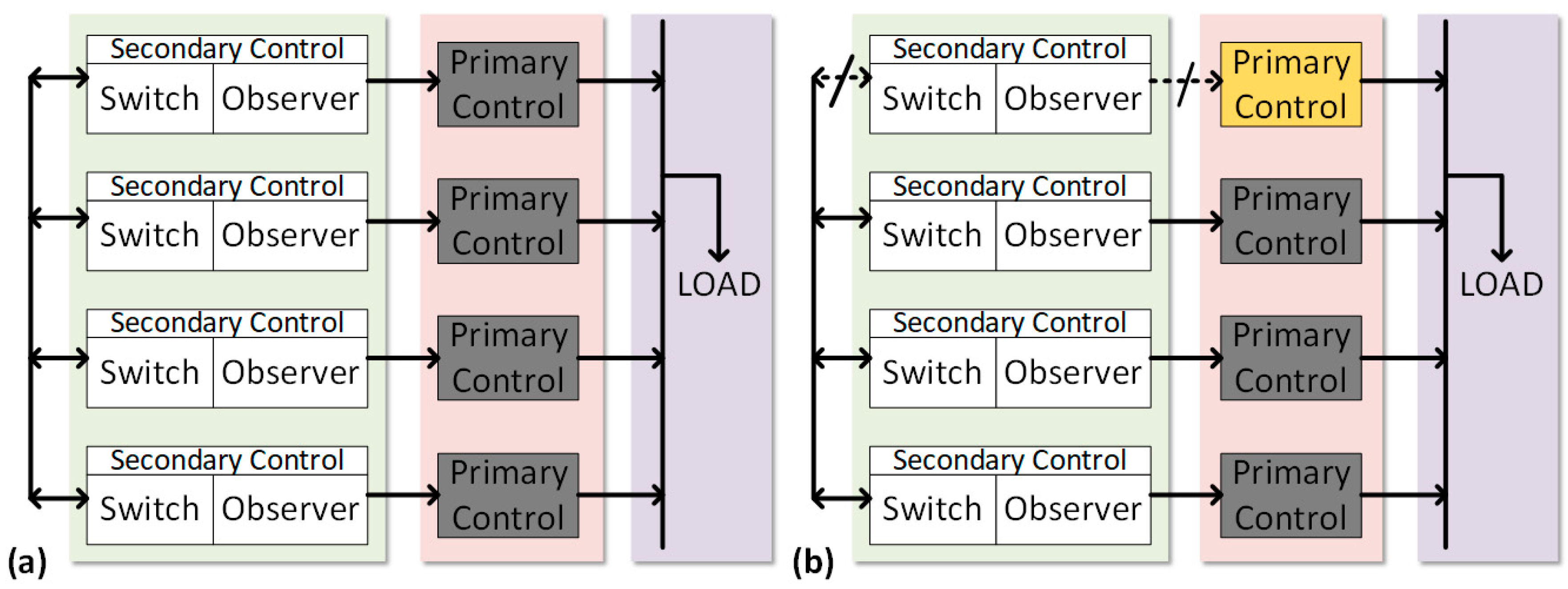
The global dynamics of voltage regulation and load sharing are the primary uses of the secondary control, which requires proper set points in order for every converter to operate. The proposed distributed control technique has the ability to detect link failure and stabilize the system during communication islanding. Communication link failure affects the system’s stability and functioning. The proposed control method is modified with a control switch that can detect the communication link failure, which can be on one side or on both sides and shifts the system to primary droop control. In primary control, the system works on droop and remains stable without using any tertiary-level control. The proposed scheme is shown in
Figure 3 and
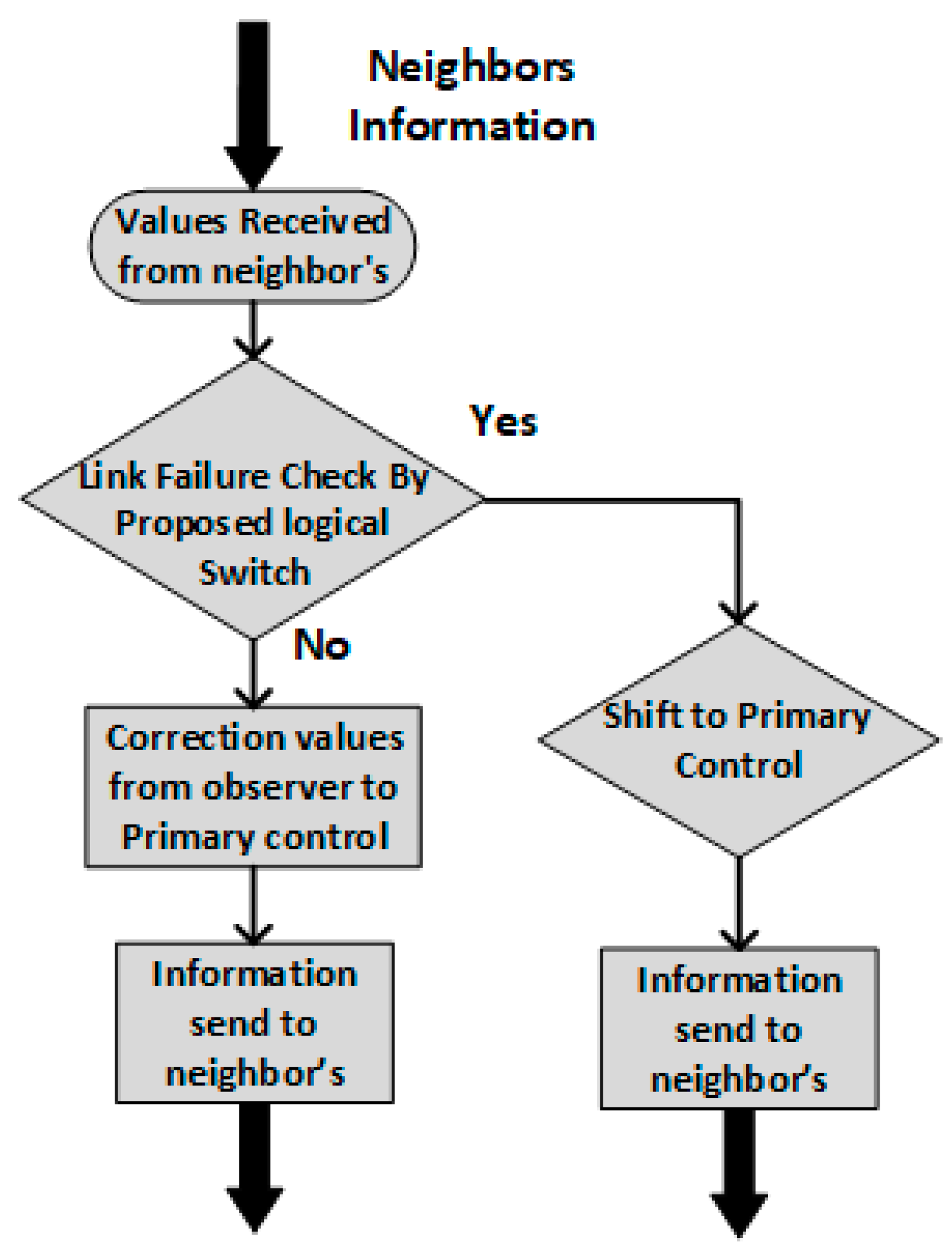
Figure 4, where a node receives reference points from neighbors and in the case of failure will stop secondary control and shift to primary control. A flowchart for the proposed control method is also shown in
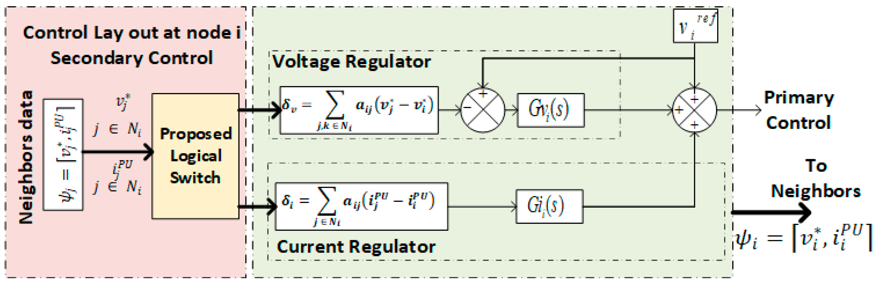
Figure 5, which explains the proposed control method better. When the information received from a neighbor’s system converges to a common reference point, it increases cooperation for load sharing and voltage reference points. Common reference points are consistently updated through a voltage regulator and a current regulator. Node reference voltage can be expressed as [
32]:
where
,
, and
are the global voltage parameters for constant reference voltages, voltage correction term of
th node, and current correction term for
th node, respectively. Reference points are further tuned in
Figure 3 using observers (Voltage and Current) on each node. In the case of any mismatch with the node’s reference point, correction terms are generated by the voltage observer
and the current observer
to converge the system for better load sharing and voltage regulation. The proposed controller has a logical switch with a voltage observer and a current observer. The proposed controller detects communication link failure, whereas the voltage observer on node
senses the voltage across the microgrid to compare voltage with the global reference
and converge the voltage of node
to clear any mismatch between nodes using the PI (Proportional Integral) controller
. A distributed cooperative observer estimates the voltage and current compared with the neighbor’s data for the average microgrid reference, as implemented in
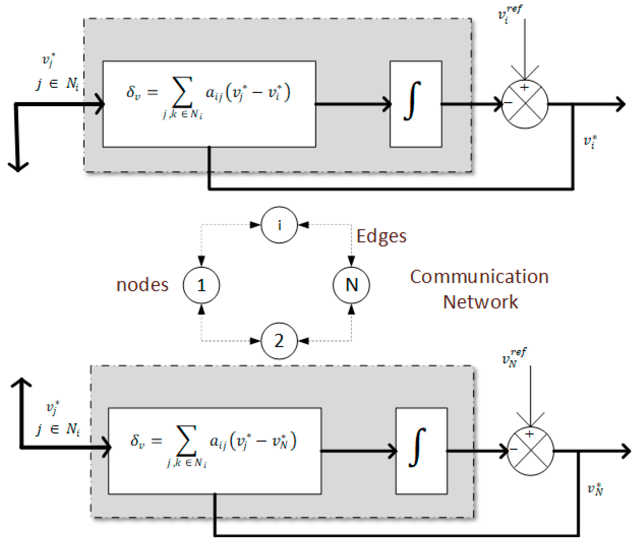
Figure 2. It uses the dynamic consensus framework to process the neighbors’ exchange data with local data and adjust the voltage regulation for the microgrid.
Figure 4 explains the main operation of the voltage observer to take global voltage averages. The voltage observer at node
receives the neighbor voltages
which can be written as [
13]:
Differentiating can be expressed as Equation (2):
Global observer dynamics can be arranged as:
The protocol which is used to update the set point for voltage in the voltage observer is referred to as dynamic consensus. As shown in Equation (4), the local set point (i.e.,
) is directly input into the estimation algorithm. Thus, any change in voltage at node
’s local set point quickly responds to the situation. As a result, the new
is set in the local system and also sent to the neighbors for the reference of other nodes [
33].
The vector for voltages
carries the measured voltage for each node. Similarly, the correction estimation vector is
and carries all the global voltage set points for all nodes. An equivalent equation for frequency can be expressed as:
A current regulator of node
checks the current reference value and tries to make a correction term to ensure equal load sharing between each node. Distributed line impedance varies the droop controller performance. As on node
, it compares local per-unit
current with the neighbors’ weighted average current per-unit and finds the correction value for current
[
13].
where
is the weight of the communication link,
is the current from neighbors, and
is the current of node
. Thus, if any mismatch between the per-unit current of the converters occurs, the current regulator will generate the correction term and adjust the current into a balanced form.
4.1. Single Converter model
DC MG systems based on multiple DC–DC converters usually have high switching frequency. Therefore, the impact of non-linearity in switching frequencies is averaged out, and owing to this fact the converters are a model based on state average modeling, and consensus control is also approximated as continuous in the time domain. However, when a connection failure occurs, the delay is very large in comparison to the normal delay in a communication network. The small signal model for a Buck converter is shown in (7) [
34,
35,
36]:
The transfer function for output values:
4.2. DC MG System Modeling
Let global reference voltage
and actual supplied current
vectors. The cooperative control of
Figure 3 generates terms
and
which are also represented as
at the primary control signal point [
13]. Accordingly,
and
are voltage and current correction term vectors. The Laplace transforms of
and
are
and
.
is the voltage controller matrix and
is the current controller matrix.
is the Laplace transform of
, which is the per-unit current vector
.
By, substituting (11) in (12),
The local voltage set point for proposed controller is
where
is the vector of the local voltage set and its Laplace transform is
.
r is the virtual resistance matrix. Substituting (10) and (13) in (14),
The dynamic behavior of the converter with a closed loop can be expressed as:
where
and
are the voltage and
is the gain of converter
. The global dynamics of the converter will be
where the transfer matrix is
. By substituting (15) in (17),
By rearranging (5), we can get
Let us suppose a delay function in the neighbor’s reference voltages. All of the delays are equal and periodic for delay value
.
For some sample of time, this function will be stable. The DC MG admittance matrix
is related to actual supplied current as
The detail of the distribution grid is contained in an admittance matrix. Therefore, (18) can be expressed as
Equation (22) describes the global dynamic with proposed controls, the system being linear. Suitable values for different gains can be found, such that poles of the system lie in the left half of the plan and the system will be stable for some open interval of delay
.
For periodic and synchronized communication, the value of
should be small enough such that system can achieve reasonable stability and robustness as targeted by the design specification. At the same time, it should be large enough such that it can be realized by practical means of implementation. It can safely be assumed that small variations in delay will not cause any system instability, as the bandwidth of secondary control, which depends on communication-based control, is quite a bit lower than communication rate. If the delay increases due to some uncertainty in the communication link, then the link can be considered as broken and reliance on such communication is not appropriate, as it can jeopardize system stability. A more generalized limit to this uncertain value of delay can be derived by discretizing the system and extending Lemma 1 of the agreement protocol in the presence of noise [
27]. This is expressed as follows: consider the discrete time equation for agreement protocol:
Equation (23) satisfies the following state:
Lemma 1. For a connected graph, the system’s trajectory (23) convergences to the agreement setw.p.1 (with probability 1) if the condition in (24) holds and for all.
For system convergence, a delay with fixed boundary according to Lemma 1, So the system will converge and remain stable under such boundary that the nodes consider stable and healthy. more than this delay boundary that node consider as failed in communication network.
5. Case Studies and Simulation
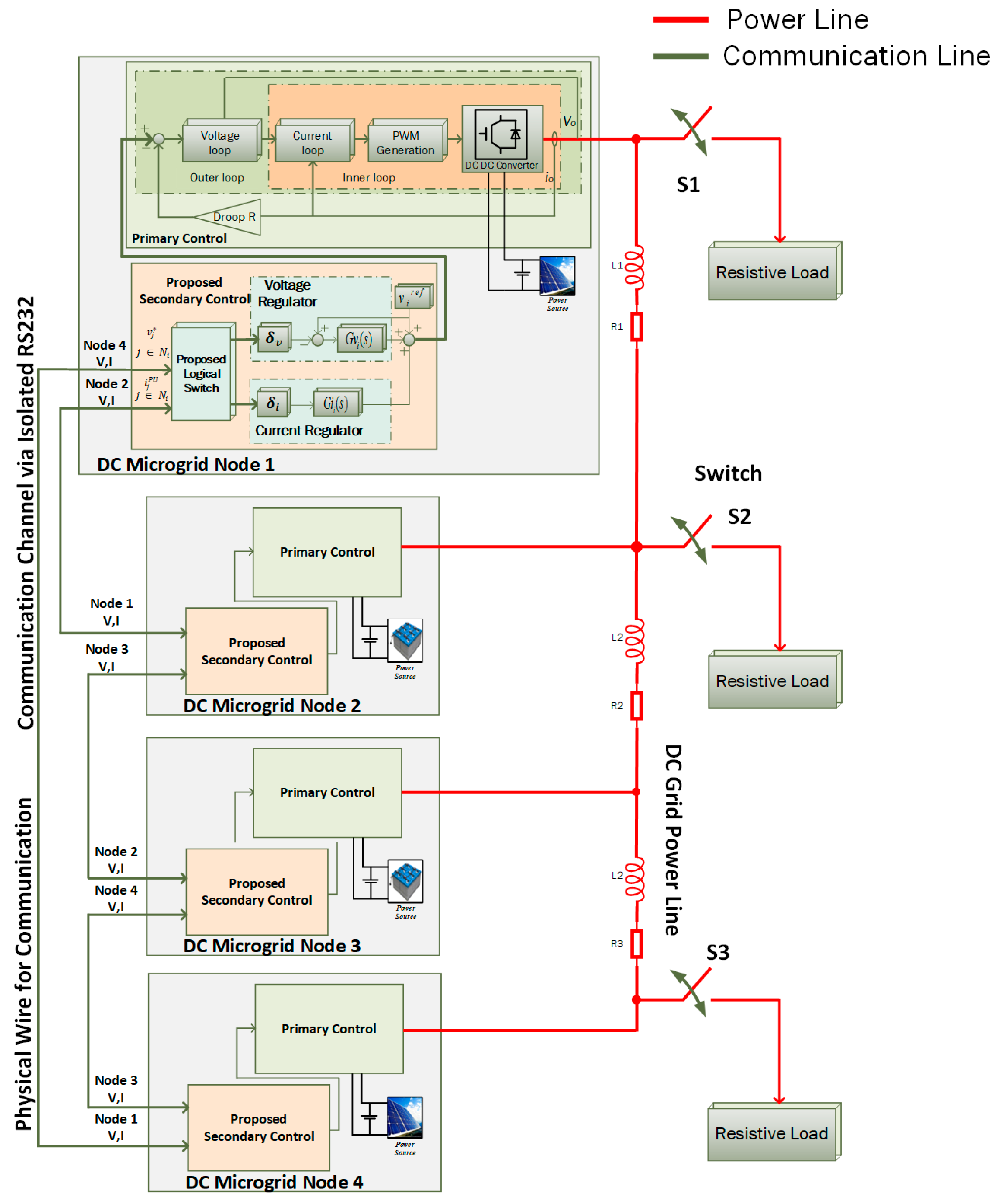
A circular bi-directional communication ring was considered for the DC MG experimental setup to check the effectiveness and performance of the proposed control method by performing simulations in MATLAB, as shown in
Figure 6. For the considered case study, the DC MG had a four-node radial network in a circular communication structure to support a DC resistive load connected on different nodes. For communication between nodes, an isolated RS232 was used in setup to exchange reference values. In the simulated case study, the effect of communication channel transmission delay was also considered. A detailed switch model was used for power converters to present more realistic results. The full case scenario is illustrated in
Figure 6, and detailed node parameters used for the experimental setup are given in
Table 1, which shows the communication links and power lines. The circular structure consisted of two-way communication with neighbors, as shown in
Figure 7. Transmission impedance effect was also considered in the experimental setup. As shown in
Figure 3 and
Figure 6, the proposed control scheme detects link failure between the connected nodes and adjusts the gains according to the link failure, as explained in the flowchart in
Figure 5. The detection algorithm is continuously working at every node, and if any link failure occurs, the secondary control quickly responds to the link failures and varies the gains that affect the voltage correction and current correction terms. Considering switch S2 in the experimental setup of the case study, only one node was connected with a load for the worst-case scenario with other nodes sharing the load. Consequently, the system output voltage and current sharing stabilized as shown in
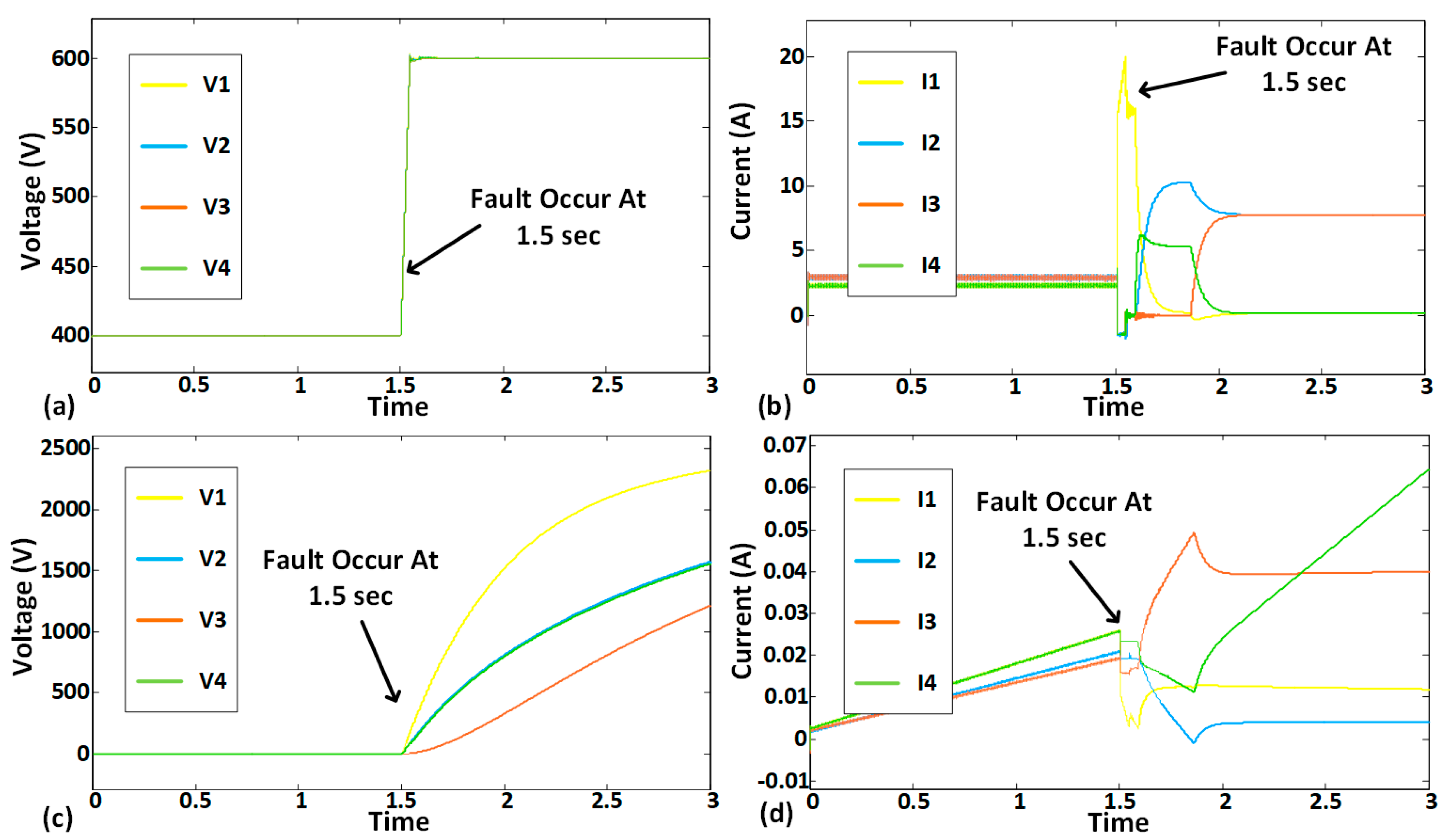
Figure 8a,b. The system remained stable, with variations in secondary control gain accordingly. Whenever link failure occurred in the MG as in
Figure 7c, the proposed controller at the secondary level detected the link failure and it varied the voltage gain and current correction, as can be seen in
Figure 8c,d. It can be seen from Equations (1) and (6) that for the correction term, the equation is dependent on the neighbor’s reference values. When a link failure occurs, the reference from the neighbors in the correction equations are constant or zero, which therefore leads to sharp variations in the system correction term as in
Figure 8c,d.
Figure 9a,b display a conventional system without a link failure detection system that generates a correction term in absence of reference values at the voltage and current correction. This will result in the output voltage following the input voltage due to correction terms as in
Figure 8c,d. The graphical representation is shown in
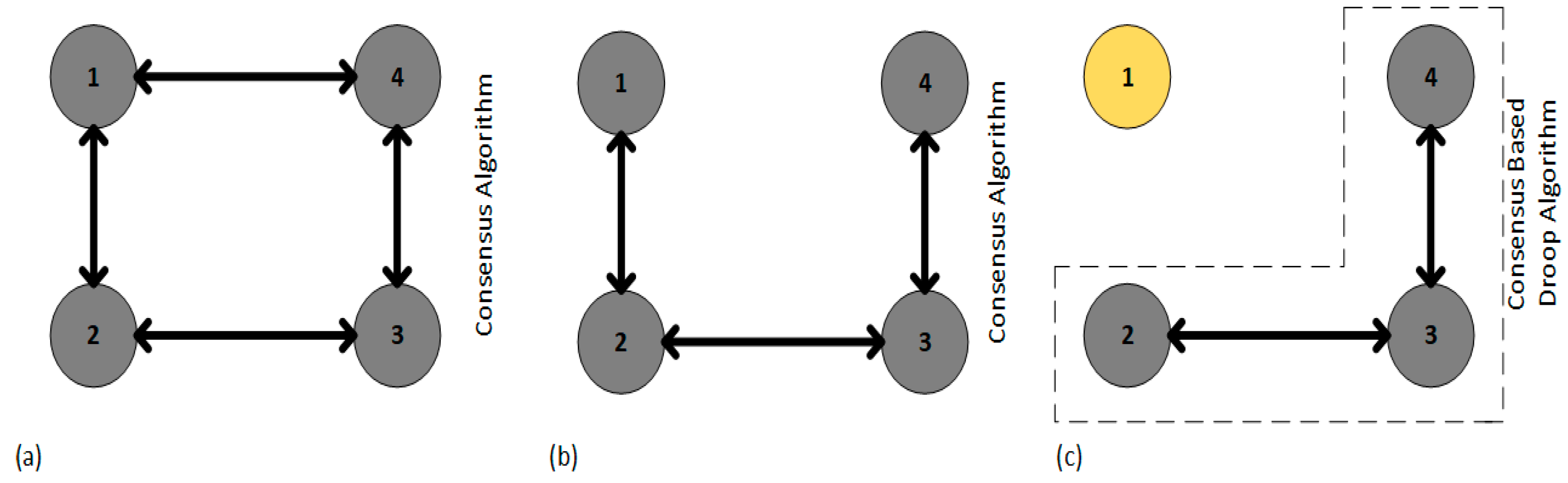
Figure 7 for different scenarios. Bi-directional system communication links are assumed to have a balanced Laplacian matrix and adjacency matrix for communication graph weights using
to generate correction terms.
Figure 7a shows the fully connected balanced Laplacian matrix as shown in Equation (25):
Similarly,
Figure 7b shows one communication link failure which changes the Laplacian matrix as shown in Equation (26). On the other hand, if failure of both links occurs, as shown in
Figure 7c, then its Laplacian for the remaining system will be as in Equation (27):
During regular connectivity, all four nodes will work normally and exchange values with neighbors for correction terms as shown in
Figure 6 and the first case of
Figure 7a. With that correction term, the system will converge to a common reference point and share the load in a balanced form. Whereas, if one link failure occurs in any two nodes as in
Figure 7b, the Laplacian will be different as in Equation (26), and consensus will work normally, in which it will vary the gain and adjust the system in order to maintain its stability and load sharing. As a result, the system has no effect on regular working of DC MG. If links fail on both sides then one node is communication islanding, whereas all other nodes can exchange information with each other. In that case, the proposed algorithm will maintain stability and load sharing by shifting the islanded node to droop by varying its gain. In contrast, the conventional secondary control would no longer be able to stabilize the system and requires tertiary control to take over the system for normal operation. The usage of the proposed control method helps in stabilizing the system performance and neutralizing the need for tertiary control in the system. By using a simulation study, comparisons were made between the conventional secondary control with the proposed control as shown in
Figure 8 and
Figure 9. Two cases were considered in the simulation: one is fully connected and the other is communication islanded, in which both links are assumed to be failed. Initially, the system worked in a fully connected condition, but link failure occurred at 1.5 s, and as in
Figure 8, the proposed algorithm maintained system stability and load sharing. In contrast, the regular consensus system became unstable, which affected system performance.
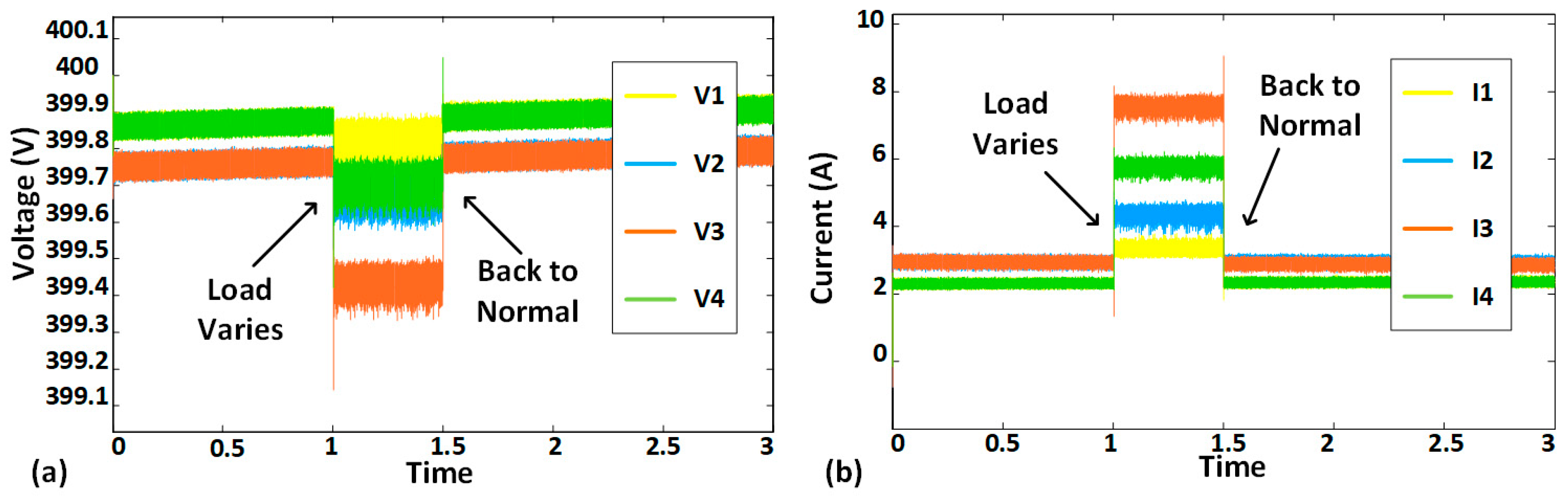
Plug-and-Play Capacity
The proposed system has plug-and-play capability. When one or more nodes’ communication links fail at any time, the proposed controls stabilize the system. Communication link failure makes communication islands of varied sizes in the system. The proposed controls work to balance the system in the case of communication islanding. The performance of the DC MG shown in
Figure 8 and
Figure 9 was satisfactory under such case. A load variation test was also done on the proposed control scheme, and it performed well and balanced the system in time, as in
Figure 10.

 ,
, 


