Abstract
Ice covering on overhead transmission lines would cause damage to transmission system and long-term power outage. Among various de-icing devices, a modular multilevel converter based direct-current (DC)de-icer (MMC-DDI) is recognized as a promising solution due to its excellent technical performance. Its principle feasibility has been well studied, but only a small amount of literature discusses its economy or hardware optimization. To fill this gap, this paper presents a quantitative analysis and calculation on the converter characteristics of MMC-DDI. It reveals that, for a given DC de-icing requirement, the converter rating varies greatly with its alternating-current (AC) -side voltage, and it sometimes far exceeds the melting power. To reduce converter rating and improve its economy, an optimized configuration is proposed in which a proper transformer should be configured on the input AC-side of converter under certain conditions. This configuration is verified in an MMC-DDI for a 500 kV transmission line as a case study. The result shows, in the case of outputting the same de-icing characteristics, the optimized converter is reduced from 151 MVA to 68 MVA, and the total cost of the MMC-DDI system is reduced by 48%. This conclusion is conducive to the design optimization of multilevel DC de-icer and then to its engineering application.
1. Introduction
Ice covering on overhead transmission lines is a serious threat to the safe operation of power grids. Overweight ice would break wires or collapse towers, and then cause disruption of power transmission and large-scale outage [1,2]. The ice storms in North America 1998 [3], Germany 2005 [4], and China 2008 [5] are good examples of such consequences. In order to protect the grid from ice disaster, dozens of anti-icing or de-icing methods have been proposed [1,3,5,6], such as thermal de-icing, mechanical de-icing, passive icephobic coatings, etc.
Among various de-icing methods, heating of ice-covered line conductors by electrical current is recognized as the most efficient engineering approach to minimize the catastrophic consequences of ice events [5,6,7,8] because it can eliminate the ice covered on hundreds of kilometers of line within an hour, without damaging the grid structure or polluting the environment. Both alternating-current (AC) and direct-current (DC) can be used to melt ice, but AC ice-melting is usually used for transmission lines up to 110 kV, while DC ice-melting is more recommended for high voltage lines up to 500 kV [3,4]. In a DC de-icing system, the most critical part is the DC de-icer (DDI), which generates the required DC voltage and current.
Nowadays, the most widely adopted de-icer is the thyristor-based line-commutated converter (LCC) [9,10,11], derived from the conventional high voltage direct current transmission (HVDC) technology. It can output a wide range of DC voltages by regulating the thyristor phase shift angle to meet the de-icing requirement of various lines; moreover, it can operate as a static var compensator (SVC) when there is no de-icing requirement. Thus, it has been widely used in Russia, Canada, China [5,12,13], etc. However, due to the inherent characteristics of thyristors, LCCabsorbs much reactive power and generate a lot of harmonics. Thus, it has to deploy an extra series of harmonic filters and many shunt capacitors to meet the grid requirements. Thus, it is bulky, inflexible, and costly. In order to overcome these shortcomings, some proposed constructing the DC de-icer using a voltage source converter (VSC). In [14], a multiple phase shift de-icer was proposed, but it needs a complex multi-winding transformer. In [15], a concept of DC de-icer constructing with a static synchronous compensator (STATCOM) was proposed, but it didn’t give specific solutions. In [16], a 3-level STATCOM scheme was proposed for the de-icer application. It presents excellent harmonic and reactive power features, but it requires high-power 3-level converters up to 100 MVA, and such a high-power 3-level converter is difficult to manufacture. Moreover, its DC voltage has to exceed its AC voltage, thus it has a limited DC voltage range.
In the last few decades, modular multilevel converter (MMC) topology has been rapidly developed [17,18]. Since it was presented for the first time by Lesnicar and Marquardt in 2003 [19], it has been widely used in many high-voltage and medium-voltage applications [20,21,22]. It can output a smooth and nearly ideal sinusoidal voltage with little filters, and it has modularity and scalability, and is facile and flexible. The main application of MMC is VSC-based HVDC transmission [22,23]. In the last five years, dozens of large-capacity MMC-based HVDC systems have been built [22], their rated DC voltage is up to ±500 kV and their rated power is hundreds of MW or even 2000 MW. Another typical application of MMC is the STATCOM [24]. In recent years, most of the STATCOM above 10 Mvar have adopted the MMC structure.
For the de-icer application, an MMC-based DC de-icer (MMC-DDI) with full-bridge submodules (SM) was firstly presented in 2013 [25]. Its structure is similar to a pair of parallel star-configured static var generators (SVGs), and their neutral points are respectively led out as the DC positive and negative poles of DC de-icer. It inherits all the advantages of MMC topology. Moreover, since it employs the full-bridge SMs, it can provide both the buck and boost functions for the DC-link voltage [26]. Thus, it has a wide DC output voltage range to satisfy the de-icing requirements of different lines. In addition, it can be operated as SVG to provide reactive power compensation for the grid. Due to these advantages, the MMC-DDI is recognized as a promising de-icing solution [27]. Since MMC-DDI was first proposed in 2013 [25], its operation principle and control optimization have been further studied in [27,28,29]. In [28], the hardware selection of MMC-DDI was studied, and a quantitative comparison with an LCC-based de-icer was given. As is shown, both the electrical characteristics and the land occupation have more advantages. In [29], the control and modulation algorithms of MMC-DDI are described. In [27], the dynamic model of MMC-DDI and its harmonic features under phase-shifted carrier modulation are analyzed, and then a detailed control scheme is developed, and the MMC-DDI topology was experimentally verified by utilizing a downscaled prototype. The literature above mainly focus on the technical feasibility of MMC-DDI and pay little attention to its economy optimization.
Like most STATCOMs, the existing MMC-DDI is recommended to be directly connected to the substation distribution network without a transformer. This is considered as a major advantage of the MMC-DDI scheme because the absence of transformer is believed to make the whole device small, light, and compact. Under this configuration, the arm voltage and current of MMC are substantially determined by the grid-connected voltage in addition to the required DC melting voltage and current. For the common high-voltage transmission lines up to 500 kV, their DC melting current is 4000–5000 A or even higher, while their DC melting voltage is usually no more than 10 kV. When the distribution network voltage is unsuitable—for example, 35 kV for most 500 kV substations—the MMC in this configuration simultaneously withstands higher arm voltage and larger arm current. Thus, the converter rating of MMC-DDI far exceeds its output ice-melting power, resulting in a poor economy to engineering apply.
To address this issue, this paper presents a quantitative analysis on the converter characteristics of MMC-DDI, and then calculates the required converter rating and its influencing factors. It reveals that, for a certain DC de-icing requirement, converter rating varies greatly with its AC-side voltage, and then an optimized design method is proposed to improve the economy of MMC-DDI. Finally, a design example and its corresponding simulation results are given. As this case shows, under the same de-icing outputting characteristics, the optimized converter rating is reduced from 151 MVA to 68 MVA, and the total cost of MMC-DDI system is reduced by 48%.
2. Circuit Configuration and Operation Principle
The circuit configuration of the MMC-DDI is shown in Figure 1. It contains two sets of star-configured arms and each arm has several full-bridge SMs along with a connection reactance. Structurally speaking, it can be viewed as a pair of three-phase star-configured SVGs. The AC terminals of these two SVGs are in parallel and connected to the grid, whereas their neutral points are respectively led out as the DC positive and negative poles of MMC-DDI, and then connected to the ice-covered overhead lines through a set of de-icing disconnectors.
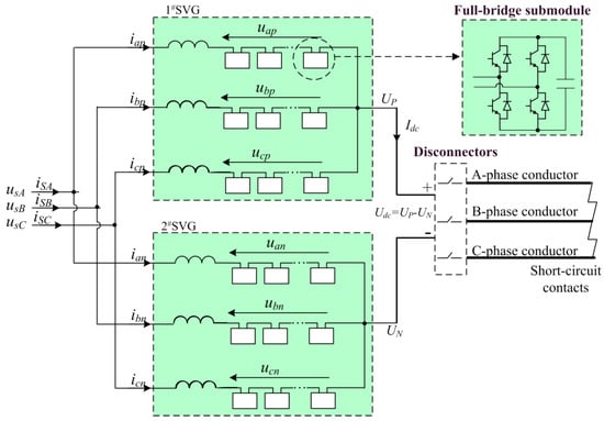
Figure 1.
Circuit configuration of MMC based DC de-icer (MMC-DDI).
Since MMC-DDI can provide both buck and boost functions for DC-link voltage, it theoretically does not require a transformer to supply a wide and adjustable DC output voltage. In the existing literature, the AC terminal of MMC-DDI is directly connected to the distribution network with no transformer. This is considered as a major advantage of the MMC-DDI scheme because it can save the cost and floor area of a transformer, making the device small, light, and compact.
According to the grid requirements, MMC-DDI can have two different operation modes:
- Ice-melting Mode. When there is an ice-covered line to melt in the winter, the disconnectors are close to connect the MMC-DDI and the transmission line together, and the other terminal of the transmission line is artificially three-phase short-circuited to form a DC current loop. Then, the MMC-DDI provides a controlled DC voltage to generate the required current through the ice-covered line. At that time, the operation mode of MMC-DDI is similar to the MMC rectifier station in the VSC-HVDC transmission system, except that the DC-side output voltage almost remains unchanged in the VSC-HVDC system while it may vary with the line parameters in the MMC-DDI system. In addition, the typical control methods for the common MMC system are also applicable to MMC-DDI system, such as the capacitor voltage control, the active and reactive current control, the capacitor voltage balancing control, the circulating current control, etc.
- SVG Mode. When there is no icing line, the de-icing disconnectors can be open circuit. Then, the upper three arms and the lower three arms can operate as two parallel conventional SVGs, and provide reactive power compensation or alleviate other power quality problems.
3. Converter Characteristic of MMC-DDI
3.1. Arm Voltage and Current
Take the A-phase as an example, the dynamic equations of MMC-DDI can be expressed as:
where usA, isA are the AC-side input phase voltage and current of converter. uap, uan are respectively the output voltage of the upper arm and lower arm. iap, ian are respectively the arm current of the upper and lower arms. Up is the electric potential of the neutral point of 1#SVG, relative to the grid neutral point. Un is the electric potential of the neutral point of 2#SVG. R and L represent the equivalent resistance and inductance of the connection reactance in each arm:
where Udc and Idc are the DC-side output de-icing voltage and current of MMC-DDI.
Generally, the voltage and current of each arm are symmetrical, and the circulation current can be effectively suppressed with proper circulation current control method, and the voltage drop across the connection reactance is far less than other items in Equations (1) and (2). As a result, the A-phase arm voltages and currents can be expressed as:
where Um, Im are the root mean square (RMS) values of the AC-side input phase voltage and current of MMC converter. is the angular frequency of gird voltage while ϕ presents the AC-side power factor angle.
Similarly, the B-phase and C-phase arm voltage/current can also be expressed. As shown in Equations (5)–(8), the voltage/current of each arm contains both AC and DC components. Moreover, their peak values are the same for each arm, and can be expressed as
where Iarm_peak, Uarm_peak present the peak values of arm current and arm voltage.
According to Equations (5)–(8), the RMS values of arm voltage and current can be expressed as
where Iarm_RMS, Uarm_RMS present the RMS values of the arm current and arm voltage.
Compared with that of common SVGs, the converter voltage/current of the MMC-DDI has different characteristics:
- (1)
- The arm voltage/current of MMC-DDI contains both DC and AC components, while in the conventional SVG, there is only AC component.
- (2)
- The arm voltage/current no longer equals the AC-side input voltage/current in MMC-DDI.
- (3)
- The peak value of the arm voltage/current is no longer than times of its RMS value.
- (4)
- Due to these differences, although the MMC-DDI is structurally similar to a pair of common star-connected SVGs, their inner converter characteristics are quite different.
3.2. Influence of AC Side Input Voltage
Under normal operating conditions, the AC side input active power of the MMC converter is substantially equal to its DC side output power (neglecting tiny converter loss). According to the power balance between the AC and DC sides, the output DC ice-melting power can be obtained:
where Pdc is the output ice-melting power, cosϕ is AC-side power factor and generally cosϕ = 1.0.
With (11), the AC-side input current of converter can be expressed as
Substituting (12) into (9), the peak values of arm voltage and arm current can be expressed as
According to (13), the influence of AC side input voltage on the arm voltage and current peaks can be plotted and shown in Figure 2. As it shown, for a certain DC ice-melting requirement, with the increasing of AC-side voltage, arm voltage peak increases linearly (but not proportionally) while arm current peak decreases and tends to 1/3 Idc. This is quite different from common SVG. In an SVG, in the case of a certain output reactive power, with the increasing of the AC-side voltage, the arm voltage peak increases proportionally while the arm current peak decreases and tends to 0.
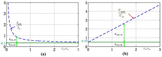
Figure 2.
Influence of the AC side input voltage on the peaks of arm voltage and current (a) on the current (b) on arm voltage.
3.3. Converter Rating of MMC-DDI
In a power electronics system, the converter rating is an important technical indicator because device cost is closely related with the converter rating. For an MMC converter, its converter rating is mainly determined by the arm voltage peak and arm current peak because they largely determine the size and quantity of submodules, and then determines the main hardware of the converter. Therefore, the converter rating of the MMC-based devices can be collectively defined as
where Sc presents the converter rating. n presents the total number of arms. Upi, Ipi are the output voltage and current peak of the i-th arm.
For a conventional star-connected SVG, there are three arms, and the current peak of each arm is approximately equal to the AC side phase current while arm voltage peak is approximately equal to the AC-side phase voltage (ignoring the voltage drop across the connection reactance). Then, its converter rating can be expressed as
where Usp, Isp are respectively the RMS values of AC-side phase voltage and phase current, Sout presents the output apparent power of SVG.
Indeed, Equation (15) also applies to the delta-connected SVGs or an SVG group composed of several converters. In summary, for any SVG, the converter rating can be directly characterized by its rated output power.
For the MMC-DDI, the six arms share the same voltage and current peaks. Substituting Equation (9) into Equation (16), then the converter rating can be expressed as
Compared with equation (15), there are three other items in Equation (16), thus the converter rating characteristics of MMC-DDI are significantly different from that of common SVG.
Substituting Equation (13) into Equation (16) and considering cosϕ = 1.0, the converter rating can be simplified as
With Equation (17), the relationship of the converter rating of MMC-DDI with its AC-side voltage can be calculated and shown as Figure 3. As it shown, under a certain DC-side output voltage and power requirement, the converter rating varies greatly with its AC input voltage. It can be analytically solved that when and only when Um = 0.5 Udc, the converter rating gets its minimum value, and the minimum rating is 2.91 times the output ice-melting power. This conclusion can be expressed as
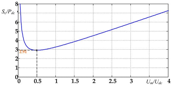
Figure 3.
Relationship of the converter rating of MMC-DDI with its AC-side voltage.
4. The Proposed Optimization Design Method
4.1. General Design Process of IMD
For any type of DC ice melting device, its design process generally follows these steps:
Step 1: According to the line parameters and meteorological conditions of the transmission lines to be melted, calculate the required DC-side output de-icing current, voltage and power, and then determine the rated DC-side output parameters of IMD.
For a given transmission line, its required de-icing current depends on many parameters, such as conductor type, ambient temperature, wind velocity, ice thickness and de-icing duration, etc. The thermal behavior of overhead conductors has been well studied, and some formulas are given to calculate the de-icing current in many standards—for example, IEEE standard [30] and CIGRE standard [31]. Generally, the de-icing current should be greater than the minimum de-icing current and no more than the maximum endure current of the line conductor. For some typical conductor types used in China, the minimum de-icing current and the maximum endure current are shown as Table A1 (see Appendix A). In actual ice melting system, it generally tries to choose the intermediate value of the maximum and minimum values as the rated de-icing current.
After determining the de-icing current, the required de-icing DC voltage can be calculated as
where Iicing is the required de-icing current and Rline is the phase resistance of transmission line. kicing corresponds to the ice-melting mode, kicing = 2 when the de-icing current is passed down one phase conductor and back along another, and kicing = 1.5 when down one and back along the other two [16].
When there are several lines to be melted, the de-icing DC current and voltage of each line can be calculated one by one, and then the rated DC-side output parameters of the IMD are determined by the output DC voltage range, the maximum de-icing current, and the maximum de-icing power.
Step 2: According to the optional voltage levels of the power substation as well as the rated IMD output power, select the proper access voltage of the IMD.
For typical transmission lines, their DC ice-melting power is generally among several MW and hundreds of MW. Within this range, the IMD is usually connected to the low-voltage distribution network of the substation, generally 10 kV or 35 kV in China.
Step 3: According to the DC-side output parameter requirements and the grid access voltage, design the internal structure and parameters of the IMD.
In the process of designing the internal IMD parameters, it is usually necessary to consider both the technical feasibility and the economy.
4.2. The Proposed Circuit Configuration and Its Economic Analysis
According to the above calculation, for a certain ice-melting requirement, the converter rating of MMC-DDI varies greatly with its AC-side voltage. Traditionally, MMC-DDI is directly connected to the grid, thus its AC-side input voltage always equals the grid voltage. This may correspond to a very high converter rating, resulting in poor economy. To solve such a problem, this paper proposes an optimization MMC-DDI configuration structure as shown in Figure 4, i.e., a transformer should be inserted between the grid and the converter under certain conditions. In order to realize this idea, there are two main questions:
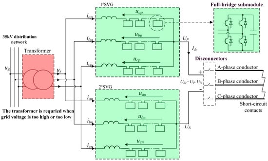
Figure 4.
The proposed configuration structure of MMC-DDI.
- (A)
- When should the transformer be desired and when is it undesired?
- (B)
- If a transformer is inserted, what are the specifications and parameters of the transformer?
According to (11), when the power factor is controlled as cosϕ = 1, the AC-side input apparent power of MMC-DDI always equals its DC side output power regardless of the AC-side voltage. Therefore, if a transformer is inserted, its rating only needs to equal the output de-icing power rather than the converter rating. In order to get the minimum converter rating as shown in (18), the output phase voltage of the transformer can be set as Um = 0.5 Udc, corresponding to a line voltage . In summary, the specification of the transformer can be determined as
where STran is the transformer rating, and Tr is the transformer rating voltage radio.
In order to get the timing of transformer insertion, the cost of converter and transformer should be compared. Since the MMC-DDI is rarely applied, it is difficult to obtain its market cost; here, its cost is estimated by referring to that of SVGs. This is due to three reasons: (1) MMC-DDI is structurally equivalent to a pair of star-connected SVGs, (2) SVG has been widely used and its cost is transparent, and (3) the rating range of common SVGs is wide enough to cover the potential MMC-DDI. Table A2 shows the deal prices of several high capacity SVGs built in China from 2013 to 2018.
As (15) shows, the converter rating of SVG is approximately equal to its rated output power, so the converter cost can be directly evaluated with the SVG deal price. As Table A2 shows, SVG cost is basically proportional to the rating, and its unit cost is around 15,000 $/Mvar. For some SVGs over 60 Mvar, the unit cost is 40% higher. This is because there are only a few applications for such high-power SVGs, thus their R&D cost is higher. Moreover, such high-power SVG usually require higher reliability and larger configuration margin, and this also increases the device cost. For simplicity, here the MMC converter cost is estimated with the average unit price 15,000 $/Mvar.
When a transformer is inserted as Figure 4, the transformer would bring a cost itself. Table A3 shows the deal prices of several 10 MVA-class rectifier transformers built in China. As is shown, the cost of 10 MVA rectifier transformer is about $86,000, about half of the same rating SVG. With the rating growth of transformer, its unit cost decreases rapidly. For a 56 MVA transformer, its unit cost is 4400 $/Mvar and about 1/3 of a similar rating SVG. For a 100 MVA transformer, its unit cost reduces to 3300 $/Mvar and about 1/6 of the same rating SVG.
Based on these cost data, it can be obtained that the cost of a common transformer is much lower than that of the same-rating MMC converter.
In the proposed configuration of MMC-DDI, it can get a minimum MMC converter rating at the cost of an extra transformer. In order to quantitatively compare the economics of the proposed configuration, the costs of MMC-DDI with and without the transformer can be expressed as
where Pno presents the cost of MMC-DDI with no transformer, and presents the cost of the MMC converter when its AC-side voltage is equal to the grid voltage. Pwith presents the cost of the MMC-DDI with a transformer; Ptrans presents the transformer cost. presents the cost of the MMC converter with an AC-side input voltage of .
As long as the cost of MMC-DDI with transformer is lower than that without a transformer, i.e., the reduced converter cost is greater than transformer cost, the proposed configuration structure is cost-effective. At this point, a transformer can be inserted on the AC side of converter to improve the system economy. Otherwise, this is no need to plug in the transformer.
4.3. Applicable Scope of the Proposed Configuration
Compared with the traditional MMC-DDI structure, the proposed MMC-DDI configuration structure requires an extra transformer. It seems that this would increase the cost of the total system, and partially offset the advantages of the MMC topology. However, in fact, the converter rating of traditional MMC-DDI varies greatly with its AC-side voltage, thus the insertion of transformer can sometimes reduce the converter rating and its cost. As long as the reduction of the converter cost is sufficient to offset the transformer cost, the proposed MMC-DDI structure is cost-effective.
According to the cost comparison data of the converter and transformer in the previous section, the unit cost of an MMC converter is generally much higher than that of a conventional transformer, especially for large-capacity converters above 50 MVA. Moreover, the reduced converter rating caused by an introduction of transformer is sometimes much higher than the transformer rating.
In order to obtain quantitative guidance, here an assumption is made of the cost of converter and SVG:
- A
- The converter cost is approximately considered to be proportional to the converter rating.
- B
- The transformer cost is a quarter of the same rating MMC converter cost.
Based on the above quantitative assumption, we can get the following conclusions:
- When the ratio of the grid line voltage to DC-side output voltage exceeds 2.0 or falls below 0.25, the overall cost of MMC-DDI with a transformer is less than that without transformer, i.e., a transformer can be inserted on the AC side of a converter to improve the system economy.
- When the ratio is between 0.25–2.0, the cost of the transformer exceeds its revenue. In that case, no transformer is required.
Indeed, for the common high-voltage transmission lines up to 500 kV, the required ice-melting voltage is generally less than 15 kV. Under such DC voltage range, if the MMC-DDI is connected to a 35 kV network, the grid voltage is more than two times the ice-melting DC voltage. In that case, the proposed MMC-DDI configuration is more applicable than the traditional one. However, if MMC-DDI is connected to a 10 kV distribution network, the grid voltage is usually among 0.25–2.0 times DC voltage, thus the traditional configuration is more applicable. In China, almost all of the distribution network voltage of 500 kV substations is 35 kV. Thus, at least for 500 kV transmission lines, the proposed MMC-DDI configuration is superior to the traditional configuration in most cases.
5. Design Example and Simulation Results
5.1. A Typical Design Example
In order to verify the above analysis and the proposed configuration, a design example of MMC-DDI is given here. For a 500 kV transmission line, the wire type is 4 × LGJ-400, the line length is 40 km, and its single-phase resistance is 0.72 Ω. The minimum ambient temperature along the line is −5 °C, and the maximum wind speed in winter is about 5 m/s. In the 500 kV substation at one end of the transmission line, the distribution grid voltage is 35 kV, corresponding a 20.2 kV phase voltage.
With the data shown in Table A1, the required de-icing current of the above transmission line should be between 3475–4768 A. Within this range, the smaller the current, the longer the de-icing process lasts. Considering a balance between ice-melting rapidity and IMD economics, the rated DC de-icing current can be set as 4.0 kA. Then, with (19), the required de-icing voltage can be calculated as 5.76 kV (2 × 4.0 kA × 0.72 Ω). Thus, the rated de-icing output power is 23.2 MW (= 5.76 kV × 4.0 kA).
With the formulas in Chapter 3, the detailed electrical parameters of above MMC-DDI can be calculated and then listed in Table 1. The voltage and current peaks of the six arms are respectively 31.5 kV and 1.6 kV, thus the converter is equivalent to two conventional star-connected SVGs and each SVG has a 38.5 kV rated line voltage (), a 1.13 kA rated current (), and a 75.4 Mvar rating (). Under the above total arm voltage and arm current, the specifications and numbers of MMC submodules can be freely selected within a certain range. As the 1700 V-level insulated gate bipolar transistor (IGBT) module is widely used in many medium-voltage engineering applications, here the submodule is construed with such IGBT, so the rated capacitor voltage of is set as 900 V and each arm contains 39 submodules. Referring to the SVG price list in Table A2, the converter cost can be estimated as 2.26 million dollar (15,000 $/Mvar × 75.4 × 2 = 2.26 million). With respect to its 23.2 MW output de-icing power, such high cost is too high to be acceptable.

Table 1.
Electrical parameter comparison of the MMC-DDI under conventional configuration and optimized configuration.
If the proposed optimization method is adopted, a 23 MVA–35 kV/5 kV transformer should be inserted between the MMC converter and the 35 kV grid. At this time, the optimized MMC-DDI is mainly composed of an MMC converter and a transformer, and the detailed electrical parameters of MMC-DDI are also listed in Table 1. As Table 1shown, the voltage and current peaks of the six arms are 7.0 kV and 3.2 kV, thus the converter is equivalent to two common SVGs and each SVG has a rated line voltage 8.57 kV (), 2.26 kA rated current () and 33.5 Mvar rating (). Considering the approximate SVG unit cost (15,000 $/Mvar), the converter cost can be estimated as 1.01 million dollar ($15,000 /Mvar × 33.5 Mvar × 2). In addition, in Table A3, the cost of a 24 MVA transformer is $166,000. Then, the total cost of the optimized MMC-DDI can be estimated as 1.18 million dollars.
The above cost comparison results are listed in Table 2. Compared with the cost of the original MMC-DDI with no transformer, the optimized cost of the IMD device has dropped by 48%.
Table 2.
Cost comparison of the MMC-DDI under conventional configuration and optimized configuration.
Besides the cost, the size and weight of the de-icer are also concerned in engineering applications. In practical projects, a complete MMC-DDI system contains not only the connection reactance, the converter valves and the disconnectors as shown in Figure 1, but also inlet cabinet, startup cabinet, control system, cooling subsystem, power distribution cabinet, cable and other auxiliary equipment. The equipment footprint not only includes the size of these devices, but also the insulation distance and other factors. Considering the fact that the main difference of the two MMC-DDI configurations is the converter and transformer, here only the converter chain and transformer are carefully compared.
For simplicity, here refers to a 100 Mvar SVG project built in Hunan in 2016 as a benchmark to compare the size and weight of the two topologies. This project consists of two Y-connected SVGs based on IGBT, and each SVG is 50 Mvar with a 20 kV rated voltage. Its arm current peak is 2125A, and 1.2 times that of that the conventional MMC-DDI configuration. Each SVG contains 63 power submodules, packed in 11 power cabinets. The converter hall is arranged on the first floor, while the cooling system is arranged on the roof. The floorplan of the SVG room is shown in Figure A1 and the main installation parameters of the SVGs are shown in Table A3. As Figure A1 shows, the SVG room covers an area 280 m2, wherein the converter chain occupies 163 m2 (17.6 m × 9.25 m).
The submodule current peak of the above SVG is about 1.2 times that of the conventional MMC-DDI. Here, we adopt the same submodule to form MMC-DDI. Considering that the arm current peak of the optimized MMC-DDI configuration is just twice that of the conventional one, the submodules of the optimized MMC-DDI configuration can be constructed with two parallel SVG submodules. Based on the above ideas, the conventional MMC-DDI requires 234 power modules while the optimized one requires 108 modules, and then their size and weight parameter can be calculated and shown in Table 3. The size and weight of the transformer are based on a 24 MVA rectifier produced for another project, the body size of the transformer is 5.4 m × 4.7 m, but its actual land occupation is set as 8 m × 9 m while considering the insulation distance and ancillary facilities.
Table 3.
Size and weight comparisons of the MMC-DDI under conventional and optimized configuration.
Compared with the conventional MMC-DDI, the optimized scheme required additional 72 m2 to place the transformer, but the converter area is reduced from 296 m2 to 133 m2, namely a reduction of 163 m2. As a result, the overall footprint of MMC-DDI system is reduced by 91 m2, corresponding to a ratio of 22%. It shows that the optimized scheme also has an advantage in the land occupation. On the other hand, the optimized scheme requires a transformer with weight of 38 Ton, but its converter weight is reduced by 35 Ton, thus the total weight was slightly increased by 5 Ton. It shows that the optimized scheme have no advantage in weight. However, the DC de-icer built for high voltage transmission lines up to 500 kV is generally installed in the substations, so this weight disadvantage is still acceptable.
5.2. Simulation Results
To verify the above analysis and calculation on the converter characteristic, a corresponding MMC-DDI system is built in Matlab/Simulink (MathWorks, Natick City, MA, USA), and the simulation parameters are listed in Table A4.
For comparison, a dual-SVGs system (2 × 11.6 Mvar), which is similar to Figure 1 but has a zero DC-side output current reference, is also simulated. Since this article focuses on the converter rating characteristics, the number of submodules in each arm was set as n = 4 to speed up the simulation. This is also sufficient to compare the converter characteristics of the two schemes. The circuit image of the MMC-DDI simulation model built in Matlab/Simulink is shown in Figure A2, and its control block is shown in Figure A3. The simulation results of the dual-SVGs, the conventional MMC-DDI and the optimized MMC-DDI are shown in Figure 5, Figure 6 and Figure 7, respectively.
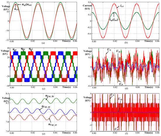
Figure 5.
Simulation results of dual-SVGs system. (a) arm voltage (fileted high frequency ripple), (b) arm current, (c) arm voltage (unfiltered), (d) DC-side voltage (fileted high frequency ripple), (e) capacitor voltage of the first submodule in upper three arms, (f) original DC-side voltage (unfiltered).
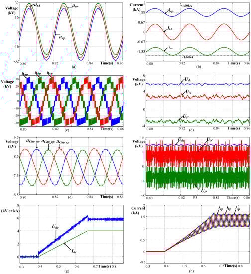
Figure 6.
Simulation results of the conventional MMC-DDI. (a) arm voltage (fileted high-frequency ripple), (b) arm current, (c) arm voltage (unfiltered), (d) DC-side voltage (fileted high frequency ripple), (e) submodule capacitor voltage, (f) DC-side voltage (unfiltered), (g) DC-side output voltage and current during melting-ice startup process, (h) arm current during melting-ice startup process.
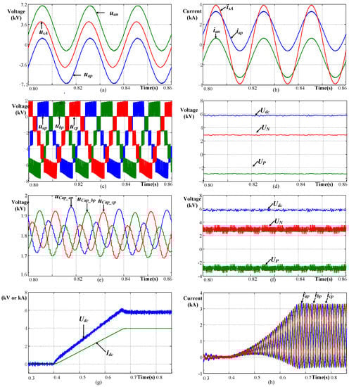
Figure 7.
Simulation results of the optimized MMC-DDI. (a) arm voltage (fileted high-frequency ripple), (b) arm current, (c) arm voltage (unfiltered), (d) DC-side voltage (fileted high frequency ripple), (e) submodule capacitor voltage, (f) DC-side voltage (unfiltered), (g) DC-side output voltage and current during melting-ice startup process, (h) arm current during melting-ice startup process.
As Figure 5a–c shows, in the dual-SVGs system, both the arm current and voltage are positive-negative symmetrical. The arm current equals half of the AC-side input current, while arm voltage is slightly higher than AC-side phase voltage due to the voltage drop across arm reactance. Their peaks are respectively 0.28 kA and 32.0 kV. With (15), the corresponding converter rating can be calculated as 26.9 MVA, just slightly higher than its output reactive power.
As Figure 5d,f shows, in the dual-SVGs system, the center point voltages of two SVGs only have tiny low-frequency component although they have obvious high frequency ripples. These ripples are mainly caused by the separate phase control method adopted in this simulation.
As Figure 5e shows, in the dual-SVGs system, the submodule capacitor voltages are around their set reference 8000 V and have tiny second harmonic fluctuations. The fluctuation amplitude is about 150 V, corresponding to 1% ripple factor.
As Figure 6g and Figure 7g show, the DC-side output voltage and current in the conventional MMC-DDI and the optimized MMC-DDI are almost the same, and they rise gradually to their rated values during the melting-ice startup process. Correspondingly, both the DC and AC components in arm current rise slowly to the expected value. This indicates that the DC-side output voltage of MMC-DDI can be freely regulated within a range not exceeding its rated value, so that it can adapt to the different melting requirement of multiple transmission lines. As Figure 6d and Figure 7d show, the DC-side output voltages are all around their expected value in both the conventional MMC-DDI and optimized MMC-DDI. The only difference is that the voltage ripple of the optimized MMC-DDI is smaller. Since the ice-melting process is mainly based on the Joule heat of the line current, this difference has little effect on the melting results.
As Figure 6a–c shows, in the conventional MMC-DDI that has no transformer, there is a visible DC component in the arm voltage and arm current. Especially in the arm current, the DC component far exceeds AC component. The arm voltage peak is 31.5 kV, which is slightly higher than AC phase voltage, while the arm current peak is 1.6 kA and far higher than the amplitude of its AC component. With (15), the corresponding converter rating can be calculated as 151 MVA, about 6.5 times the DC-side output power.
As Figure 7a–c shows, in the optimized MMC-DDI system that has a transformer, there is an obvious DC component in the arm voltage and current. The arm voltage and current peaks are respectively 7.0 kV and 3.2 kA, corresponding to a 67.2 MVA converter rating. Compared with the original MMC-DDI without a transformer, the arm current peak increases by 100% while the arm voltage peak reduces by 78%, thus the converter rating is only 44% of its original value.
The converter characteristics in such simulation results are consistent with the above analysis and calculation. In addition, the values of the converter voltage and current are also consistent with the theoretical results listed in Table 1. This proves the accuracy of the analysis and calculation on the MMC converter rating present in the paper.
6. Discussion
Concerning the converter rating of MMC-DDI presented in this paper, the goal is to improve the economics of MMC-DDI while maintaining the same output de-icing characteristics. It turns out that, for a given DC ice-melting requirement, the converter rating of MMC-DDI varies greatly with its AC-side input voltage. Then, it is proposed to insert a transformer on the AC side of the MMC converter so that the converter rating as well as its cost can be significantly reduced, and then the economics of MMC-DDI can be improved.
It seems that this proposed configuration scheme is contradictory to traditional understanding of the MMC structure. Conventionally, in the common MMC system such as SVG, the AC side input transformers are expected to be avoided as much as possible.
This difference can be explained due to the converter characteristic of MMC-DDI having significant differences with that of the common MMC system:
- (1)
- In an SVG, both the arm voltage and current contain only an AC component. As a result, in the case of a certain output power, the arm voltage is inversely proportional to arm current, thus the converter rating remains basically constant under any AC-side voltage. In that case, if a transformer was configured on the AC side of MMC converter, it has little influence on the converter rating while increasing a transformer. Therefore, in the common SVG, it tries to avoid a transformer.
- (2)
- In the MMC-DDI, the arm voltage and arm current of converter contain both DC and AC components. As a result of the crossover between the DC and AC components, the converter rating of MMC-DDI varies greatly with its AC-side voltage. Due to such converter characteristics, a transformer can affect the converter rating. In this case, although the introduction of transformer will increase transformer cost, it can cause a cost increment or reduction of the converter. As long as the reduction of the converter cost is sufficient to offset the transformer cost, the introduction of the transformer is cost-effective. In addition, because the unit cost of MMC converter is generally much higher than that of the transformer, the above condition is easy to satisfy under the typical DC ice melting system parameters. Therefore, the optimized configuration scheme proposed in this paper is cost-effective in many cases.
It should be noted that the MMC-DDI can have two operation modes: ice-melting mode and SVG mode. This paper only considers the requirement of the ice melting mode, while not analyzing the operating characteristics of the SVG mode. In the optimization design process, the requirements of SVG mode have not been taken into account. This requirement can be further studied to get more comprehensive optimization results.
7. Conclusions
An MMC-based DC de-icer has been recognized as a promising de-icing solution. Conventionally, the MMC-DDI is recommended to be directly connected to the grid without a transformer.
In this paper, the converter rating of MMC-DDI was quantitatively analyzed. For a given DC ice-melting requirement, the converter rating varies greatly with its AC-side input voltage, and its minimum is 2.9 times the output ice-melting power. When the grid access point voltage is far more than DC de-icing voltage, the conventional MMC-DDI structure requires a far higher converter rating than its output de-icing power, thus the economy of MMC-DDI is very poor.
In order to improve the economy of MMC-DDI, this paper proposes an optimized MMC-DDI configuration structure in which a common two-winding transformer should be inserted at the AC-side of converter in some cases. Thus, the converter rating can be greatly reduced at the cost of an extra transformer. Since the cost of transformer is much lower than the same rating MMC converter, the introduction of transformer is cost-effective in many cases.Actually, for most 500 kV transmission lines, the optimized MMC-DDI configuration is superior to the transformerless MMC-DDI.
A design example and simulation results are given in this paper. In the case of outputting the same de-icing characteristics, the optimized converter rating is reduced from 151 MVA to 68 MVA, and the saved cost on the converter is much higher than the cost of the transformer, thus the total cost of MMC-DDI system is reduced by 48%. At the same time, the total floor space of MMC-DDI system is also greatly reduced by 22%, while, in total, the weight has a small increase.
This analysis and case show that, although the transformer is not technically necessary in an MMC-DDI, it can actually bring considerable benefits related to the total cost and space of MMC-DDI.
This conclusion is conducive to the optimized configuration of modular multilevel DC de-icer, and then to its engineering application for high voltage transmission lines.
Author Contributions
Conceptualization, J.L. and Q.H.; Formal Analysis, Q.H.; Data Curation, X.M., and Y.Z; Writing—Review and Editing, S.Z.; Supervision, Y.T.
Funding
This research was funded by the Science and Technology Project of State Grid Electric Corporation Grant No. 5216A016000P.
Conflicts of Interest
The authors declare no conflict of interest.
Appendix A
Table A1.
The minimum de-icing current and maximum endure current for typical power lines [5].
Table A1.
The minimum de-icing current and maximum endure current for typical power lines [5].
| Conductor Type | Min. De-Icing Current (A) (−5 °C, 5 m/s, 10 mm, 1 h) | Max. Endure Current(A) (5 °C, 0.5 m/s, No Icing) |
|---|---|---|
| LGJ-4 × 400/50 | 3475 | 4764 |
| LGJ-2 × 500/45 | 1989 | 2698 |
| LGJ-2 × 240/40 | 1218 | 1716 |
| LGJ-1 × 240/40 | 609 | 858 |
| LGJ-1 × 185/45 | 515 | 733 |
| LGJ-1 × 150/35 | 441 | 633 |
| LGJ-1 × 95/55 | 345 | 500 |
Table A2.
Deal prices of several typical SVG projects in China from 2013 to 2018.
Table A2.
Deal prices of several typical SVG projects in China from 2013 to 2018.
| No. | Project Location | Rated Voltage (kV) | Rating (MVA) | Deal Price 1 ($1000) | Unit Cost (1000 $/MVA) |
|---|---|---|---|---|---|
| 1 | Kunming, Yunnan | 35 | 10 | 154 | 15.4 |
| 2 | Zhangjiakou, Hebei | 35 | 12 | 175 | 14.6 |
| 3 | Huimin, Shandong | 35 | 15 | 215 | 14.4 |
| 4 | Huangpi, Hubei | 35 | 16 | 251 | 15.7 |
| 5 | Tongyu, Gansu | 35 | 20 | 269 | 13.5 |
| 6 | Hua County, Henan | 35 | 20 | 257 | 12.8 |
| 7 | Chenzhou, Hunan | 10 | 20 | 330 | 16.5 |
| 8 | Qiaojia, Yunnan | 35 | 30 | 385 | 12.8 |
| 9 | Linwu, Ningxia | 35 | 40 | 458 | 11.5 |
| 10 | Dabancheng, Xinjiang | 35 | 50 | 615 | 12.3 |
| 11 | Yinan, Shandong | 35 | 60 | 1023 | 17.1 |
| 12 | Haixi, Xinjiang | 35 | 60 | 1154 | 19.2 |
| 13 | Hami, Xinjiang | 35 | 80 | 1508 | 18.8 |
| 14 | Huaping, Yunnan | 35 | 100 | 2109 | 21.1 |
| 15 | Xiangtan, Hunan | 35 | 120 | 2615 | 21.8 |
1 The deal price covers a complete set of SVG equipment (including the converter chain, connection reactance, startup circuit, cooling system, control system and other ancillary facilities) and its technical service.
Table A3.
Deal prices of several 10 MVA-class rectifier transformers in China.
Table A3.
Deal prices of several 10 MVA-class rectifier transformers in China.
| No. | Project Location | Rated Voltage (kV) | Rating (MVA) | Deal Price ($1000) | Unit Cost (1000 $/MVA) |
|---|---|---|---|---|---|
| 1 | Baoding, Hebei | 10/5 | 10 | 86 | 8.6 |
| 2 | Changsha, Hunan | 10/7 | 14 | 110 | 7.8 |
| 3 | Changsha, Hunan | 35/6 | 24 | 166 | 6.9 |
| 4 | Xinyu, JiangXi | 35/12 | 56 | 246 | 4.4 |
| 5 | Chongqing | 35/15 | 86 | 284 | 3.3 |
| 6 | Zhuzhou, Gansu | 35/17 | 100 | 323 | 3.2 |
| 7 | Hengyang, Hunan | 35/19 | 120 | 361 | 3.0 |
Table A4.
Simulation parameters of the two MMC-DDI and dual-SVG systems.
Table A4.
Simulation parameters of the two MMC-DDI and dual-SVG systems.
| Parameter | Symbol | Dual-SVG | Conventional MMC-DDI | Optimized MMC-DDI |
|---|---|---|---|---|
| AC-side rated voltage | US | 35 kV | 35 kV | 5 kV |
| AC-side rated current | IM | (0.38 kA) 2 | (0.38 kA) | (2.68 kA) |
| AC-side rated power | +23.2 Mvar | (23.2 MW) | (23.2 MW) | |
| Arm inductance | L | 35 mH | 35 mH | 1 mH |
| Arm equivalent resistance | R | 0.1 Ω | 0.1 Ω | 0.02 Ω |
| DC-side output de-icing voltage | Udc | 0 | (5.8 kV) | (5.8 kV) |
| DC-side output de-icing current | Idc | 0 | 4.0 kA | 4.0 kA |
| Resistance of de-icing line | Rdc | - | 1.45 Ω | 1.45 Ω |
| Inductance of de-icing line | Lline | - | 32 mH | 32 mH |
| Submodule number of each arm | N | 4 | 4 | 4 |
| Submodule capacitance | Ccap | 4 mF | 4 mF | 10 mF |
| Submodule capacitor voltage | Ucap | 9.0 kV | 8.0 kV | 1.8 kV |
| Switching frequency | 500 Hz | 500 Hz | 500 Hz |
2 The parameters in parentheses indicate the calculated value, while the parameters in parentheses indicate the values directly set in the simulation.
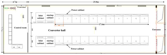
Figure A1.
Floorplan of 100 Mvar SVG room in 500 kV Chuanshan substation.
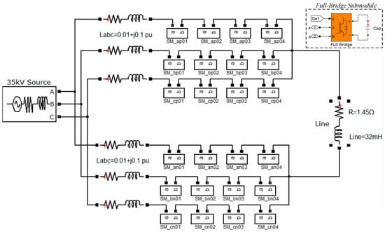
Figure A2.
The circuit image of MMC-DDI simulation model built in Matlab/Simulink.
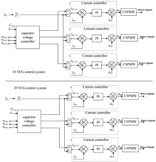
Figure A3.
The control block of MMC-DDI simulation model built in Matlab/Simulink.
References
- Joe, C.P.; Phillip, L. Present State-of-the-Art of Transmission Line Icing. IEEE Trans. Power Appar. Syst. 1982, 8, 2443–2450. [Google Scholar]
- Farzaneh, M.; Savadjiev, K. Statistical analysis of field data for precipitation icing accretion on overhead power lines. IEEE Trans. Power Deliv. 2005, 2, 1080–1087. [Google Scholar] [CrossRef]
- Volat, C.; Farzaneh, M.; Leblond, A. De-icing/Anti-icing Techniques for Power Lines: Current Methods and Future Direction. In Proceedings of the 11th International Workshop on Atmospheric Icing of Structures, Montreal, QC, Canada, 13–16 June 2005. [Google Scholar]
- Brostrom, E.; Ahlberg, J.; Soder, L. Modelling of Ice Storms and their Impact Applied to a Part of the Swedish Transmission Network. In Proceedings of the 2007 IEEE Lausanne Power Tech 2007, Lausanne, Switzerland, 1–5 July 2007; pp. 1593–1598. [Google Scholar]
- Wang, J.; Fu, C.; Chen, Y.; Rao, H.; Xu, S.; Yu, T.; Li, L. Research and application of DC de-icing technology in China southern power grid. IEEE Trans. Power Deliv. 2012, 3, 1234–1242. [Google Scholar] [CrossRef]
- Laforte, J.L.; Allaire, M.A.; Laflamme, J. State-of-the-art on power line de-icing. Atmos. Res. 1998, 46, 143–158. [Google Scholar] [CrossRef]
- Motlis, Y. Melting ice on overhead-line conductors by electrical current. In Proceedings of the CIGRE SC22/WG12, Paris, France, 26–30 August 2002. [Google Scholar]
- Farzaneh, M.; Jakl, F.; Arabani, M.P.; Eliasson, A.J.; Fikke, S.M.; Gallego, A.; Haldar, A.; Isozaki, M.; Lake, R.; Leblond, L.; et al. Systems for Prediction and Monitoring of Ice Shedding, Anti-Icing and De-Icing for Power Line Conductors And Ground Wires; CIGRE: Paris, France, 2010. [Google Scholar]
- Davidson, C.C.; Horwill, C.; Granger, M.; Dery, A. A power-electronics-based transmission line de-icing system. In Proceedings of the 8th IEE International Conference on AC and DC Power Transmission, London, UK, 28–31 March 2006; pp. 135–139. [Google Scholar]
- Dery, A.; Granger, M.; Davidson, C.C.; Horwill, C.; Dery, A.; Granger, M.; Davidson, C.C.; Horwill, C. An Application of HVDC to the de-icing of Transmission Lines. In Proceedings of the 2005/2006 IEEE PES Transmission and Distribution Conference and Exhibition, Dallas, TX, USA, 21–24 May 2006; pp. 529–534. [Google Scholar]
- Fu, C.; Rao, H.; Li, X.; Chao, J.; Tian, J.; Chen, S.; Zhao, L.; Xu, S.; Ma, X. Development and application of DC deicer. Autom. Electr. Power Syst. 2009, 63, 118–119. [Google Scholar]
- Rao, H.; Li, L.; Li, X.; Fu, C. Study of DC based De-icing Technology in China Southern Power Grid. South. Power Syst. Technol. 2008, 2, 7–12. [Google Scholar]
- Davidson, C.C.; Horwill, C.; Granger, M.; Dery, A. Thaw point. Power Eng. 2007, 21, 26–31. [Google Scholar] [CrossRef]
- Jing, H.; Nian, X.; Fan, R.; Liu, D.; Deng, M. Control and switchover strategy of full-controlled ice-melting DC power for ice-covered power lines. Autom. Electr. Power Syst. 2012, 36, 86–91. [Google Scholar]
- Zhao, G.S.; Li, X.-Y.; Fu, C.; Li, X.-L.; Wang, Y.H.; Xia, W. Overview of de-icing technology for transmission lines. Power Syst. Prot. Control 2011, 39, 148–154. [Google Scholar]
- Bhattacharya, S.; Xi, Z.; Fardenesh, B.; Uzunovic, E. Control reconfiguration of VSC based STATCOM for de-icer application. In Proceedings of the 2008 IEEE Power and Energy Society General Meeting, Pittsburgh, PA, USA, 20–24 July 2008; pp. 1–7. [Google Scholar]
- Hagiwara, M.; Akagi, H. Control and Experiment of Pulsewidth-Modulated Modular Multilevel Converters. IEEE Trans. Power Electron. 2009, 24, 1737–1746. [Google Scholar] [CrossRef]
- Rohner, S.; Bernet, S.; Hiller, M.; Sommer, R. Modulation, Losses, and Semiconductor Requirements of Modular Multilevel Converters. IEEE Trans. Ind. Electron. 2010, 57, 2633–2642. [Google Scholar] [CrossRef]
- Lesnicar, A.; Marquardt, R. An innovative modular multilevel converter topology suitable for a wide power range. In Proceedings of the 2003 IEEE Bologna Power Tech Conference Proceedings, Bologna, Italy, 23–26 June 2003. [Google Scholar]
- Martinez-Rodrigo, F.; Ramirez, D.; Rey-Boue, A.B.; de Pablo, S.; Lucas, L.C.H. Modular Multilevel Converters: Control and Applications. Energies 2017, 11, 1709. [Google Scholar] [CrossRef]
- Mehrasa, M.; Pouresmaeil, E.; Zabihi, S.; Mehrasa, M.; Pouresmaeil, E.; Zabihi, S.; Caballero, J.C.T.; Catalão, J.P.S. A Novel Modulation Function-Based Control of Modular Multilevel Converters for High Voltage Direct Current Transmission Systems. Energies 2016, 9, 867. [Google Scholar] [CrossRef]
- Perez, M.A.; Bernet, S.; Rodriguez, J.; Kouro, S.; Lizana, R. Circuit topologies, modeling, control schemes, and applications of modular mul-tilevel converters. IEEE Trans. Power Electron. 2015, 1, 4–14. [Google Scholar] [CrossRef]
- Flourentzou, N.; Agelidis, V.G.; Demetriades, G.D. VSC-Based HVDC Power Transmission Systems: An Overview. IEEE Trans. Power Electron. 2009, 24, 592–602. [Google Scholar] [CrossRef]
- Mohammadi, H.P.; Bina, M.T. A Transformerless Medium-Voltage STATCOM Topology Based on Extended Modular Multilevel Converters. IEEE Trans. Power Electron. 2011, 26, 1534–1545. [Google Scholar]
- Mei, H.; Liu, J. A Novel DC Ice-melting Equipment Based on Modular Multilevel Cascade Converter. Autom. Power Syst. 2013, 37, 96–102. [Google Scholar]
- Thitichaiworakorn, N.; Hagiwara, M.; Akagi, H. Experimental verification of a modular multilevel cascade inverter based on double-star bridge cells. IEEE Trans. Ind. Appl. 2014, 50, 509–519. [Google Scholar] [CrossRef]
- Li, B.; Shi, S.; Xu, D.; Wang, W. Control and Analysis of the Modular Multilevel DC De-Icer with STATCOM Functionality. IEEE Trans. Ind. Electron. 2016, 9, 5465–5476. [Google Scholar] [CrossRef]
- Ning, Y.; Zheng, J.; Chen, Z. Application of star-connected cascaded STATCOM in DC ice-melting system. Autom. Electr. Power Syst. 2015, 27, 1920–1922. [Google Scholar]
- Guo, Y.; Xu, J.; Guo, C.; Zhao, C.; Fu, C.; Zhou, Y.; Xu, S. Control of full-bridge modular multilevel converter for dc ice-melting application. In Proceedings of the 11th IET International Conference on AC and DC Power Transmission, Birmingham, UK, 10–12 February 2015; pp. 1–8. [Google Scholar]
- IEEE Standard for Calculating the Current-Temperature Relationship of Bare Overhead Conductors; IEEE Std 738-2012; IEEE Standards Association: Piscataway, NJ, USA, 2013; pp. 1–72.
- CIGRE. Thermal Behavior of Overhead Conductors. Electra 1992, 144, 107–125. [Google Scholar]
© 2018 by the authors. Licensee MDPI, Basel, Switzerland. This article is an open access article distributed under the terms and conditions of the Creative Commons Attribution (CC BY) license (http://creativecommons.org/licenses/by/4.0/).