Design of A Novel Line Start Synchronous Motor Rotor


1
Department of Electronics and Automation, Merzifon Vocational School, Amasya University, Amasya TR 05300, Turkey
2
Department of Mechatronics Engineering, Faculty of Engineering and Natural Sciences, Gaziosmanpaşa University, Tokat TR 60150, Turkey
*
Author to whom correspondence should be addressed.
Electronics 2019, 8(1), 25; https://doi.org/10.3390/electronics8010025
Submission received: 29 November 2018
/
Revised: 13 December 2018
/
Accepted: 21 December 2018
/
Published: 26 December 2018
(This article belongs to the Special Issue Applications of Power Electronics)
Abstract
:Line start permanent magnet synchronous motors (LS-PMSM) are preferred more and more in industrial applications, because they can start on their own and because of their high efficiency. In this study, a new LS-PMSM rotor typology is suggested, which is modelled using surface mount permanent magnets, in which two different slot types have been used together. The rotor of an asynchronous motor on the industrial market in the IE2 efficiency segment has been remodeled in the study, resulting in an increase in motor efficiency from 85% to 91.8%. A finite elements software was used for determining motor design and performance, in addition to analytical methods.
1. Introduction
Electrical motors have the highest share in electrical consumption for industrial and home applications. Therefore, there are many studies in literature that focus on making electrical motors more efficient. In addition to the electricity consumed by the electrical motors used in all fields, the resources used for motor manufacture are also another significant issue [1,2]. The use of a motor with a large core for obtaining the desired shaft power increases the material used for producing the motor, thereby directly affecting production cost [3].
There are many products that can respond to the operating conditions in the current electrical motors market. A necessity has emerged for regulating the electrical motor market with various standards, as there are many different products in the market with different brands that can replace one another. Many regulations are ongoing regarding the frame dimensions, operating characteristics, and operating conditions for these electrical motors, which are put on the market with standards that are also accepted by electrical motor producers [4]. Many standards, such as EPAct (1992), CEMEP (1998), and IEC 60034-2-1/60034-30-1 (2008), until now, have been suggested to arrange the market and increase product mobility [4,5]. Moreover, now, more efficient motors with a higher performance can be put on market, with the developing technology and the revisions that are made in the standards subject to these changes. According to the widely accepted IEC electrical motor standards, motor efficiencies are classified as IE1 for standard efficiency, IE2 for high efficiency, IE3 for premium efficiency, and IE4 for super premium efficiency [6].
Induction motors (IMs), which are preferred because of their robustness and requirement for less maintenance are put on the market with an efficiency of IE3 and below. It is not possible to produce these motors with an efficiency above IE3 because of technological and material limitations [7]. However, high-power electrical motors can be produced, which provide a higher efficiency and power factor by placing high performance permanent magnets on the IM rotor, the cost of which continues to decrease every day [8]. These motors with a permanent magnet in their rotor and an IM squirrel cage are known in the literature as line start permanent magnet synchronous motors (LS-PMSM). In addition to being robust and requiring less maintenance, like IMs, LS-PMSMs are also able to provide efficiencies of above IE3, thanks to the permanent magnets in their rotor [9].
While the LS-PMSM may start asynchronously via direct power from the line, like IMs, because of the squirrel cage in their rotors, contrary to IMs, which generate variable rpm subject to load, they can continue to operate at a constant speed after reaching a synchronous speed. A rotor current is not induced on the cage, as the squirrel cage does not cut off the stator magnetic field in the motor, which continues to rotate at a constant speed (synchronous speed) because of the effect of the extra magnetic flux generated by the permanent magnets, which leads to reducing the electromagnetic losses on the rotor to an almost non-existing level (when harmonics are considered) [10,11].
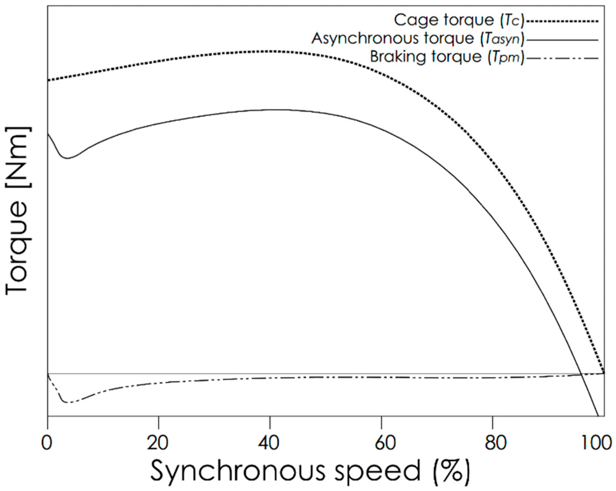
The LS-PMSMs, which can run up with the cage torque generated by the aluminum start winding (squirrel cage) in their rotor, are able to generate an opposite braking torque thanks to the permanent magnets placed on the rotor. Thus, the electromagnetic torque generated by the motor during the synchronization period is comprised of two torques, as the cage torque () and magnet torque, which is in the opposite direction (). The and torque components generated at the time of starting are expressed by Equations (1) and (2), respectively [12,13,14].
The total electromagnetic torque () can be determined using Equation (3).
Figure 1 shows the torque components of the LS-PMSM. The dotted curve in the figure represents the torque generated by the start cage without a permanent magnet (), and the dashed line represents the braking torque generated by the permanent magnets (). The asynchronous torque () generated by electromagnetic torque (), which is the sum of and , is represented by a normal line. The cage torque () should overcome the braking torque () generated by the permanent magnets, the load torque (), and motor inertia () in order for the synchronization process in LS-PMSM to be successful.
The successfully synchronized motor passes on to a steady state operation in order to continue rotating at a synchronous speed. The torque generated because of the currents during the steady state operation is as given in Equation (4).
In addition, if the angle between the EMF and terminal voltage is denoted by , the synchronous torque when the resistances are neglected can be expressed as in Equation (5).
There are many studies in the literature for improving the start performance of LS-PMSMs under different loads and line voltages, and for ensuring that the motor operates more efficiently after synchronization. It is observed that these studies have focused on improving the motor dynamic model, which expresses the operating characteristic of the motor better, as well as the determination and optimization of the design parameters with an impact on the synchronization performance of the motor [15,16,17,18,19].
A new LS-PMSM rotor design is presented in this study, with a high producibility, low cost, high efficiency, and with low maintenance requirement. A new squirrel cage using two different slot structures for improving motor run up and synchronization performance, along with surface mount permanent magnets, have been used in this suggested rotor design for increasing performance. The purpose of the study is to remodel the rotor of an already existing IM with IE2 1500 rpm 5.5 kW rated power. The ANSYS® Electromagnetics Suite finite elements software environment, which has proven itself in academic studies, was used for modelling the motor, in addition to the analytical models. The MathWorks Inc. MATLAB® development environment was also used in addition to Electromagnetics Suite for determining the motor performance characteristics, as well as for the optimization studies.
2. LS-PMSM Design
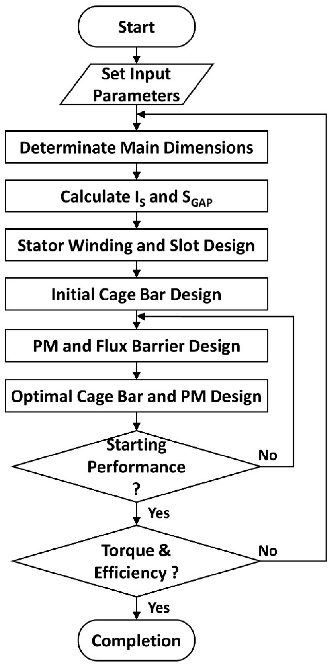
The IM design process is quite complex, but it has been discussed many times in the literature. LS-PMSMs are structurally similar to IMs to a great extent; however, their design process is more complex because of the inclusion of permanent magnets in their structure. It is a preferred method of LS-PMSM design to initially design the IM that will provide the desired power, and then placing the permanent magnets to the rotor [19,20,21,22]. Works for improving the slot and magnet design should be carried out in order to reach the desired motor design. Figure 2 shows the optimal LS-PMSM design algorithm [20,23].
It is very practical to start the design process by first determining the main dimensions of the motor (stator outer diameter, ; stator inner diameter, ; stack length, ; and air gap, ). The air gap power of the motor can be determined subject to the output power of the motor, after the main dimensions of the motor have been determined. Stator winding and slot design can be carried out using the determined airgap power (). Finally, the rotor design is carried out to complete the design process.
The primary goal in LS-PMSM design is to ensure that the motor can synchronize by itself. The synchronization performance should be reevaluated by updating the permanent magnet and starting the winding design of the motor, which failed in the synchronization process. The shaft torque characteristic and efficiency during the steady state operation are controlled for the motor, which provides a satisfactory synchronization performance. The design process should be repeated by updating the main dimensions of the motor and/or the permanent magnet design for the motor designs with an unsatisfactory torque characteristic or efficiency.
2.1. Determining the Main Dimensions of the Machine
Determining the main dimensions of the LS-PMSM should be carried out in an attentive manner. It becomes very easy to place the permanent magnets and slots to the main motor core when the motor core is selected as larger than necessary. However, this preference leads to the use of more production (lamination steel, aluminum, copper, etc.), thereby resulting in a motor design with a heavier core and a larger production cost. It may become a problem to fit a slot design and permanent magnet that will meet the desired airgap power if the motor core is selected as being smaller than necessary. When it is considered that the motor core is affected by the magnetic field in addition to the magnetic flux generated by the permanent magnets, especially the stator yoke, the saturation increases excessively, thereby leading to a significant decrease in motor efficiency. Finally, the accordance of the selected motor core dimensions with the standard frame dimensions is important for the compliance of the design with the standards.
In this study, the stator design was obtained from a current industrial IEC standard compliant IM. Thus, the main dimensions of the motor were determined by taking the stator design as reference. Therefore, it was ensured that the new design is compliant with the IEC motor standards. The main reference motor dimensions in the study have been given in Table 1.
, , and are already known in the study, as the stator design has been directly taken from a standard IM (Table 1). Additionally, the air gap has to be re-determined for the new rotor design. Equation (6) is used in the literature [20] for determining the air gap in the machines with two or more poles.
The air gap, , stated here, is the ideal value required for the modeling of standard IM. As surface mount permanent magnets are used in this study, the risks for braking the torque generated by the magnets and the demagnetization of the permanent magnets increase when the air gap that is selected is very small. Therefore, it may be necessary to select this value as greater than the analytical values.
Another parameter that should be set during the design process is the targeted flux density for the air gap (). It is suggested [24] that the air gap flux density should be between (0.7–0.9 T). This value is taken into consideration when modeling the rotor cores and determining the dimensions of the permanent magnets.
2.2. Stator Design
This study aims to make an industrial asynchronous motor more efficient only by redesigning its rotor. For this purpose, the stator design was taken from a 5.5 kW IE2 asynchronous motor. Details regarding the 36-slot stator design have been given in Table 2.
The label information for the standard IE2 IMs taken as reference have been given in Table 3.
2.3. Rotor Design
The rotor design for LS-PMSM can be examined under the two main headings of slot design and permanent magnet design. Determining the preferred rotor topology first, during the design process, followed by the design of start windings, and finally the placement of the required permanent magnets to the rotor core, makes the design process very practical. Many different rotor designs have been presented for LS-PMSM development until today [25,26,27,28]. It can be observed in the studies carried out that surface PM or interior PM type designs may be preferred [29,30]. Placing the slots on the regions left over from the permanent magnet may be problematic in designs, such as in interior PMs, where permanent magnets are placed away from the air gap. It may be necessary to readjust the slot design so as to reduce the slot height, especially in designs where permanent magnets are positioned behind the slot. In addition, part of the magnetic field generated by the permanent magnets placed away from the air gap only close in the rotor, thereby resulting in losses in the magnet magnetic field leading to an overheating of the rotor. This undesired situation is overcome by placing a flux barrier at the magnet tip. This brings forth the necessity to leave an additional space on the rotor core for the flux barrier. Placing the permanent magnet on the rotor core without deforming is another problem that needs to be overcome. However, it has been observed in the studies carried out that interior PM typologies are preferred more, as there is a lower risk for the permanent magnets to be deformed while the motor is in operation [25,26,27,28].
A new surface permanent magnet topology has been preferred in this study, which is to place the desired number of permanent magnets on the rotor. Also, it is more flexible with regard to the slot design. Thanks to this preference, it has been possible to place the permanent magnets on the rotor core without any deformation. In addition, the permanent magnet magnetic flux losses have been minimized and they have been directed to the airgap. Of course, this has led to giving more attention to the rotor cage design in order to ensure that the permanent magnets that are closer to the air gap do not have an adverse impact on the motor start. The torque fluctuations due to the impact of the permanent magnets are another issue that should be taken into consideration [31,32].
The most important issue that requires attention in the design of the surface mount permanent magnets is to select the magnet dimensions (thickness and height) properly. While a very thin permanent magnet preference leads to an increased risk of demagnetization, a thick permanent magnet preference results in the braking torque generated by the permanent magnet to have an adverse impact on the motor start [22,33].
The leakage flux and fringing effects may be neglected when it is taken into consideration that the flux generated by the permanent magnets in the surface mount permanent magnet motors directly passes onto the air gap, thus it is accepted that . Thereby, Equations (7) and (8) can be written [33].
The rotor bar and end ring circuits to be used in dimensioning the motor start windings can be determined by way of Equations (9) and (10) [24].
where
As a result, the acquired rotor bar and end ring area can be calculated via Equations (12) and (13), respectively.
where and indicate the rotor bar and end ring current densities, respectively. It is suggested in the literature [24] that this value should remain between the 3–6.5 A/mm2 interval for aluminum rotor cages.
In light of the acquired data, the rotor tooth width, , can be calculated as given in Equation (14) [20].
The LS-PMSM’s may start by overcoming the motor inertia and the braking torque generated by the permanent magnets. This puts forth the necessity for a high-performance cage design in order to prevent the motor from having synchronization problems. In addition, the start windings have to re-synchronize the motor in case the motor speed is below the synchronous speed at the time of starting.
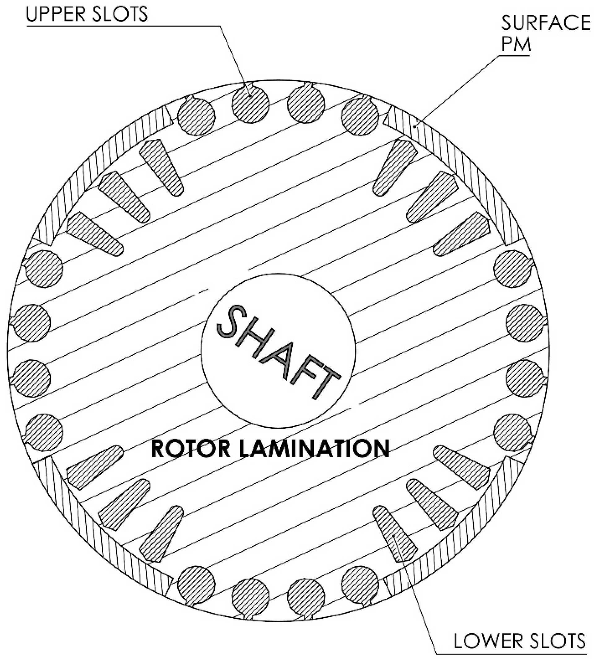
The slot structures that determine the motor torque characteristic are standardized by NEMA with class A, B, C and D [34]. According to the NEMA standard classes A and B are used in general purpose motors. Also, Class C and D are preferred in applications requiring higher starting torque. As a result, a new rotor typology making use of both of the slot types is suggested in this study, to ensure that both the motor start and synchronization performances are high (Figure 3).
A total of 16 NEMA D class upper slots have been placed near the permanent magnets in the suggested model, by taking into consideration the speeding characteristic of LS-PMSM. In addition, 12 NEMA B class lower slots have been placed under the permanent magnets, in order to help re-synchronization in case the motor drops below the synchronous speed during steady state operation, and also in order to support the motor start. Care was also given to ensure that the cross-sections of both slot types are as close to each other as possible, for ensuring the homogeneous distribution of the rotor current induced on the start windings to the rotor bars. As was the case for the stator, M330 50A steel material was used for the rotor as well during the design procedure. Also, N45SH neodymium magnets are preferred for PM design.
2.4. Optimization of the Suggested Design
The motor operating characteristic in the LS-PMSM design depends to a large extent on the permanent magnet and slot design. So much so that a significant increase in the motor performance can be attained with a permanent magnet design with the correct geometrical position and geometry, in addition to reducing the cogging. In addition, determining the proper rotor slot geometry is another important issue to ensure that the motors start themselves.
It can be seen in Figure 4a that the analytically designed model has been synchronized successfully at 150 ms. The shaft torque generated by the motor during starting (0–150ms) and steady state (150–200 ms) periods can be seen in Figure 4b. The = 19.98 (SI) generated during the steady state operation indicates that an excessively vibratory shaft torque has been generated (the SI unit corresponds to /). The stator current and motor efficiency were determined during the steady state operation as = 9.6 A and = 91.14%, respectively. When this efficiency value is compared with the 85% value obtained with the standard IM rotor, it can be observed that an efficiency increase of 6.14% has been attained. IE3 efficiency levels have been reached with this efficiency value, obtained using the analytically modelled design without any optimization.
The objective with the optimization studies carried out was to ensure that the motor efficiency exceeds 91.9% (IE4), by determining the proper design parameters. The optimized design parameters can be seen in Figure 5.
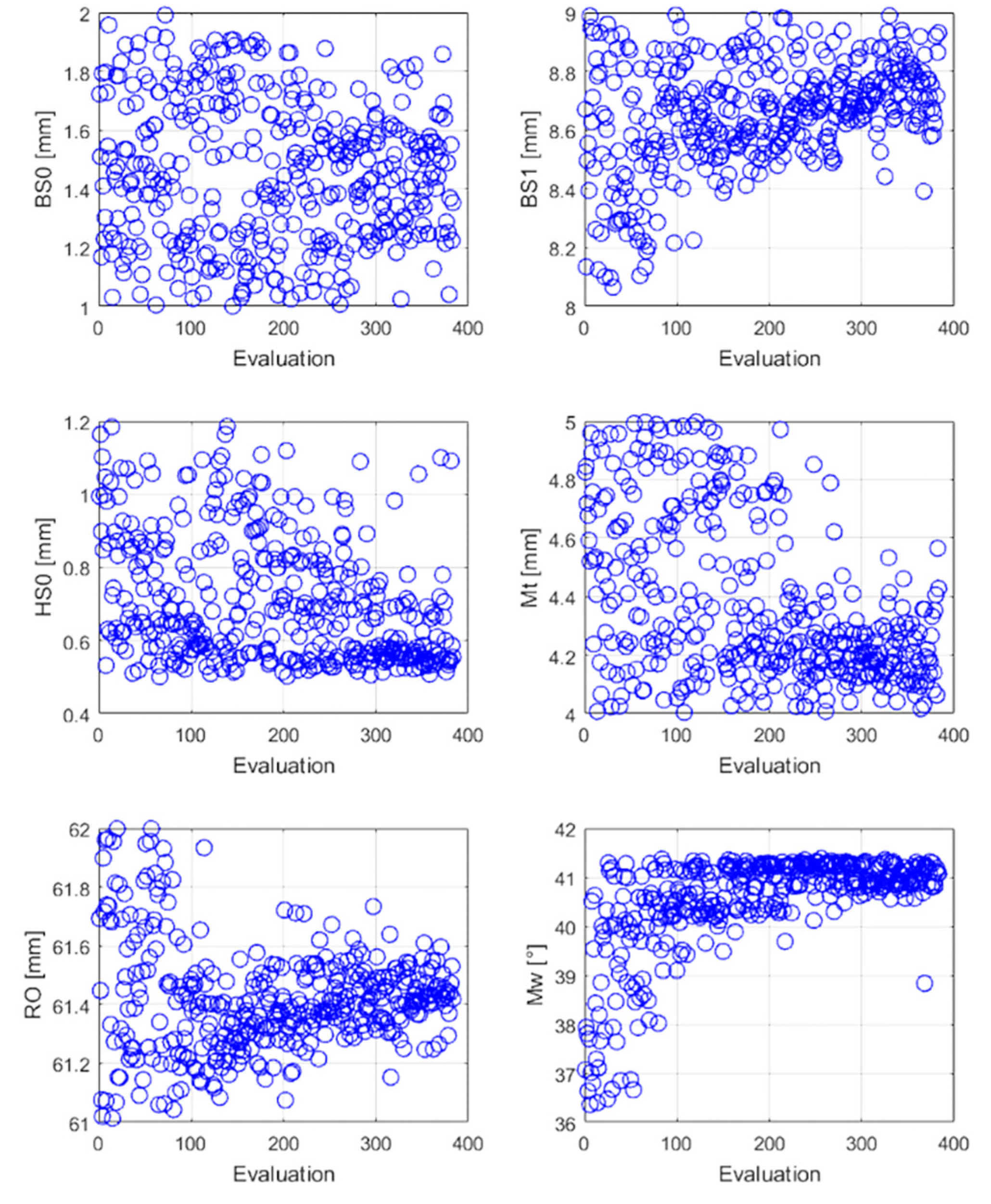
and in Figure 5 stand for the magnet thickness and width, respectively; denotes the slot gap for the rotor upper slots; represents the slot depth; and denotes the slot diameter. Finally, the rotor diameter () was also included in the optimization studies for determining the optimum air gap value. The parameters used in the optimization study are shown in Table 4 together with their min. and max. values.
2.4.1. Optimization of the Model Suggested via Genetic Algorithm
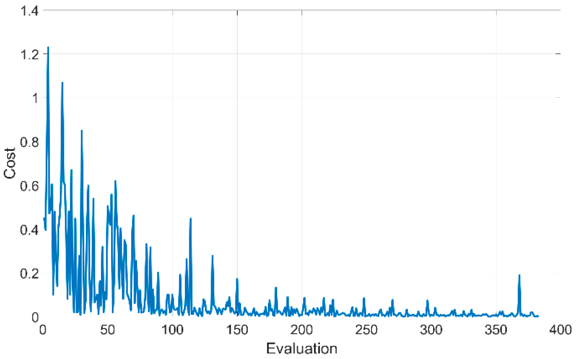
It can be observed when studies on geometric optimization are examined, that, in general, the genetic algorithm (GA) is used for determining the optimum data from among large data sets. GA has also been preferred in this study during the optimization work carried out for determining the motor design parameters with the targeted efficiency characteristics.
The cost function obtained as a result of optimization via the genetic algorithm has been presented in Figure 6 as a graph. As can be seen from the graph, the targeted efficiency (92%) was reached after 383 evolutions.
Figure 7 shows the design parameters processed via GA and the distribution of the parameters. It can be understood upon examining the graph that the values of , , , , and do not have a homogeneous distribution, and the optimization study has focused more on certain value intervals. In addition, the graph presented indicates that the impact of the value on motor performance is quite low. In conclusion, the targeted efficiency was reached as a result of GA optimization at around = 8.5 mm, = 1 mm, = 1.79 mm, = 4.48 mm, = 40.5°, and = 61.30 mm. Moreover, the torque ripples generated by the motor have been decreased down to about = 7.09 (SI), and the motor rated current was determined as = 9.26 A. Table 5 summarizes the change in the design parameters and motor operating characteristic as a result of the GA optimization.
A significant number of analyses were carried out during the optimization studies for reaching an optimum rotor design with a high efficiency. The motor design was evaluated as being two dimensional during the analyses carried out, as it delivers faster solutions, and the analyses were finalized with a Maxwell 2D Transient solver. A Maxwell 3D Transient solver was used during the next stages of the study for a more detailed examination of the model obtained with a high efficiency via GA.
The torque ripples in the motor shaft torque resulted in = 19.98 (SI) in the model, whereas this value was decreased to = 7.08 (SI) in the new design. Optimization works were carried out for the optimization of this value, which was still quite high in the later stages of the study. The component generated especially in the pole transitions generates ripples in the torque, because of the interactions between the permanent magnets and the stator tooth in LS-PMSM’s [35]. It was observed that when the studies for reducing the ripples in the torque were examined, the focus was on the optimization of the stator tooth and/or permanent magnets, production of the skewed stator, or rotors [36,37,38,39,40].
Embedding the permanent magnets to the rotor core in order to decrease their interaction with the stator tooth is a widely used method for optimizing the permanent magnets so as to reduce torque ripples. However, this method cannot be applied on rotor topologies with a surface mount PM. In addition, it is not possible to update the stator slot and tooth structure, as the stator design was taken from an already existing IM.
On the other hand, producing skewed permanent magnet rotors makes it more difficult to place the magnets inside the rotor core, which increases the production costs. Therefore, the focus was on producing a skewed stator core for reducing ripples in torque. Thus, it was aimed at reducing the ripples in the torque by only producing a skewed core without any changes in the stator slot and tooth design.
2.4.2. Reducing Ripples in the Torque Using Skewed Stator
The graph in Figure 8 shows the values generated by the motors modelled with different stator skew angles. It can be seen in the graph that there is no linear relationship between the values, however the lowest values could be generated as = 4.48 (SI), = 2.9 (SI), and = 4.39 (SI). It can also be seen from the graph that the highest efficiency values were obtained as = 91.33%, = 91.29%, and = 91.28%.
As can be seen in Figure 9, showing the impact of s stator skew angle on the motor synchronization performance, the motor has the highest synchronization performance at angles of skew0 and skew8. However, the high torque ripples of around = 7 (SI) are generated for both skew angles, which results in an unacceptable decrease in the motor shaft torque quality. In addition, it was also observed that motor efficiency and performance decreased significantly for at which a satisfactory decrease in the torque ripple was obtained. In conclusion, was preferred as the stator skew angle, because of its satisfactory synchronization performance and lowest torque ripples.
Cogging torque is a torque effect that is generated in the motor shaft, which prevents the rotation of the motor shaft—the impact of which is felt when the motor is idle. This torque component generated because of the permanent magnets on the rotor core is a factor that results in the decrease in the quality of the shaft torque generated by the motor. Figure 10 shows the cogging torque for the and angles, which is generated during the 30° rotation of the motor. As can be seen in the graph, the cogging torque is reduced significantly (67.7%) with a skewed stator motor design. The graph in Figure 11 shows the electromagnetic torque generated by the motor for skew angles of and . As can be seen from the graph a significant improvement in motor torque quality has been attained by preferring angle.
2.5. Analysis of the Suggested Model
At this stage of the study, the performance characteristic will be examined for the motor design with a stator having a skew angle of , modelled using the suggested rotor topology. The most important problem with LS-PMSM’s is the braking torque generated during operation, because of the permanent magnets. This results in issues such as the LS-PMSM’s becoming too sensitive to circumstances, such as the overloading of the motor. Figure 12 shows the starting performance under different motor loads for the skewed stator model suggested. As can be seen from the graph, the motor can reach a synchronous speed of 1500 rpm in 0.3 s at = 35 Nm (Full Load). An overloading of 14% (= 40 Nm) results in the failure of the motor synchronization process.
The graph in Figure 13 shows the current and efficiency values subject to load torque. It can clearly be seen from the graph that the current drawn when the motor is idle is around = 2.3 A. This value increases up to = 9.84 A at an overloading of 40 Nm. The current drawn at ¼ of the load is 2.8 A and 4.3 A at ½ loading. Motor efficiency at ¼ loading increased up to 86% and up to 91% at ½, whereas a maximum value of 91.28% was reached at full load.
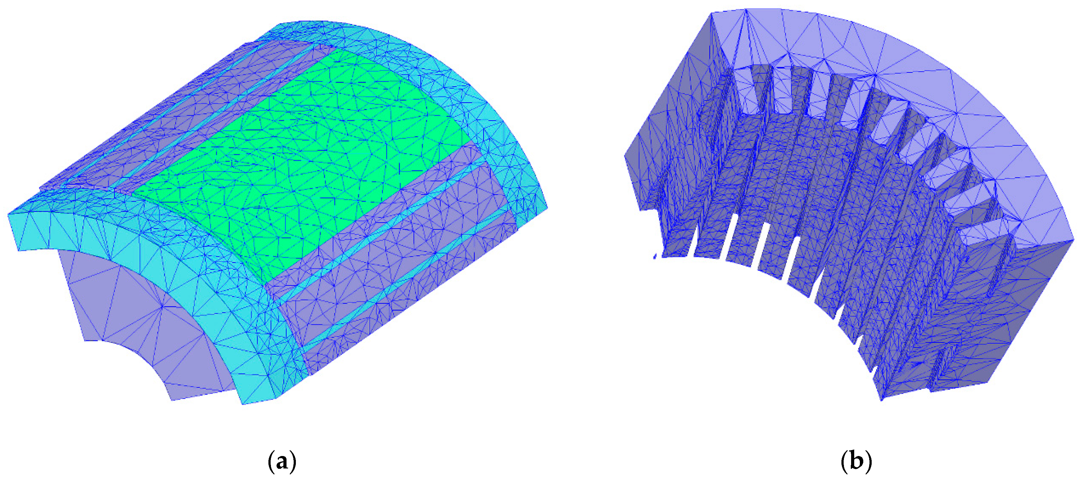
Figure 14 shows the meshed model of the ¼ suggested LS-PMSM. The Tetrahedra mesh structure was used in the simulation analyses. The number of small regions formed in this structure is directly related to the closeness to the correct result. A total of 173,665 regions were created as a result of the mesh processing. While a total of 35,569 regions existed in each stator; 26,133 regions were consisted in the rotor, bar, and magnets. The rest of the regions are located in the defined windings, band, inner-outer regions, and shaft regions.
Figure 15a shows the flux densities in the stator and rotor core during the steady state operation of the motor. As can be understood from the presented figure, the magnetic flux can penetrate deep into the rotor core at high speeds, because of the low frequency of the rotor, which results in an active motor synchronization at lower slots. In addition, it also makes it more difficult for the motor to decrease from a synchronous speed. Even though it is observed in the graph that the flux densities remain in safe limits at the rotor and stator yokes, it can also be observed that the flux accumulations that develop during the steady state period do not exceed the value of 1.9–2 T.
Also, Figure 15b shows the vector distribution of the ¼ suggested model in 2D. As can be seen in the figure, the magnetic flux around the upper slots, lower slots, permanent magnet, and the rotor yoke changes easily.
2.6. Analysis of the Suggested Model Under Quadratic Load
The starting performance of the model, which is suggested with Figure 12 in the previous section, was discussed under a constant load; it has been observed that the suggested motor cannot be synchronized under a constant load of = 40 Nm. This result, which has been acquired from analysis studies, is quite low if compared to the 230% of the starting torque generated by the reference motor.
The load torque increases with the proportion of the square of the rotation speed in the applications where the flow power is required, such as centrifugal pumps, fans, and blowers (Equation (15))
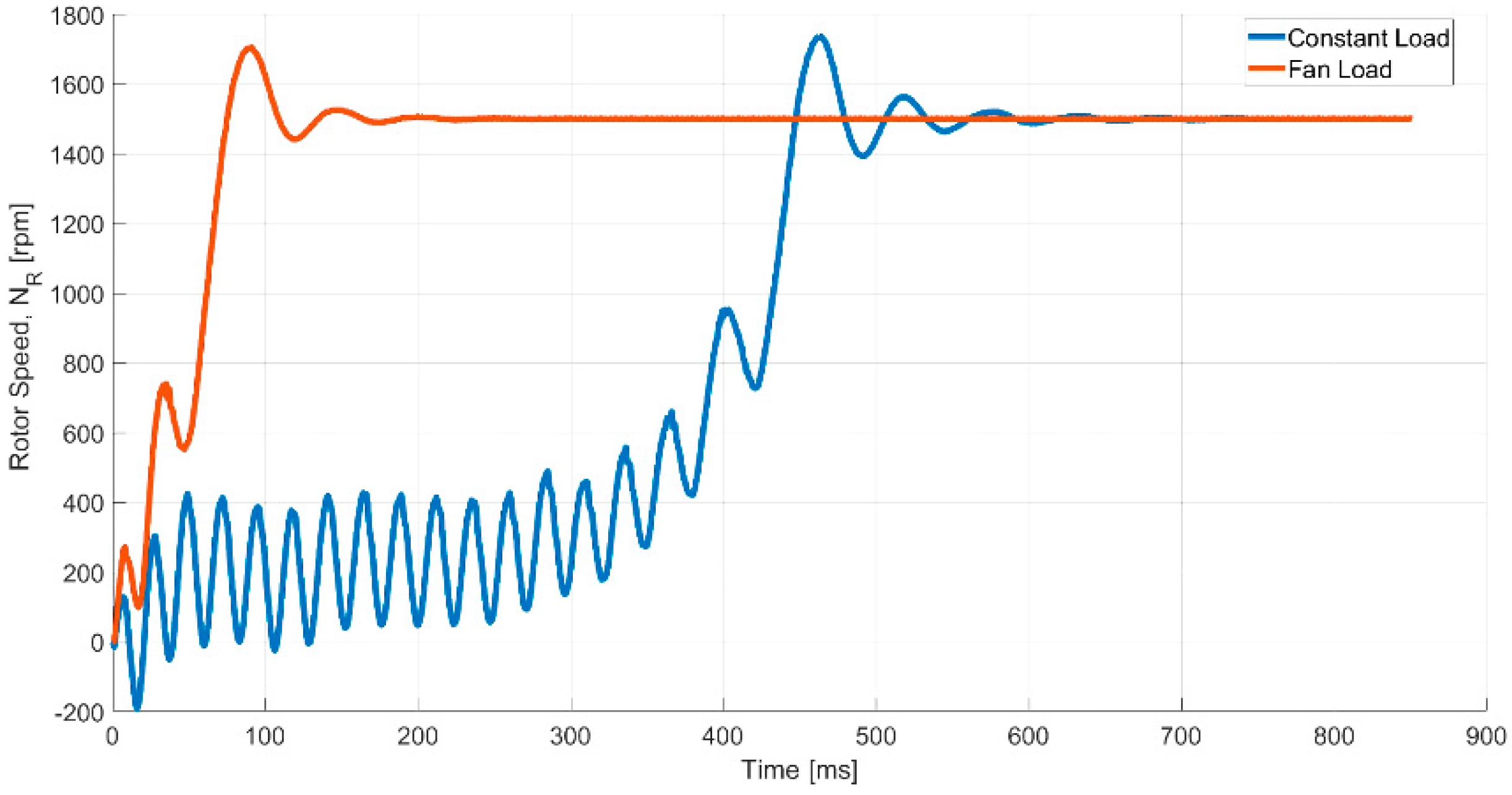
A superior performance can be obtained in the applications that have a square load profile, by using LM-PMSM, which offers a low starting performance under a constant load. The starting performance under the = 35 Nm constant and square load of the suggested model in Figure 16 was compared. As it can be understood from the figure, the motor with a low performance under a constant load can offer superior performance under a square load. It can be seen the suggested model in Figure 17 can be synchronized in 200 ms up to = 87.50 Nm (250% rated torque) loads successfully.
3. Conclusions
In this study, the rotor of a motor with a 5.5 kW power 4–pole IE2 efficiency class is remodeled using PM. Analytical methods and finite element analysis software environment were used in the modeling. As the stator section of the designed motor was obtained from an industrially marketed product, the rotor was designed using an accordant stator inner diameter and stack length values, thereby resulting in the designed motor operating in accordance with the other asynchronous motors with the same power. Works were carried out during the study for improving the torque ripples generated by the motor in LS-PMSM, which resulted in a significant decrease in the shaft torque quality. The best design parameters were determined via GA. An increase in the motor efficiency (of 6.28%) was obtained by redesigning the rotor of a motor in the moderate efficiency segment. A rotor design was suggested that can operate with IM, with the same power, as a result of using a compatible stator inner diameter and stack length. A new rotor topology with two different slot types as an upper and lower was suggested as a result of the design studies carried out. A satisfactory starting performance was obtained with the suggested topology. A new rotor design was introduced in the industrial pump and fan applications. In addition, a surface mount PM was used in the design of the suggested model, thereby eliminating problems such as the placement of the PM in the rotor core, which poses a difficult problem for motors with interior PMs.
Author Contributions
Formal analysis, B.Z. and M.E.; investigation, B.Z.; methodology, B.Z. and M.A.; resources, M.E.; supervision, M.A.; validation, B.Z.; writing (review and editing), B.Z.
Funding
This study was supported by the Gaziosmanpaşa University Scientific Research Projects Unit, project number 2017/90.
Conflicts of Interest
The authors declare no conflict of interest.
Nomenclature
| ,: Number of phase and pole |
| , : Output power and stator angular speed |
| , , , : Leakage reactances (the suffix “2” refers to the rotor) |
| , , , : Axis current (the suffix “2” refers to the rotor) |
| , : Magnetizing reactances |
| , : RMS of d- and q-axis currents |
| , , : Excitation voltage, excitation current, and phase voltage |
| , , : Cage torque, permanent magnet torque, and total electromagnetic torque |
| , : Asynchronous torque and synchronous torque |
| , , : Motor inertia, load torque, and square load profile coefficient |
| : Angle between EMF and terminal voltage |
| , , : Outer and inner diameter of stator, rotor diameter |
| , : Stack length and air gap |
| , : Air gap flux density and air gap power |
| , : Air gap flux and permanent magnet flux |
| , : Permanent magnet height and thickness (in calculations) |
| , : Magnet thickness and width (in optimization study) |
| , : Field strength of the air gap and field intensity of the permanent magnet |
| , : Permeability of air and relative recoil permeability |
| , , : Stator, rotor, and end ring current |
| , : Number of stator and rotor slots |
| , : Number of conductors in a slot and parallel paths in a stator winding |
| , , : Efficiency, power factor, and rated current |
| , : Cross-sectional area of rotor bar and end ring |
| , : Rotor and end ring current densities |
| , , : The rotor tooth width, rotor slot pitch, and the stacking factor |
| , , : Torque ripple, RMS of motor torque, and mean of motor torque |
| , , : Slot gap for upper slot, slot diameter, and rotor slot depth |
References
- Riba, J.R.; Torres, C.L.; Romeral, L.; Garcia, A. Rare-earth-free propulsion motors for electric vehicles: A technology review. Renew. Sustain. Energy Rev. 2016, 57, 367–379. [Google Scholar] [CrossRef] [Green Version]
- Koch, S.F.; Peter, M.; Fleischer, J. Lightweight Design and Manufacturing of Composites for High-performance Electric Motors. Procedia CIRP 2017, 66, 283–288. [Google Scholar] [CrossRef]
- Kampker, A.; Burggräf, P.; Nee, C. Costs, quality and scalability: Impact on the value chain of electric engine production. In Proceedings of the 2nd International Electric Drives Production Conference (EDPC), Nuremberg, Germany, 15–18 October 2012; pp. 1–6. [Google Scholar]
- De Almeida, A.T.; Ferreira, F.J.T.E.T.E.; Fong, J.A.C. Standards for Efficiency of Electric Motors. IEEE Ind. Appl. Mag. 2011, 17, 12–19. [Google Scholar] [CrossRef]
- De Almeida, A.T.; Ferreira, F.J.; Fong, J.A.C.; Brunner, C.U. Electric motor standards, ecodesign and global market transformation. In Proceedings of the IEEE/IAS Industrial and Commercial Power Systems Technical Conference, Clearwater Beach, FL, USA, 4–8 May 2008; pp. 1–9. [Google Scholar]
- Brunner, C.U.; Niederberger, A.A.; De Almeida, A.T.; De Keulenaer, H. Standards for efficient electric motor systems SEEEM building a worldwide community of practice. In Proceedings of the European Council for an Energy Efficient Economy (ECEEE) Summer Studies, La Colle sur Loup, France, 4–9 June 2007; pp. 1443–1455. [Google Scholar]
- Isfahani, A.H.; Zadeh, S.V. Line start permanent magnet synchronous motors: Challenges and opportunities. Energy 2009, 34, 1755–1763. [Google Scholar] [CrossRef]
- Behbahanifard, H.; Sadoughi, A. Line Start Permanent Magnet Synchronous Motor Performance and Design; a Review. J. World Electr. Eng. Tech. 2015, 4, 58–66. [Google Scholar]
- Honsinger, V. Permanent Magnet Machines: Asychronous Operation. IEEE Trans. Power Appar. Syst. 1980, PAS-99, 1503–1509. [Google Scholar] [CrossRef]
- Stoia, D.; Chirila, O.; Cernat, M.; Hameyer, K.; Ban, D. The Behaviour of The LSPMSM in Asynchronous Operation. In Proceedings of the 14th International Power Electronics and Motion Control Conference (EPE-PEMC 2010), Ohrid, Macedonia, 6–8 September 2010; pp. T4-45–T4-50. [Google Scholar]
- Miller, T.J.E. Synchronization of Line-Start Permanent-Magnet AC Motors. IEEE Trans. Power Appar. Syst. 1984, PAS-103, 1822–1828. [Google Scholar] [CrossRef]
- Soulard, J.; Nee, H.P. Study of the synchronization of line-start permanent magnet synchronous motors. In Proceedings of the Thirty-Fifth IAS Annual Meeting and World Conference on Industrial Applications of Electrical Energy, Rome, Italy, 8–12 October 2000; Volume 1, pp. 424–431. [Google Scholar]
- Isfahani, A.H.; Zadeh, S.V.; Rahman, M.A. Evaluation of Synchronization Capability in Line Start Permanent Magnet Synchronous Motors. In Proceedings of the IEEE International Electric Machines & Drives Conference (IEMDC), Niagara Falls, ON, Canada, 15–18 May 2011; pp. 1346–1350. [Google Scholar]
- Rabbi, S.F.; Rahman, M.A. Determination of the synchronization criteria of line start IPM motors. In Proceedings of the International Electric Machines & Drives Conference, Chicago, IL, USA, 12–15 May 2013; pp. 1218–1224. [Google Scholar]
- Nedelcu, S.; Tudorache, T.; Ghita, C. Influence of design parameters on a line start permanent magnet machine characteristics. In Proceedings of the 13th International Conference on Optimization of Electrical and Electronic Equipment (OPTIM), Brasov, Romania, 24–26 May 2012; pp. 565–571. [Google Scholar]
- Yang, Y.; Wang, X.; Zhang, R.; Ding, T.; Tang, R. The optimization of pole arc coefficient to reduce cogging torque in surface-mounted permanent magnet motors. IEEE Trans. Magn. 2006, 42, 1135–1138. [Google Scholar] [CrossRef]
- Kang, G.H.; Hur, J.; Nam, H.; Hong, J.P.; Kim, G.T. Analysis of irreversible magnet demagnetization in line-start motors based on the finite-element method. IEEE Trans. Magn. 2003, 39, 1488–1491. [Google Scholar] [CrossRef]
- Liu, X.; Lin, Q.; Fu, W. Optimal Design of Permanent Magnet Arrangement in Synchronous Motors. Energies 2017, 10, 1700. [Google Scholar] [CrossRef]
- Rabbi, S.F.; Rahman, M.A. Critical Criteria for Successful Synchronization of Line-Start IPM Motors. IEEE J. Emerg. Sel. Top. Power Electron. 2014, 2, 348–358. [Google Scholar] [CrossRef]
- Boldea, I.; Nasar, S.A. The Induction Machines Design Handbook, 2nd ed.; CRC Press/Taylor & Francis: Boca Raton, FL, USA, 2010; ISBN 978-1-4200-6668-5. [Google Scholar]
- Elistratova, V. Optimal Design of Line-Start Permanent Magnet Synchronous Motors of High Effiency. Ph.D. Thesis, Ecole Centrale de Lille, Villeneuve-d’Ascq, France, 2015. [Google Scholar]
- Dosiek, L.; Pillay, P. Cogging Torque Reduction in Permanent Magnet Machines. In Proceedings of the IEEE Industry Applications Conference Forty-First IAS Annual Meeting, Tampa, FL, USA, 8–12 October 2006; pp. 44–49. [Google Scholar]
- Jędryczka, C.; Knypiński, Ł.; Demenko, A.; Sykulski, J.K. Methodology for Cage Shape Optimization of a Permanent Magnet Synchronous Motor Under Line Start Conditions. IEEE Trans. Magn. 2018, 54, 1–4. [Google Scholar] [CrossRef] [Green Version]
- Pyrhonen, J.; Jokinen, T.; Hrabovcova, V. Design of Rotating Electrical Machines, 2nd ed.; Wiley: Chichester, UK, 2014; ISBN 978-1-118-58157-5. [Google Scholar]
- Kumar, A.; Srivastava, A. Performance Comparison of Two Different Rotor Topologies of Line Start Permanent Magnet Synchronous Motors. Int. J. Res. Appl. Sci. Eng. Technol. 2017, 5, 2313–2318. [Google Scholar]
- Ugale, R.T.; Chaudhari, B.N.; Pramanik, A. Overview of research evolution in the field of line start permanent magnet synchronous motors. IET Electr. Power Appl. 2014, 8, 141–154. [Google Scholar] [CrossRef]
- Dinh, B.M. Optimal Rotor Design of Line Start Permanent Magnet Synchronous Motor by Genetic Algorithm. Adv. Sci. Technol. Eng. Syst. J. 2017, 2, 1181–1187. [Google Scholar] [CrossRef] [Green Version]
- Ding, T.; Takorabet, N.; Sargos, F.; Wang, X. Design and Analysis of Different Line-Start PM Synchronous Motors for Oil-Pump Applications. IEEE Trans. Magn. 2009, 45, 1816–1819. [Google Scholar] [CrossRef]
- Huang, P.W.; Mao, S.H.; Tsai, M.C.; Liu, C.T. Investigation of line start permanent magnet synchronous motors with interior-magnet rotors and surface-magnet rotors. In Proceedings of the International Conference on Electrical Machines and Systems, Wuhan, China, 17–20 October 2008; pp. 2888–2893. [Google Scholar]
- XuXiaozhuo, X. Performance of Line-start Permanent Magnet Synchronous Motor with Novel Rotor Structure. Int. J. Digit. Content Technol. Its Appl. 2013, 7, 1217–1225. [Google Scholar] [CrossRef]
- Bianchi, N.; Bolognani, S. Design techniques for reducing the cogging torque in surface-mounted PM motors. In Proceedings of the Thirty-Fifth IAS Annual Meeting and World Conference on Industrial Applications of Electrical Energy (Cat. No.00CH37129), Rome, Italy, 8–12 October 2000; pp. 179–185. [Google Scholar]
- Ortega, A.J.P.; Xu, L. Analytical Prediction of Torque Ripple in Surface-Mounted Permanent Magnet Motors Due to Manufacturing Variations. IEEE Trans. Energy Convers. 2016, 31, 1634–1644. [Google Scholar] [CrossRef]
- Garner, K.; Grobler, A.J. Rotor Design of a Retrofit Line Start Permanent Magnet Synchronous Motor. In Proceedings of the 23rd Southern African Universities Power Engineering Conference (SAUPEC), Johannesburg, African, 28–30 January 2015; pp. 221–226. [Google Scholar]
- National Electrical Manufacturers Association. Motors and Generators; MG1-1993; NEMA: Washington, DC, USA, 1993. [Google Scholar]
- Cetin, E.; Daldaban, F. Analyzing the Profile Effects of the Various Magnet Shapes in Axial Flux PM Motors by Means of 3D-FEA. Electronics 2018, 7, 13. [Google Scholar] [CrossRef]
- Islam, R.; Ortega, A.P. Practical aspects of implementing skew angle to reduce cogging torque for the mass-production of permanent magnet synchronous motors. In Proceedings of the 20th International Conference on Electrical Machines and Systems (ICEMS), Sydney, NSW, Australia, 11–14 August 2017; pp. 1–5. [Google Scholar]
- Sheth, N.K.; Sekharbabu, A.R.C.; Rajagopal, K.R. Torque ripple minimization in a doubly salient permanent magnet motors by skewing the rotor teeth. J. Magn. Magn. Mater. 2006, 304, e371–e373. [Google Scholar] [CrossRef]
- Kim, B.; Kim, D.; Know, B.; Lipo, T.A. Optimal Skew Angle for Improving of Start-Up Performance of a Single-Phase Line-Start Permanent Magnet Motor. In Proceedings of the IEEE Industry Applications Society Annual Meeting, Edmonton, AB, Canada, 5–9 October 2008; pp. 1–6. [Google Scholar]
- Hsiao, C.-Y.; Yeh, S.-N.; Hwang, J.-C. A Novel Cogging Torque Simulation Method for Permanent-Magnet Synchronous Machines. Energies 2011, 4, 2166–2179. [Google Scholar] [CrossRef] [Green Version]
- Zhu, Z.Q.; Howe, D. Influence of design parameters on cogging torque in permanent magnet machines. IEEE Trans. Energy Convers. 2000, 15, 407–412. [Google Scholar] [CrossRef] [Green Version]
Figure 1.
Torque components of the line start permanent magnet synchronous motors (LS-PMSM).

Figure 2.
Optimal LS-PMSM design algorithm.

Figure 3.
Suggested rotor design.

Figure 4.
= 35 Nm; = 1 p.u. Starting process of the analytical model: (a) speed characteristic and (b) torque characteristic.
Figure 4.
= 35 Nm; = 1 p.u. Starting process of the analytical model: (a) speed characteristic and (b) torque characteristic.

Figure 5.
Design optimization.

Figure 6.
Cost function.

Figure 7.
Distribution of genetic algorithm (GA) analysis parameters according to the number of evolutions.
Figure 7.
Distribution of genetic algorithm (GA) analysis parameters according to the number of evolutions.

Figure 8.
Ripple and efficiency obtained for different stator skew angles.

Figure 9.
Motor synchronization performance for different stator skew angles.

Figure 10.
The cogging torque generated during a 30° rotation of the motor for and skew angles.

Figure 11.
Change in electromagnetic torque subject to rotor revolution generated by the motor for and angles.
Figure 11.
Change in electromagnetic torque subject to rotor revolution generated by the motor for and angles.

Figure 12.
Starting performance for the suggested model with skewed stator under different motor loads.
Figure 12.
Starting performance for the suggested model with skewed stator under different motor loads.

Figure 13.
Current and efficiency values obtained from the motor subject to load torque.

Figure 14.
The meshed model of the LS-PMSM with suggested rotor design: (a) rotor and (b) stator.

Figure 15.
Field reports of the LS-PMSM with suggested rotor design: (a) flux distributions at the stator and rotor cores in steady state operation and (b) vector distribution.
Figure 15.
Field reports of the LS-PMSM with suggested rotor design: (a) flux distributions at the stator and rotor cores in steady state operation and (b) vector distribution.

Figure 16.
Starting performance under = 35 Nm constant and square load of the suggested model.

Figure 17.
Starting performance under different square loads of the suggested model.


Table 1.
Main dimensions of the reference motor.
| Frame | ||||
|---|---|---|---|---|
| 132 s4 | 5.5 kW | 125 mm | 200 mm | 125 mm |
Table 2.
Stator design details.
| Winding Layer | Winding Type | Conductor per Slots | Coil Pitch | Number of Strands | Wire Size | Steel Type | Number of Slots |
|---|---|---|---|---|---|---|---|
| 2 | Whole-Coiled | 28 | 7 | 3 | 0.9116 | M330 50A | 36 |
Table 3.
Label information for the reference motor.
| Output Power | Rated Current | R.P.M. min−1 | Power Factor | Eff. % | Starting Current | Rated Torque | Starting Torque | Weight |
|---|---|---|---|---|---|---|---|---|
| 5.5 kW | 11.8 A | 1440 | 0.83 | 85 | 7 p.u. | 36.5 Nm | 2.3 p.u. | 63 kg |
Table 4.
Design parameters used for the optimization of the model.
| Design Parameters | Initial Value | Min. | Max. |
|---|---|---|---|
| 41° | 36° | 42° | |
| 4.7 mm | 4 mm | 5 mm | |
| 1.5 mm | 1 mm | 2 mm | |
| 9 mm | 8 mm | 9 mm | |
| 0.5 mm | 0.25 mm | 1.2 mm | |
| 61.5 | 61 mm | 62 mm |
Table 5.
Change in design parameters and motor efficiency after genetic algorithm (GA) optimization.
Table 5.
Change in design parameters and motor efficiency after genetic algorithm (GA) optimization.
| Design Parameters | Before GA Optimization | After GA Optimization |
|---|---|---|
| 41° | 40.5° | |
| 4.7 mm | 4.48 mm | |
| 1.5 mm | 1.79 mm | |
| 9 mm | 8.5 mm | |
| 0.5 mm | 1 mm | |
| 61.5 | 61.30 mm | |
| 91.14% | 92% | |
| 19.98 (SI) | 7.09 (SI) | |
| 9.6 A | 9.26 A |
© 2018 by the authors. Licensee MDPI, Basel, Switzerland. This article is an open access article distributed under the terms and conditions of the Creative Commons Attribution (CC BY) license (http://creativecommons.org/licenses/by/4.0/).
Share and Cite
MDPI and ACS Style
Zöhra, B.; Akar, M.; Eker, M. Design of A Novel Line Start Synchronous Motor Rotor. Electronics 2019, 8, 25. https://doi.org/10.3390/electronics8010025
AMA Style
Zöhra B, Akar M, Eker M. Design of A Novel Line Start Synchronous Motor Rotor. Electronics. 2019; 8(1):25. https://doi.org/10.3390/electronics8010025
Chicago/Turabian StyleZöhra, Berkan, Mehmet Akar, and Mustafa Eker. 2019. "Design of A Novel Line Start Synchronous Motor Rotor" Electronics 8, no. 1: 25. https://doi.org/10.3390/electronics8010025
Note that from the first issue of 2016, this journal uses article numbers instead of page numbers. See further details here.