Design and Optimization of Supercapacitor Hybrid Architecture for Power Supply-Connected Batteries Lifetime Enhancement †


1
Sindoh Co., Ltd., Seoul 04797, Korea
2
Department of Smart Systems Software, Soongsil University, Seoul 06978, Korea
3
Department of Control and Computer Engineering (DAUIN), Politecnico di Torino, 10129 Torino, Italy
4
School of Electrical Engineering, University of Ulsan, Ulsan 44610, Korea
*
Authors to whom correspondence should be addressed.
†
This paper is an extended version of our paper published in IEEE/ACM The International Symposium on Low Power Electronics and Design (ISLPED), 2014.
Electronics 2019, 8(1), 41; https://doi.org/10.3390/electronics8010041
Submission received: 3 October 2018
/
Revised: 3 December 2018
/
Accepted: 21 December 2018
/
Published: 1 January 2019
(This article belongs to the Special Issue Hardware and Architecture)
Abstract
:AC power adapters for battery-operated systems, such as smartphones and notebook computers, not only supply run-time power to operate the devices but also charge the built-in batteries. The capacity of the adapter is optimized for the average power demand rather than the maximum power demand to reduce the size and weight of the adapter. Such a reduced capacity adapter may cause the battery to age even when the device is operated with the power adapter while under higher power demand, which is different from the expectation of most users. A recent study proposed a supercapacitor assist architecture to reduce the battery aging when the battery is powered by the adapter. However, the previous work only shows the potential of the architecture. In this work, we propose a design methodology to find the optimal setup for the supercapacitor hybrid architecture considering supercapacitor array structure and power conversion efficiency. The results show that a supercapacitor having 17.5 mF capacity and 20 V withstand voltage is enough to supply the deficient energy of a reduced capacity power adapter.
1. Introduction
The size and weight of portable devices are continuously reduced, and the adapter shipped by the manufacturers are reduced in size as well. Since many users usually bear the adapter to avoid the unexpected depletion of the battery, it is quite natural that users want to carry a light-weight, small-form factor power adapter. In these days, manufacturers also aim at development of a light-weight, small-form factor power adapters due to the cost. They provide a smaller capacity power adapter instead of a full power adapter that can support the worst-case power demand to reduce the size, weight, and cost. It seems a reasonable idea where there is a battery as a temporal energy buffer to deal with a short period of excessive power demands. Table 1 presents the specified power consumption of two laptop computers by components and the capacity of their power supplies. In case of the Lenovo notebook, the specified power demand exceeds the power provided by the adapter by 4 W, in case of the Apple notebook, the gap is even bigger and comes to 14 W.
The users usually expect that the reduced adapter would not affect the built-in battery lifetime of the laptop. However, a recent study [6] shows that the reduced capacity adapter may incur the battery aging even though the adapter is supplying the laptop. With higher power demands, the adapter cannot supply this demand fully, hence the deficient power is drawn from the battery. The aging caused by the deficient power may be significant and the battery lifetime might be reduced to 23% of the shelf lifetime when the battery is connected to the reduced capacity adapter under normal usage conditions [6]. Note that shelf lifetime is the time it takes until the capacitance of a stored and unused battery has faded to 80% of its initial capacity.
A hybrid energy storage systems consisting of supercapacitors and Li-ion batteries have been studied to compensate the disadvantages of Li-Ion batteries [7,8,9]. On the other hand, the supercapacitor and Li-ion battery hybrid system for electrical vehicles (EV) is intensively studied [10,11]. The EVs changes its state between the charging and discharging battery frequently. The hybrid system enhances the lifetime of battery by reducing charging and discharging current. It also effectively buffers the generated power fluctuation from a photovoltaic cell or wind turbine [12,13]. A temporal buffer based on the supercapacitor hybrid architecture enhance battery lifetime of electric vehicles or mobile systems by cooling the battery down [14]. Krishna et al studied battery and the supercapacitor hybrid system for real-time sporadic workloads [15]. However, the previous works do not target for the reduced capacity adapter and built-in batteries. The load variation not only affect the system efficiency but also its lifetime. The lifetime of the batteries related to its initial state is usually expressed by the State of Health (SOH) (The SOH describes the condition of the battery related to its specification. The ratio of remaining lifetime to expected lifetime of an unused battery is used as a measure of SOH.). A capacity fade (SOH degradation) phenomena is well-known aspect of the battery long-term behavior for various kind of batteries. It is the result of the damages in the active materials of the battery during usage of battery. The operating conditions determine the speed of degradation, and the capacity fade of Li-ion batteries is often modeled by an Arrhenius type of equation as a function of discharge condition statistics.
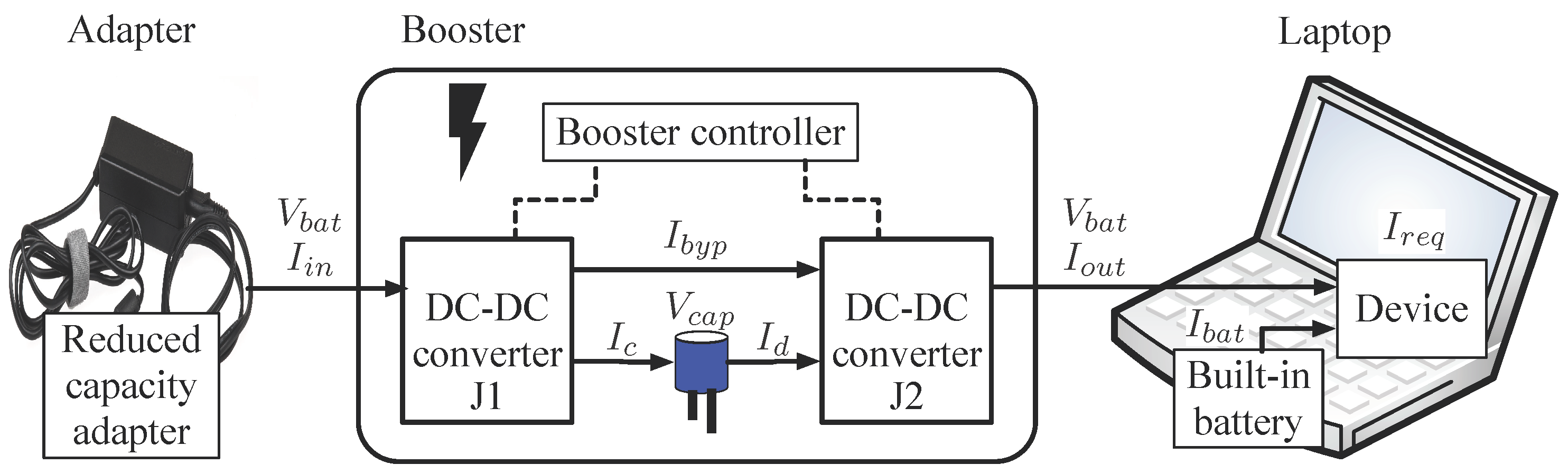
The recent study [6] uses a hybrid architecture shown in Figure 1 as a solution to battery aging for power adapter connected batteries. It also considers the fact that the terminal voltage of the supercapacitor varies linearly with its state of charge (SOC) (The SOC is the ratio of available charge in the battery to the maximum available charge of a recharged battery.). The large swing of the supercapacitor terminal voltage results in significant variation of power converter efficiency because its conversion efficiency is affected by the input voltage, output voltage and input current of the power converter [16]. However, while the previous work shows the potential and feasibility of the hybrid architecture, it does not optimize the design of the hybrid architecture. In this work, we propose a design methodology to find the optimal setup of the supercapacitor hybrid architecture in order to enhance the battery lifetime and show the optimization results according to the proposed methodology.
The optimal setup of hybrid architecture change if the deficient power and the daily usage pattern changes. Therefore, we first analyze the deficient energy from the built-in battery current profile, which is measured on a commercial laptop computer running benchmarking programs [6]. Second, we perform a circuit-level simulation with a supercapacitor charge buffer between the power adapter and the device that mitigates the battery aging in battery-connected condition while changing its capacitance. Then, we estimate the battery aging from the statistical data and the SOH degradation model. We convert the time series of the battery current profiles to statistical data because the existing SOH degradation model only considers periodic charging and discharging sequences. Finally, we perform a systematic design space exploration to maximally enhance the battery lifetime with the minimum cost considering: (i) supercapacitor array setup with standard unit cells; and (ii) Voltage swing and capacity of supercapacitor setup and converter efficiency. We also propose an algorithmic solution to find the optimal supercapacitor array with given battery and load conditions. The remainder of this paper is organized as follows. We give an overview of related work in Section 2. Next, we describe our design methodology in Section 3. We derive the optimal setup of hybrid architecture according to the proposed methodology and discuss the lifetime comparison and its cost in Section 4. The paper concludes with Section 5, where we discuss the implications of our work.
2. Related Work
2.1. Battery Aging
Battery aging has been studied extensively because it reduces the operation time of portable devices powered by batteries. The battery aging can be classified into two categories by its origin. The first category is a calendar aging which degrades the battery life when the battery is not used. The calendar aging depends on the battery storage conditions such as the SOC of the battery and the environmental temperature [17]. The other source of battery aging is the amount of charging and discharging current when the battery is used. The impact of discharge C-rates on battery aging has been studied in [18]. The average SOC, SOC swing and temperature can be used to calculate the amount of aging instead of the C-rate [19].
The battery aging model based on the SOC swing and average SOC has been proposed to predict the battery degradation [19]. The parameters of the battery aging model is extracted by fitting empirical data [19,20]. In this paper, we adopt this model to estimate the battery degradation due to aging. For the sake of completion, we will explain this model and the way to adopt it. The life parameter L is used to denote the lifetime of battery. If the battery is new, L is 0 while means the battery has no capacity left. We calculate which indicates the life parameter after m-th time interval. is incremented by either or depending on the battery usage (idle or active). The time interval denotes one cycle time of discharging and charging in seconds, in thus the length of varies time to time. From the definition, is calculated as below:
There is no SOC swing when the battery is idle [21], thus, only the calendar aging needs to be considered. When the battery is idle, the life parameter is calculated by:
where and are the total amount of idle time and the total expected shelf life in seconds to 80% capacity at 25 C and 50% SOC, respectively. Note that we assume as 15 years. is the battery temperature and is the reference battery temperature. The while using the battery within is given by:
where , , , and are a coefficient of throughput, an exponent for depth of discharge (DOD) (The DOD is an alternative measure of the battery SOC, where a DOD of 1 denotes an empty battery and 0 a full battery.), a coefficient for average SOC and a doubling of decay rate for each 10 C rise in temperature [19] and time in seconds of a cycle, respectively. The mean SOC () and a normalized deviation from average SOC () given by:
The effective number of throughput cycles N deals with microcycles:
where is the nominal charge capacity of the battery. We use the same parameters as presented in [19], which are derived for the A123 ANR26650M1A Li-ion battery cell such that for DOD 0.35 to 0.95, , and . is assumed to be C, and is set to C.
2.2. Supercapacitor–Battery Hybrid Architecture
Electric double layer capacitors, more commonly known as supercapacitors, have a superior cycle efficiency defined as the ratio of the energy output to energy input, which reaches almost 100%. Moreover, supercapacitors have a high charge-discharge cycle frequency and no aging effects [7] while they have some disadvantages such as having a relatively smaller capacity and higher cost compared to Li-ion batteries. Since the Li-ion batteries are severely aged during they are active as shown in Section 2.1, a supercapacitor suits well as a small charge buffer to mitigate load current fluctuations.
However, the terminal voltage level of the supercapacitor (or any kinds of capacitor) depends on its state of charge and capacitance. The variations of its voltage level require a DC–DC converter to supply constant voltage level power. The efficiency of the DC–DC converter depends on the voltage level difference between the input power source and output power. The variations of the supercapacitor level become smaller as we increase its capacitance, which increases its capital cost. The withstand voltage level of supercapacitor also increases its capital cost. Therefore, we aim to both minimize the capacitance and withstand voltage of the target buffer supercapacitor in this work.
3. Booster Design for a Reduced Capacity Adapter
The reduced capacity adapter incurs additional battery aging when the laptop is supplied through it. Of course, the built-in battery is aging when the laptop is operated by it without an external power adapter, but this is unavoidable. Hence, we focus on the booster that eliminates the effect of the reduced capacity adapter when the laptop is connected to the wall power through the adapter. A supercapacitor–battery hybrid architecture is proposed to mitigate the battery aging caused by the reduced capacity adapter, but the optimal configuration of the hybrid architecture is not explored. Therefore, we propose a methodology to design a booster with optimal configuration of the hybrid architecture.
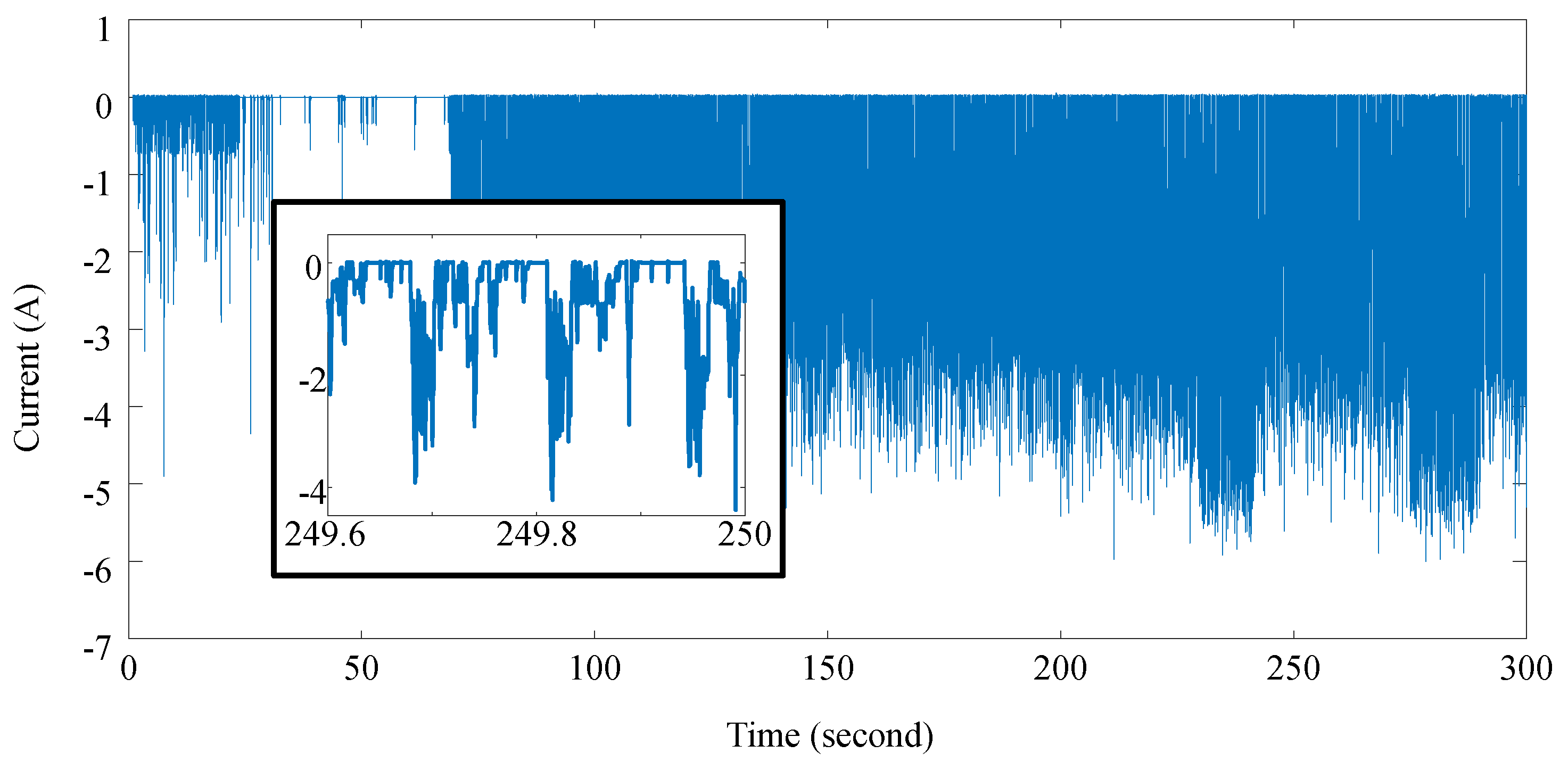
Figure 2 shows the design methodology of the optimal booster for a reduced capacity adapter. The deficient power causes the additional battery aging which we target to mitigate. Hence, the first step is measuring the deficient current profile which causes additional battery aging, as shown in Figure 3. Second step is histogram analysis of the deficient energy during the measurement. Knowing the amount of deficient energy is a key factor for optimal design because is a function of and . We need to calculate the amount of deficient energy from the measured current profile. If the adapter is connected, the battery is fully charged most of time because the reduced capacity adapter is able to provide the average power demand even though it fails to meet the maximum power requirement [6]. Hence, we need to consider the situation that discharging starts from the fully charged battery, which reduces the burden of calculation. The discharging begins when the power demand exceeds the adapter capacity and lasts until the power demand is less than the adapter capacity. We calculate the amount of deficient energy by integrating the discharge current during a discharging cycle. Then, we decide the upper bound of deficient energy to be compensated. This upper bound determines the trade-off between the battery lifetime and the cost of hybrid architecture. If we eliminate all the energy peaks by the supercapacitor charge buffer, there is no battery aging due to the reduced capacity adapter.
Next, we determine the optimal specification of a supercapacitor charge buffer by exploring design space using a unit capacitor array. Note that the design space stands for potential design candidates for optimal design. In this work, the design space includes the lower and the upper bounds of supercapacitor voltage and the capacitance of the supercapacitor. The input voltage of the charging DC–DC converter, J1 in Figure 1, is set as the adapter output voltage. The charging DC–DC converter charges the unit capacitor array until the terminal voltage of the unit capacitor array reaches the upper bound of swing voltage. The input voltage of the discharging DC–DC converter, J2 in Figure 1, is the terminal voltage of the unit capacitor array. The output voltage of the discharging DC–DC converter is set as the typical nominal voltage of the built-in battery when it is fully charged, respectively. We use the most frequent peak current of workload as the constant output current of DC–DC converter. The variation of the terminal voltage of the unit capacitor array is inevitable due to the characteristics of the supercapacitor. Since the efficiency of DC–DC converter is related to the difference of input voltage and output voltage, the lower and upper bound of the supercapacitor voltage level strongly affect DC–DC converter power efficiency [22]. To make the DC–DC converter have the highest efficiency, it is necessary to meet the input voltage level and output voltage level. Hence, there could be two methods to increase the withdrawable energy from the supercapacitor: (a) Increasing voltage swing to make supercapacitor store much more energy; (b) Decreasing voltage swing to meet the sweet spot of the DC–DC converter. To effectively search the design space, we first increase the lower bound level of the supercapacitor voltage to change voltage swing while we freeze the upper bound level of the voltage. Then we confirm that increasing voltage swing is a dominant factor to increase the withdrawable energy from the supercapacitor. So, we set the lower bound level of the supercapacitor voltage as the typical required minimal voltage level of the DC–DC converter. We also set the limit of upper bound voltage level as the typical maximum withstand voltage level of the DC–DC converter.
Next, we search the design space while we increase the upper bound of the supercapacitor voltage level. Let us assume that we have a parallel and series connected unit capacitor array which consists of unit capacitors, which have C capacity and V withstand voltage. P is the number of unit capacitors connected in parallel and S is the number of unit capacitors connected in series, respectively. Then, the array of unit capacitor has capacity and withstanding voltage. For example, the unit capacitor array has 10 V withstand voltage and 5 mF capacity if we make a unit capacitor array with 1 mF and 1 V unit capacitors. We assume that the supercapacitor is always fully charged before the laptop runs heavy workloads because the adapter is always supplying power for the laptop even when the laptop is idle. We repeatedly increase P and S and calculate the possible withdrawable energy from the unit capacitor until the unit capacitor array is able to supply equal to or greater than the required amount of energy. The withdrawable energy is calculated by integrating discharging power over time while considering DC–DC conversion efficiency. Finally, the optimal hybrid architecture is derived by selecting a unit capacitor array, which has the least unit capacitors (total unit capacitor in the unit capacitor array). We verify the configuration by comparing the life parameter using Equation (1).
4. Optimization Result
Deficient power incurs additional battery aging and varies according to the usage pattern. Therefore, the configuration of hybrid architecture such as capacitance of buffer capacitor, the lower and upper bounds of the swing voltage level should be changed to consider the usage pattern change. Finding the optimal configuration would be a burden if we do not rely on the systematic approach. We propose a design methodology to find the optimal hybrid architecture. In this section, we show the optimization results by applying the proposed methodology.
We use a Lenovo T530-2359-A44 laptop with a 90-W reduced power adapter to run the online 3D based city planning simulation video game Simcity (2013) from EA Games as a heavy workload. We measure the current and voltage profile of the laptop battery with the laptop connected to the adapter while running Simcity (2013), as shown in Figure 3. The battery suffers from discharging current which is presented as a negative current. The enlarged figure shows that the battery is discharged in a short period. We exploit the one cycle time when to charge supercapacitor buffer. The charged supercapacitor buffer helps battery by discharging when .
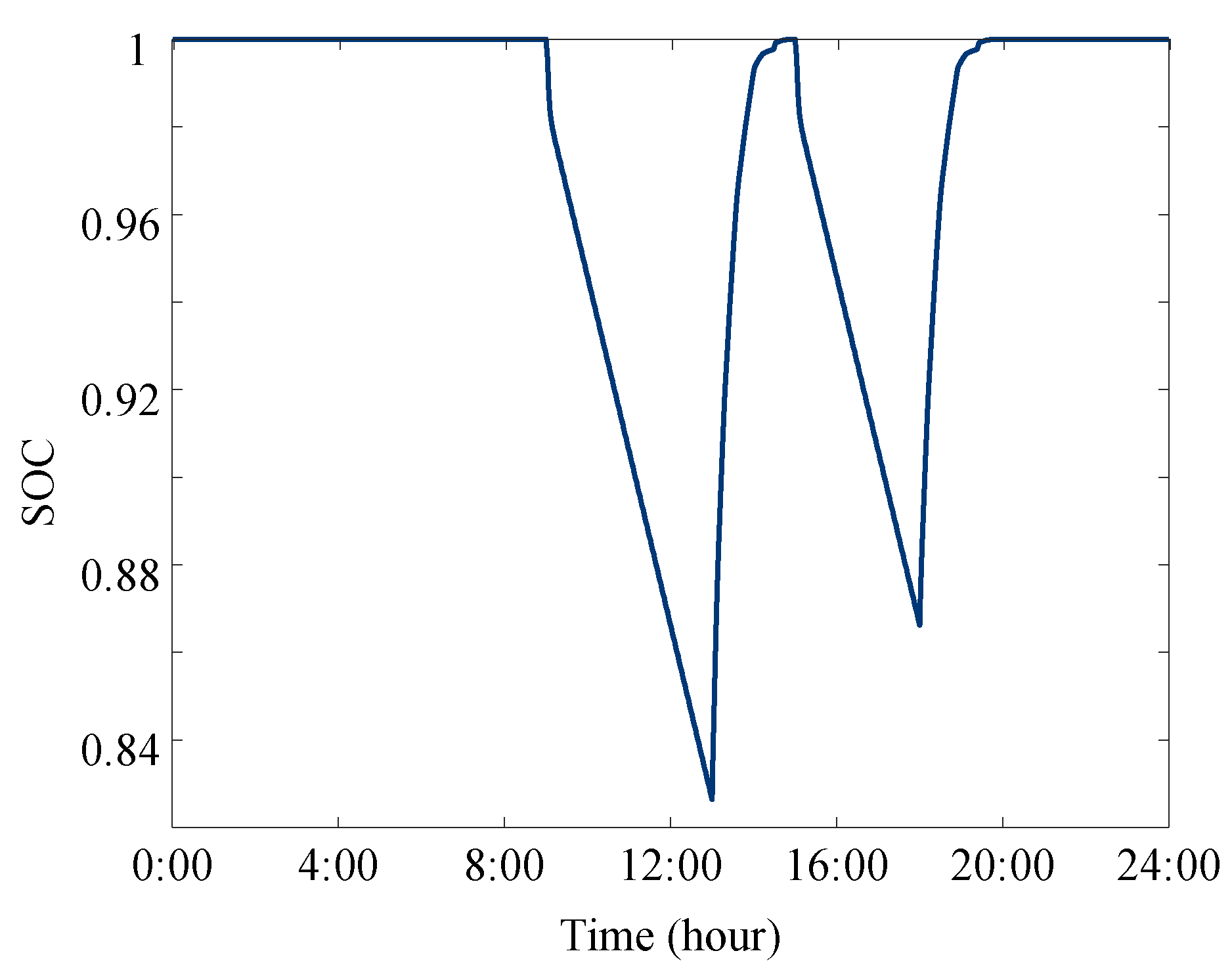
Because the lifetime of a battery is usually more than a year, it is not practical to measure the battery discharging current during the whole lifetime. Therefore, we design an exemplary daily usage profile from the measurement with a heavy workload and use it to estimate the battery lifetime. The daily usage profile is designed under the assumption that the user will run the same workload every day. We concatenate the heavy workload profile, as shown in Figure 3, instead of running the heavy workload for a whole day to simulate the laptop usage during a day. We depict the daily usage profile as shown in Figure 4.
Next, we analyze the amount of deficient energy due to the reduced capacity adapter from the workload profile. Figure 5 shows the histogram of deficient energy peaks while running the heavy workload. Note that the deficient energy peak is calculated by integrating the discharge current over time during a discharging cycle, which can be different time to time as presented in Section 3. The y-axis of the histogram is a log scale, in thus the histogram shows that most of the deficient energy peaks are less than 1 J. We confirm this by using the cumulative ratio of deficient energy peaks which is presented as the red line in Figure 5.
To decide the upper bound of deficient energy to be compensated is the following step. We decide the upper bound as 2.3 J which covers 99.9% of the deficient energy. According to the proposed methodology, we explore the design space of supercapacitor hybrid architecture using a unit capacitor array. We set the lower of the unit capacitor array voltage level as 4 V (the minimum required voltage level of the DC–DC converter), the upper bound of the unit capacitor array voltage level as 20 V (the maximum withstand voltage level of the DC–DC converter), the output voltage of a DC–DC converter as 12 V (the typical nominal voltage of the built-in battery), and the output current of the DC–DC converter as 4 A (the most frequent peak current of workload), respectively. The other parameters of DC–DC converter come from [22]. We also explore the output current of the DC–DC converter, but the difference of effect on life parameter is negligible. For a unit capacitor array, we set V as 1 V and C as 10 mF and simulate with 100 us time resolution. We repeatedly calculate the possible energy amount from the unit capacitor array by increasing S from 4 to 20 and P from 1 to 100, respectively.
We justify the setting of the lower bound of unit capacitor array as the minimum required voltage level of the DC–DC converter before the design space exploration. Figure 6 shows the relation among the lower bound of the unit capacitor array voltage level, the upper bound of the unit capacitor array voltage level, and the required capacitance. We explore the lower and the upper bound of the unit capacitor array voltage level from 4 V to 14 V and from 11 V to 20 V, respectively. The increase of required capacitance implies the increase of cost and volume, so it is better to reduce the required capacitance by lowering the lower bound. Therefore, we do not need to search the lower bound of unit capacitor array during design space exploration.
Figure 7 shows the results of design space exploration considering DC–DC converter efficiency. The surface represents the usable energy from the unit capacitor array, which consists of unit capacitors. The red line indicates the upper bound of deficient energy to be compensated which is 2.3 J under the assumed usage profile. Among the possible candidate of {P, S} set located on and above the red line, we choose {35, 20} which has the minimum number of unit capacitor. This configuration is equivalent to a supercapacitor having 17.5 mF capacity and 20 V withstand voltage.
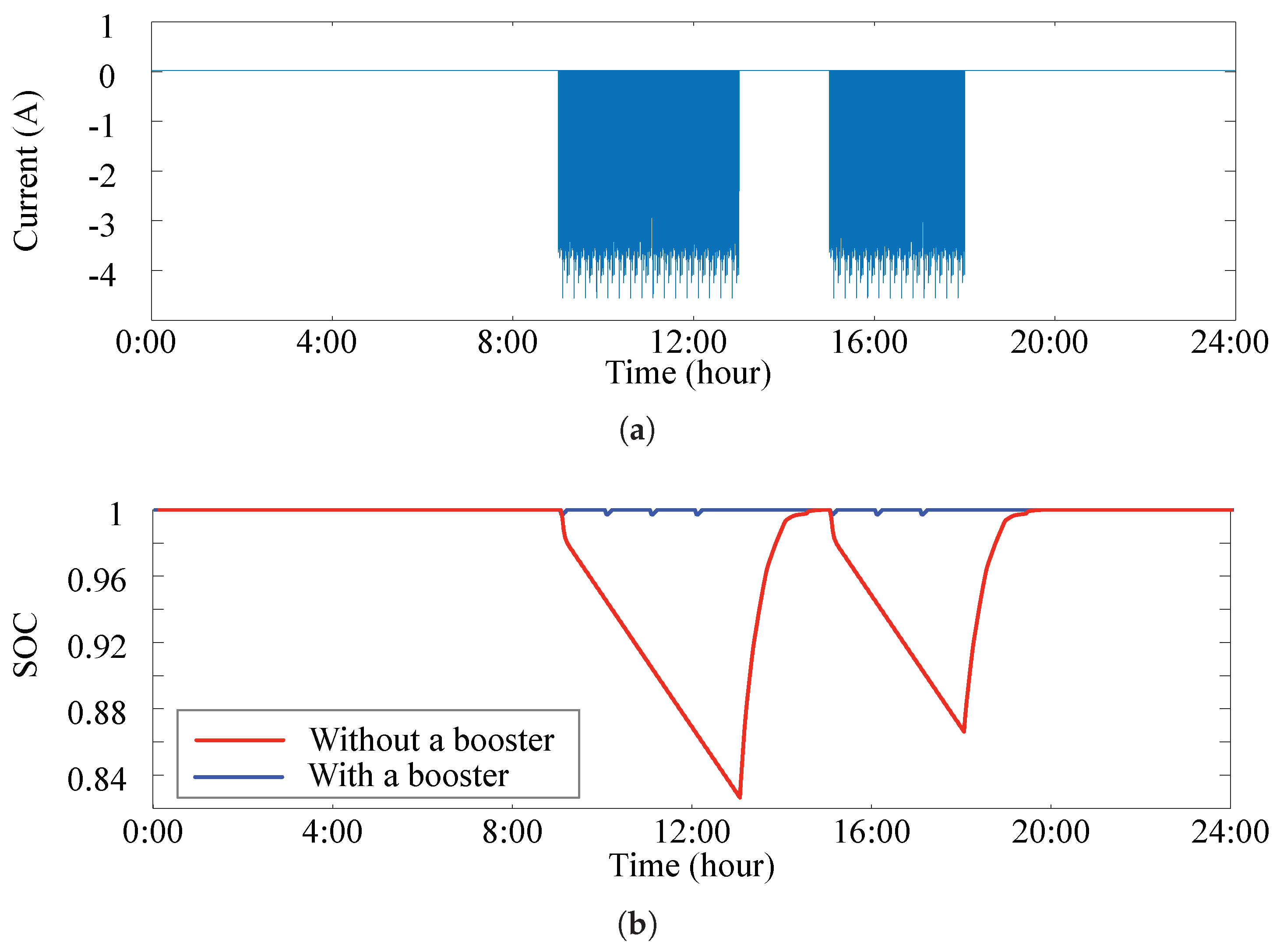
We verify the effect of designed booster by comparing the battery SOC variations between systems without a booster and with a booster. Figure 8 shows the comparison of the battery SOC variation during a day under the assumed usage profile. The red line and the blue line represents the battery SOC without and with the supercapacitor hybrid architecture, respectively. The optimal booster eliminates the SOC degradation due to the reduced capacity adapter effectively. There is small SOC degradation even though the system utilizes the optimal booster, as shown in Figure 8. The supercapacitor is charged by the adapter when is less than because the maximum capability of the reduced capacity adapter is more than the average power demand of workload.
However, the optimal booster does not guarantee that the supercapacitor is sufficiently charged to compensate the upcoming deficient energy peak because we decide the upper bound of the deficient energy to be compensated and the adapter capacity is limited. In that case, the battery suffers from the deficient power time to time, as shown in Figure 8.
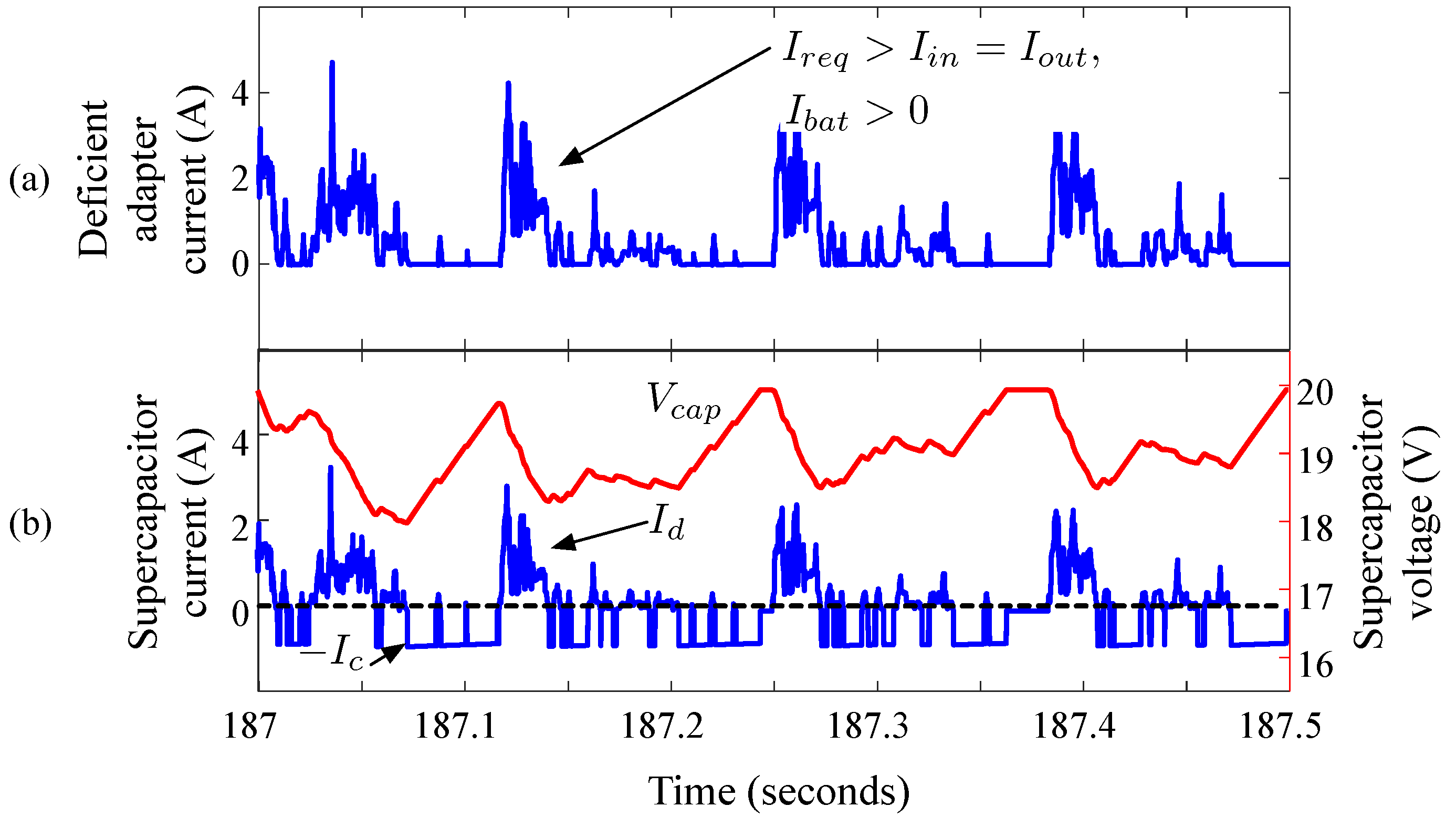
The booster effect is detailed in Figure 9. Figure 9a shows the deficient current from the reduced capacity adapter without a booster. If we use a booster, the deficient current is provided by the supercapacitor instead of the battery, as shown in Figure 9b. The red and the blue lines represent the supercapacitor voltage and current, respectively. The positive amount of the current indicates the discharge current from the supercapacitor to supply deficient adapter current and the negative amount of the current indicates the charge current to the supercapacitor from the power adapter , respectively. The terminal voltage of the supercapacitor, shown in Figure 9b, varies according to the stored energy, but it does not decrease below the lower bound we set. The result shows that the supercapacitor supplies enough power relative to deficient amount, and there is almost no aging of the built-in battery due to the reduced size power adapter.
We compare the estimated battery lifetime using Equation (1) when the battery is in idle state (the battery is not in use) and the battery is used without and with a booster as summarized in Table 2. We consider the battery in idle state with C as the baseline and normalize the life parameter of each cases to that of the baseline. A lifetime of 100% denotes the full 15 years of shelf life, while, e.g., 71.2% means that the battery capacity is reduced to 80% of its initial value after 10.7 years. The battery temperature is around C when it is used. Therefore, we first estimate the lifetime of batter in idle state with C to distinguish the battery aging due to temperature and the discharging and charging. The lifetime decreases as 71.1% of the baseline when the battery is stored in C. Using the laptop without a booster makes it worse and reduces the lifetime as 31.4%. The lifetime increases as 46.8% if we rely on the booster with 10 mF supercapacitor which is used in [6]. If we use the optimal booster designed by the proposed methodology, the lifetime of battery is enhanced as 49.6%. We also compare the increment of life parameter according to the time as shown in Figure 10. We compare L until L reaches 0.2 because the battery is depleted when L increases above than 0.2 typically. The results show that the proposed methodology mitigates the effect of reduced capacity adapter effectively.
The cost of including supercapacitors is important decision parameter for using the proposed supercapacitor hybrid architecture. We search and present the weight, dimension (volume), and retail price [23,24,25,26,27,28] of a reduced capacity adapter, a normal capacity adapter, and a supercapacitor in Table 3. Since the withstand voltage of target supercapacitor is only 3.3 V, we build a supercapacitor array with supercapacitor to design the optimal booster determined by the proposed methodology. The total weight increase by supercapacitor is less than 2 g and the volume increase due to supercapacitor is less than 17.2 , which only increases the width by 5 mm. Adding a booster costs only $21.6, which is reasonable compared to 135 W capacity adapter.
5. Conclusions
The reduced capacity adapter has numerous advantages such as a light-weight, small-form factor, and the reduced cost. However, it incurs significant battery aging with a heavy workload even while the laptop is supplied by the wall power. A supercapacitor–battery hybrid architecture is proposed to mitigate the unwelcome battery aging problem, but there is no systematic methodology to determine the specification of a supercapacitor. We propose a design methodology to maximize the enhancement of battery lifetime with the minimum cost. Finally, we confirm that the designed booster having 17.5 mF capacity and 20 V withstand voltage is enough to enhance the battery lifetime when a reduced capacity power adapter is used.
Author Contributions
Conceptualization, J.K. and D.S.; methodology, J.K. and D.S.; software, J.K.; validation, D.B. and J.P.; formal analysis, J.K. and D.S.; investigation, J.K.; resources, J.K.; data curation, J.K.; writing-original draft preparation, J.K.; writing-review and editing, J.P., D.B., and D.S.; visualization, J.K.; supervision, J.P.; project administration, J.P.; funding acquisition, J.P. and D.S.
Funding
This work was supported by the National Research Foundation of Korea (NRF) grant funded by the Korea government (MSIT) (Nos. NRF-2018R1C1B5047150 and NRF-2018R1D1A1B07049445).
Conflicts of Interest
The authors declare no conflict of interest.
References
- Intel, Product Information. Available online: http://ark.intel.com/products (accessed on 3 October 2018).
- Beyondinfinite, LP154WX4-TLC3 Datasheet. Available online: http://beyondinfinite.com/lcd/Library/LG-Philips/LP154WX4-TLC3.pdf (accessed on 3 October 2018).
- HGST, Travelstar-Z7K500 Datasheet. 2013. Available online: http://www.hgst.com/hard-drives/mobile-drives/7mm-thin-and-light-drives/travelstar-z7k500 (accessed on 3 October 2018).
- Kingston, KVR16N11-8 Datasheet. 2013. Available online: http://www.kingston.com/dataSheets/KVR16N11_8.pdf (accessed on 3 October 2018).
- TechPowerUp. Available online: https://www.techpowerup.com/gpu-specs/nvs-5400m.c1742 (accessed on 3 October 2018).
- Kim, J.; Pröbstl, A.; Chakraborty, S.; Chang, N. Aging mitigation of power supply-connected batteries. In Proceedings of the 2014 IEEE/ACM International Symposium on Low Power Electronics and Design (ISLPED), La Jolla, CA, USA, 11–13 August 2014. [Google Scholar]
- Shin, D.; Kim, Y.; Wang, Y.; Chang, N.; Pedram, M. Constant-Current Regulator-Based Battery-Supercapacitor Hybrid Architecture for High-Rate Pulsed Load Applications. JPS 2012, 205, 516–524. [Google Scholar] [CrossRef]
- Jing, W.; Lai, C.H.; Wong, S.H.W.; Wong, M.L.D. Battery-supercapacitor hybrid energy storage system in standalone DC microgrids: A review. IET Renew. Power Gener. 2016, 11, 461–469. [Google Scholar] [CrossRef]
- Kim, Y.; Raghunathan, V.; Raghunathan, A. Design and Management of Battery-Supercapacitor Hybrid Electrical Energy Storage Systems for Regulation Services. IEEE Trans. Multi-Scale Comput. Syst. 2017, 3, 12–24. [Google Scholar] [CrossRef]
- Carter, R.; Cruden, A.; Hall, P.J. Optimizing for Efficiency or Battery Life in a Battery/Supercapacitor Electric Vehicle. IEEE Trans. Veh. Technol. 2012, 61, 1526–1533. [Google Scholar] [CrossRef]
- Mesbahi, T.; Khenfri, F.; Rizoug, N.; Bartholomeüs, P.; Moigne, P.L. Combined Optimal Sizing and Control of Li-Ion Battery/Supercapacitor Embedded Power Supply Using Hybrid Particle Swarm–Nelder–Mead Algorithm. IEEE Trans. Sustain. Energy 2017, 8, 59–73. [Google Scholar] [CrossRef]
- Gee, A.M.; Robinson, F.V.P.; Dunn, R.W. Analysis of Battery Lifetime Extension in a Small-Scale Wind-Energy System Using Supercapacitors. IEEE Trans. Energy Convers. 2013, 28, 24–33. [Google Scholar] [CrossRef]
- Ongaro, F.; Saggini, S.; Mattavelli, P. Li-Ion Battery-Supercapacitor Hybrid Storage System for a Long Lifetime, Photovoltaic-Based Wireless Sensor Network. IEEE Trans. Power Electron. 2012, 27, 3944–3952. [Google Scholar] [CrossRef]
- Shin, D.; Poncino, M.; Macii, E. Thermal Management of Batteries Using Supercapacitor Hybrid Architecture With Idle Period Insertion Strategy. IEEE Trans. Very Large Scale Integr. (VLSI) Syst. 2018, 26, 1159–1170. [Google Scholar] [CrossRef]
- Krishna, C.M. Managing Battery and Supercapacitor Resources for Real-Time Sporadic Workloads. IEEE Embed. Syst. Lett. 2011, 3, 32–36. [Google Scholar] [CrossRef]
- Kim, Y.; Chang, N.; Wang, Y.; Pedram, M. Maximum Power Transfer Tracking for a Photovoltaic-Supercapacitor Energy System. In Proceedings of the 2010 ACM/IEEE International Symposium on Low-Power Electronics and Design (ISLPED), Austin, TX, USA, 18–20 August 2010. [Google Scholar]
- Kassem, M.; Bernard, J.; Revel, R.; Pélissier, S.; Duclaud, F.; Delacourt, C. Calendar aging of a graphite/LiFePO4 cell. JPS 2012, 208, 296–305. [Google Scholar] [CrossRef]
- Wanga, J.; Liua, P.; Hicks-Garnera, J.; Shermana, E.; Soukiaziana, S.; Verbruggeb, M.; Tatariab, H.; James Musserc, P.F. Cycle-life model for graphite-LiFePO4 cells. JPS 2011, 196, 3942–3948. [Google Scholar] [CrossRef]
- Millner, A. Modeling Lithium ion battery degradation in electric vehicles. In Proceedings of the 2010 IEEE Conference on Innovative Technologies for an Efficient and Reliable Electricity Supply, Waltham, MA, USA, 27–29 September 2010. [Google Scholar]
- Lam, L.; Bauer, P. Practical capacity fading model for Li-ion battery cells in electric vehicles. IEEE Trans. Power Electron. 2013, 28, 5910–5918. [Google Scholar] [CrossRef]
- Karagiannopoulos, S.; González, M.; Hildmann, M.; Andersson, G. Battery Modeling within Plug-in Vehicle Fleet Simulations in Smart-Grids. Master’s Thesis, ETH Zürich, Zürich, Switzerland, 2012. [Google Scholar]
- Choi, Y.; Chang, N.; Kim, T. DC–DC converter-aware power management for low-power embedded systems. IEEE Trans. Comput.-Aided Des. Integr. Circuits Syst. 2007, 26, 1367–1381. [Google Scholar] [CrossRef]
- Lenovo. 2018. Available online: http://shop.lenovo.com (accessed on 3 December 2018).
- Ebay. 2018. Available online: https://www.ebay.com/itm/90W-AC--Adapter-Charger-for-Lenovo-ThinkPad-T430s-T530-2352-CTO-239242U-i5-3320M-/121163900431 (accessed on 3 December 2018).
- Amazon. 2018. Available online: https://www.amazon.com/Genuine-Original-Adapter-Laptop-ThinkPad/dp/B079PXPZT6 (accessed on 3 December 2018).
- Ebay. 2018. Available online: https://www.ebay.com/itm/OEM-LENOVO-THINKPAD-BATTERY-45N1017-45N1016-28-0A36304-T430-T530-T410-W510/202283744193 (accessed on 3 December 2018).
- Digikey Corporation. 2018. Available online: http://www.digikey.com (accessed on 3 December 2018).
- AVX Corporation. 2018. Available online: http://datasheets.avx.com/BestCap.pdf (accessed on 3 December 2018).
Figure 1.
Suggested supercapacitor–battery hybrid system.

Figure 2.
The optimal booster design flow for the reduced capacity adapter.

Figure 3.
Current profile of gaming workload with an almost fully charged battery.

Figure 4.
The estimated battery SOC over time with reduced capacity adapter while running an exemplary daily usage profile, which consists of heavy workload profile as shown in Figure 3.
Figure 4.
The estimated battery SOC over time with reduced capacity adapter while running an exemplary daily usage profile, which consists of heavy workload profile as shown in Figure 3.

Figure 5.
Histogram and the cumulative ratio of deficient energy peaks when running the workload for gaming.
Figure 5.
Histogram and the cumulative ratio of deficient energy peaks when running the workload for gaming.

Figure 6.
The relation among the lower and the upper bound of the unit capacitor array voltage level and required capacitance to supply 2.3 J of deficient energy considering DC–DC converter efficiencies.
Figure 6.
The relation among the lower and the upper bound of the unit capacitor array voltage level and required capacitance to supply 2.3 J of deficient energy considering DC–DC converter efficiencies.

Figure 7.
The amount of usable energy from the unit capacitor array. The red line indicates the upper bound of deficient energy to be compensated which is 2.3 J.
Figure 7.
The amount of usable energy from the unit capacitor array. The red line indicates the upper bound of deficient energy to be compensated which is 2.3 J.

Figure 8.
The daily usage of load current and the comparison of battery SOC variation between the system without a booster and with a booster. (a) Daily usage of load current. (b) Daily battery SOC variation.
Figure 8.
The daily usage of load current and the comparison of battery SOC variation between the system without a booster and with a booster. (a) Daily usage of load current. (b) Daily battery SOC variation.

Figure 9.
(a) Deficient current from the adapter (b) Charge /discharge current of the supercapacitor and terminal voltage of the supercapacitor. The supercapacitor is managed to be charged or discharged exclusively. The supercapacitor is charged when and and the supercapacitor is discharged when and , respectively.

Figure 10.
Comparison of the estimated life parameter.


Table 1.
Maximum power consumption of Lenovo T530-2359-A44 and Apple MacBook Pro 2013 components [1,2,3,4,5].
| Component | CPU | VGA | LCD | HDD | RAM | Total | Adapter |
|---|---|---|---|---|---|---|---|
| T530 Power | 45 W | 35 W | 6 W | 5.5 W | 2.5 W | 94 W | 90 W |
| MacBook Power | 45 W | 45 W | 6.2 W | 5.5 W | 2.5 W | 104 W | 90 W |
Table 2.
Comparison of the estimated battery lifetime.
| Example Usage | Lifetime Comparison |
|---|---|
| Idle in C | 100 % |
| Idle in C | 71.2 % |
| Without a booster C | 31.4 % |
| With 10 mF supercapacitor, 4–15 V C | 46.8% |
| With 17.5 mF supercapacitor, 4–20 V C | 49.6% |
Table 3.
Comparison of weight, dimensions, and price of adapters and supercapacitors.
| Component | Weight (g) | Dimension (mm) W × D × H | Price |
|---|---|---|---|
| 90 W adapter | 360 | $10.59 | |
| 135 W adapter | 830 | $36.00 | |
| 22 mF Supercapacitor | $ | ||
| DC–DC converter with passive components | - | - | $6.65 × 2 |
| 90 W adapter + 22 mF Supercapacitor | 377.6 | $84.23 |
© 2019 by the authors. Licensee MDPI, Basel, Switzerland. This article is an open access article distributed under the terms and conditions of the Creative Commons Attribution (CC BY) license (http://creativecommons.org/licenses/by/4.0/).
Share and Cite
MDPI and ACS Style
Kim, J.; Shin, D.; Baek, D.; Park, J. Design and Optimization of Supercapacitor Hybrid Architecture for Power Supply-Connected Batteries Lifetime Enhancement. Electronics 2019, 8, 41. https://doi.org/10.3390/electronics8010041
AMA Style
Kim J, Shin D, Baek D, Park J. Design and Optimization of Supercapacitor Hybrid Architecture for Power Supply-Connected Batteries Lifetime Enhancement. Electronics. 2019; 8(1):41. https://doi.org/10.3390/electronics8010041
Chicago/Turabian StyleKim, Jaemin, Donghwa Shin, Donkyu Baek, and Jaehyun Park. 2019. "Design and Optimization of Supercapacitor Hybrid Architecture for Power Supply-Connected Batteries Lifetime Enhancement" Electronics 8, no. 1: 41. https://doi.org/10.3390/electronics8010041
Note that from the first issue of 2016, this journal uses article numbers instead of page numbers. See further details here.