Characteristic Mode Analysis and Design of Wide Band MIMO Antenna Consisting of Metamaterial Unit Cell


School of Electronics and Information Engineering, Hebei University of Technology, Tianjin 300401, China
*
Author to whom correspondence should be addressed.
Electronics 2019, 8(1), 68; https://doi.org/10.3390/electronics8010068
Submission received: 1 December 2018
/
Revised: 22 December 2018
/
Accepted: 2 January 2019
/
Published: 8 January 2019
(This article belongs to the Special Issue Intelligent Antennas)
Abstract
:This paper presents a full wave simulation and characteristic mode-based design of a multiple-input-multiple-output (MIMO) antenna at 5.8 GHz for wireless local area network applications. The driven analysis comprises two antennas that are placed orthogonal to each other. A metamaterial unit structure in the form of a rectangular loop resonator is placed around the antenna element to reduce the electromagnetic interference and to increase the isolation between the two monopoles. A characteristic mode technique is employed to find out the dominant mode of the proposed antenna without a feeding port. It was revealed that mode 1 was the dominant mode among the three modes used. The MIMO antenna is constructed and measured using a vector network analyzer. A good isolation of less than 25 dB was attained with a wide impedance bandwidth of 65.5%.
1. Introduction
The increasing demand for higher data throughput and the need for more reliable connections has motivated the use of multiple antenna techniques, which is a key feature for increasing the performance of wireless communication systems. In order to improve high data rates and secrecy, multiple antennas can be applied with spatial multiplexing, moreover, channel capacity can be greatly increased without sacrificing the spectrum of frequency and transmit power [1,2,3,4]. Multiple-input-multiple output (MIMO) antennas should have multiple ports and it is expedient to have those ports isolated and well matched as no matching network is connected. Although, different applications will have different properties when it comes to design, the major challenge faced by many space-limited applications are the difficulties in implementation and the increasing commutation in spatial diversity [5]. Another challenge facing the design of MIMO antenna are the electromagnetic interactions among the array elements called mutual coupling [6]. When several antenna elements are placed close proximity to each other, the electric field generated by one antenna alters the current distribution on the other antennas, therefore, the radiation pattern and input impedance of each array element are distributed based on the presence of the other elements [7]. The effect of mutual coupling severely degrades how the MIMO system performs, due to that, all the antenna elements have to be considered together as one aperture. In order to reduce the space and mutual coupling between the antenna elements, researchers have used various methods including the use of defected ground structure s(DGS) [8,9], neutralization lines [10] and electromagnetic band gap (EBG) structures [11,12]. Metamaterials have attracted much interest over the last few years, as they introduce interesting possibilities for how to improve antenna performance; they are used as a protective measure between two radiating elements to control and limit propagation among antenna elements and to lower the electromagnetic interactions among them [13,14,15,16]. Some interesting designs has been reported in the recent literature on the use of metamaterials to increase the isolation of an antenna. A letter presented in [17] demonstrated the use of a split rectangular loop resonator inspired MIMO monopoles for a global system for mobile (GSM)/long-term evolution (LTE)/wireless local area network (WLAN) applications, where a long stub together with four metamaterial unit cells was used. The use of a complementary split ring resonator (CSRR) has been studied in [18,19] where the CSRR is used to lower the resonant frequency of the radiating element as well as to produce multiple resonance. The work in [19] used a split ring resonator, which was placed between the two elements so as to increase the isolation characteristics higher than 15 dB over the band of interest.
Characteristic mode analysis (CMA) has become a favorable tool for analyzing and designing antennas, mainly due to the physical insight gained about antenna operating principles without considering any particular feeding [20]. Characteristic mode theory is a modal analysis technique for antennas of arbitrary shape. It also gives a clear understanding of the resonating frequency of specific modes, radiation patterns and the corresponding mode current [21,22,23,24,25]. The use of characteristic mode theory for the design and analysis of antennas has been investigated in the recent literature. For instance, a MIMO handheld antenna design using characteristic mode technique was realized in [26]. Similarly, a multi-port multiband chassis-mode antenna design using characteristic modes was analyzed in [27]. A pattern reconfigurable MIMO antenna was designed using CMA in [28]. Another MIMO antenna, with low mutual coupling and low correlation, was designed and analyzed using CMA in [29]. However, none of the above mentioned techniques utilized metamaterial. In this study, six metamaterial unit cells are used in exciting three different modes using a multilayer solver in computer simulation technology (CST). Characteristic mode theory was originally proposed in 1970 by Garbacz [30], and further refined by Harrington [31]. The characteristic modes are obtained by solving an eigenvalues equation that is deduce from the method of moment matrix, separated in to real and imaginary components, as shown in the following equations:
where is the method of moment impedance matrix, which has to be symmetrical to a large degree to get real and imaginary current [32]. is the eigenvalue, R and X represent the real and imaginary part of the impedance matrix. Two important parameters, the characteristic angle [33] and the modal significance [34] are obtained with the eigenvalue. The resulted response of a given antenna can be express in terms of its characteristic modal response as:
where Cn are the coefficient to be determined, and once the coefficient is obtained then Equation (3) can become:
From Equations (2) and (3), the expression for will be:
Note that MS is the modal significance and is the weighted excitation coefficient which represents how strongly a mode is excited. In this study, we used a transient analysis solver to analyze and design a MIMO antenna using metamaterial unit cells to give an insight regarding the isolation improvements of MIMO antenna. The major contributions of this work are summarized as follows:
- A full wave simulation tool was used to analyze the performance of MIMO antenna.
- A technique that utilizes metamaterial unit cell structure was developed with the aim of increasing isolation between MIMO radiating elements.
- More than 25 dB of isolation was achieved in the design considered.
- Used a characteristic mode to offer physical insight about antenna operating principles and to find the resonating frequency of specific modes.
- Construction and measurement of a MIMO antenna to verify the design concept and to confirm the simulated results.
The rest of the study is organized as follows. Section 2 presents the parametric analysis of the design to come up with best values of the geometry, Section 3 characterizes the proposed MIMO antenna design using full wave simulation. Section 4 presents the analysis and design of the MIMO antenna using characteristic mode theory. Section 5 is the diversity analysis of the MIMO antenna, and Section 6 concludes the letter.
2. Parametric Analysis of the Design
The parametric analysis is presented using different values of P from the geometry, to have best values that can give us a better performance of the antenna, in terms of its reflection coefficient. Figure 1 shows the S11 for various length of P, it clearly shows that when the value of P was 23 mm, the S11 was at 5.8 GHz, which is the required frequency band of interest. Though the remaining plots are also within the range of −10 dB.
Another analysis was set up, but this time around it was for metamaterial unit cells, the results show the effect of adding up to six in both S11 and S21. Figure 2 pictures the S11 of different unit cells, with six unit cells giving a better matching of the input impedance. Figure 3 is the plot for the isolation of the antenna, it is clearly shows that as the unit cells increased, the isolation also increased which signifies that the introduction of metamaterial unit cells enhanced the performance of the antenna and increased the isolation between the MIMO antenna.
3. Antenna Design and Simulation Using Full Wave Simulation
The geometry of the two element MIMO monopole is pictured in Figure 4a,b. The design was performed using computer simulation technology version 2017 (CST AG, Darmstadt, Germany). The MIMO antenna was mounted on an FR4 substrate with a relative permittivity of 4.3, a 0.025 loss tangent and height of 1.6 mm. the system consist of two printed patches on top separate by a distance of 0.29 (22 mm) (top view) and a ground plane (bottom view), where is the free space wavelength. The distance between the two antennas was not too wide and at the same time was not too close, which is why the decoupling structure was employed to reduce the interference. Two rows of split rectangular loop resonators were placed around the two antenna element. Each row contained six elements which is quite enough to give perfect inductance. The total design area was 40 × 80 mm2. Figure 5a,b shows a two-dimensional and 3D view of a metamaterial unit cell, which was etched on a 1.6 mm thick FR4 epoxy substrate with a dielectric constant of 4.3 at a frequency of 1–12 GHz. Both the parameters of Figure 4 and Figure 5 are pictured in Table 1 and Table 2. Figure 5b shows a unit cell dimension of 3 × 4.8 × 1.6 on xyz coordinates. The z-axis is the negative magnetic permeability for the boundary condition while the x-axis is a two opening where the port was inserted which propagates the wave, and finally the y-axis is perfectly electric. The electric permittivity retrieval was set using the S-parameter retrieval technique.
The remaining dimensions of the rectangular loop resonator are fixed except m, which is the gap capacitance that is controlled by the length of k, the value of k was chosen to be 1.75 mm after a series of optimizations because the resonant frequency changed correspondingly from 4−8 GHz. Figure 6a and Figure 3b show the top and bottom views of the constructed design containing the two-element of the MIMO antenna together with six-unit rectangular cells placed around them. Figure 7 presents the measured and simulated S11, and Figure 8 is the measured and simulated voltage standing wave ratio of the MIMO system. The measured and simulated isolation (S21) is pictured in Figure 9. The construction of the MIMO antenna and measurement were carried out at the Institute of Micro-nano Photoelectronic and Electromagnetic Technology Innovation School of Electronics and Information Engineering, Hebei University of Technology, China using N5244A network analyzer. The measured and simulated impedance width and voltage standing wave ratio (VSWR < 2−10 dB) of the design was 65.5%, ranging from 4.2 GHz to 8 GHz. The metamaterial unit cell permeability, real and imaginary parts, is shown in Figure 10 while Figure 11 is the MTM S11 and S21.
4. Characteristic Mode Analysis of the MIMO Antenna
The theory of characteristic mode was applied to the two-element MIMO monopole antenna without feeding structure using a multi-layer solver in computer simulation technology version 2017. It represents the normalized amplitude of the current modes. This normalize amplitude does not depend on the feeding port but only depends on the shape and size of the conducting object. Figure 12 shows the modal significance of three modes, as can be seen that only mode 1 had modal significance of up to 1 at the resonant frequency of 5.8 GHz. Mode 2 and mode 3 were at 5.5 GHz and 4.8 GHz. Therefore, mode 1 will become dominant in the antenna. Figure 13 presents the characteristics angle for the MIMO antenna at three different modes. Characteristic angle is defined in [31] as:
Equation (5) gives a better interpretation of how energy is stored in the MIMO array. When the characteristic angle is 180° the mode resonates, when it is less than 180° the mode stores magnetic energy and when it is greater than 180° the mode stores electric energy. From Figure 13, mode 1 was almost at 5.8 GHz and remained the resonance frequency of interest. Figure 14 presents the modal surface current and modal 3D radiation pattern of different modes at 5.8 GHz. We can see that mode 1, being the dominant mode, had more gain as compared to the others which means mode 1 was also playing a significant role in terms of reducing the mutual coupling of the MIMO antenna. Figure 15 present the eigenvalue for the three modes at the resonant frequency. From the results it was clearly shown that the three modes were resonant with = 0 but mode 1 was more dominant. Figure 16, Figure 17 and Figure 18 are the normalized 2D radiation patterns at 5.8 GHz for modes 1, 2 and 3. The pattern shows the E and H planes for the antenna element at 5.8 GHz.
5. Diversity analysis of the MIMO antenna
To verify the capability of MIMO antenna, it is important to have a low envelope correlation coefficient and a diversity gain of nearly 10 dB. The ECC are computed using the far field radiation pattern as calculated in Equation (6) [35]:
where is the far field property of the MIMO antenna after exciting port I and * stand as the multiplication sign, the proposed MIMO antenna ECC was calculated from 1 to 8 GHz. The diversity gain of MIMO antennas can be calculated from the ECC as:
Figure 19 shows the ECC of the MIMO antenna with less than 0.002 over the entire frequency range. Figure 20 shows the diversity gain of nearly 10 dB. While Figure 21 is the peak gain over the entire frequency range.
A comparison among the reported antenna and this study is summarized in Table 3, in terms of impedance width, isolation, ECC and efficiency of the MIMO system. From Table 3, it is indicated that compared to all other refered structures, the proposed split rectangular loop resonator exhibits the highest value of S21 indicating its high isolation. The proposed MIMO antenna presents wider impedance bandwidth cimpared to [16,21,28,29] and offers a simple design as compared to the complex structure reported in [12].
6. Conclusions
In this paper, a linearly polarized wideband MIMO antenna consisting of metamaterial unit cells is presented. We used two radiating MIMO elements in the design and analysis. Employing metamaterial unit cells affects the isolation curve, with an isolation of less than 25 dB. The characteristic mode analysis shows that mode 1 has a dominant mode. The simulated and measured results demonstrated good performance of the proposed wideband MIMO antenna including an efficiency value of higher than 70% with an ECC of less than 0.002 and diversity gain of 0.99 dB, which is very good for 5.8 GHz WLAN applications.
Author Contributions
A.H.J. and A.A. design and analyze the study. A.H.J., A.A. and Z.S. perform the experiments. A.H.J. and Z.S. measure the antenna. A.H.J. write the paper. H.-X.Z. supervises the manuscript.
Funding
The research is supported by the National Natural Science Foundation of China under grant 61671200, and the key project of Hebei Province Natural Science Foundation under grant F20172202283).
Conflicts of Interest
The authors declare no conflict of interest.
Abbreviations
The following abbreviation are used in the manuscript:
| MIMO | Multiple-Input-Multiple-Output |
| CMA | Characteristic mode analysis |
| LTE | Long term evolution |
| WIMAX | Worldwide interoperability for microwave access |
| CSRR | Complementary split ring resonator |
| VSWR | Voltage standing wave ratio |
| MTM | Metamaterial |
| MS | Modal significance |
| ECC | Envelope correlation coefficient |
| DG | Diversity gain |
| BW | Bandwidth |
| GSM | Global system for mobile |
| LTE | Long term evolution |
| WLAN | Wireless local area network |
References
- Wu, Y.; Ding, K.; Zhang, B.; Li, J.; Wu, D.; Wang, K. Design of a compact UWB MIMO antenna without decoupling structure. Int. J. Antenna Prop. 2018, 2018. [Google Scholar] [CrossRef]
- Ali, W.A.E.; Ibrahim, A.A. A compact double-sided MIMO antenna with an improved isolation for UWB applications. Int. J. Electron. Commun. 2017, 82, 7–13. [Google Scholar] [CrossRef]
- Li, K.; Shi, Y. Wideband MIMO handset antenna design based on theory of characteristic modes. Int. J. RF Microw. Comput. Aided Eng. 2018, 28. [Google Scholar] [CrossRef]
- Abiodun, O.; Yang, H.; Wu, Y. Enhancing the security of wireless communication with the aid of guard nodes. J. Commun. 2016, 11, 586–591. [Google Scholar] [CrossRef]
- Christos, M.; Michail, M. Space-constrained massive MIMO: Hitting the wall of favorable propagation. IEEE Commun. Lett. 2015, 19, 771–774. [Google Scholar] [CrossRef]
- Kundu, L. Information Theoretic Limits on MIMO Antennas. Ph.D. Thesis, North Carolina State University, Raleigh, NC, USA, 2016. [Google Scholar]
- Qian, K.-W.; Huang, G.-L.; Liang, J.-J.; Qian, B.; Yuan, T. An LTCC interference cancellation device for closely spaced antennas decoupling. IEEE Access 2018, 6, 68255–68262. [Google Scholar] [CrossRef]
- Iqbal, A.; Saraereh, O.A.; Ahmad, A.W.; Bashir, S. Mutual coupling reduction using F-shaped stubs in UWB-MIMO antenna. IEEE Access 2018, 6, 2755–2759. [Google Scholar] [CrossRef]
- Luo, C.-M.; Hong, J.-S.; Zhong, L.-L. Isolation enhancement of a very compact UWB-MIMO slot antenna with two defected ground structures. IEEE Antennas Wirel. Propag. Lett. 2015, 14, 1766–1769. [Google Scholar] [CrossRef]
- Lee, C.H.; Chen, S.Y.; Hsu, P. Integrated dual planar inverted F antenna with enhanced isolation. IEEE Antennas Wirel. Propag. Lett. 2009, 8, 963–965. [Google Scholar]
- Dabas, T.; Gangwar, D.; Kumar, B.K.; Gautam, A.K. Mutual coupling reduction between elements of UWB MIMO antenna using small size uniplanar EBG exhibiting multiple stop bands. Int. J. Electron. Commun. 2018, 93, 32–38. [Google Scholar] [CrossRef]
- Farahani, H.S.; Veysi, M.; Kamyab, M.; Tadjalli, A. Mutual coupling reduction in patch antenna array using a UC-EBG superstrate. IEEE Antennas Wirel. Propag. 2010, 9, 57–59. [Google Scholar] [CrossRef]
- Liu, Z.-T.; Qu, S.-B.; Wang, J.-F.; Zhang, J.-Q.; Hua, M.; Xu, Z.; Zhang, A.-X. Isolation enhancement of patch antenna array via metamaterial integration. Microw. Opt. Technol. Lett. 2016, 58, 2321–2325. [Google Scholar] [CrossRef]
- Marathe, D.; Kulat, K. A compact dual, triple band resonators for negative permittivity metamaterial. Int. J. Electron. Commun. 2018, 8, 157–165. [Google Scholar] [CrossRef]
- De Almeida, J.V.; Siwueira, G.L. Experiments on metamaterials for sub-wavelength antenna isolation at PEC boundaries. Microw. Opt. Technol. Lett. 2017, 59, 1420–1423. [Google Scholar] [CrossRef]
- Amjad, I.; Omar, A.S.; Amal, B.; Abdul, B. Metamaterial-based highly isolated MIMO antenna for portable wireless applications. Electronics 2018, 7, 267. [Google Scholar] [CrossRef]
- Jabire, A.H.; Zheng, H.-X.; Abdu, A. Split rectangular loop resonator inspired MIMO monopoles for GSM/LTE/WLAN applications. J. Commun. 2019, 14. in press. [Google Scholar]
- Khan, M.U.; Sharawi, M.S. A 2x1 multiband MIMO antenna system consisting of miniaturized patch elements. Microw. Opt. Technol. Lett. 2014, 56, 1371–1375. [Google Scholar] [CrossRef]
- Ajay Yadav, S.A.; Yadav, R.P. SRR and S-shape slot loaded triple band notched UWB antenna. Int. J. Electron. Commun. 2017, 192–198. [Google Scholar] [CrossRef]
- Capek, M.; Losenicky, V.; Jelinek, L.; Gustafsson, M. Validating the characteristic mode solvers. IEEE Trans. Antennas Propag. 2017, 65, 4134–4145. [Google Scholar] [CrossRef]
- Dong, W.K.; Nam, S. Systematic design of a multiport MIMO antenna with bilateral symmetry based on characteristic mode analysis. IEEE Trans. Antennas Propag. 2018, 66, 1076–1085. [Google Scholar]
- Chen, Y.; Wang, C.F. Characteristic Modes: Theory and Applications in Antenna Engineering; Wiley: Hoboken, NJ, USA, 2015. [Google Scholar]
- Chen, Y.; Wang, C.F. HF band ship board antenna design using characteristic modes. IEEE Trans. Antennas Propag. 2015, 63, 1004–1013. [Google Scholar] [CrossRef]
- Liang, P.; Wu, Q. Characteristic mode analysis of antenna mutual coupling in the near field. IEEE Trans. Antennas Propag. 2018, 66, 3757–3762. [Google Scholar] [CrossRef]
- Martens, R.; Manteuffel, D. Systematic design method of a mobile multiple antenna system using the theory of characteristic modes. IET Microw. Antennas Propag. 2014, 8, 887–893. [Google Scholar] [CrossRef]
- Ethier, J.; Lanoue, E.; Mcnamara, D. MIMO handheld antenna design approach using characteristic mode concepts. Microw. Opt. Technol. Lett. 2008, 50, 1724–1727. [Google Scholar] [CrossRef]
- Kumar Kishor, K.; Victor Hum, S. Multiport multiband chassis-mode antenna design using characteristic modes. IEEE Antennas Wirel. Propag. Lett. 2017, 16, 609–612. [Google Scholar] [CrossRef]
- Li, K.; Shi, Y. A pattern reconfigurable MIMO antenna design using characteristic modes. IEEE Access 2018, 6, 43526–43534. [Google Scholar] [CrossRef]
- Kim, J.; Qu, L.; Jo, H.; Zhang, R.; Kim, H. A MIMO antenna design based on the characteristic modes. Microw. Opt. Technol. Lett. 2017, 59, 893–898. [Google Scholar] [CrossRef]
- Garbaiz, R.J. A Generalized Expansion for Radiated Scatter Fields. Ph.D. Thesis, Ohio University, Columbus, OH, USA, 1968. [Google Scholar]
- Harrington, R.F.; Mautz, J.R. Theory of characteristic modes for conducting bodies. IEEE Trans. Antennas Propag. 1971, 19, 622–628. [Google Scholar] [CrossRef]
- Austin, B.A.; Murray, K.P. The application of characteristic mode technique to vehicle mounted NVIS antennas. IEEE Antennas Propag. Mag. 1998, 40, 7–21. [Google Scholar] [CrossRef]
- Newman, E.H. Small antenna location synthesis using characteristic modes. IEEE Trans Antenna Propag. 1971, 27, 530–531. [Google Scholar] [CrossRef]
- Ikram, M.; Hussain, R.; Hamm, O.; Sharawi, M.S. An l-shaped 4 element monopole MIMO antenna system with enhanced isolation for mobile applications. Microw. Opt. Technol. Lett. 2016, 58, 2587–2591. [Google Scholar] [CrossRef]
- Sharawi, M.S. Printed MIMO Antenna Engineering; Artech House: Norwood, MA, USA, 2014. [Google Scholar]
Figure 1.
S11 plot for various length of P.

Figure 2.
S11 plot for various quantity of metamaterial unit cell.

Figure 3.
S21 plot for various quantity of metamaterial unit cell.

Figure 4.
Antenna geometry; top view (a), bottom view (b).

Figure 5.
Metamaterial unit cell; 2D view (a), 3D view (b).

Figure 6.
Fabricates antenna; top view (a), bottom view (b).

Figure 7.
Measured and simulated S11.

Figure 8.
Measured and simulated VSWR.
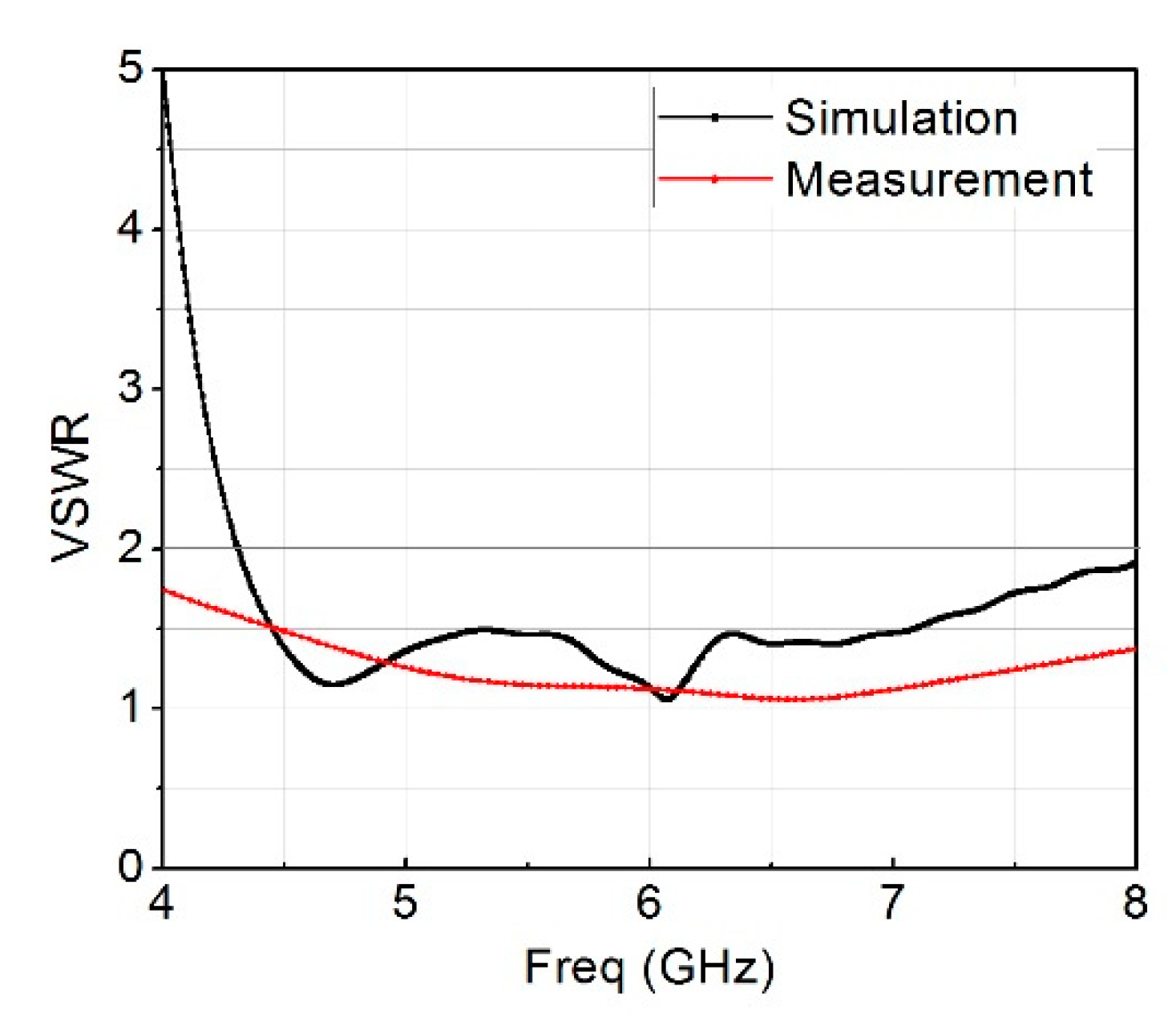
Figure 9.
Measured and simulated S21.

Figure 10.
Metamaterial permeability, real & imaginary parts.

Figure 11.
Metamaterial S11 & S21.

Figure 12.
Modal significance of three modes at 5.8 GHz.

Figure 13.
Characteristic angle of three modes at 5.8 GHz.

Figure 14.
Eigenvalues of three modes at 5.8 GHz.

Figure 15.
Modal surface current and modal 3D radiation pattern of 3 modes at 5.8 GHz; (a,b) mode 1, (c,d) mode 2, (e,f) mode 3.
Figure 15.
Modal surface current and modal 3D radiation pattern of 3 modes at 5.8 GHz; (a,b) mode 1, (c,d) mode 2, (e,f) mode 3.

Figure 16.
Radiation pattern for mode 1 at 5.8 GHz.

Figure 17.
Radiation pattern for mode 2 at 5.8 GHz.
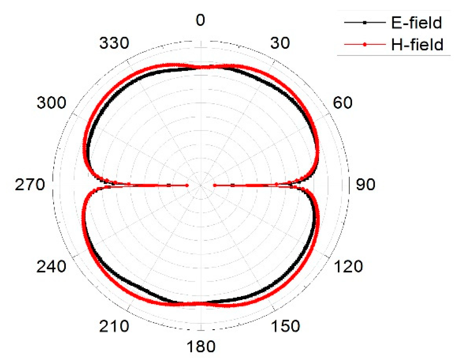
Figure 18.
Radiation pattern for mode 3 at 5.8 GHz.
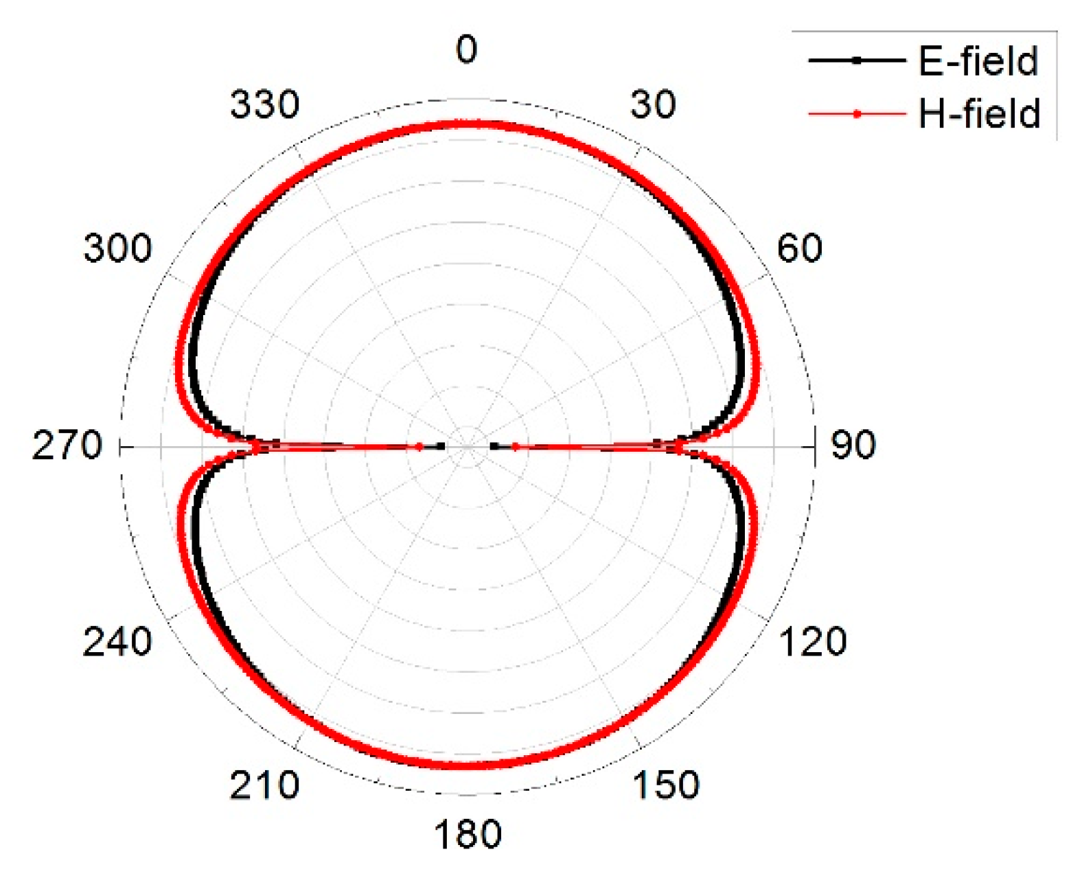
Figure 19.
Envelope correlation coefficient of the MIMO antenna.

Figure 20.
Diversity gain of the MIMO antenna.

Figure 21.
Maximum gain over frequency.


Table 1.
Optimized antenna parameters.
| Parameter | Value (mm) | Parameter | Value (mm) |
|---|---|---|---|
| G | 0.6 | R | 15.5 |
| H | 1.6 | S | 7 |
| L | 40 | T | 3.5 |
| Lg | 11 | W | 80 |
| P | 10.25 | Wg | 40 |
| Q | 14 | X | 2 |
Table 2.
Metamaterial unit cell parameters.
| Parameter | Value (mm) | Parameter | Value (mm) |
|---|---|---|---|
| g | 3 | k | 1.75 |
| h | 1.6 | l | 0.2 |
| i | 4.8 | m | 1 |
| j | 2.4 | n | 4.2 |
© 2019 by the authors. Licensee MDPI, Basel, Switzerland. This article is an open access article distributed under the terms and conditions of the Creative Commons Attribution (CC BY) license (http://creativecommons.org/licenses/by/4.0/).
Share and Cite
MDPI and ACS Style
Jabire, A.H.; Zheng, H.-X.; Abdu, A.; Song, Z. Characteristic Mode Analysis and Design of Wide Band MIMO Antenna Consisting of Metamaterial Unit Cell. Electronics 2019, 8, 68. https://doi.org/10.3390/electronics8010068
AMA Style
Jabire AH, Zheng H-X, Abdu A, Song Z. Characteristic Mode Analysis and Design of Wide Band MIMO Antenna Consisting of Metamaterial Unit Cell. Electronics. 2019; 8(1):68. https://doi.org/10.3390/electronics8010068
Chicago/Turabian StyleJabire, Adamu Halilu, Hong-Xing Zheng, Anas Abdu, and Zhiwei Song. 2019. "Characteristic Mode Analysis and Design of Wide Band MIMO Antenna Consisting of Metamaterial Unit Cell" Electronics 8, no. 1: 68. https://doi.org/10.3390/electronics8010068
Note that from the first issue of 2016, this journal uses article numbers instead of page numbers. See further details here.