Modeling and Analysis of Wearable Antennas


1
Department of Communications Engineering, King Abdullah II School of Engineering, Princess Sumaya University for Technology PSUT, Amman 11941, Jordan
2
Department of Electrical Engineering, The Hashemite University, Zarqa 13133, Jordan
3
Department of Electrical Engineering, University of Engineering & Technology, Peshawar 814, Pakistan
4
School of Intelligent Mechatronics Engineering, Sejong University, Seoul 05006, Korea
*
Author to whom correspondence should be addressed.
Electronics 2019, 8(1), 7; https://doi.org/10.3390/electronics8010007
Submission received: 24 November 2018
/
Revised: 13 December 2018
/
Accepted: 19 December 2018
/
Published: 21 December 2018
(This article belongs to the Special Issue Wearable Electronic Devices)
Abstract
:This paper describes a sheet-like transmission line for constructing a short-range wireless communication system using flexible materials such as clothing. As a new application of wireless communications, it is desired to construct a Personal Area Network (PAN) and a sensor network with a short distance communication area of about 1 m to 2 m. For such applications, a waveguide of a new structure is required which can exchange information at an arbitrary place on the waveguide, which has a flexible structure and limits the area for wireless communication. Therefore, by disposing the microstrip type resonators two-dimensionally with a two-layer structure and electromagnetically strongly coupling the resonators, the electromagnetic waves are confined well within the transmission line, and the antenna of the wireless device resonator is arranged. Furthermore, by constructing this transmission line with a sheet-like flexible wearable material, the transmission of both information and power can be performed through a thin flexible transmission line for the wearable network.
1. Introduction
Wired communications using coaxial cables and optical fibers, and wireless communications that propagate electromagnetic waves in free space using antennas, are common forms of communications. Wired communications have low propagation loss due to the communication line, and for this reason, they are advantageous for high-speed communications and high security. On the other hand, since wireless communications dramatically improve the working environment by eliminating cables, its application is spreading even for short distance communications. A sheet-like waveguide is a form of communications that incorporates the advantages of both wired and wireless communications. Compared to wireless communications, the loss due to the communication line is small and the security is high. Moreover, since the communication line is sheet-like, it can be used on the floor or the desk so that it can improve the working environment. Notably if you can construct a transmission line with a flexible material, you can wear it in a similar way to clothes, and you can achieve a good affinity with wearable devices through activities such as sensing of biological activity information and its transmission. Various applications may be expected for this technology such as monitoring of medical data and developing multifunction suits for rescue workers. Also, if wired communication with cables is expressed as one-dimensional communication, and wireless communication using antenna radiation is expressed as three-dimensional communication, communication by a sheet-like waveguide can be expressed as two-dimensional communication and can be thought of as a new physical layer of communication.
In recent years, wearable technology has developed rapidly. This technology combines electronic technology, biotechnology and medical technology [1,2]. In order to cope with wireless communication problems between wearable devices, the concept of a body area network (BAN) is proposed [3,4,5]. The most basic and most important part of the body area network is the wireless transceiver antenna. Sensor flexibility trend requires that the communication antenna should also have flexible ductility. However, the traditional antenna manufacturing process uses a rigid substrate while using a metal material with good electrical conductivity but no flexibility, resulting in the conventional antenna not having flexibility, while the conventional antenna has deformation occur during stretching, resulting in rapid deterioration of antenna performance, which is difficult to apply in the flexible wearable field. In order to cope with this challenge, some new materials with excellent characteristics have been developed, and the emergence of new materials provides more freedom for antenna design. Currently, flexible antennas are designed in the industry to make antennas using new flexible conductive materials, such as conductive composites [6], metal films [7] or liquid alloys [8,9] to further enhance the ductile properties of the antennas. The flexibility of the antenna is improved, although the exploration of the flexible ductile antenna structure is less so. It can guarantee the stability of the working bandwidth of the antenna and good impedance matching. This paper also analyzes the effects of stretching in different directions on the performance of the antenna, including the bandwidth, input impedance and the change of the pattern.
To achieve a full integration of a wearable system into smart clothing and protective garments, several wearable textile antennas have also been presented [8,9,10,11,12,13,14,15,16]; some conventional planar antenna layouts have been implemented by using electrotextiles (embroidered conductive polymer fibers, Shieldit®, Flectron®) and non-conductive textile substrates (fleece fabric, cotton/polyester, felt, flexible pad foam commonly available in protective garments, Cordura layers, etc.). Specific attention has been devoted to antenna layouts that avoid weak soldering connections [17] and also preferring antenna configurations exhibiting a lower sensitivity to the variations of both the non-conductive layer thickness and the textile material permittivity and conductivity.
However, the above literature lacks consideration of many important factors such as lack of one- and two-dimensional analysis, power and information transmission and flexibility. As an approach to sheet waveguide, we applied functions such as power supply, location search, time synchronization, direction search, communication, etc. to the surface using an array of microcoils and electromagnets for application to sensor networks, and an intelligent surface which utilized the MAGIC-Surface [18,19]. There was a problem of cost because magnetic devices were used. Also, a two-dimensional communication sheet which is easy to manufacture has been studied using a structure in which an insulating material such as a foamed urethane is sandwiched between a ground plate and a conductive mesh layer [20,21,22].
A sheet-like waveguide (free access mat) that is easy to manufacture and can excite the waveguide with an arbitrary antenna has been proposed [23]. In this paper, we describe the electromagnetically coupled ribbon wire interconnect used to cross the line which becomes the basis of this waveguide [24]. We describe the characteristics of one - dimensional and two - dimensional line using this structure. We also provide an example in which a two-dimensional waveguide using a conductive cloth is applied to a wearable transmission line will also be described. This also clarifies that electric power, as well as information, can be supplied.
2. Sheet-Like Transmission Line
2.1. Information Transmission by a Sheet-Like Transmission Line
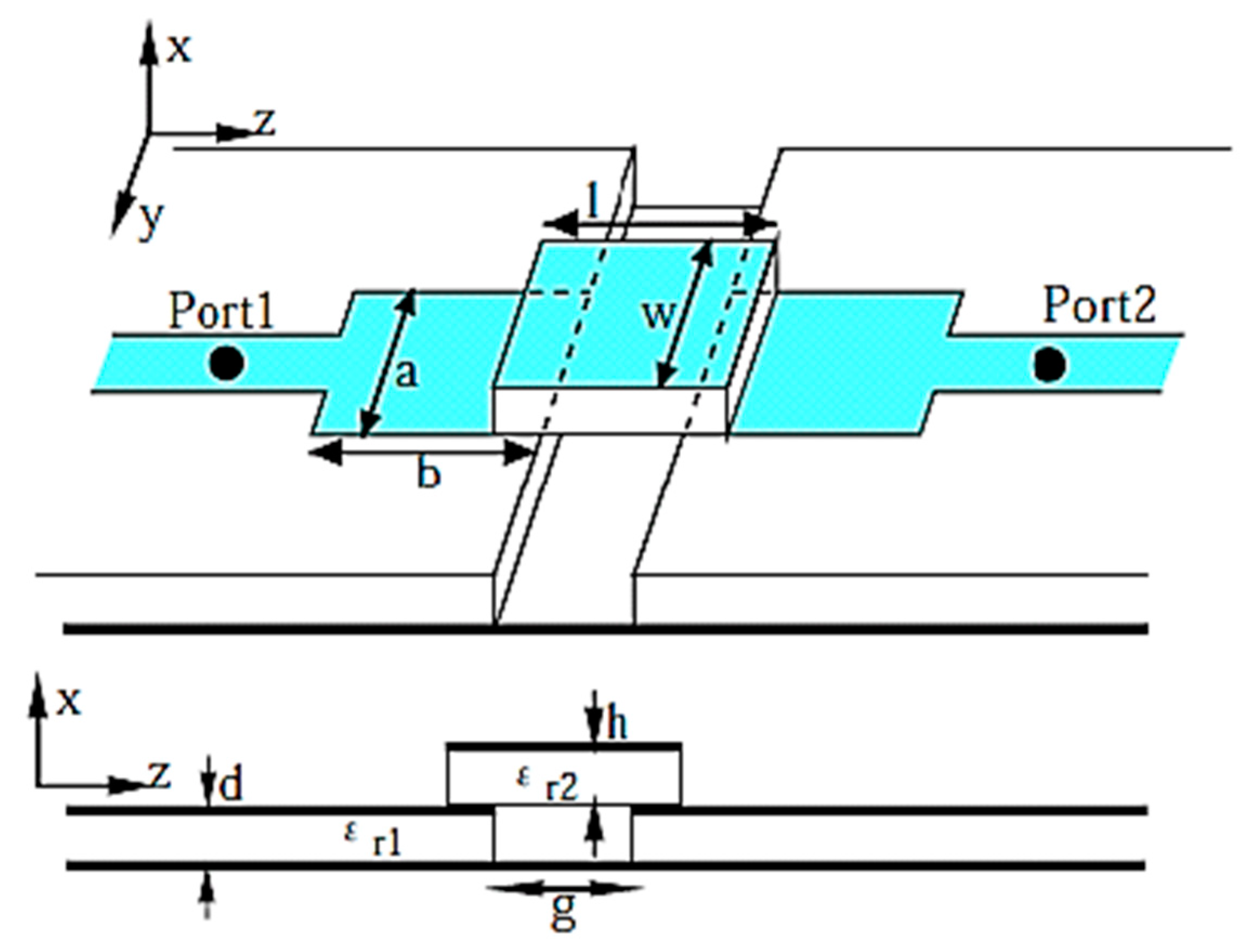
In millimeter-wave band integrated circuit (MMIC) packages and high-frequency band (RF) modules, those crossing orthogonal lines are called ribbon wire bonding, and as the wavelength becomes shorter like millimeter waves, the size of the intersecting parts can be ignored but their effect on transmission cannot be ignored. As a solution to this problem, a ribbon wire interconnector with proximity coupling of resonators arranged in layers has been proposed [6]. As shown in Figure 1, the ribbon wire interconnector has a two-layer structure, and a microstrip resonator with a ground plane is opposed and a coupling resonator is loaded thereon. The lower layer resonator is excited by the microstrip line and propagates the electromagnetically coupled resonators of the upper and lower layers with low loss. As a result, a gap having a width of g is formed, and it is possible to intersect microstrip lines orthogonal to this gap. This structure is applied not only to the ribbon wire interconnector but also to the power divider [25], the phase shifter (DPS) [26], and the like. Its structure is simple, thus having the advantage that printing technology can be used for its production. In the literature [24], the insertion loss is less than 1.25 dB within the band of 33.1% at 6 GHz.
By connecting this structure in cascade, a sheet-like one-dimensional line can be realized. Since this line uses a resonator for the parasitic element, if there is another resonator, that is, an antenna is arranged in the vicinity, strong coupling is obtained and electromagnetic connection with external equipment becomes easy. Furthermore, if the lower layer resonator and the upper layer parasitic element are arranged in a staggered manner, a line having a two-dimensional structure is formed and a sheet-like line is formed. Figure 2 shows the waveguide of one-dimensional structure and its transmission characteristics. It can be seen that the power input from port 1 is efficiently transmitted to port 2.
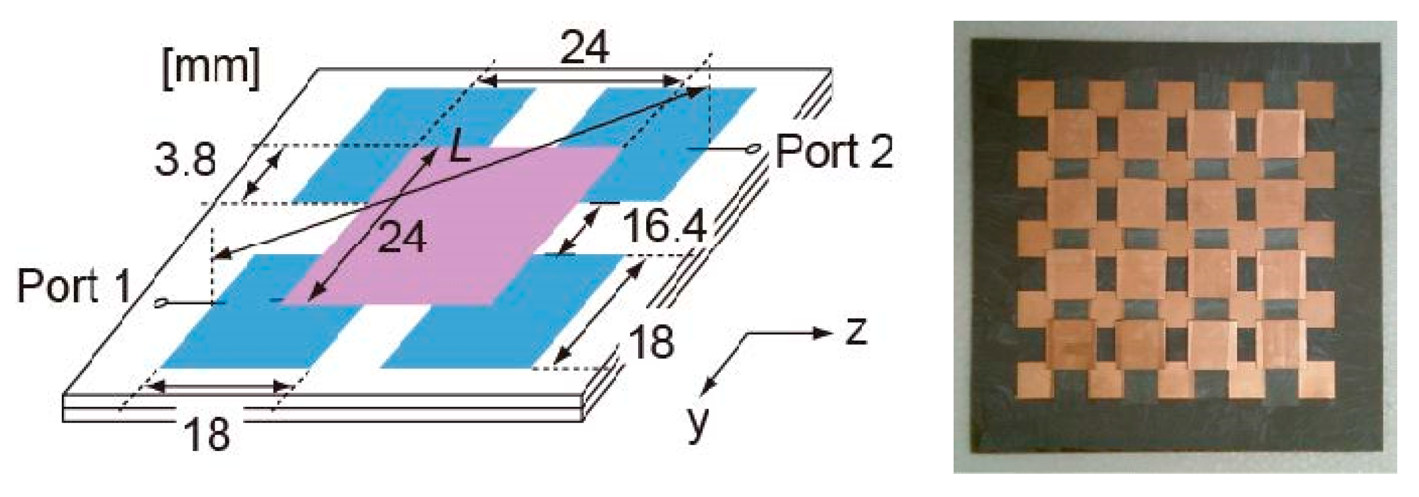
Next, the transmission line with the two-dimensionally arranged structure is a structure in which the upper layer parasitic resonator is arranged at the center of the four resonators on the resonator array layer lined with the ground plate as shown in Figure 3 [10,27,28]. The transmission loss is suppressed by optimizing the dimension of the upper layer parasitic element resonator, and the frequency to be used in the dimension of the lower layer resonator is determined. Although the microstrip resonance length is designed with reference to a half wavelength (/2), as the overlapping area of the lower layer resonator and the parasitic element as viewed from above is wider, the coupling strength is stronger and the transmission loss decreases. Consequently, the distance between adjacent resonators is optimized as a parameter. Also, in order to suppress the occurrence of higher order modes, we have a symmetrical structure.
Figure 4 shows the transmission characteristics when the lower layer resonator designed at 5 GHz is 4 × 4 elements, obtained by simulation using the moment method. In order to clarify the transmission line characteristics, the following is considered:
- the transmission characteristics of only the waveguide provided with the input/output ports 1 and 2 in the lower layer resonator.
- port 1 is connected to the line and the half-wavelength dipole.
- characteristics when the ports 1 and 2 are both half-wavelength dipoles installed on the transmission line.
- the half-wavelength dipole is arranged in the same way as (c).
The above four transmission characteristics are compared when the transmission line is removed.
The broken line in Figure 4 is the transmission loss which is calculated from the inter-port distance in (a) and (c). Since the cylindrical wave propagates in the two-dimensional transmission line, the transmission loss becomes smaller by 10 to 15 dB or more compared to free space. From the results in (b) and (c), the coupling loss between the dipole and the transmission line can be estimated to be 3 dB. It is only necessary for the coupling antenna to match the resonance frequency with the resonator, and it is a great advantage in practical use that a dedicated coupler for coupling the electromagnetic wave to the transmission line is unnecessary. In addition, the distance of the antenna that can be coupled to the transmission line is about λ/4 from the surface of the seat, and electromagnetic waves can be easily excited from the built-in antenna of the small wireless device to the transmission line. The position of the antenna to be coupled can be dealt with at an arbitrary position on the transmission line and is not dependent on the polarization direction of the antenna. Since the coupling is attenuated by more than 30 dB by physically separating the transmission line, even if the transmission lines are adjacent to each other, there is no possibility of mutual coupling, and hence there is an advantage of blocking information between different transmission lines. For use in two frequency bands, it is possible to respond by changing the shape of the lower layer resonator. If a ring resonator as shown in Figure 5 is used as a lower layer, it becomes possible to have dual resonance characteristics and it can be used in two wireless LAN frequency bands of 2.4 GHz and 5 GHz [29].
2.2. Power Transmission by the Sheet-Like Transmission Line
Although the characteristics of the sheet-like waveguide have been explained focusing on information transmission so far, sheet-like waveguides can also be used for power transmission simultaneously with information. First, we show an example in which a model car powered by a rectenna (directly connected to a rectifier circuit) is used as a rail for an electric power supply with a one-dimensional structure line. As shown in Figure 6, a signal source of 2.4 GHz is used as a power source, and electric power is supplied on the one-dimensional line. A rectenna is installed that integrates the antenna and the rectifier circuit 5 mm above the track and the motor of the car is turned with the received electric power. Since it is not possible to receive all the supplied power by the rectenna, it is desirable to install a power recovery device at the end of the line.
In order to efficiently perform power transmission, a patch antenna is used as a power receiving antenna and a full-wave rectifying circuit is incorporated as a rectenna. Although the electric field component in the vicinity of the line is mainly an electric field component parallel to the line, a circularly polarized wave element is used for the power receiving antenna so as to correspond to an arbitrary polarization plane. At this time, the coupling to the rectenna is greatly improved compared with −5 dB compared with the dipole. In the configuration of Figure 6 in which the rectifying circuit is connected to this patch antenna, at the input power of 40 dBm at 2.4 GHz, the output voltage becomes 5.1 V with respect to the load resistance of 3.8 Ω of the motor, and the power transmission efficiency in this system is about 70%. Further improvement in efficiency can be expected by optimizing the rectenna parameters. As described above, it was shown that power transmission by one-dimensional sheet-like transmission line is possible. It is to be noted that electric power transmission using a two-dimensional sheet can be realized in the same manner. In this manner, a method using a sheet-like transmission line that can be used only for devices that are closely coupled is effective. An example of this is in applications such as being able to charge from the access area while riding in an electric car. It is possible to achieve this when transmission line is laid on the road. It is also possible to charge the battery while parking without interfering with the next car by laying mats one by one on the floor of the parking lot.
3. Flexible Transmission Line
Although the sheet-like transmission line can be produced by a dielectric substrate, it can be attached to clothes by using a material with a flexible structure. Figure 7 shows the transmission characteristics when a sheet-like transmission line is constructed using a conductive cloth composed of copper and nickel. It can be seen that the characteristics of the two types of conductive cloths having different compositions are almost equal to each other, as shown in Table 1. The conductive cloth has been fabricated using wrapping machines where the wearable patches were assembled on a flexible sheet which can easily bend with the fabric. The resultant fabric exhibited full metal coverage with good adhesion to the fibers, as well as being conductive and extremely flexible with little effect on its handle and drape properties. In order to make a conductive fabric, cotton was first mercerized followed by immersion in poly (diallyl dimethyl ammonium chloride) solution. Silver nitrate was then reduced on the surface of the fabric which allowed the formation of silver nanoparticles. However, there is a difference between the frequency and the transmission line which is formed in foam form using the copper foil. Since the transmission line composed of the conductive cloth has a flexible structure, it is possible to bend or fold the transmission line.
Figure 8 shows the transmission characteristics when the flexible transmission line is bent. Degradation of transmission characteristics due to bending hardly occurs. Next, a vest-like waveguide that can be worn on a human body is created using this flexible transmission line. As shown in Figure 9, the ground plate and upper- and lower-layer resonators are formed by conductive cloth, and a vest is created with a structure sandwiched between foams. By using this waist cover, it is possible to efficiently perform inter-device communication such as sensors installed near the human body. In particular, when a wireless device is placed in front of and behind the human body, it is difficult to maintain a communication line because the human body exists as a medium with a large loss, but by using this vest (called a smart suit). This situation can be improved. Figure 10 shows the transmission characteristics between the half-wave dipoles placed in front of and behind the human body via the smart suit and the transmission characteristics when both of the two dipoles are arranged on the entire human body. As shown in Figure 10a, when a half wavelength dipole is arranged in front of and back of the human body, the S21 characteristic has a transmission characteristic of about −70dB or less, which is about a noise level. Also, the transmission characteristics when a suit is worn on the human body, and the effectiveness of the smart suit are shown. When the smart suit is worn on the back and front of the human body, then the S21 characteristics have transmission characteristics of about −25dB up to −55dB. This means that the smart suit improves the loss by 45 dB or more as compared with the case when only the antenna is placed on the human body. Figure 10b shows transmission characteristics when the transmitting/receiving antenna is placed on the entire surface of the human body. However, even in this case, the transmission loss is improved by 20 dB or more when a smart suit is used, and its effect is obvious.
4. Conclusion and Future Prospects
The field of sheet waveguides provides a new method of communication. It is conceivable to develop a direction to replace a part of wired communication and a new field expected to utilize wireless communication. In this paper, application examples to sensor/personal/body area network are considered depending on the communication range. There is a rising interest in ubiquitous sensor networks that can be used anytime and anywhere, whether indoors or outdoors. The number of applications, therefore, continues to increase, making it difficult to create a unified network for everything. Because there are various wireless sensor networks depending on applications [30], infrastructure technology supporting these networks is required. For this infrastructure, functions such as providing power wirelessly, location estimation, time synchronization, etc. are required. In outdoor wireless sensor networks such as ecological observation and forest monitoring, these functions can be provided to sensor networks using solar cells, GPS systems, mobile phones, etc. However, in indoor environments, it is possible to synchronize time with mobile phones, but otherwise, it is difficult to achieve these aims at present. In order to build an infrastructure indoors, it has been proposed to embed a sensor as a smart building material in a wall of a planar building and connect a network on the surface [19], and to construct the network, a sheet-like waveguide may be applied. For example, it is possible to supply power to a sensor connected to a sheet by connecting a high-frequency power source to the sheet-like waveguide. Moreover, by combining a plurality of antennas in advance on the seat, the arrival direction can be estimated so that the position of the sensor can be estimated, and time synchronization and the like can be easily realized by communication via a transmission line. As described above, a sheet waveguide is suitable for application as infrastructure for a wireless sensor network. Communications limited to a narrow range can also be performed by the sheet-like waveguide. Wireless LAN is commonly used in offices and the like, but leakage of information outside the office and intrusion from outside the office are problematic and various security measures are being studied. Since many terminals are connected to the access point in the office, it is difficult to guarantee the stability of the connection and the communication speed. In order to solve these problems, data encryption is used for security, and for packet leakage methods using coaxial cables and the like are considered [31]. However, the encryption technology must always be ahead of the decryption technology · hacking, and in fact, methods of breaking the encryption are known and are easily available on the Internet. A method of constructing a wireless LAN system using leaky coaxial has been applied to railway radio such as Shinkansen, radio communication in a tunnel and disaster prevention radio system of an underground shopping mall is also considered. However, in many cases, in the 5 GHz band and the 2.4 GHz band like the wireless LAN, the leakage coaxial loss becomes a problem and realization is difficult. Also, a cable of several tens of meters can be used for applications covering the entire office, but it is not suitable for wireless environments of individuals with high security, that is, for LANs of about several meters.
Since the size of a desk, 1 m to 2 m can be thought of as the range that can be managed by the user, the system that allows communication only to wireless devices close to the sheet-like waveguide can be expected to be applied to wireless LAN with high security. There are abundant uses such as listening to music simply by placing a portable audio terminal and a speaker on the sheet-like waveguide, synchronizing data just by similarly placing a notebook PC, and charging by simply placing a mobile terminal.
As an example, outside the office, medical applications may be considered. It is not desirable to attach a sensor connected to the cable to the body for a long time for testing. By laying a sheet waveguide on the bed, information from sensors installed on the back, for example, can also be transmitted. In the sheet-like waveguide, since the accessible range is limited, there is no problem of interference with other sensors.
Research on Body Centric Networks such as wearable networks and human body communication has been drawing attention recently [32,33]. There is research on wristband type electrodes for human body communication that communicate with people along the body, etc. However, in the high-frequency band such as 2.4 GHz, radiation to the outside of the body is larger than the propagation of electromagnetic waves along the body. In applications where it is permissible to wear a sheet-like waveguide made of wearable material, efficient transmission becomes possible. A smart suit made of conductive cloth is excellent as an auxiliary transmission line of BAN since various sensors can be attached to a human body, meaning power supply and information acquisition from a sensor can be performed at the same time. This becomes a possible means of information transmission for disaster relief and some military applications [34,35].
In addition, by wearing a sheet-like waveguide fabricated from a flexible material in a robot wearing various sensors including GPS, it is possible to remove the cable between the sensors wound around the robot and measure the size of the robot, an application that gives a conceivable degree of freedom of movement. Studies on wearable antennas using conductive fabrics and the like are actively conducted, and the technology can be applied [34,35]. There is also no need to wear an antenna at the bottom of the shoe to take out card-type electronic money, but it is possible to ride a train by stepping on the vicinity of the ticket gate, or an application that charges the card by just standing up.
As described above, various application fields are expected for the wearable waveguide composed of the sheet waveguide and the flexible material, and it is desirable for use in the future.
Author Contributions
All authors contributed equally in this work.
Acknowledgments
This work was supported by the Basic Science Research Program through the National Research Foundation (NRF) of Korea funded by the Ministry of Education (grant number: NRF-2017R1D1A1B03028350).
Conflicts of Interest
The authors declare no conflict of interest.
References
- Vigneshwaran, C.; Alex, Z.C.; Shambavi, K. Design and analysis of spiral wearable antenna. In Proceedings of the International Conference on Gree Computing Communication and Electrical Engineering (ICGCCEE), Coimbatore, India, 6–8 March 2014; pp. 1–4. [Google Scholar]
- Ali, M.; Gentili, G.B.; Salvadore, C.; Toccafondi, A.; Zani, F. Design and analysis of a wearable antenna system for wireless safety applications. In Proceedings of the European Conference on Antennas and Propagation (EuCAP), Lisbon, Portugal, 13–17 April 2015; pp. 1–4. [Google Scholar]
- Saarika, U.; Sharma, P.K.; Sharma, D. A roadmap to the realization of wireless body area networks: A review. In Proceedings of the International Conference on Electrical, Electronics, and Optimization Techniques (ICEEOT), Chennai, India, 3–5 March 2016; pp. 439–443. [Google Scholar]
- Shankar, S.K.; Tomar, A.S. A survey on wireless body area network and electronic-healthcare. In Proceedings of the 2016 IEEE International Conference on Recent Trends in Electronics, Information & Communication Technology (RTEICT), Bangalore, India, 20–21 May 2016; pp. 598–603. [Google Scholar]
- Movassaghi, S.; Abolhasan, M.; Lipman, J.; Smith, D.; Jamalipour, A. Wireless Body Area Networks: A Survey. IEEE Commun. Surv. Tutor. 2014, 16, 1658–1686. [Google Scholar] [CrossRef]
- Cai, F.; Li, Z.; Agar, J.C.; Wong, C.P.; Papapolymerou, J. Novel stretchable electrically conductive composites for tunable RF devices. In Proceedings of the IEEE/MTT-S International Microwave Symposium Digest, Montreal, QC, Canada, 17–22 June 2012; pp. 1–3. [Google Scholar]
- Liu, Q.; Ford, K.L.; Langley, R.; Robinson, A.; Lacour, S. Flexible dipole and monopole antennas. In Proceedings of the 5th European Conference on Antennas and Propagation (EUCAP), Rome, Italy, 11–15 April 2011; pp. 2052–2056. [Google Scholar]
- Klemm, M.; Kovcs, I.Z.; Pedersen, G.F.; Tröster, G. Novel small-size directional antenna for UWB WBANS/WPAN applications. IEEE Trans. Antennas Propag. 2005, 53, 3884–3896. [Google Scholar] [CrossRef]
- Alomainy, A.; Hao, Y.; Parini, C.G.; Hall, P.S. Comparison between two different antennas for UWB on-body propagation measurements. IEEE Antennas Wirel. Propag. Lett. 2005, 4, 31–34. [Google Scholar] [CrossRef]
- Conway, G.A.; Scanlon, W.G.; Orlenius, C.; Walker, C. In situ measurement of UHF wearable antenna radiation efficiency using a reverberation chamber. IEEE Antennas Wirel. Propag. Lett. 2008, 7, 271–274. [Google Scholar] [CrossRef]
- Klemm, M.; Troester, G. Textile UWB antennas for wireless body area networks. IEEE Trans. Antennas Propag. 2006, 54, 3192–3197. [Google Scholar] [CrossRef]
- Seager, R.; Chauraya, A.; Vardaxoglou, Y.; de Maagt, P. Towards a compact low-frequency woven antenna. In Proceedings of the 2009 IEEE Antennas and Propagation Society International Symposium, Charleston, SC, USA, 1–5 June 2009; pp. 1–4. [Google Scholar]
- Kaivanto, E.; Lilja, J.; Berg, M.; Salonen, E.; Salonen, P. Circularly polarized textile antenna for personal satellite communication. In Proceedings of the 4th European Conference on Antennas and Propagation (EuCAP), Barcelona, Spain, 12–16 April 2010; pp. 1–4. [Google Scholar]
- Lilja, J.; Salonen, P.; Kaija, T.; de Maagt, P. Design and manufacturing of robust textile antennas for harsh environments. IEEE Trans. Antennas Propag. 2012, 60, 4130–4140. [Google Scholar] [CrossRef]
- Kaivanto, E.K.; Berg, M.; Salonen, E.; de Maagt, P. Wearable circularly polarized antenna for personal satellite communication and navigation. IEEE Trans. Antennas Propag. 2011, 59, 4490–4496. [Google Scholar] [CrossRef]
- Salonen, P.; Jashoon, K.; Rahmat-Samii, Y. Dualband E-shaped patch wearable textile antenna. In Proceedings of the 2005 IEEE Antennas and Propagation Symposium, Washington, DC, USA, 3–8 July 2005; pp. 466–469. [Google Scholar]
- Hertleer, C.; Tronquo, A.; Rogier, H.; Vallozzi, L.; van Langenhove, L. Aperture-coupled patch antenna for integration into wearable textile systems. IEEE Antennas Wirel. Propag. Lett. 2007, 6, 392–395. [Google Scholar] [CrossRef]
- Minami, M.; Nishizawa, Y.; Hirasawa, K.; Morikawa, H.; Aoyama, T. MAGIC-Surfaces: Magnetically interfaced surfaces for smart space applications. In Proceedings of the 3rd International Conference on Pervasive Computing (Pervasive2005), Munich, Germany, 8–13 May 2005; pp. 59–64. [Google Scholar]
- Balasubramanian, V.; Stranieri, A. A scalable cloud platform for active healthcare monitoring applications. In Proceedings of the IEEE Conference on e-Learning, e-Management, and e-Services (IC3e), Howthorn, VIC, Australia, 10–12 December 2014; pp. 93–98. [Google Scholar]
- Makino, Y.; Minamizawa, K.; Shinoda, H. Sensor Networking Using Two-Dimensional Electromagnetic Wave. In Proceedings of the Sensor Symposium on Sensors, Micromachines, and Applied Systems, Tokyo, Japan, 20–21 October 2005; pp. 83–88. [Google Scholar]
- Zhou, G.D.; Hua, T. Recent Developments on Wireless Sensor Networks Technology for Bridge Health Monitoring. Math. Probl. Eng. 2013, 2013, 947867. [Google Scholar] [CrossRef]
- Shinoda, H.; Makino, Y.; Yamahira, N.; Itai, H. Surface Sensor Network Using Inductive Signal Transmission Layer. In Proceedings of the Fourth International Conference on Networked Sensing System (INSS07), Braunschweig, Germany, 6–8 June 2007; pp. 201–206. [Google Scholar]
- Sage, G.P.L. 3D Printed Waveguide Slot Array Antennas. IEEE Access 2016, 4, 1258–1265. [Google Scholar] [CrossRef]
- Beer, S.; Rusch, C.; Gulan, H.; Gottel, B.; Girma, M.G.; Hasch, J.; Winkler, W.; Debski, W.; Zwick, T. An Integrated 122-GHz Antenna Array with Wire Bond Compensation for SMT Radar Sensors. IEEE Trans. Antennas Propag. 2013, 61, 5976–5983. [Google Scholar] [CrossRef]
- Torabi, Y.; Dadashzadeh, G. A compact 1:15 unequal Wilkinson power divider using A-CRLH coupled lines. Microw. Opt. Technol. Lett. 2018, 60, 117–122. [Google Scholar] [CrossRef]
- Sung, G.J. Broadband 90° phase shifter using two short stubs. In Proceedings of the IEEE Radio and Wireless Symposium (RWS), New Orleans, LA, USA, 10–14 January 2010; pp. 464–467. [Google Scholar]
- Sodre, A.C.; Costa, I.F.D.; Santos, R.A.D.; Filgueiras, H.R.D.; Spadoti, D.H. Waveguide-Based Antennas Arrays for 5G Networks. Int. J. Antennas Propag. 2018, 2018, 5472045. [Google Scholar] [CrossRef]
- Islam, S.S.; Alam, T.; Faruque, M.R.I.; Islam, M.T. Design and analysis of a complementary split ring resonator (CSRR) metamaterial based antenna for wideband application. Sci. Eng. Compos. Mater. 2015, 24, 573–580. [Google Scholar] [CrossRef]
- Khatri, A.; Punjabi, N.; Dhawangale, A.; Mukherji, S. Inexpensive Polyester Sheet Based Waveguides for Detection of Cardiac Biomarker, Myloperoxidase. Proceedia Eng. 2016, 168, 125–128. [Google Scholar] [CrossRef]
- Pei, Z.; Deng, Z.; Yang, B.; Cheng, X. Application-oriented wireless sensor network communication protocols and hardware platforms: A survey. In Proceedings of the IEEE International Conference on Industrial Technology, Chengdu, China, 21–24 April 2008; pp. 1–6. [Google Scholar]
- Morgan, S.P. Prediction of indoor wireless coverage by leaky coaxial using ray tracing. IEEE Trans. Veh. Technol. 1999, 48, 2005–2014. [Google Scholar] [CrossRef]
- Yamamoto, K.; Nishida, Y.; Sasaki, K.; Muramatsu, D.; Koshiji, F. Electromagnetic Field Analysis of Signal Transmission Line and Electrode Contact Conditions in Human Body Communication. Appl. Sci. 2018, 8, 1539. [Google Scholar] [CrossRef]
- Oh, J.; Park, J.; Lee, H.; Nam, S. The electrode structure to reduce channel loss for human body communication using the human body as a transmission medium. In Proceedings of the IEEE Antenna and Propagation Society (AP-S) International Symposium, Honolulu, HI, USA, 9–15 June 2007. [Google Scholar]
- Tanaka, M.; Jang, J.H. Wearable microstrip antenna for satellite communications. IEICE Trans. Commun. 2004, 87, 2066–2071. [Google Scholar]
- Thiel, D.V.; Galehdar, A. Flexible, light-weight antenna at 2.4 GHz for athlete clothing. In Proceedings of the IEEE Antenna and Propagation Society (AP-S) International Symposium, Honolulu, HI, USA, 9–15 June 2007. [Google Scholar]
Figure 1.
Ribbon wire interconnector.

Figure 2.
Sheet-like one-dimensional transmission line. (a) Waveguide structure, (b) Transmission characteristics of the waveguide.
Figure 2.
Sheet-like one-dimensional transmission line. (a) Waveguide structure, (b) Transmission characteristics of the waveguide.

Figure 3.
Sheet-like two-dimensional transmission line.

Figure 4.
Transmission characteristics of the two-dimensional transmission line: The dotted lines show the transmission characteristics in free space.
Figure 4.
Transmission characteristics of the two-dimensional transmission line: The dotted lines show the transmission characteristics in free space.

Figure 5.
Transmission line for the dual-frequency band.

Figure 6.
Power transmission by one-dimensional transmission line.

Figure 7.
Transmission characteristics of the two-dimensional transmission line with a conductive cloth.
Figure 7.
Transmission characteristics of the two-dimensional transmission line with a conductive cloth.

Figure 8.
Transmission characteristics of flexible structure two-dimensional transmission line.
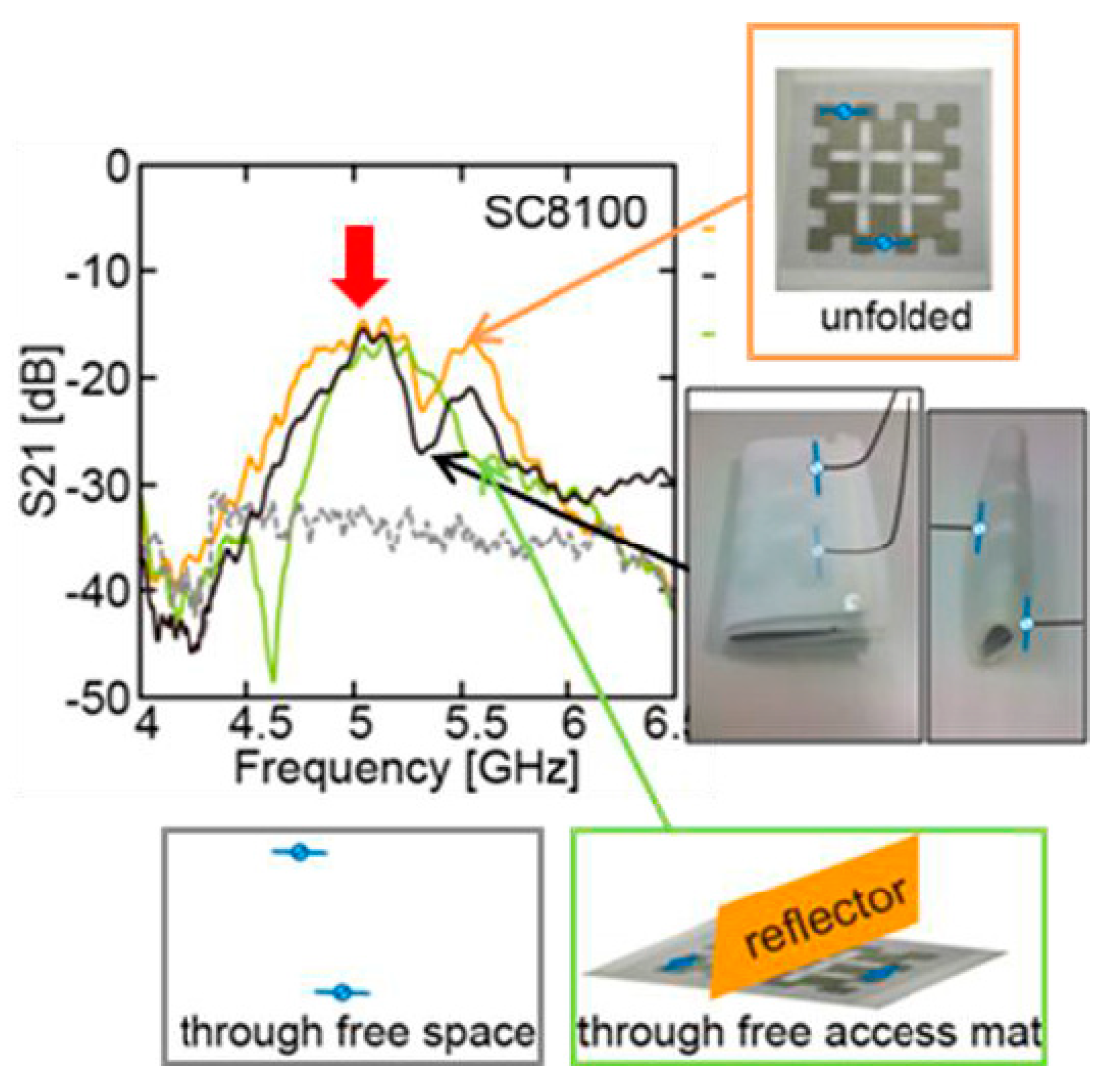
Figure 9.
A vest equipped with a flexible transmission line.
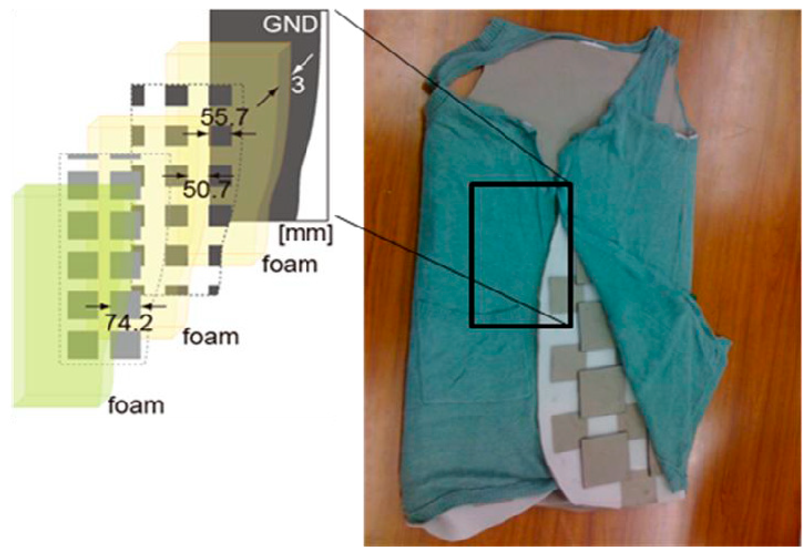
Figure 10.
Transmission characteristics of the smart suit. (a) Transmission characteristics on the back and front of the human body, (b) Transmission characteristics on the front of the human body.
Figure 10.
Transmission characteristics of the smart suit. (a) Transmission characteristics on the back and front of the human body, (b) Transmission characteristics on the front of the human body.


Table 1.
Properties of the Cu and Ni in the proposed conductive cloth.
| Symbol | Thickness (mm) | Electrical Conductivity at 25 °C (m/Ω·mm2) | Thermal Conductivity at 25 °C W/(m·K) | Mass per Unit Surface (g/m2) | Elastic Modulus (kN/mm2) |
|---|---|---|---|---|---|
| Cu | 0.06 | 6.75 | 49 | 55.87 | 145 |
| ST2050 | 0.06 | 6.73 | 45 | 54.31 | 146 |
| SC8100 | 0.04 | 6.81 | 51 | 52.01 | 142 |
© 2018 by the authors. Licensee MDPI, Basel, Switzerland. This article is an open access article distributed under the terms and conditions of the Creative Commons Attribution (CC BY) license (http://creativecommons.org/licenses/by/4.0/).
Share and Cite
MDPI and ACS Style
Saraereh, O.A.; Khan, I.; Lee, B.M.; Al-Bayati, A.K.S. Modeling and Analysis of Wearable Antennas. Electronics 2019, 8, 7. https://doi.org/10.3390/electronics8010007
AMA Style
Saraereh OA, Khan I, Lee BM, Al-Bayati AKS. Modeling and Analysis of Wearable Antennas. Electronics. 2019; 8(1):7. https://doi.org/10.3390/electronics8010007
Chicago/Turabian StyleSaraereh, Omar A., Imran Khan, Byung Moo Lee, and A.K.S. Al-Bayati. 2019. "Modeling and Analysis of Wearable Antennas" Electronics 8, no. 1: 7. https://doi.org/10.3390/electronics8010007
Note that from the first issue of 2016, this journal uses article numbers instead of page numbers. See further details here.