Overview: Types of Lower Limb Exoskeletons
by
 ,
,
Daniel S Pamungkas
1, 
Wahyu Caesarendra
2,3,*,
Hendawan Soebakti
4,
Riska Analia
1 and
Susanto Susanto
1 1
Mechatronics Study Program, Politeknik Negeri Batam 29432, Indonesia
2
Faculty of Integrated Technologies, Universiti Brunei Darussalam, Jalan Tungku Link BE1410, Brunei
3
Department of Mechanical Engineering, Diponegoro University, Jl. Prof.H.Soedarto S.H, Semarang 50275, Indonesia
4
Robotics Study Program, Politeknik Negeri Batam 29432, Indonesia
*
Author to whom correspondence should be addressed.
Electronics 2019, 8(11), 1283; https://doi.org/10.3390/electronics8111283
Submission received: 30 September 2019
/
Revised: 27 October 2019
/
Accepted: 28 October 2019
/
Published: 4 November 2019
(This article belongs to the Special Issue Intelligent Electronic Devices)
Abstract
:Researchers have given attention to lower limb exoskeletons in recent years. Lower limb exoskeletons have been designed, prototype tested through experiments, and even produced. In general, lower limb exoskeletons have two different objectives: (1) rehabilitation and (2) assisting human work activities. Referring to these objectives, researchers have iteratively improved lower limb exoskeleton designs, especially in the location of actuators. Some of these devices use actuators, particularly on hips, ankles or knees of the users. Additionally, other devices employ a combination of actuators on multiple joints. In order to provide information about which actuator location is more suitable; a review study on the design of actuator locations is presented in this paper. The location of actuators is an important factor because it is related to the analysis of the design and the control system. This factor affects the entire lower limb exoskeleton’s performance and functionality. In addition, the disadvantages of several types of lower limb exoskeletons in terms of actuator locations and the challenges of the lower limb exoskeleton in the future are also presented in this paper.
1. Introduction
Nowadays, people work even more strenuously and require stronger and longer lasting muscle movements. However, human muscles have a fatigue limit when doing regular and repetitive activities. To help overcome this fatigue limit, some researchers have suggested that humans use an external wearable device, i.e., an exoskeleton. An exoskeleton, also known as a wearable robotic, is a system that can be worn to help human beings to support and protect parts of their bodies [1]. Such a device has been used for many applications, including enhancing workers when doing their jobs or as medical tools for rehabilitation. In many industries, exoskeletons have been used to increase worker strength for walking on long journeys [2] or lift heavy items [3]. In the medical field, exoskeletons have been used to assist patients who have lost their ability to walk due to spinal cord injuries, stroke, and other trauma [4]. Coenen et al. [5] reported that rehabilitation exoskeletons can improve the quality of exercises during rehabilitation and can accelerate recovery process.
The application of the exoskeleton to the human body can be divided into three locations: (1) throughout the human body [6], (2) at the upper part of human body, such as the torso and arms [7], and (3) at the lower part of the human body, i.e., from the waist down [8]. Various parts of the human body simultaneously play certain functions in supporting movement during walking. However, the lower limbs of the human body have more important roles than the other parts. This is because the lower limbs generate more torque than other parts while walking. This paper reviews a number of existing published papers related to lower limb exoskeletons. However, this paper limits its discussion to the classification of joint motions and types of actuators of the exoskeleton.
The joints in the lower limb of the human body are the hips, knees, and ankles. Each joint has different abilities to move or degrees of freedom (DoF), as shown in more detail in Table 1. The types of lower limb exoskeletons based on joint motions are differentiated into several types based on how the actuators drive the exoskeleton. The actuators can drive just the hips, the knees, or the ankles. In a small number of studies, exoskeletons have multiple actuators to drive a combination of joints. These combinations of actuators are hips and knees, knees and ankles, and all three joints (hips, knees, and ankles).
The source of motion of the actuator can be distinguished by whether it is an active actuator or a passive one. An active exoskeleton is one that uses a power source to activate the actuators. Moreover, an actuator for active motion can be electric, pneumatic [9], or hydraulic [3]. On the other hand, a passive exoskeleton is a device that has no power source. This type of exoskeleton exploits kinematic forces, e.g., by using springs and dampers [10].
This paper is organized as follows. Section 2 presents a brief overview of the biomechanics of the walking process. Section 3 presents a number of exoskeletons grouped according to the locations of the actuators. Section 4 discusses the present state and the future of the lower limb exoskeleton. Finally, Section 5 provides concluding remarks.
2. The Walking Process
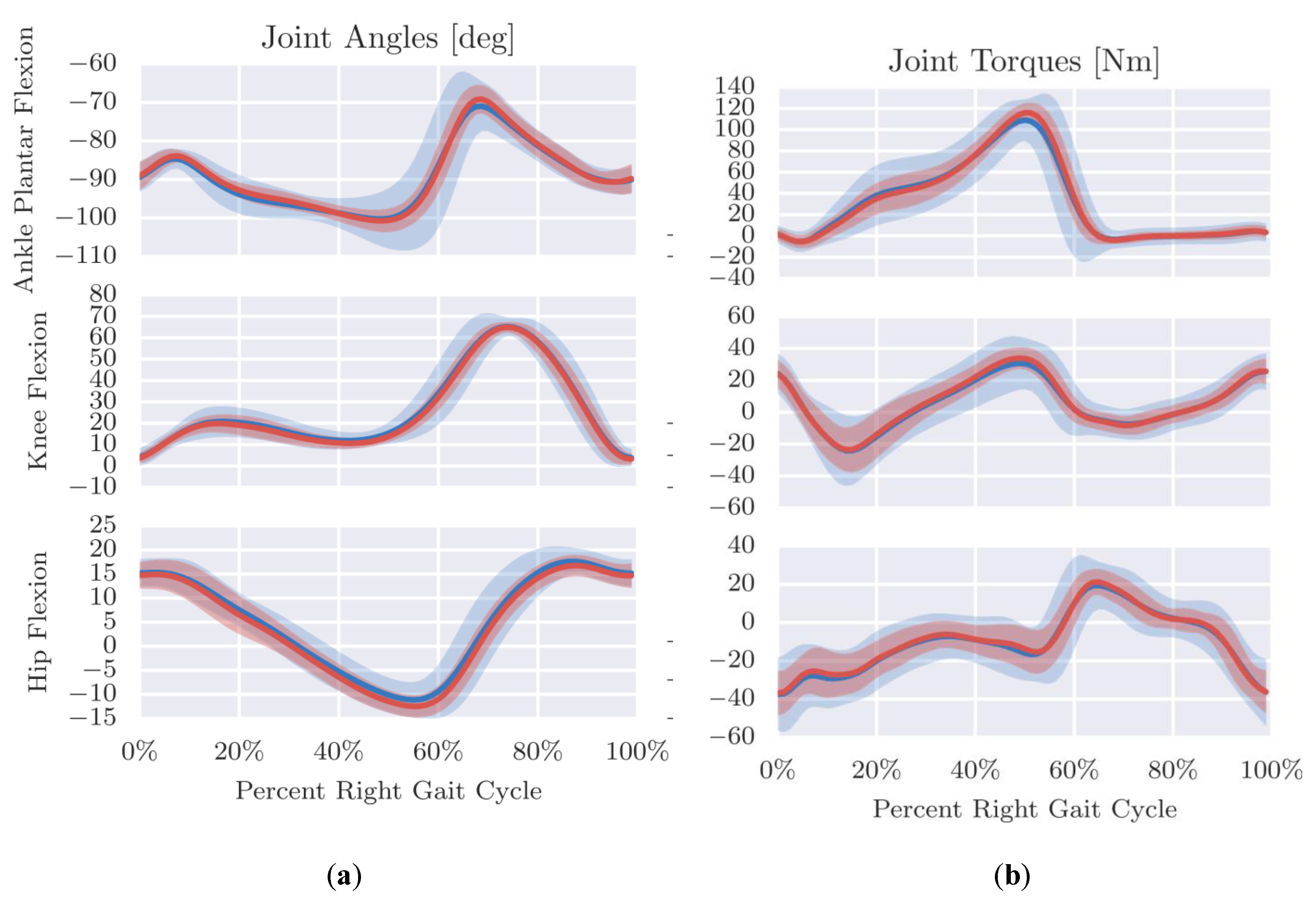
Prior to designing the kinematics of a lower limb exoskeleton, it is necessary to study the cycle of the human walking gait. The human walking gait can be modeled as represented in Figure 1 (adapted from [11]). The human walking gait cycle starts from the right heel contact and ends with the same situation; the steps in the gait cycle are described in Table 2. This cycle determines the movement of the exoskeleton. Moreover, the relationship between the human walking gait cycle with the angle of the hips and the torques needs to be considered. In [12], the authors performed tests on 15 subjects to examine the relationship between angles and torques within the human walking gait cycle. The subjects consisted of 11 males and four females, with heights between 166 and 184 cm. The results of the experiments are presented in Figure 2. The experiment was only conducted for walking on a level surface. The results of the relationships would have differed in the case of other activities, such as running. In addition, angles and torques generated by the human gait also depend on the condition of the surface, e.g., walking on a ramp [13]. The movement of an exoskeleton can be determined by using the relationship between the angles and the cycle gait. Ultimately, torque can be calculated based on the movements of an exoskeleton.
Dominant movement takes place in the sagittal plane (the plane that divides the human body into right and left parts) during the gait. Lower human limbs have three main joints, namely ankles, knees and hips. Therefore, researchers have focused on the movement of exoskeletons in these joints.
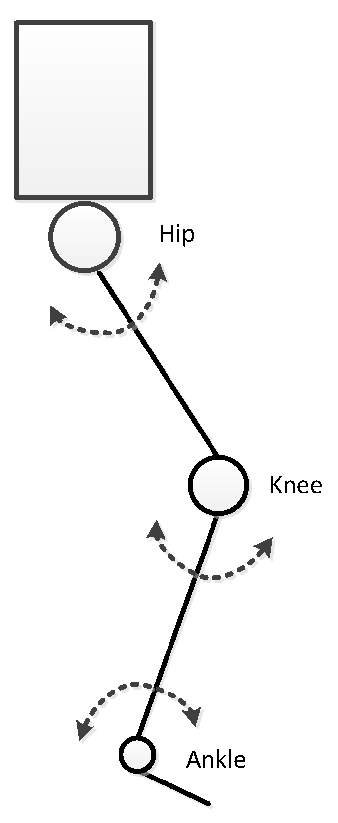
For research purposes, there have been several simplifications of the DoF of lower human limb. Some studies have simplified the lower limbs into seven DoF, i.e., three on hip, one on the knee, and three on the ankle; five DoF, i.e., two on the hip, one on the knee, and two on the ankle; and even only three DoF for the main DoF only, as presented in Figure 3. The main DoF are the flexion (positive direction) and extension (negative direction) movements of the hip, knee and ankle joints. For each hip and ankle, one or two DoF can be added. The other DoF in the hip and ankle are abduction (movement of pulling away from the center of the body) vs. adduction (movement of pushing toward the center of the body) and eversion (movement away from midline of the body) vs. inversion (movement toward the midline of the body). The simplified DoF of the exoskeleton cause a reduction in the ability of the device to be utilized by the user. However, researchers have mainly focused on the basic human movements that are used for daily activities. The various types of locations/joint movements of the actuators of exoskeletons are discussed in Section 3.
3. Joints of the Exoskeleton
This section provides a discussion about the various types of exoskeletons. Exoskeletons are classified by the location of the power sources of the lower exoskeleton. The actuators of the lower exoskeleton are usually placed on the joints of the human. The purpose of this part of the exoskeleton is to move the joint of the user. The actuator can be placed only one joint on each leg, such as the hip, knee or ankle; a combination between two joints (hip and knee, or knee and ankle); or a combination between three joints (hip, knee and ankle).
3.1. Hip Exoskeleton
Hips connect the upper limbs and the lower limbs. Human hips enable their owner to perform the motions of flexion/extension, abduction/adduction, and medial/lateral rotation (three DoF motions). These motions are required for a human to walk or run. Most researchers have placed actuators on the hips of the users for their exoskeletons. Moreover, Lenzi et al. [14] concluded that the hip exoskeleton enables a reduction of hip and ankle muscle activities.
Honda developed an exoskeleton called the Honda Walking Assist [15]. This device has one Direct Current (DC) motor on each hip. The force from the motor is passed to the thigh of the user through the straps, resulting in a light and neat exoskeleton. In another design similar to Honda Walking Assist [15], Giovacchini et al. [16] developed a hip orthotic whose actuator is located near the user’s hips. This exoskeleton helps the user to move their hip in the flexion and extension directions (Figure 4a). Moreover, this wearable robot is equipped with a passive actuator that enables the user to move in the abduction–adduction direction, resulting in user comfort.
The HiBSO (hip ball screw orthosis) exploits a ball screw in each leg for transmitting the force from a DC motor [17]. At the end of the ball screw is a strap that passes the actuation movement to the thigh (see Figure 4b). This structure has other movements beside the flexion/extension action. The HiBSO enables the user to move in the abduction/adduction direction in the hips, while allowing for the rotation of the thigh. Another wearable robot, Powered Hip Exoskeleton or PH-EXOS also added abduction/adduction motions and internal and external rotation [18]. These motions enrich its primary movements, namely flexion/extension, with the abduction and adduction motions being passive actions. The motors are placed on the waist of the user and are connected to the pulley through a Bowden cable, as seen in Figure 4c.
Asbeck et al. [19] constructed an exoskeleton called the Exosuit. They constructed the webbing straps with a geared motor that is carried on the user’s back. These straps are linked to the thigh of the user, as seen in Figure 4d. These straps perform by contracting and expanding on the leg during the heel strike until the terminal stance.
3.2. Knee Exoskeleton
The human knee is an important object of study by researchers, because this part of the human body generates significant torque for walking [12], running [20], and movement from squatting to standing and vice versa [21,22]. Moreover, knees also restrain impact during those activities. Additionally, the position of the knee is between the hip and the ankle. Compared to the hip and ankle, the knee has a more straightforward movement—flexion/extension as well as rotation movements. However, for the sake of simplification, most studies of exoskeletons have modeled only one DoF for the knee exoskeleton, dedicated entirely to moving the knee in the flexion/extension actions.
A soft inflatable cushion is used as the actuator in an exoskeleton [23]. The inflatable part is placed behind the knee of the user. This component allows for the reduction of the weight of the exoskeleton. To inflate and deflate the component, a pneumatic system is used. This exoskeleton is inflated during the swing phase of the walking gait and deflated during the other phases of the walking gait cycle. Figure 5a shows this exoskeleton. Two DC motors are used to actuate two Bowden cables [24]. One of the cables is connected to a strap behind the lower thigh, while another cable is connected to a strap in front of the top of the thigh, as presented in Figure 5b.
Another activity that is often used while working is squatting. Human knees have an essential role in the squatting motion. The squatting action requires a high torque from the knees [21]. Moreover, several activities are required in the squatting movement. However, most wearable robots are not designed for this action. A passive one-DoF knee exoskeleton was developed by Ranaweera et al. [10] to help humans lift loads from the squatted position. This device employed two helical elastic springs on each knee. This component was connected to the pulley disk, which was placed behind the knees of the user. Figure 5c shows the prototype of this exoskeleton. Huang et al. [25] designed an exoskeleton to prevent injury because they observed that the squatting motion makes one susceptible to personal injury. This device can help the user to squat and walk without carrying any load. They utilized a motor and transmitted the torque to the gear and pulley by a flexion cable, as presented in Figure 5d. Meanwhile, an exoskeleton was designed for walking and kneeling. Wang et al. [26] developed a knee exoskeleton actuated with a motor and transmitted to a double pulley on the user’s knee. This configuration helps the user to walk and to assume a kneeling posture. The design of this exoskeleton is presented in Figure 5e.
3.3. Ankle Exoskeleton
According to Figure 2, the ankle has the most significant torque during the walking gait compared to other joints. This has caused most studies to place actuators in the ankle. This joint has four bones in three planar motions (three DoF). However, plantar or dorsiflexion movement is the primary movement during the gait cycle. Some researchers have simplified the motions on their exoskeletons to only one DoF for this main ankle movement.
Mooney and Herr [27] developed a one-DoF exoskeleton, as seen in Figure 6a. This equipment was intended to help the user to walk while carrying a load. This exoskeleton uses a brushless DC motor (BLDC) placed in the shank of the user, while the motor controller and batteries are attached to a vest. The device activates a fiberglass strut to pull the ankle of the user; the struts are connected to the boots. Another design called a soft exosuit was proposed by Asbeck et al. [28]. This equipment’s purpose is to assist the user in walking while carrying a load. Their exoskeleton is actuated by an electric motor; the motor, batteries and controller are placed in a backpack. This motor is connected to a Bowden cable. The purpose of the cable is to pull the heel of the user (see Figure 6b). The cables behave similarly to the human calf muscle. Another exoskeleton was designed by Bai et al. [29]. This device is used for the therapy of subjects suffering from ankle injuries. Figure 6c shows this exoskeleton. An electric motor is mounted in front of the shinbone, while the motor control and batteries are carried on the subject’s waist. The belt is used to transmit the movement of the motor to the gear. This system functions to activate the subject’s ankle. An ankle exoskeleton powered pneumatically was devised by Shorter et al. [9]. The movement of the subject’s ankles is actuated by a rotary pneumatic actuator. This device is attached at the ankle of the user. This exoskeleton utilizes two valves, with the air source placed on the subject’s waist.
Some studies have attempted to add additional DoF of the ankle exoskeleton, such those of Carberry et al. [30], Agrawal et al. [31], and Park et al. [32]. A two-DoF ankle exoskeleton was proposed by Carberry et al. [30]. They enhanced their exoskeleton with eversion/inversion movements. This device is intended for post-stroke rehabilitation. The mechanism of the exoskeleton is pneumatically actuated, with the air source placed separately from the exoskeleton, as shown in Figure 6d. Agrawal et al. [31] developed another two-DoF exoskeleton which has a motion similar to Carberry’s. They combined an active joint with a passive joint. The flexion/extension ankle motions are controlled by a DC servomotor, while the inversion/eversion motions are controlled use a spring and damper mechanism. Three pneumatic synthetic muscles are used to simulate the human leg muscles [32], as seen in Figure 6f. This system enables the user to move their ankle with two DoF using these devices with movements similar to the natural ankle.
3.4. Multiple Joints Exoskeleton
To actuate a joint, more than one muscle that passes through multiple joints may be required. Some studies have utilized more than one actuator to actuate joints in their exoskeletons. The actuators actuate a combinations of joints, namely hip and knee; knee and ankle; and hip, knee and ankle. These multiple joint exoskeletons need to have a more advanced control system than single joint exoskeletons, because the movement of the joints has to be controlled in such a way that results in a harmonious gait. These exoskeletons are discussed in this section.
Some researchers have proposed a knee–ankle, two-DoF exoskeleton for rehabilitation. The National University of Singapore (NUS) developed a device to rehabilitate stroke patients. They used a series elastic actuator (SEA) to actuate the knee and ankle joints [33]. The SEA is a connection between a motor with a serial spring. The actuators are placed between the joint and the thigh or shank of the user, with each actuator using a crank and a connecting rod to move the leg of the user. Figure 7a shows this exoskeleton. The WAKE-up (wearable ankle knee exoskeleton) also utilized an SEA [34]. The actuators are chosen to prevent direct contact between the user and the actuator. To transmit power, a timing belt is used. This device is a modular exoskeleton, which can be worn for single joints or for multiple joints at once.
In 2006, a prototype hip–knee exoskeleton was developed by University of Twente. This exoskeleton is called the LOPES (lower extremity-powered exoskeleton) and is intended as a rehabilitation device [35]. This device has actuators on the hip and knee. This design enables the user to move the hip on the flexion/extension and abduction/adduction directions, as well as the flexion/extension direction on the knee. The actuator is actuated by a motor and transmitted to the SEA using a Bowden cable. The LOPES is shown in Figure 7b. For rehabilitation purposes, the clearance of the foot must be sufficient so that this exoskeleton does not actuate the ankle during the gait.
Another type of combined exoskeleton is the hip, knee and ankle exoskeleton, in which all joints of the user’s lower limb are actuated. In 2004, the University of California developed an exoskeleton called the Berkeley Lower Extremity Exoskeleton (BLEEX) [3]. This exoskeleton is actuated using linear hydraulics and has the ability to provide additional power for carrying heavy loads. The two DoF of the hip are actuated using active actuators, while the rotation of the hip is passively actuated by using springs and elastomers. One motion each is actively actuated in the knee joint and the ankle joint. The BLEEX is shown in Figure 7c. The exoskeleton constructed by the University of Salford is an example of an exoskeleton that uses pneumatic muscle actuators (PMA) [36]. This equipment is intended for paraplegic patient rehabilitation. They equipped their exoskeleton with PMA to actuate the hip with three DoF—only one each for the knee and ankle.
4. Discussion
To achieve the aims of the exoskeletons, these devices are equipped with actuators to amplify human gait and power by actuating on joints. The selection of the joints to actuate depends on the objective of the research. Some studies have been intended for the development of exoskeletons whose joint systems are focused on rehabilitation, e.g., ankle exoskeletons developed for the rehabilitation of ankle injuries [29]. To study how an exoskeleton may help squatting activity, the knee joint has been focused on by some researchers [25]. In another example, to help the user carry a heavy load and walk long distances, some researchers considered an exoskeleton in which all the joints in the device were actuated with powerful actuators [3].
The simplest exoskeletons only use a single DoF for actuating the lower human limb joint. This type of manipulator is lightweight and solid. Moreover, this design has advantages, e.g., it is easy to wear, can be worn by different users, and is comfortable. However, such exoskeletons are not ergonomic. In addition, their use can also lead to injury for users [37]. Furthermore, these devices have a limited ability and are not versatile.
On the other hand, exoskeletons with high DoF resembling human DoF will enable users to walk normally and naturally because the design imitates human anatomy. These designs allow users to easily control their devices; moreover, these users have a high maneuverability. However, high-DoF exoskeletons are complex, costly, and cumbersome. In addition, their construction is challenging to wear.
Some exoskeletons combine active and passive actuators. Active actuators are used for actuating the main DoF, e.g., the flexion/extension motion, while additional movements, which are not too significant to the human gait, use passive actuators. This combination is intended to reduce the weight of the device and also to reduce the cost of production. Even though this design lowers power and the ability to maneuver, it is relatively suitable for rehabilitation, a goal which does not need a high level of maneuverability or power.
Other methods to reduce weight include selecting light and reliable materials, such as carbon fiber composites, and using small active actuators. The power source of the active actuator (e.g., batteries) has significant weight costs, although the weight of components has lessened in recent decades. Non-portable exoskeletons, such as exoskeletons for rehabilitation, can have a power source for active actuators outside the exoskeleton. This can minimize the actual weight of the device.
Active exoskeletons can be pneumatically, hydraulically, or electrically powered. The active pneumatic actuator uses a pressurized air source. This type of actuator has several advantages, namely, a light weight and flexibility similar to the human muscle. A pneumatic ankle exoskeleton weighs below 1 kg [32]. However, pneumatic actuators have limited power and are difficult to control. Hydraulic actuators have high power and stability. A hydraulic actuator is able to generate power up to 1.3 kW to actuate a joint. However, this type of actuator is cumbersome and costly. Electric actuators have the benefit of being controllable. This property can be utilized to allow for precise movements of the exoskeleton. Electric motors are often used for this reason. Power transmission from an electric actuator can be done through various ways, such as using Bowden cables, struts, ball screws or belts. Moreover, several types of electric motors can be used, such as a BLDC. However, the drive from an electric motor sometimes needs a gear system to amplify its power.
In the future, exoskeleton research should develop applicable devices that are lightweight, inexpensive, compact, convenient, durable, and efficient. Thus, research should focus on the design of exoskeletons, the choice of actuators and frames, and the harmonization of exoskeleton movement with the natural human gait. Table 3 presents exoskeletons with their types of actuators.
5. Conclusions
This paper presents a review of current studies focused on prototype lower limb exoskeletons. Some of them have had specific joints actuated, while others have used combinations of actuators to actuate multiple joints. The selection of the placement of the actuators to assist the joints is dependent on the aim of the research. Lower limb exoskeletons with DoF similar to human biomechanics enable users to move more naturally. However, the utilization of multiple DoF is complicated and cumbersome. To reduce the weight of devices, some exoskeletons use passive actuators instead of active ones. Some studies have utilized passive actuators for joints or movements that are not significantly involved in the human gait; however, passive actuators are more challenging to control. In the future, the development of research on exoskeletons is expected to significantly increase. The potential for use of these device is broadening, and in the future, the exoskeleton will have a vital role in daily human activities.
Author Contributions
Conceptualization, D.S.P., R.A., and S.S.; methodology, H.S.; validation, W.C. and D.S.P.; formal analysis, W.C. and H.S.; investigation, W.C., and D.S.P.; resources, W.C., S.S. and R.A.; data curation, W.C.; writing—original draft preparation, W.C. and D.S.P.; writing—review and editing, W.C., D.S.P. and R.S.; visualization, W.C. and D.S.P.; supervision, D.S.P.; project administration, W.C.; funding acquisition, D.S.P., and W.C.
Funding
This research received no external funding.
Acknowledgments
The research for this paper was financially supported by the DRPM KemenristekDikti Indonesia.
Conflicts of Interest
The authors declare that there is no conflict of interest regarding the publication of this paper. The funders had no role in the design of the study; in the collection, analyses, or interpretation of data; in the writing of the manuscript, or in the decision to publish the results.
References
- Dollar, A.M.; Herr, H. Lower extremity exoskeletons and active orthoses: Challenges and state-of-the-art. IEEE Trans. Robot. 2008, 24, 144–158. [Google Scholar] [CrossRef]
- Malcolm, P.; Derave, W.; Galle, S.; de Clercq, D. A Simple Exoskeleton That Assists Plantarflexion Can Reduce the Metabolic Cost of Human Walking. PLoS ONE 2013, 8, e56137. [Google Scholar] [CrossRef] [PubMed]
- Kazerooni, H.; Steger, R.; Huang, L. Hybrid control of the Berkeley Lower Extremity Exoskeleton (BLEEX). Int. J. Robot. Res. 2006, 25, 561–573. [Google Scholar] [CrossRef]
- Banchadit, W.; Temram, A.; Sukwan, T.; Owatchaiyapong, P.; Suthakorn, J. Design and implementation of a new motorized-mechanical exoskeleton based on CGA Patternized Control. In Proceedings of the 2012 IEEE International Conference on Robotics and Biomimetics, ROBIO 2012—Conference Digest, Guangzhou, China, 11–14 December 2012; pp. 1668–1673. [Google Scholar]
- Coenen, P.; van Werven, G.; van Nunen, M.P.M.; van Dieën, J.H.; Gerrits, K.H.L.; Janssen, T.W.J. Robot-assisted walking vs overground walking in stroke patients: an evaluation of muscle activity. J. Rehabil. Med. 2012, 44, 331–337. [Google Scholar] [CrossRef] [PubMed]
- Guizzo, E.; Goldstein, H. The rise of the body bots. IEEE Spectr. 2005, 42, 50–56. [Google Scholar] [CrossRef]
- Hessinger, M.; Pingsmann, M.; Perry, J.C.; Werthschutzky, R.; Kupnik, M. Hybrid position/force control of an upper-limb exoskeleton for assisted drilling. In Proceedings of the IEEE International Conference on Intelligent Robots and Systems, Vancouver, AB, Canada, 24–28 September 2017; Volume 2017, pp. 1824–1829. [Google Scholar]
- Christensen, S.; Bai, S.; Rafique, S.; Isaksson, M.; O’Sullivan, L.; Power, V.; Virk, G.S. AXO-SUIT—A modular full-body exoskeleton for physical assistance. In Mechanisms and Machine Science; Springer: Dordrecht, The Netherlands, 2019; Volume 66, pp. 443–450. [Google Scholar]
- Shorter, K.A.; Kogler, G.F.; Loth, E.; Durfee, W.K.; Hsiao-Wecksler, E.T. A portable powered ankle-foot orthosis for rehabilitation. J. Rehabil. Res. Dev. 2011, 48, 459–472. [Google Scholar] [CrossRef]
- Ranaweera, R.K.P.S.; Gopura, R.A.R.C.; Jayawardena, T.S.S.; Mann, G.K.I. Development of A Passively Powered Knee Exoskeleton for Squat Lifting. J. Robot. Netw. Artif. Life 2018, 5, 45. [Google Scholar] [CrossRef]
- Gait | Joint Structure and Function: A Comprehensive Analysis, 5e | F.A. Davis PT Collection | McGraw-Hill Medical. Available online: https://fadavispt.mhmedical.com/content.aspx?bookid=1862§ionid=136086727 (accessed on 16 September 2019).
- Moore, J.K.; Hnat, S.K.; van den Bogert, A.J. An elaborate data set on human gait and the effect of mechanical perturbations. Peer J. 2015, 3, e918. [Google Scholar] [CrossRef]
- Voloshina, A.S.; Ferris, D.P. Biomechanics and energetics of running on uneven terrain. J. Exp. Biol. 2015, 218, 711–719. [Google Scholar] [CrossRef] [Green Version]
- Lenzi, T.; Carrozza, M.C.; Agrawal, S.K. Powered hip exoskeletons can reduce the user’s hip and ankle muscle activations during walking. IEEE Trans. Neural Syst. Rehabil. Eng. 2013, 21, 938–948. [Google Scholar] [CrossRef]
- Walking Assist Device with Stride Management System | Research paper site of Honda R&D Co., Ltd. Available online: https://www.hondarandd.jp/point.php?pid=122&lang=en (accessed on 5 September 2019).
- Giovacchini, F.; Vannetti, F.; Fantozzi, M.; Cempini, M.; Cortese, M.; Parri, A.; Vitiello, N. A light-weight active orthosis for hip movement assistance. Robot. Auton. Syst. 2015, 73, 123–134. [Google Scholar] [CrossRef]
- Baud, R.; Ortlieb, A.; Olivier, J.; Bouri, M.; Bleuler, H. HIBSO hip exoskeleton: Toward a wearable and autonomous design. Mech. Mach. Sci. 2018, 48, 185–195. [Google Scholar]
- Wu, Q.; Wang, X.; Du, F.; Zhang, X. Design and control of a powered hip exoskeleton for walking assistance. Int. J. Adv. Robot. Syst. 2015, 12, 18. [Google Scholar] [CrossRef]
- Asbeck, A.T.; Schmidt, K.; Walsh, C.J. Soft exosuit for hip assistance. Robot. Auton. Syst. 2015, 73, 102–110. [Google Scholar] [CrossRef]
- Grimmer, M.; Eslamy, M.; Seyfarth, A. Energetic and peak power advantages of series elastic actuators in an actuated prosthetic leg for walking and running. Actuators 2014, 3, 1–19. [Google Scholar] [CrossRef]
- Hirata, R.; Duarte, M. Effect of relative knee position on internal mechanical loading while squatting. Brazilian J. Phys. Ther. 2007, 11, 107–111. [Google Scholar]
- Slater, L.V.; Hart, J.M. The influence of knee alignment on lower extremity kinetics during squats. J. Electromyogr. Kinesiol. 2016, 31, 96–103. [Google Scholar] [CrossRef]
- Sridar, S.; Nguyen, P.H.; Zhu, M.; Lam, Q.P.; Polygerinos, P. Development of a soft-inflatable exosuit for knee rehabilitation. In Proceedings of the IEEE International Conference on Intelligent Robots and Systems, Vancouver, AB, Canada, 24–28 September 2017; pp. 3722–3727. [Google Scholar]
- Witte, K.A.; Fatschel, A.M.; Collins, S.H. Design of a lightweight, tethered, torque-controlled knee exoskeleton. In Proceedings of the IEEE International Conference on Rehabilitation Robotics, London, UK, 17–20 July 2017; pp. 1646–1653. [Google Scholar]
- Yu, S.; Huang, T.H.; Wang, D.; Lynn, B.; Sayd, D.; Silivanov, V.; Su, H. Design and Control of a Quasi-Direct Drive Soft Hybrid Knee Exoskeleton for Injury Prevention during Squatting. arXiv 2019, arXiv:1902.07106. [Google Scholar]
- Wang, J.; Li, X.; Huang, T.H.; Yu, S.; Li, Y.; Chen, T.; Su, H. Comfort-Centered Design of a Lightweight and Backdrivable Knee Exoskeleton. IEEE Robot. Autom. Lett. 2018, 3, 4265–4272. [Google Scholar] [CrossRef]
- Mooney, L.M.; Herr, H.M. Biomechanical walking mechanisms underlying the metabolic reduction caused by an autonomous exoskeleton. J. Neuroeng. Rehabil. 2016, 13, 4. [Google Scholar] [CrossRef]
- Asbeck, A.T.; de Rossi, S.M.M.; Holt, K.G.; Walsh, C. A Biologically Inspired Soft Exosuit for Walking Assistance. Int. J. Robot. Res. 2015, 34, 744–762. [Google Scholar] [CrossRef]
- Bai, Y.; Gao, X.; Zhao, J.; Jin, F.; Dai, F.; Lv, Y. A portable ankle-foot rehabilitation orthosis powered by electric motor. Open Mech. Eng. J. 2015, 9, 982–991. [Google Scholar] [CrossRef]
- Carberry, J.; Hinchly, G.; Buckerfield, J.; Tayler, E.; Burton, T.; Madgwick, S.; Vaidyanathan, R. Parametric design of an active ankle foot orthosis with passive compliance. In Proceedings of the IEEE Symposium on Computer-Based Medical Systems, Bristol, UK, 27–30 June 2011. [Google Scholar]
- Agrawal, A.; Banala, S.K.; Agrawal, S.K.; Binder-Macleod, S.A. Design of a two degree-of-freedom ankle-foot orthosis for robotic rehabilitation. In Proceedings of the 2005 IEEE 9th International Conference on Rehabilitation Robotics, Chicago, IL, USA, 28 June–1 July 2005; Volume 2005, pp. 41–44. [Google Scholar]
- Park, Y.L.; Chen, B.R.; Young, D.; Stirling, L.; Wood, R.J.; Goldfield, E.; Nagpal, R. Bio-inspired active soft orthotic device for ankle foot pathologies. In Proceedings of the 2011 IEEE/RSJ International Conference on Intelligent Robots and Systems, Francisco, CA, USA, 25–30 September 2011; pp. 4488–4495. [Google Scholar]
- Chen, G.; Qi, P.; Guo, Z.; Yu, H. Mechanical design and evaluation of a compact portable knee-ankle-foot robot for gait rehabilitation. Mech. Mach. Theory 2016, 103, 51–64. [Google Scholar] [CrossRef]
- Rossi, S.; Patane, F.; del Sette, F.; Cappa, P. WAKE-up: A wearable ankle knee exoskeleton. In Proceedings of the 5th IEEE RAS/EMBS International Conference on Biomedical Robotics and Biomechatronics, São Paulo, Brazil, 12–15 August 2014; pp. 504–507. [Google Scholar]
- Veneman, J.F.; Kruidhof, R.; Hekman, E.E.G.; Ekkelenkamp, R.; van Asseldonk, E.H.F.; van der Kooij, H. Design and evaluation of the LOPES exoskeleton robot for interactive gait rehabilitation. IEEE Trans. Neural Syst. Rehabil. Eng. 2007, 15, 379–386. [Google Scholar] [CrossRef]
- Costa, N.; Caldwell, D.G. Control of a biomimetic ‘soft-actuated’ 10DoF lower body exoskeleton. In Proceedings of the First IEEE/RAS-EMBS International Conference on Biomedical Robotics and Biomechatronics, Pisa, Italy, 20–22 February 2006; Volume 2006, pp. 495–501. [Google Scholar]
- Wang, D.; Lee, K.M.; Guo, J.; Yang, C.J. Adaptive knee joint exoskeleton based on biological geometries. IEEE/ASME Trans. Mechatron. 2014, 19, 1268–1278. [Google Scholar] [CrossRef]
Figure 1.
Human walking gait cycle (adapted from [11]).
Figure 1.
Human walking gait cycle (adapted from [11]).

Figure 2.
(a) Angles of joints and (b) torques of the joint versus the gait cycle (adapted from [12]).
Figure 2.
(a) Angles of joints and (b) torques of the joint versus the gait cycle (adapted from [12]).

Figure 3.
The dominant movements of the human walking gait.

Figure 4.
(a) exoskeleton developed by Giovacchini et al. [16]; (b) HiBSO (hip ball screw orthosis) [17]; (c) PH-EXOS [18]; (d) Exosuit [19].

Figure 5.
Knee exoskeletons using (a) an inflatable actuator [23], (b) a Bowden cable put in the front and back of the leg [24], (c) springs [10], (d) a DC motor and pulley [25], (e) double pulleys [26].

Figure 6.
One-DoF ankle exoskeleton using: (a) DC motor and struts [27]; (b) motor and Bowden cable [28]; (c) DC motor and belt [29]; (d) two-DoF with active actuators [30]; and (e) two-DoF active pneumatic actuators [32].

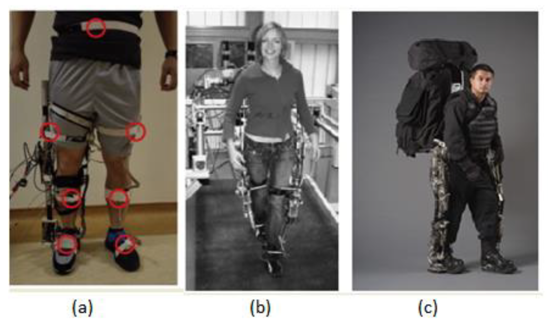
Figure 7.
Multiple joints exoskeletons: (a) the National University of Singapore (NUS) exoskeleton [33]; (b) the lower extremity-powered exoskeleton (LOPES) (all lower limb joints) [35]; and (c) the Berkeley Lower Extremity Exoskeleton BLEEX [3].


Table 1.
Degrees of freedom (DoF) of each joint in the lower limb.
| No | Joints | DoF | Movement |
|---|---|---|---|
| 1 | Hips | 3 | Flexion–extension |
| Abduction–adduction | |||
| Internal–external rotation | |||
| 2 | Knees | 2 | Flexion–extension |
| rotation | |||
| 3 | Ankles | 3 | plantar flexion–dorsiflexion |
| Abduction–adduction | |||
| Eversion–inversion |
Table 2.
Gait cycle position.
| No | Right Leg | Left Leg |
|---|---|---|
| 1 | Heel strike | Pre swing |
| 2 | Loading response | Toe off |
| 3 | Mid Stance | Mid Swing |
| 4 | Terminal Stance | Terminal Swing |
| 5 | Pre swing | Heel strike |
| 6 | Toe off | Loading response |
| 7 | Mid Swing | Mid Stance |
| 8 | Terminal Swing | Terminal Stance |
Table 3.
Actuators in joints of lower limb exoskeletons.
| No | Name/Institution | Joint | DoF | Actuator | Type of Actuator | Weight (kg) |
|---|---|---|---|---|---|---|
| 1 | Honda Walking Assist [15] | Hip | 1 | Active flexion–extension | DC motor | 2.7 |
| 2 | Exoskeleton/The BioRobotics Institute, Scuola Superiore Sant’Anna [16] | Hip | 2 | Active flexion–extension Passive abduction–adduction | DC motor (SEA) carbon fiber linkage | 8.5 |
| 3 | HIPSO [17] | Hip | 2 | Active flexion–extension Passive abduction–adduction | DC Motor ball-bearing | 9.5 |
| 4 | PH-EXOS [18] | Hip | 3 | Active flexion–extension Passive abduction–adduction and internal–external rotation | AC motor mechanical structure | n/a |
| 5 | Hip exosuit/Harvard University [19] | Hip | 1 | Active flexion–extension | DC motor | n/a |
| 6 | Soft inflatable exosuit [23] | Knee | 1 | Active flexion–extension | Pneumatics | 0.16 |
| 7 | Knee Exo/Carnegie Mellon University [24] | Knee | 1 | Active flexion–extension | DC motor | 0.76 |
| 8 | University of Moratuwa, Katubedd [10] | Knee | 1 | Passive flexion–extension | Spring | n/a |
| 9 | Soft hybrid EXO/The City University of New York [25] | Knee | 1 | Active flexion–extension | DC motor | n/a |
| 10 | The City University of New York [26] | Knee | 1 | Active flexion–extension | DC motor | 3.2 |
| 11 | MIT ankle exoskeleton [27] | Ankle | 1 | Active flexion–dorsiflexion | DC motor | 4 |
| 12 | Knee soft exosuit/Harvard University [28] | Ankle | 1 | Active flexion–dorsiflexion | DC motor | 12.15 |
| 13 | Beijing Institute of Technology [29] | Ankle | 1 | Active flexion–dorsiflexion | DC motor | n/a |
| 14 | University of Illinois [9] | Ankle | 1 | Active flexion–dorsiflexion | Pneumatics | n/a |
| 15 | University of Bristol [30] | Ankle | 2 | Active flexion–dorsiflexion | Pneumatics | n/a |
| Active Inversion–eversion | Pneumatics | |||||
| 16 | University of Delaware [31] | Ankle | 2 | Active flexion–dorsiflexion | DC motor | n/a |
| Passive Inversion–eversion | Spring and damper | |||||
| 17 | Harvard University [32] | Ankle | 2 | Active flexion–dorsiflexion | Pneumatics | 0.95 |
| Active Inversion–eversion | Pneumatics | |||||
| 18 | National University of Singapore [33] | Knee– ankle | 2 | Active knee flexion–extension | DC motor | n/a |
| Active ankle flexion–dorsiflexion | DC motor | |||||
| 19 | WAKE-up [34] | Knee– ankle | 2 | Active knee flexion–extension | DC motor | 2.5 |
| Active ankle flexion–dorsiflexion | DC motor | |||||
| 20 | LOPES [35] | Hip– ankle | 3 | Active Hip Flexion–extension | DC motor | n/a |
| Active hip abduction–adduction | DC motor | |||||
| Active knee flexion–extension | DC motor | |||||
| 21 | BLEEX [3] | Hip– Knee– ankle | 5 | Active hip Flexion–extension | Hydraulic | 14 |
| Active hip Abduction–adduction | Hydraulic | |||||
| Passive hip rotation | Spring | |||||
| Active knee Flexion–extension | Hydraulic | |||||
| Active ankle flexion–dorsiflexion | Hydraulic | |||||
| 22 | University of Salford [36] | Hip– Knee– ankle | 5 | Active hip Flexion–extension | Pneumatic | 12 |
| Active hip Abduction–adduction | Pneumatic | |||||
| Passive hip rotation | Pneumatic | |||||
| Active knee Flexion–extension | Pneumatic | |||||
| Active ankle flexion–dorsiflexion | Pneumatic |
© 2019 by the authors. Licensee MDPI, Basel, Switzerland. This article is an open access article distributed under the terms and conditions of the Creative Commons Attribution (CC BY) license (http://creativecommons.org/licenses/by/4.0/).
Share and Cite
MDPI and ACS Style
Pamungkas, D.S.; Caesarendra, W.; Soebakti, H.; Analia, R.; Susanto, S. Overview: Types of Lower Limb Exoskeletons. Electronics 2019, 8, 1283. https://doi.org/10.3390/electronics8111283
AMA Style
Pamungkas DS, Caesarendra W, Soebakti H, Analia R, Susanto S. Overview: Types of Lower Limb Exoskeletons. Electronics. 2019; 8(11):1283. https://doi.org/10.3390/electronics8111283
Chicago/Turabian StylePamungkas, Daniel S, Wahyu Caesarendra, Hendawan Soebakti, Riska Analia, and Susanto Susanto. 2019. "Overview: Types of Lower Limb Exoskeletons" Electronics 8, no. 11: 1283. https://doi.org/10.3390/electronics8111283
Note that from the first issue of 2016, this journal uses article numbers instead of page numbers. See further details here.