A Sequential RFID System for Robust Communication with Underground Carbon Steel Pipes in Oil and Gas Applications

Electrical and Computer Engineering, University of Calgary, Calgary, AB T2N 1N4, Canada
*
Author to whom correspondence should be addressed.
Electronics 2019, 8(12), 1374; https://doi.org/10.3390/electronics8121374
Submission received: 22 August 2019
/
Revised: 18 October 2019
/
Accepted: 24 October 2019
/
Published: 20 November 2019
(This article belongs to the Special Issue Advanced RFID Technology and Applications)
Abstract
:The world’s oil and gas is transported using a network of steel pipelines most of which lie underground. The length of this network in the US/Canada alone is 3.5 million kilometers. Keeping track of pipes in such a network for pipeline-health monitoring, maintenance, and logistics is an acute problem faced by pipeline-operators. Recently, radio-frequency-identification tags (RFIDs) have been proposed for tracking pipelines and even for monitoring pipeline health with additional built-in sensors. Low-cost RFID tags are wirelessly powered and battery-less. However, RFIDs do not function optimally in the presence of magnetic carbon steel pipes that are prevalent in the industry. High-frequency wireless signals also attenuate rapidly through wet soils. In this research, the use of passive RFID sensor platforms for interrogating buried pipes up to 1.25 m deep in the LF bands is proposed. Using magnetic-induction-based communication, a test-comparison between conventional full/half duplex (FDX/HDX) and sequential (SEQ) RFID schemes is detailed. Wireless measurements in the presence of an industry-standard ASTM A-53 carbon-steel pipe show a SEQ RFID offering better immunity against magnetic proximity effects of the pipe’s wall with an 8.3 dB (x6.8) improvement over a FDX/HDX RFID operating under similar conditions over a distance of 80–125 cm at which pipes are typically buried.
Keywords:
RFID; tag; magnetic; inductive; communication; sequential; duplex; microcontroller; power management; pipeline; leak; sensing1. Introduction
The majority of oil and gas in North America are transported using a network of buried pipelines that is about 3.5 million kilometers long. The vast majority of it buried 1 m below the ground [1,2]. Keeping track of pipes in such a network for pipeline-health monitoring, maintenance, and logistics is an acute problem faced by pipeline-operators. This tracking is needed to prevent pipeline leaks of hydrocarbons and other transported material that are commonly caused by pipeline buckles and corrosion thereby preventing contamination of surrounding soil, water, and air. Current methods to interrogate buried pipelines involve expensive digs or use of in-line inspection (ILI) tools called PIGS. However, it is estimated that roughly one third of the world’s pipes are not PIG-able [2]. Recently, the use of wireless sensor networks have been proposed for real-time tracking and monitoring of pipelines, which while being lower cost have to overcome significant physical challenges due to the ground and metallic pipe material.
1.1. Underground Communication Challenges
The attenuation of wireless signals through soil is a well-known phenomenon that is further aggravated by the presence of moisture and snow. It has been shown that as frequency increases so does the path loss through materials [3]. However, it has also been shown by the same author that magnetic fields while experiencing higher propagation loss with distance are more immune to material or medium losses including soil and moisture compared to electromagnetic fields [4].
The research presented in [5] show the effects of different soil compositions and frequencies on EM attenuation. Increasing the volumetric water content from 20% to 80% increased the attenuation by a factor of four for EM fields. However, magnetic fields are not affected in the same way since the relative permeability of soil, water, and clay are all very close to 1 (same as air) [6]. Materially speaking, magnetic fields are only affected while passing through magnetic materials such as iron (magnetic permeability = 5000) and carbon steel (magnetic permeability = 100) [7]. For these reasons, magnetic inductive coupling (MI) is primarily used for underground communication since they are impervious to soil and humidity.
1.2. Communication Challenges Due to Magnetic Interference
While magnetic fields are impervious to soil and water at lower frequencies, carbon steel pipes do interfere with magnetic fields with varying effects at different frequencies. Close to 90% of existing pipelines used for transporting oil and gas are made of carbon steel with a magnetic permeability of 100 [8]. Magnetic metals such as carbon steel can interfere with magnetic fields in three ways [8,9,10]. Magnetic fields produced by a coil in the vicinity of external metals induces eddy currents in the metal, which produce an opposing field to counteract the magnetic field produced by the coil. This opposing field also impedes the flow of charge carriers in the coil. The net result is an increase in the AC resistance of the coil, which is also known as magnetic proximity effect. Depending on the frequency, distance, and magnetic permeability or nature of the external metal, the metal can also alter the magnetic flux density given out by the magnetic field producing coil, which can alter the coil inductance thereby detuning it [10]. Any radio-frequency-identification tags (RFID) system for buried pipelines has to overcome these issues due to the effects of carbon steel pipe walls and ground effects.
1.3. Wireless/RFIDs for Pipelines
In [11,12,13,14], Akyildiz et al. introduce an underground wireless sensor network (UWSN) that uses multiple coils wrapped around a buried pipe to relay data and power using magnetic induction. This research proposes using the pipe as part of the medium or MI wave guide to relay data and power through the coils at longer distance. While theoretical analysis has been covered in these studies, a working prototype has not been presented. In [15] a battery-powered wireless-sensor mote containing an eRA400TRS 433 MHz transceiver is used to communicate data from force sensors and leak-sensing thermal sensors from an above-ground pipe. While this research demonstrates the usefulness of wireless sensor networks (WSNs) to detecting water leaks from above-ground pipes, their communication range in underground environments would be severely attenuated due to the use of 433 MHz EM fields. Moreover, periodic battery replacement in buried sensors would be logistically expensive.
Another wireless sensor mote using LF (125 kHz) magnetic induction from a buried battery-powered transmitter is presented in [16]. With the help of a large coil antenna measuring 4 m by 4 m on the surface, a ground-penetration communication range of 12 m is achieved through buried black schist ore. This research shows the potential of magnetic fields or magnetic induction communication in achieving longer ground-penetrating range albeit with buried batteries that present logistical and environmental problems.
In [17], the authors present a wireless, battery-free, passive RFID-based sensor that uses inter-digitated capacitors and a 100 MHz passive communication system to communicate strain information from a pipe section. While the battery-less system does offer logistical advantages, the communication frequency of 100 MHz could only attain a range of 1 cm through sand. For pipeline/ground penetrating applications, wireless propagation losses and interference due to ground and metallic pipes tend to be the main challenge compared to wireless collisions/traffic prevalent in over-the-air environments dense RFID environments found in retail and freight industries.
1.4. Commercial RFIDs for Pipelines
There are a few commercial RFID systems for pipeline asset tracking. 3M offers RFID markers that use MI in the 0.6–200 kHz band with a ground-penetrating range of 1.8 m to save/relay information such as placement date, application type, etc. [18]. These do not work in the presence of metal pipes. There are also quite a few companies that offer sub one-meter RFID asset marking products that use conventional ultra-high frequency (UHF) with an 860–960 MHz range. These will generally detune and attenuate in the presence of metal pipes, soil, and snow, but may still function over a short range. A French company called RYB offers an RFID marker that they claim can be attached to all types of pipes (cast-iron, polyethylene, steel, concrete, polyvinyl chloride), and buried up to 1.5 m [19]. They use the conventional 13.56 MHz protocol. All the above products are for marking and asset identification that require much lower voltage (≤1 V) on the tag-side. This makes them incapable for powering heavier loads, such as sensors, microcontrollers, etc., needing 3 V or higher to monitor pipeline health.
The two commercial RFIDs are for marking pipelines incapable of wireless powering and interrogating sensors. The studies cited in Section 1.3 are primarily implemented to serve as sensor platforms or motes to communicate info about the health of a pipe section. Primary challenges with RFID-based sensor platforms are generating large supply voltages to power sensors in fewer tags during downlink powering and relaying its data back to the surface reader during uplink. Underground sensor platforms using TDMA or comparable RFID schemes to interrogate multiple tags currently do not exist since the main challenge in such environments is one of wireless link with the metal pipes and infrastructure more so than wireless traffic as this and other studies cited in Section 1.3 show. Furthermore, measurements done in this research show that the overall packet rate and charge time is much slower due to lowering of the SNR in a metal heavy pipe environment further limiting the use of TDMA schemes common in over-the-air RFID standards for pipeline applications. Furthermore, adding a TDMA scheme for multiple tags per pipe section would slow down the overall interrogation of a whole pipe length due to slow read-outs from a single pipe section along the pipe length.
1.5. Overview of Proposed Design
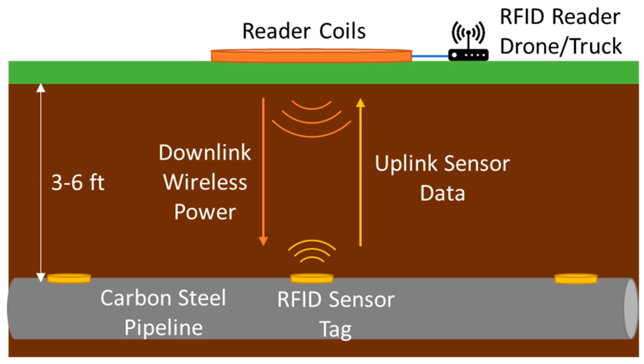
We propose a ground-penetrating, sequential-based RFID sensor platform capable of generating high tag voltages (≥3 V) at penetration depths of over three feet to allow powering of temperature, pressure/strain, and moisture sensors typically used for monitoring oil pipelines as shown in Figure 1. The novelty of our sensor platform is the use of a custom sequential RFID communication scheme that offers many advantages over conventional MI and UHF RFID systems. These advantages include better immunity to carbon-steel pipes, capability to power heavier microprocessor loads for localized intelligence, and a greater read range. The proposed platform works by placing RFID sensor tags along the pipe which are read periodically from the surface by the reader. This method allows for monitoring of pipeline defects at lower costs compared to currently used techniques such as In-line-inspection tools/PIGS. The communication protocols and system schematics are designed to reduce the detuning effects of metal seen by conventional RFID platforms. Our solution combines the higher range of currently available methods from 3 m and RYB, with the sensor abilities of [15,16,17] while remaining passive (battery-less). A comparison to other research is shown in Table 1.
1.6. Overview of RFID Communication
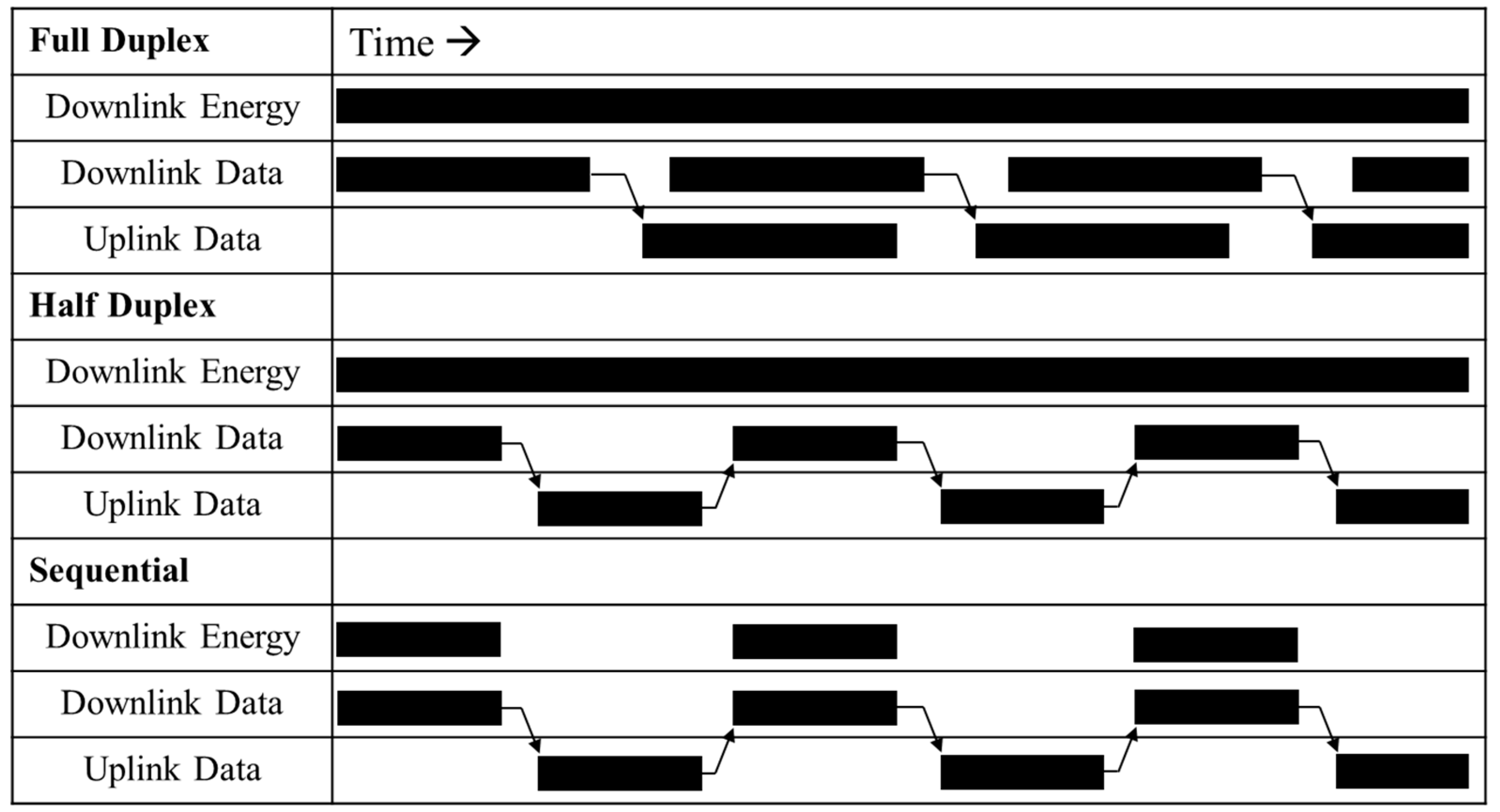
There are two basic communication procedures which RFIDs systems follow: Full/half duplex systems (FDX/HDX) or sequential systems (SEQ). In both systems the RFID tags are wirelessly powered by the RFID reader. However, in the conventional full/half duplex system, the tag responds to the reader while the reader is transmitting through EM or magnetic backscatter done via load modulation on the tag side. For full duplex, the reader and tag can transmit data at the same time, while for half duplex the reader and tag communicate asynchronously. The readers EM field remains on to transmit power from reader to tag even during data communications as shown in Figure 2. Most conventional RFIDs that operate under ISO 18000, 15693, and 14223 standards in the 860–925 MHz, 13.56 MHz, and 125 kHz bands use full/half duplex communication procedures.
A sequential system is when the reader supplies downlink power to the tag that is stored as energy similar to a wireless power transfer (WPT) or semi-passive tag system. This stored energy is used to then transmit data to the reader in a follow-up uplink cycle during which the reader is not transmitting power but only receiving data similar to a near-field-communication system (NFC). This timing is shown in Figure 2. The downlink data portion is optional as this is not always necessary since it is mainly used to write identification (ID) numbers or reprogram the tag software. The system designed in this paper employs this procedure. Reasons for why this implementation was used and why it has a significant advantage when attached to pipelines is also detailed below. Most RFIDs are based on FDX/HDX as it usually has a higher throughput than SEQ and does not require as much capacitor storage or power management since power is continuously transmitted.
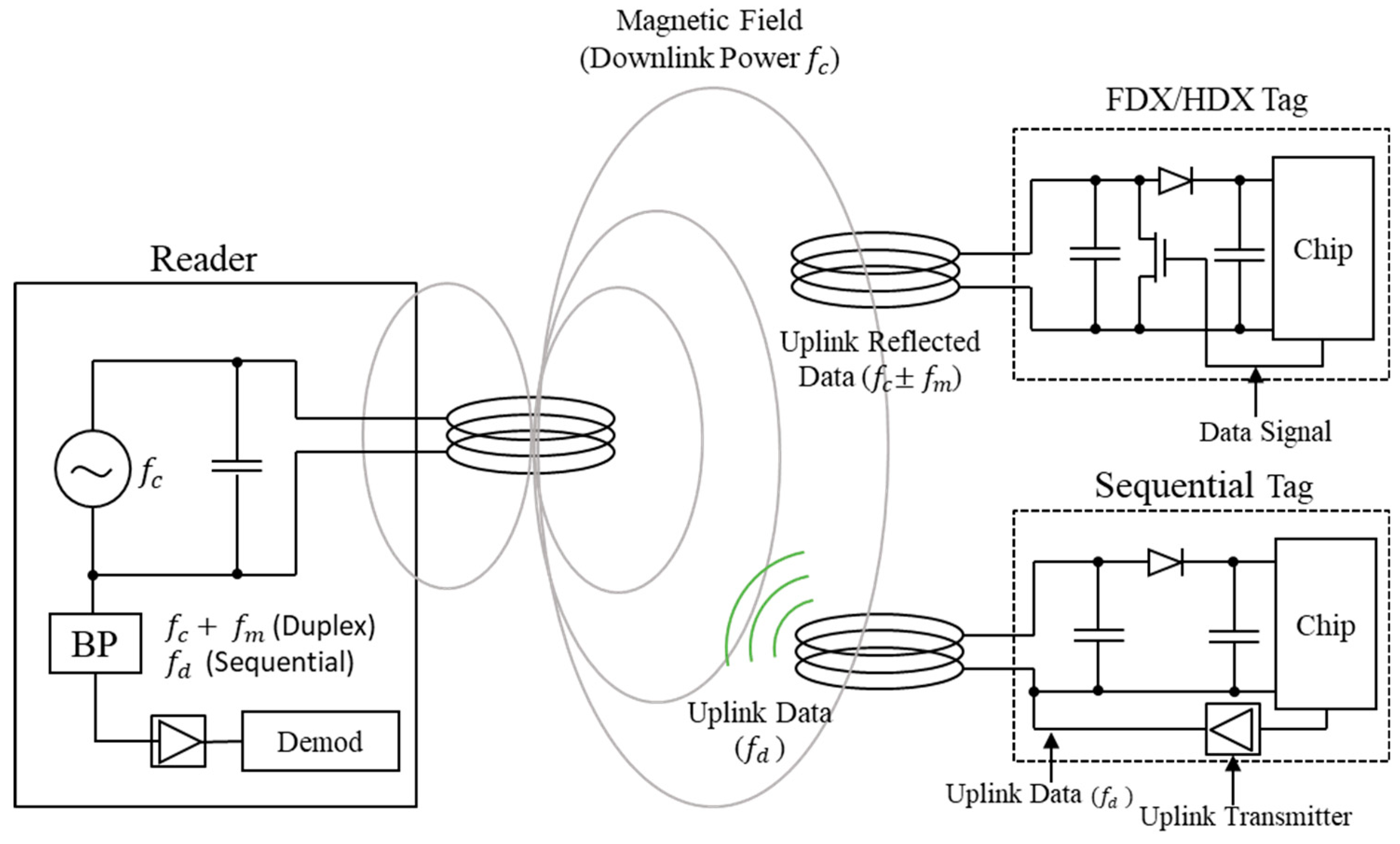
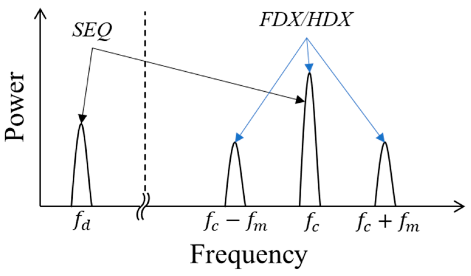
FDX/HDX RFIDs use load modulation of the antenna/coil on the tag side to encode and send uplink data back to the reader. Load modulation is done by switching between matched and short loads attached to the tag antenna as shown in Figure 3. When used in HF and LF bands (100 kHz–13.56 MHz), FDX/HDX RFIDs use magnetic induction as the physical field interaction between reader and tag, which is also referred as magnetic backscatter in some RFID literature. When used in the UHF bands (860–925 MHz, 2.4 GHz), FDX/HDX RFIDs use EM backscatter as the physical field interaction. When two coils are placed in the near-field, they act like a loosely coupled transformer. In FDX/HDX RFIDS during downlink transmission at a frequency fc, periodically changing the antenna load impedance on the tag side with a frequency fm detunes the antenna on the reader side as well. This changing antenna load impedance modulates the downlink carrier (at frequency fc) and results in the generation of sideband data (an amplitude modulated signal across the reader antenna) as shown by the FDX/HDX spectrum in Figure 4 [20]. On the other hand in SEQ RFIDs, during downlink transmission of power at a frequency fc, the wireless power is only converted and stored with no modulations carried out by the tag. During uplink the stored wireless power is used to transmit data at an independent frequency fd during a subsequent time slot. The spectrum for SEQ is shown in Figure 4. Because the RFID tag must remain powered when the reader’s downlink powering is off, the storage capacitor needs to be much larger, and a dedicated transmit circuit must be implemented. However, having the downlink power off during uplink data transmission helps prevent carrier leakage between the transmit and receive sides in the reader, thereby reducing noise in uplink data reception. As shown in Figure 3, the SEQ tag contains an uplink transmitter. The charge pump/rectifier, logic circuit, and tuned tag coil perform similar functions in both RFID systems.
Conventionally, RFIDs using near-field magnetic inductions have operated in LF and HF bands for different applications as shown in [20]. HF bands (13.56 MHz) typically offer faster data rates compared to LF bands (~58–120 kHz) and also induce higher open circuit output voltage (Voc) on the tag coil albeit at the cost of higher current consumption by the tag. This can be seen from Equation (1) that shows a Voc increasingly linearly with the carrier frequency (fc). However, the tag’s input voltage (Vin–pk) is the coil open circuit voltage divided by the coil’s AC resistance (Rcoil) and input impedance of the tag’s rectifying and voltage-multiplying charge pump circuit (Rtag) as shown in Equation (2a). The coil’s AC resistance is given by Equation (2b) below and shows an increase by a factor of 12 from LF to HF bands [21]. The coil’s AC resistance (Rcoil) is further increased due to proximity effects of the carbon steel pipe, which was characterized using a BK Precision 895 impedance analyzer for a 0.07 m radius and 55-turn coil made using 435 strands of 40 AWG (strand radius a = 0.08 mm) Copper Litz wire (Copper magnetic permeability µ, conductivity σ) that was used in the tag designs. Preliminary measurements are shown in Figure 5 and show the AC resistance of the coil increase roughly linearly by approximately 0.5 ohms per kHz due to magnetic proximity effects of the pipe. Furthermore, real and complex magnetic permeability of most soil, sand with varying moisture at frequencies in the LF bands is 1 and 0, which is the same as that of air [6]. Magnetic fields in the LF bands therefore do not experience additional propagation losses due to ground soil and moisture like higher frequency electric and magnetic fields. As a result for proposed research, the downlink power transfer was carried out at an intermediate carrier frequency of 105 kHz (fc) and the data modulation was carried out at 16 kHz (fd, fm) that can be conveniently generated using a Microcontroller’s internal RC oscillator in both RFID tag systems.
| Voc: Open Circuit voltage induced across tag coil due to current Ir in reader coil | |
| µ: Magnetic permeability of medium (air) | fc: Frequency of downlink transmission (105 kHz) |
| Nr: Number of turns in reader coil | Nt: Number of turns in tag coil |
| Ir: Current in reader coil (A) | At: Area of tag coil |
| rr: Radius of reader coil (m) | d: Distance between tag and reader (m) |
2. Sequential (SEQ) and FDX/HDX RFID System Designs
2.1. SEQ Tag Circuit System
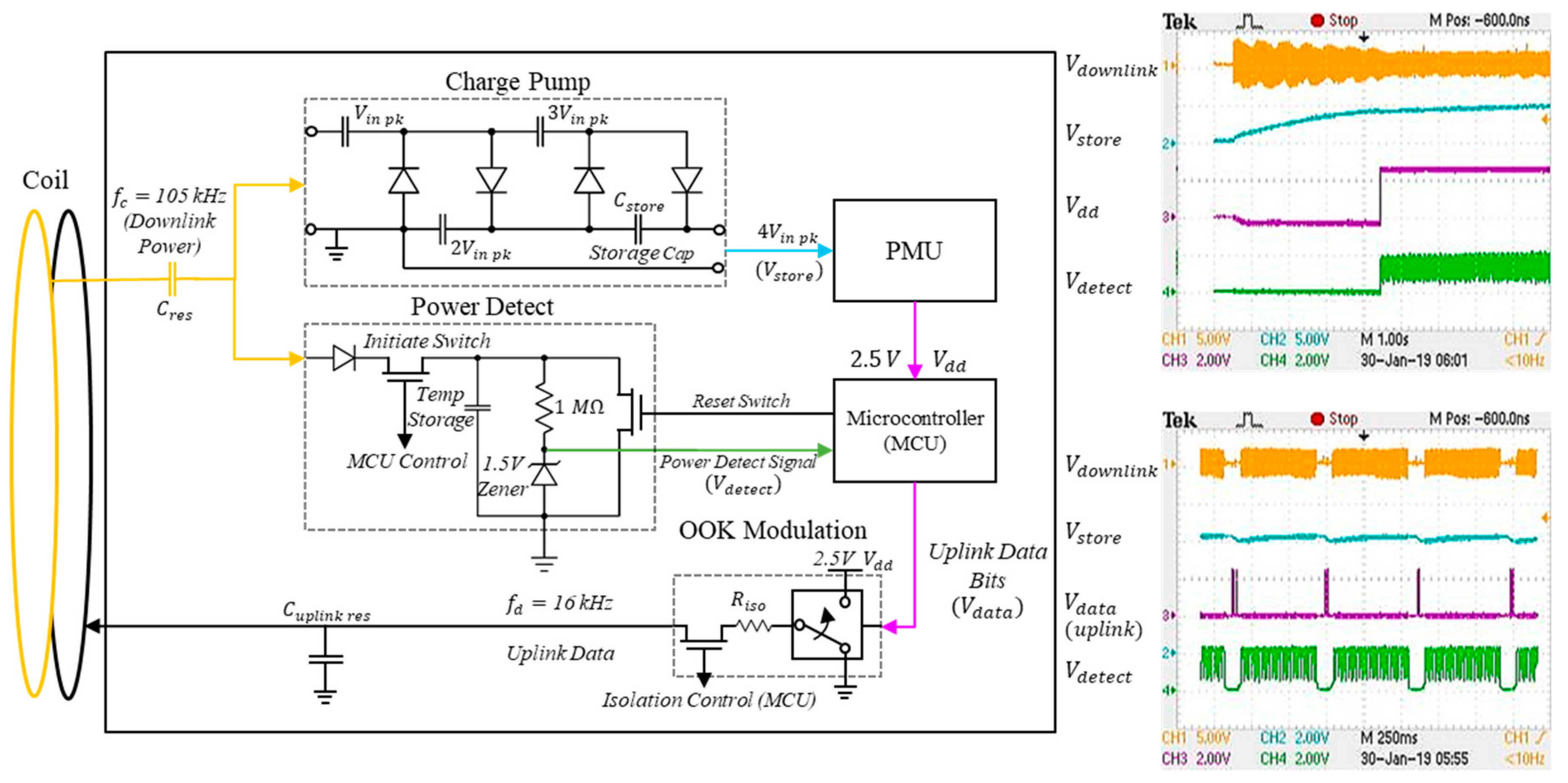
In order to study the effects of buried carbon steel pipes on RFID communication systems, a sequential RFID platform comprised of a reader and sensor tag was designed. The SEQ tag system is shown in Figure 6. The tag was designed to power heavier loads like a microprocessor and sensors for pipeline health monitoring for limited duty cycles using just the downlink power signal from the reader stored in an energy storage capacitor. The tag was designed to power itself from a 105 kHz (fc) downlink power signal received from the reader, and communicate a 16 kHz (fd) on-off keyed (OOK) uplink data signal. Although designed for structural health monitoring of pipelines, it can be applied to other applications where a battery-free sensor is required, usually in an environment where running wires is not an option.
All reader and tag coils were wound using multi-strand Litz wire which limits losses due to skin-depth effects and lowers AC resistance at high frequency of current through the coils [9]. All coils including in the SEQ tag were built using Litz 435/40, which is made up of 435 individually isolated strands of 40 AWG wire. The 40 AWG wire allows the coils to carry currents up to a maximum frequency of 2.9 MHz without significant skin depth losses. The SEQ tag coil was designed with 55 turns and a radius of 0.07 m. With a reader coil made up using 14 turns and a radius of 0.4 m, the wireless downlink power signal is expected to generate an open circuit voltage of between 7.17 V and 2.2 V across the tag coil at burial depths of between three and five feet, respectively, using Equation (1). With a properly designed and matched tag circuit, these open circuit voltages are expected to generate coil voltages of between 3.5 and 1.1 V over the same depths at the tag’s charge pump input (Vin–pk) using Equation (2).
The downlink signal is fed into a series resonating capacitor optimally chosen to tune out the tag coil’s inductance at 105 kHz. It is then split into a charge-pump circuit and a power-detect circuit. The charge pump, shown in the ’Charge Pump’ block from Figure 6, is a voltage quadrupling rectifier that is designed to quadruple and rectify the tag coil voltage (Vin–pk) of between 3.5 and 1.1 V to a higher 14 and 4.4 V at different buried depths. This quadrupled voltage (Vstore) is stored as energy across a large 2 mF energy-storage capacitor (Cstore). The energy-storage capacitor is used to store the downlink power as energy and supply power to the microcontroller through a power management unit (PMU) for uplink communication and any future 1.8–3 V sensing devices for limited duty cycles. The PMU is a commercially available LTC 3588 chip which controls DC voltage output to the micro-controller (MCU) with hysteresis. For our application, the PMU was configured to output 2.5 V DC (Vdd) when an input of 4.04 V or higher (Vstore) is present across Cstore, and deactivate the output when Vstore falls below 2.87 V. This hysteresis allows the MCU and any future sensor load to consume regulated current from Cstore without entering a never-ending reset state that is an issue with capacitor-powered loads. This is a necessity for cold start operation of the tag as no batteries or external power is available.
For a conjugately impedance-matched tag design, the open-circuit tag coil voltage (Voc = 7.17 V) is expected to yield a 3.58 V tag input voltage, which the charge pump quadruples to 14.34 V at the PMU input at a range of three feet (1 m) based on Equation (1). In practice, the higher resistance of the parallel charge pump and power-detect circuits compared to the coil’s resistance results in a higher tag input voltage and consequently higher PMU input voltage. As a result, the tag and PMU input were measured to be slightly higher at 3.95 V and 15.8 V, respectively, at a range of three feet (1 m).
The 2.5 V PMU output (Vdd) supplies voltage to a PIC24FKA101 MCU which was chosen for its ultra-low power modes 30 µW while running with a 2.5 V supply, and as little as 20 nW while in deep sleep [22]. Having an MCU in the SEQ tag allows the tag to implement a variety of sensors unlike conventional tags which only include serial ID numbers and other basic information. It also allows for localized intelligence where the MCU can process and filter the data before sending it to the reader.
The power-detect block in Figure 6, also known as an ’end of burst detector,’ is used by the tag to determine when the reader has finished sending power and is awaiting data. The MCU initiates power detection and monitors the downlink power signal through a small temporary storage capacitor voltage (Vdetect) charged by the downlink signal. The uplink data communication by the MCU is only initiated in the absence of downlink power transmission marked by drain of charge across this temporary capacitor or a low Vdetect. Initiate and reset switches are used by the MCU to minimize interference of the power-detect circuit with the tag coil during downlink power transmission and charge build up across the charge pump. Current consumption of the power-detect block is minimized by the use of 1.5 V Zener diodes along with the 1 MΩ large resistor and use of deep sleep mode by the MCU during downlink power transmission or completion of uplink communication and sensor processing.
The OOK modulation circuit was implemented using two MCU-controlled FET-based switches and supplied by the 2.5 V supply output from the PMU. The isolation control switch prevents interference from the uplink circuitry to the downlink power transmission, and also with the isolation resistor (Riso) prevents the rapid draining of the energy storage capacitor through the coil during uplink data transmission. The second double-throw switch toggles the uplink data coil between the 2.5 V supply (Vdd) and ground in sync with the uplink data generated by the MCU. The measured voltages at these different sub-blocks of the tag circuitry at cold start during downlink power transmission and uplink data transmission are also shown in Figure 6.
2.2. FDX/HDX Tag Circuit System
Conventional FDX/HDX RFID tags are widely used and commercially available. For the purpose of this research a comparable FDX/HDX communication tag was designed similar to the conventional tag design shown in Figure 3 which uses load modulation. The same coils were used for the SEQ and FDX/HDX RFID tag and reader systems with the tuning capacitor optimized for each RFID’s uplink data frequency. The carrier and data frequencies during the downlink carrier and uplink data transmission were set at 105 kHz (fc) and 16 kHz (fm, fd), respectively. To eliminate potential losses in the downlink power’s AC/DC conversion, the FDX/HDX tags were externally powered with 2.5 V during communication comparison tests. An MCU-controlled low-loss switch was used to toggle a resonating capacitor across the tag coil in sync with the data.
2.3. RFID Reader
A common reader to test both the RFID systems on pipelines was implemented using RF equipment and discrete commercial off-the-shelf components as shown in Figure 7. The reader uses an Agilent 33120 function generator and an Accel TS 250 current amplifier with a 0.4 m radius 14 turn coil to generate a 6 A peak waveform for downlink wireless power transmission to the tag. The uplink data that is received from the tag is amplified by a voltage amplifier and then demodulated and decoded using an Arduino Due 32 bit processor with a 86 MHz clock and a built-in 12 bit ADC (ADC speed 1000 ksps). The uplink data is also alternatively fed into a Tektronics RSA 306B spectrum analyzer to study the spectral characteristics of the uplink data signal received from the SEQ and FDX/HDX tags with and without the pipe. The downlink power transmission and uplink data reception are controlled by the Arduino Due process with a USB-connected computer used for data processing. The tag and reader prototypes were built using discrete parts and assembled using breadboards and surface mount (SMT) adapters. The measurement setup of the reader and tag in the vicinity of the pipe is shown in Figure 8. The tags were attached directly to the pipe.
3. Theoretical Analysis
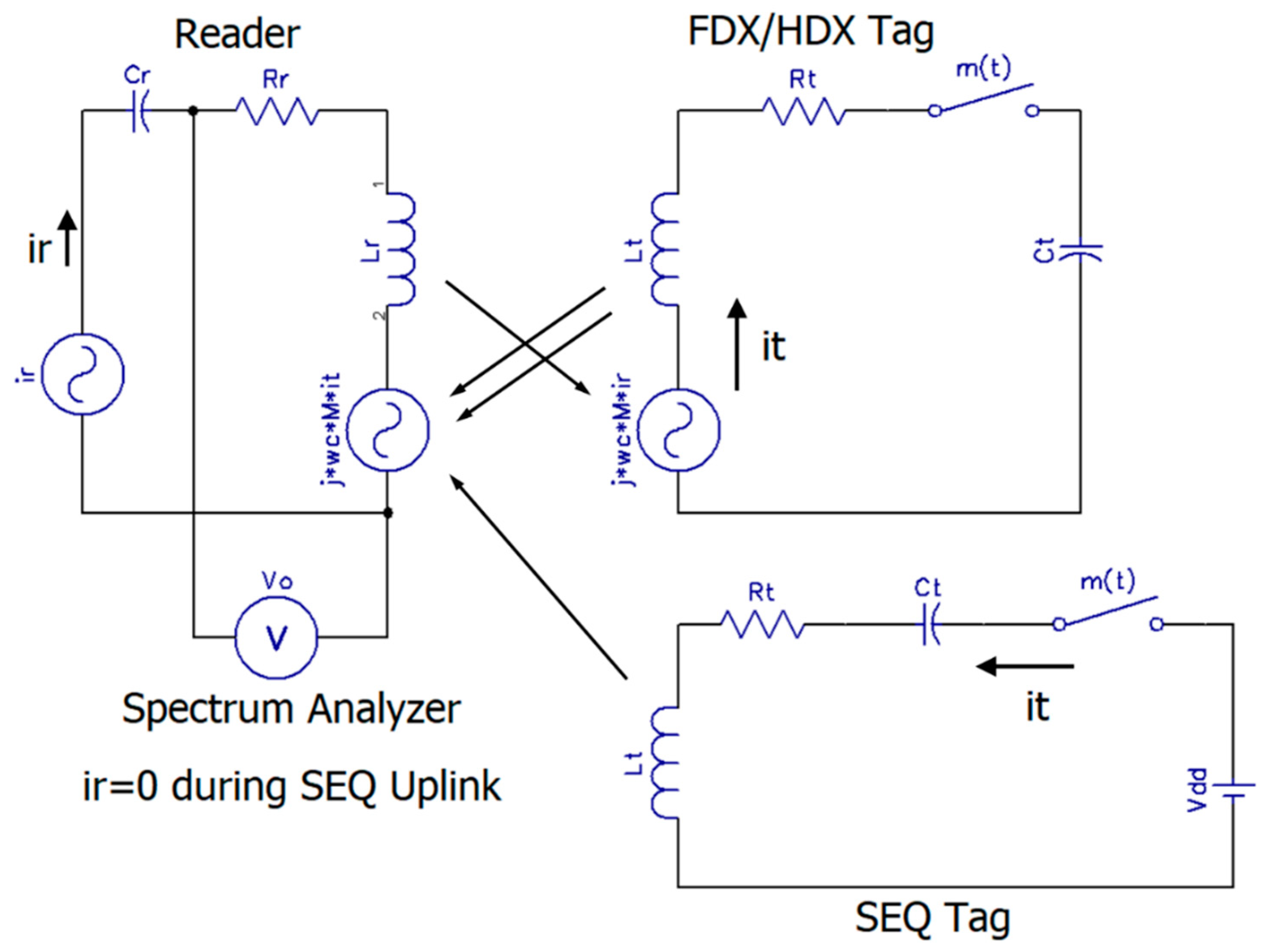
The equivalent circuits for the FDX/HDX and SEQ RFID tags without the pipe during uplink data transmission are shown in Figure 9. For the FDX/HDX RFID tag, the data-modulated voltage output (Vo) received on the reader side is given by Equation (3) where Vc represents the fixed carrier voltage across the reader coil (Zr, Rr, and Lr) and Vm represents the data-modulated voltage induced on the reader side due to the load modulation carried out by the tag in sync with the data bits [20]. Zr represents the total reader coil impedance comprised of a large coil inductance (Lr) and small AC resistance (Rr). ‘M’ represents the mutual inductance between the reader and tag coils during the uplink data transmission. ‘M’ depends on the reader and tag coil inductances (Lr and Lt) and coupling co-efficient k, which varies with distance/orientation as shown in Equation (4).
The current in the tag (it) at the higher carrier frequency fc is induced by the reader current (ir). It (it) is further modulated with data bits using the PIC microcontroller in the tag using on-off-keying at a data frequency fm as shown in Equation (5). The second term in Equation (5) represents the Fourier series co-efficient of m(t), i.e., the binary pulse modulation of the tag current by the PIC.
For tag coil with inductance Lr that is tuned with a resonating capacitor Ct at a resonating frequency around fc, the DC component and higher order harmonics are filtered out to give the tag current expression shown in Equation (6)
Substituting Equation (6) in Equation (3) and writing the mutual inductance in terms of the reader and tag coil inductances yields the data/tag-load modulated output voltage read on the reader side as shown in Equation (7). Zr is the total reader coil impedance, which is mostly inductive.
For the SEQ RFID system, the tag powered with the energy storage capacitor Cstore and PMU output voltage (Vdd) acts like a near-field transmitting source, and the reader acts like its receiver as shown in Figure 9 and Figure 10. For a properly tuned tag coil, the coil’s inductance and series resonating capacitance filter out the higher order odd harmonics and DC component produced by the binary pulse modulated data signal m(t). Its final output voltage read on the reader side (Vo) is given by Equation (8) for the case where the impedance of the measurement probe (Ro) is higher than the reader coil resistance (Rr) [20].
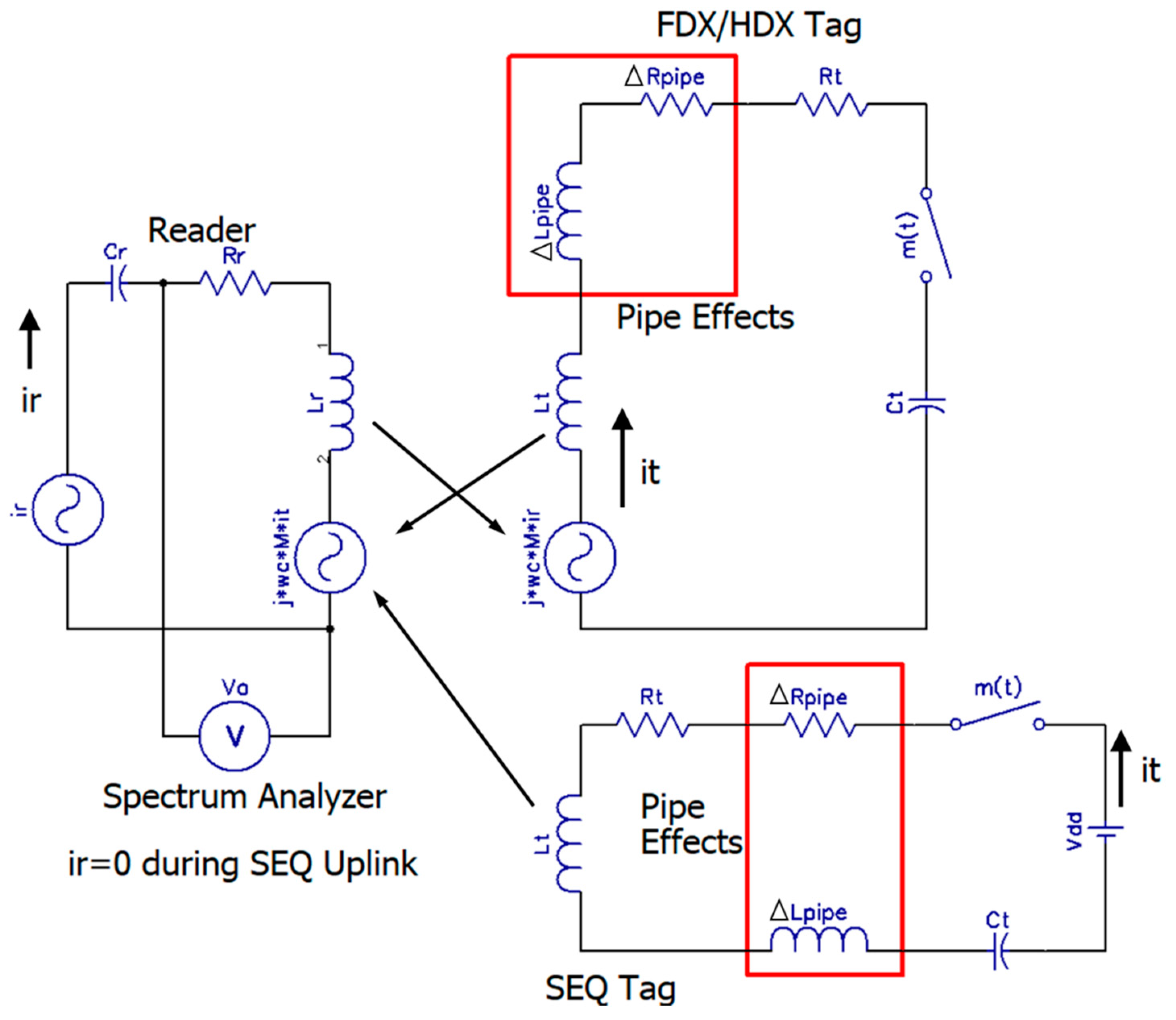
The presence of the carbon steel pipe in the vicinity of the RFID tags introduces additional parasitics ΔLpipe and ΔRpipe on the tag sides as shown in Figure 10 and verified with measurements in the following section. ΔLpipe represents the additional change in the inductance of the tag coil due to the change in the magnetic flux through it due to the presence of magnetic carbon steel pipe. ΔRpipe represents the change in the resistance of the tag coil due to magnetic proximity effects of the carbon steel pipe. The time varying flux given out by the tag coil induces eddy currents in the metallic pipe walls. The reverse flux given out by these pipe eddy currents tend to push the charges through the tag coil to one side, thereby increasing the tag coil’s total resistance.
- ir: Current supplied by current amplifier
- Lr and Rr: Inductance and resistance of reader coil
- Zr: Total impedance of reader coil
- Cr: Series resonating cap for reader coil
- Vo: Reader voltage output
- M: Mutual inductance between reader and tag coils
- it: Tag current
- Lt and Rt: Inductance and resistance of tag coil
- Ct: Series resonating cap for reader coil
- m(t): Data modulation introduced in the tag current by the PIC toggling the switch
The introduction of ΔLpipe detunes the tag coils off its resonance frequencies, which along with ΔRpipe lowers the overall current on the tag side (it). The change in the tag coil inductances by ΔLpipe also alters the mutual impedance between the tag and reader. Consequently, the data modulated voltage induced by the tag on the reader side (Vo) is also affected for both RFID systems as shown in Equations (9) and (10). α represents change in the output voltages due to changes in the gain of the current amplifier that occurs due to a shift in its output impedance that is typically set to the low coil impedance. This can be due to parallel connections such as high impedance receiver circuitry in the spectrum analyzer and voltage. The parasitic effects of the carbon steel pipe on the tag coil’s inductance and resistance along with its effect on the received uplink signal are covered in the following section.
- ir: Current supplied by current amplifier
- Lr and Rr: Inductance and resistance of reader coil
- Zr Total impedance of reader coil
- Cr: Series resonating cap for reader coil
- Vo: Reader voltage output
- M: Mutual inductance between reader and tag coils
- it: Tag current
- Lt and Rt: Inductance and resistance of tag coil
- ΔLpipe and ΔRpipe: Changes in tag coil inductance and resistance due to pipe effects
- Ct: Series resonating cap for reader coil
- m(t): Data modulation introduced in the tag current by the PIC toggling the switch
4. Measurements of RFID FDX/HDX and SEQ Communication System on Carbon Steel Pipes
4.1. Test Comparison between FDX/HDX and SEQ RFID Uplink Data Transmission
A number of measurements were taken to study the effects of the commercial ASTM A-53 carbon steel pipe (American Standard for Testing and Measurement) on the sensor tag coils in frequency bands suited for wireless uplink data communication in both FDX/HDX and SEQ RFID systems. The following measurement tools were used for measurements: A BK Precision 895 impedance analyzer for coil impedance measurements up to 1 MHz, a Tektronix TDS 2024B oscilloscope for voltage measurements, an Aaronia near-field magnetic probe set for magnetic field measurements, a Tektronix RSA306B spectrum analyzer for wireless link measurements. The pipe used was 2.14 m (7 ft) long, with an inner diameter of 21 cm (8.25 in), a wall thickness of 0.64 cm (1/4 in), and made of carbon steel.
It is well known that the presence of metal can have a significant impact on the inductance of a coil/antenna. As mentioned earlier, the presence of a magnetic material in the path of the flux generated by the tag coil can increase or decrease the total flux through the coil due to magnetic boundary conditions. The net change in flux can depend on the pipe material and frequency and can either increase or decrease the net tag coil inductance [10].
The extent of detuning in the inductance of the tag coils during uplink data transmission in both RFIDs is shown in Figure 11. The inductance variation is most significant when in very close proximity to the pipe (approximately 0–10 cm) with significantly more variation in the FDX/HDX RFIDs uplink data frequency band compared to the SEQ RFID. The tag coil inductance (Lt + ΔLpipe) drops from 1.31 to 0.91 mH for tag–pipe distance of between 10 cm or higher and 0 cm reflecting a net decrease of 0.4 mH (ΔLpipe) in the FDX/HDX uplink data communication frequency band of around 105 kHz. By comparison, the same tag coil used for SEQ RFID shows a drop from 1.19 mH to 0.96 mH over the same tag pipe separation distance with a net drop of only (ΔLpipe) 0.23 mH around the SEQ uplink data communication frequency band of 16 kHz.
At high frequencies, the AC resistance of the tag coil is also higher due to skin depth losses and magnetic proximity effects due to nearby AC current flow. Skin depth losses in the tag coil were minimized by using multi-strand Litz wire. However, magnetic proximity effects on the tag coil due to the pipe were observed as shown in the AC resistance of the tag coil for SEQ and FDX/HDX RFIDs in Figure 12. Magnetic fields produced by AC current flow in the tags induce eddy currents in the adjacent metallic pipe walls. The magnetic field produced by these eddy currents also induce magnetic fields that hinder charge flow through the tag coil, thereby increasing its AC resistance. Additionally, in the case of the FDX/HDX RFIDs, the magnetic fields produced by the simultaneously on 105 kHz downlink transmission also marginally increases AC resistance of the tag coil at close range. This AC resistance is induced in series with the tag coil’s low internal resistance and tag circuitry impedance and can significantly reduce the tag’s input voltage during downlink and also the tag current during uplink data transmission thereby limiting the downlink powering and uplink data communication range. The magnetic proximity effects of the ASTM A-53 steel pipe on the tag coil at FDX/HDX and SEQ uplink frequencies were empirically measured as shown in Figure 12. Both RFID systems experience similar magnetic proximity effects of the pipe during downlink power transmission. However, for the uplink, the FDX/HDX tag’s AC resistance (Rt + ΔRpipe) increased from 2.2 to 48 ohms an increase of 45.8 ohms (ΔRpipe). By comparison the SEQ RFID tag coil’s AC resistance increased from 0.37 to 14 ohms as shown in Figure 12.
The effect of these changes in tag coil impedance due to pipe walls can be seen in the tag coil voltage for FDX/HDX and SEQ RFID systems as shown in Figure 13a,b, respectively. For the FDX/HDX RFID system, the change in coil inductance and subsequent detuning from coil’s resonating frequency along with the increase in the coil’s AC resistance of the tag coil results in a drop of tag coil voltage by 85%. By comparison, the SEQ RFID system only registers a 10% drop in the tag coil data voltage. The SEQ system’s better performance is also helped by the presence of Riso in the uplink data signal path which results in a lower change in Rac of the tag coil. Riso is necessary in a SEQ system to prevent the rapid draining of the energy storage capacitor during uplink data transmission. Slowing the current drain from the energy capacitors allows for a longer transmission and prevents the MCU from losing power during transmit periods. This is not an option in HDX/FDX because adding current-slowing resistors in that case would also reduce incoming power during downlink power transmission, thereby significantly reducing downlink powering range. A similar study in [8] shows a metal sheet at the back of the coil reducing the field received by it by 13.26 dB in a 13.56 MHz FDX/HDX RFID. By comparison, in this study a 1/4-inch-thick pipe shows the simulated voltage through the FDX/HDX RFID tag drop by 85% peak-to-peak of its original value which translates to a 16.5 dB drop.
The effect of the industry-standard carbon steel pipe on the overall uplink wireless data communication link in FDX/HDX and SEQ RFIDs was next characterized by measuring the received data signal power level (RSSI) on the reader side with the help of a Tektronics RSA 306B spectrum analyzer. A simple on-off-keying type modulation was used for both RFIDs at a data frequency of 16 kHz to transmit consecutive 1s and 0s for the uplink communication tests. The measured spectrum plots of the received data signal for FDX/HDX and SEQ RFIDs are shown in Figure 14a,b, respectively, for a tag/pipe and reader separation distance of 80 cm. The spectral measurements shown are with the maximum-hold feature to show the captured RSSI signal level better. Subsequent measurements including in Figure 15 were carried out with the spectrum analyzer’s averaging feature to filter out any noise introduced along the uplink data channel path. Additional measurements of the received data signal level for different separation distances between the reader and tag were carried out with and without pipe for both RFIDs and are shown as a function of this distance in Figure 15.
Over an increasing separation distance of between 80 and 125 cm, both RFIDs experience attenuation due to propagation loss. Over the same increasing range, the uplink data signal power measured on the reader side decreases from −69 to −93 dBm for the FDX/HDX RFID system without the pipe. By comparison, the received uplink data signal measured between −65.8 and −78.4 dBm over the same range for the SEQ system without the pipe as shown in Figure 15. However, with the presence of the pipe (tag–pipe separation distance = 0 cm), the uplink data signal was measured to be between −80.2 and −140.1 dBm over the same range registering approximately a 11.54 dBm drop for the FDX/HDX RFID system. By comparison, the uplink data signal dropped to between −70 and −83.1 dBm under the same conditions for the SEQ RFID registering approximately a 3.28 dBm drop over the full range due to pipe effects.
4.2. Wireless Test Characterization of SEQ RFID System with Carbon Steel Pipe
Further tests to characterize the proposed SEQ tag’s communication was carried out with and without the pipe to study pip effects on the SEQ RFID’s received packet rate and signal-to-noise ratio.
For these uplink data communication tests, a 32 bit long data packet with on-off-keying (OOK) modulation and a simple 1/0 bit encoding was used. Figure 16 shows a specimen of this data packet measured on the reader side with very little reader–tag separation. Subsequent tests were done with reader–tag separation of 80 cm or more. The use of the charge pump, energy storage capacitor, and PMU ensures a consistent uplink transmission characteristic from the tag over the tag–reader range due to which the Bit error rate never increases to above 0%. It does, however, affect the packet data rate and tag charge-up times, which is further slowed down due to pipe effects as shown in Figure 17 and also Figure 6. For a 1 mF energy storage capacitor and the PMU input set to trigger the uplink transmission at 4.04 V (Vstore), the packet rate varies between 8.4 and 4 packets per second (pps) between a tag–reader range of 80 and 125 cm to transmit a packet consisting of 34 data bits including a start bit and parity bit without the pipe. With the pipe, the added coil impedances (ΔLpipe and ΔRpipe) slows down the downlink charging due to which the packet rate drops by less than 2 packets till about 105 cm beyond which the packet rate drops sharply as seen in Figure 17. This is the point where Vstore starts to drop below 4.04 V.
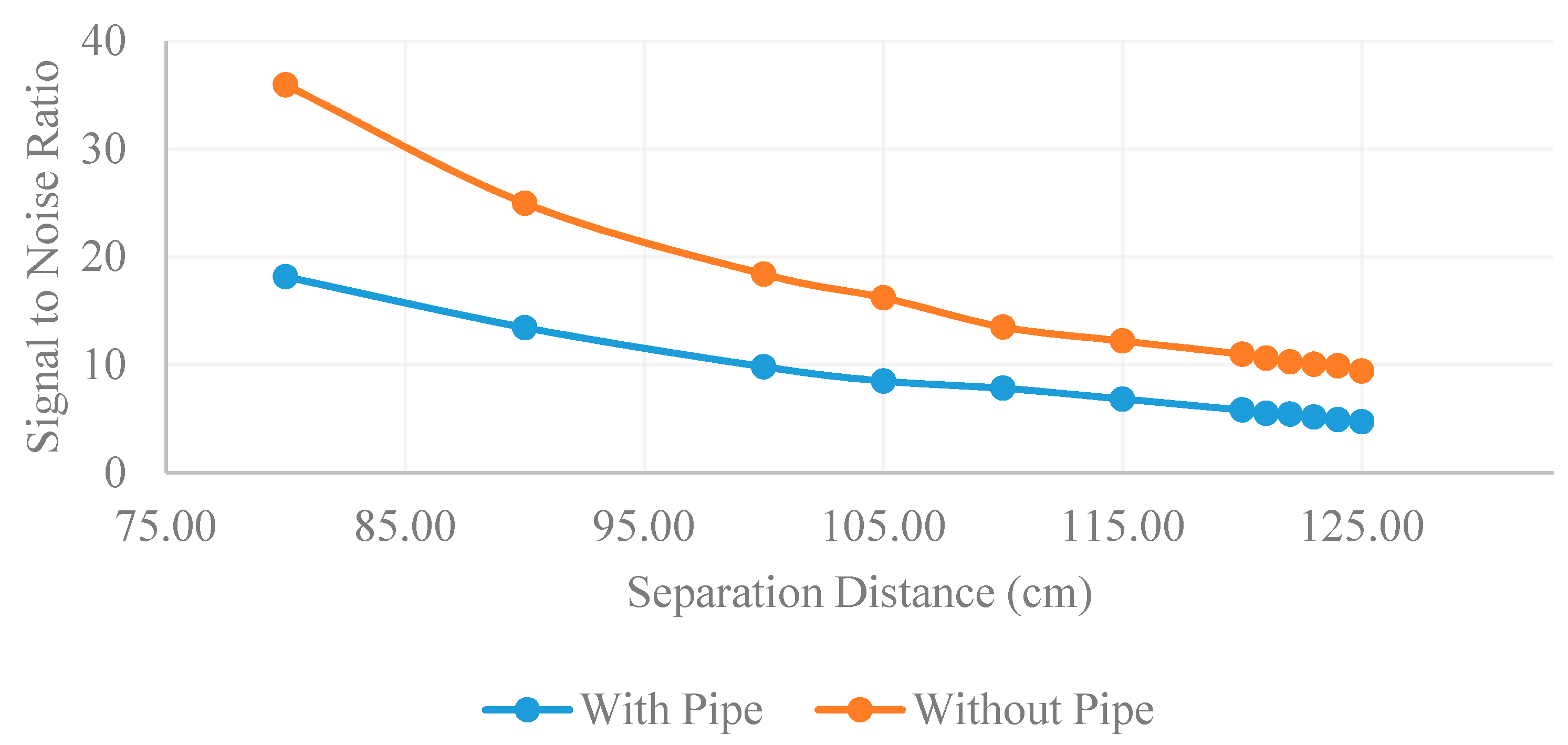
The signal-to-noise ratio of the data signal was measured on the reader side with the Arduino Due after amplification using the variance of the on and off signals. The on signal is measured by measuring the variance of a binary ’1’, and the off is measured by the variance of a binary ’0’ as this is essential noise as shown in Equation (11). The SNR of the SEQ system over a range of 80 to125 cm between reader and tag with and without pipe are shown in Figure 18. Essentially, the pipe halves the SNR of the system (−3 dB) which is comparable to the 3.28 dB drop presented in the communication tests in Figure 15.
- σ2signal: Signal variance σ2noise: Noise variance
- σ21: Binary ‘1’ variance σ20: Binary ‘0’ variance
5. Conclusions
In conclusion, a sequential RFID communication platform has been designed, tested, and compared to conventional RFID communication methods. This platform shows several advantages and few disadvantages over conventional duplex RFID platforms. The design has very good communication range, and with adjustments to the power circuitry on the tag could achieve a range well beyond the 125 cm presented here. It has been shown that the performance of the designed SEQ RFID system in the presence of the carbon steel pipe is more effective and immune when compared to conventional FDX/HDX RFID. The pipe caused a constant 3.28 dB drop in received signal for sequential communication, while a constant 11.54 dB drop for FDX/HDX over a range of 80–125 cm. These results are due to several factors. First, the detuning effect of the industry standard ASTM A-53 carbon steel pipe on the tag coil’s inductance is less drastic at the SEQ RFID’s uplink data frequency of 16 kHz compared to the FDX/HDX’s 105 ± 16 kHz. Second, the AC resistance due to the magnetic proximity effects of the pipe wall is lower at the SEQ RFID’s uplink data frequency of 16 kHz compared to the FDX/HDX’s 105 ± 16 kHz. As a result, the tag current in the SEQ RFID tag is less attenuated than the FDX/HDX tag, thereby resulting in a higher received signal level on the reader side. Thirdly, the magnetic backscattering nature of uplink data communication in the FDX/HDX system also results in a lower overall mutual induction between the reader and tag for the FDX/HDX RFID compared to the one sided uplink data transmission in the SEQ RFID. This is mainly due to the drop in the tag’s coil inductance in the presence of the pipe. While further tests of both RFID systems could not be performed in soil and water conditions due to lab/building restrictions, the proposed SEQ system uses lower frequency magnetic fields at 16 kHz for the uplink data communication. At these bands, soil and moisture are expected to offer the same propagation characteristics as air as reported in [6]. These factors led to a more immune SEQ system than the conventional FDX/HDX system. The range of the designed sequential system was also tested in air with an industry standard ASTM A-53 carbon steel pipe, and the results show a maximum depth of 125 cm. This range and study could be further improved by optimizing the power circuitry and coils to account for the pipe effects and by conducting tests in presence of soil/water to verify the proposed design’s immunity against them.
6. Patents
Patents pending.
Author Contributions
Conceptualization, R.V.; methodology, R.V., B.T.; software, R.V., B.T.; validation, R.V., B.T.; formal analysis, R.V., B.T.; investigation, R.V., B.T.; resources, R.V.; data curation, R.V., B.T.; writing—original draft preparation, R.V., B.T.; writing—review and editing, R.V., B.T.; supervision, R.V.; project administration, R.V.; funding acquisition, R.V. Authorship has been limited to those who have contributed substantially to the work reported.
Funding
NSERC (Canada), University of Calgary Pipeline Engineering Center, Enbridge Inc. Bluesky grant, CMC Microsystems (Canada).
Conflicts of Interest
The authors declare no conflict of interest. The funders had no role in the design of the study; in the collection, analyses, or interpretation of data; in the writing of the manuscript, or in the decision to publish the results.
References
- Ryan, J.R.A. Pipelines in Canada—The Canadian Encyclopedia. 2019. Available online: https://www.thecanadianencyclopedia.ca/en/article/pipeline (accessed on 22 July 2019).
- NRCAN, Crude Oil Facts—Natural Resources Canada. Available online: https://www.nrcan.gc.ca/crude-oil-facts/20064 (accessed on 22 July 2019).
- Li, L.; Vuran, M.C.; Akyildiz, I.F. Characteristics of Underground Channel for Wireless Underground Sensor Networks. In Proceedings of the 6th Annual Mediterranean Ad Hoc Networking WorkShop, Corfu, Greece, 12–15 June 2007; pp. 92–99. [Google Scholar]
- Sun, Z.; Akyildiz, I.F. Magnetic Induction Communication for Wireless Underground Sensor Networks. IEEE Trans. Antennas Propag. 2014, 58, 2426–2435. [Google Scholar] [CrossRef]
- Curtis, J. Electromagnetic Power Attenuation in Soils Electromagnetic Power Attenuation in Soils. 2005. Available online: https://apps.dtic.mil/dtic/tr/fulltext/u2/a437109.pdf (accessed on 22 July 2019).
- Sandia National Laboratories. Measurement of Dielectric and Magnetic Properties of Soil. 1995. Available online: https://inis.iaea.org/collection/NCLCollectionStore/_Public/27/040/27040410.pdf (accessed on 22 July 2019).
- Magnetic Properties of Solids. Available online: http://hyperphysics.phy-astr.gsu.edu/hbase/Tables/magprop.html (accessed on 22 July 2019).
- Qing, X.; Chen, Z.N. Proximity Effects of Metallic Environments on High Frequency RFID Reader Antenna: Study and Applications. IEEE Trans. Antennas Propag. 2007, 55, 2882–2888. [Google Scholar] [CrossRef]
- Emmons, T.F. Radio Engineer’s Handbook, 1st ed.; McGraw Hill: New York, NY, USA, 1943. [Google Scholar]
- Sadiku, M.N. Elements of Electromagnetics, 6th ed.; Oxford University Press: New York, NY, USA, 2015. [Google Scholar]
- Sun, Z.; Wang, P.; Vuran, M.C.; Al-rodhaan, M.A.; Al-dhelaan, A.M.; Akyildiz, I.F. Ad Hoc Networks MISE-PIPE: Magnetic induction-based wireless sensor networks for underground pipeline monitoring. Ad Hoc Netw. 2011, 9, 218–227. [Google Scholar] [CrossRef]
- Sun, Z.; Akyildiz, I.F.; Kissele, S.; Member, S.; Gerstacker, W.; Member, S. Increasing the Capacity of Magnetic Induction Communications in RF-Challenged Environments. IEEE Trans. Commun. 2013, 61, 3943–3952. [Google Scholar] [CrossRef]
- Tan, X.; Sun, Z. An Optimal Leakage Detection Strategy for Underground Pipelines Using Magnetic Induction-Based Sensor Networks; Springer: Berlin-Heidelberg, Germany, 2013; Volume 7992, pp. 414–425. [Google Scholar]
- Lin, S.; Member, S.; Akyildiz, I.F.; Wang, P.; Sun, Z. Distributed Cross-Layer Protocol Design for Magnetic Induction Communication in Wireless Underground Sensor Networks. IEEE Trans. Wirel. Commun. 2015, 14, 4006–4019. [Google Scholar] [CrossRef]
- Sadeghioon, A.M.; Metje, N.; Chapman, D.N.; Anthony, C.J. SmartPipes: Smart Wireless Sensor Networks for Leak Detection in Water Pipelines. J. Sens. Actuator Netw. 2014, 3, 64–78. [Google Scholar] [CrossRef]
- Caffrey, C.M.; Häkli, J.; Hirvonen, M.; Huhtinen, I.; Nummila, K.; Lehikoinen, T. Magnetically Coupled Wireless Communication for Buried Environmental Sensor. In Proceedings of the IEEE 12th International Conference on Environment and Electrical Engineering, Wroclaw, Poland, 5–8 May 2013; pp. 1–6. [Google Scholar]
- Zarifi, M.H.; Deif, S.; Daneshmand, M. Wireless passive RFID sensor for pipeline integrity monitoring. Sens. Actuators A 2017, 261, 24–29. [Google Scholar] [CrossRef]
- 3M Locating and Marking System. Available online: https://multimedia.3m.com/mws/media/683617O/3m-locating-and-marking-system-product-bulletin-lr-pdf.pdf (accessed on 22 July 2019).
- Elydan. RFID Identification for Underground Utilities—Eliot Rfid Marker. Available online: https://www.rybbtp.fr/portfolio-item/eliot-rfid-markers/?lang=en (accessed on 22 July 2019).
- Finkenzeller, K.; Waddington, R. RFID Handbook; John Wiley and Sons: Chichester, UK, 2003. [Google Scholar]
- Lee, Y. Antenna Circuit Design for RFID Applications. 2003. Available online: http://ww1.microchip.com/downloads/en/appnotes/00710c.pdf (accessed on 22 July 2019).
- Microchip. dsPIC33/PIC24 Family Reference Manual. Available online: https://www.microchip.com/wwwproducts/en/PIC24F16KA101 (accessed on 22 July 2019).
Figure 1.
Proposed radio-frequency-identification tags (RFID) system sensor platform for communicating with buried pipelines. Typical sensors include temperature, moisture, and strain-gauge sensors that run from a 3 V supply.
Figure 1.
Proposed radio-frequency-identification tags (RFID) system sensor platform for communicating with buried pipelines. Typical sensors include temperature, moisture, and strain-gauge sensors that run from a 3 V supply.

Figure 2.
Diagram of full/half duplex and sequential RFID systems. Black bars indicate wireless transmission. Reproduced from [20].
Figure 2.
Diagram of full/half duplex and sequential RFID systems. Black bars indicate wireless transmission. Reproduced from [20].

Figure 3.
Diagram of full/half duplex and sequential RFID systems.

Figure 4.
Power spectrum diagram for full/half duplex and sequential RFID systems. Downlink power transmission frequency is fc for full/half duplex (FDX/HDX) and sequential (SEQ) RFID systems. Uplink data frequency is fc ± fm for FDX/HDX and fd for SEQ RFID systems.
Figure 4.
Power spectrum diagram for full/half duplex and sequential RFID systems. Downlink power transmission frequency is fc for full/half duplex (FDX/HDX) and sequential (SEQ) RFID systems. Uplink data frequency is fc ± fm for FDX/HDX and fd for SEQ RFID systems.

Figure 5.
Preliminary measurement of tag coil’s AC resistance vs frequency when mounted on pipe. Measurements show an approximate linear rise in the AC resistance of the tag coil due to magnetic proximity effects of the carbon steel pipe by about 0.5 ohms per kHz, which reduces the tag input voltage Vin–pk with increasing frequency.
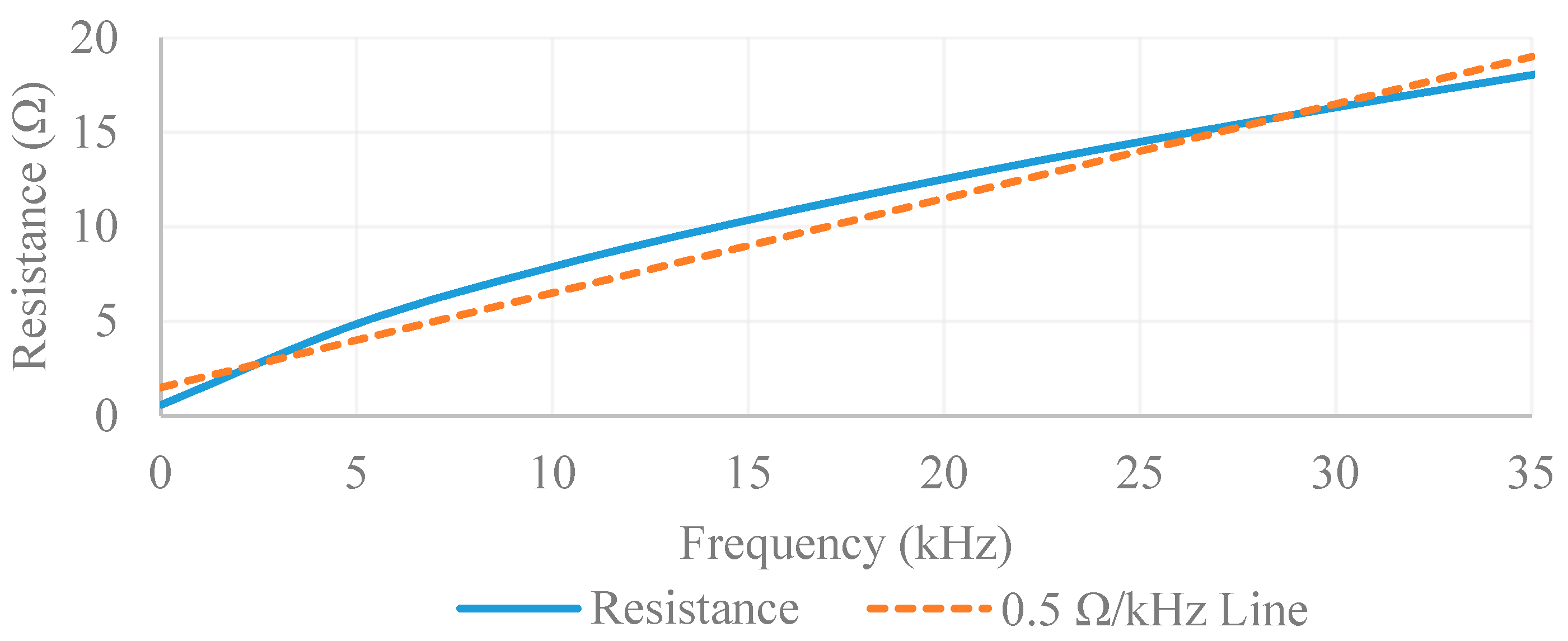
Figure 6.
Architecture of SEQ tag and measured oscilloscope readings of important signals (top—signals show cold starting of tag during downlink power transmission; bottom—signals show uplink transmission).
Figure 6.
Architecture of SEQ tag and measured oscilloscope readings of important signals (top—signals show cold starting of tag during downlink power transmission; bottom—signals show uplink transmission).

Figure 7.
Reader system implemented to study FDX/HDX and SEQ RFID system behavior on carbon steel pipes. Signal generator: Agilent 33120; Current Amplifier: Accel TS 250; Amplifier: Linear Technology LT1226; Spectrum Analyzer: Tektronics RSA 306B; Processor for Rx processing: Arduino Due with Atmel AT91SAM3X8E.

Figure 8.
Test setup used to test out FDX/HDX and SEQ RFID systems with an industry standard ASTM A-53 carbon steel pipe. Non-magnetic materials such as foam were used in the mounts on the reader and tag side so as not to affect the downlink and uplink magnetic fields. Other magnetic objects were placed at least 1 m away and outside the transmission axis of the coils. Measurements with and without the pipe were carried out by keeping the setup of the tag and reader constant for relative measurements. Distance for wireless link measurements was measured using a Bosch laser meter. Tests were done without sand/soil/moisture since at 16 and 105 kHz soil/moisture magnetic permeabilities are same as air [6].

Figure 9.
SEQ and FDX/HDX RFID equivalent circuits without pipe.

Figure 10.
SEQ and FDX/HDX RFID equivalent circuits with pipe.

Figure 11.
Pipe effect on inductance of the tag coil vs tag–pipe separation distance.

Figure 12.
Pipe effect on resistance of the tag coil as distance from pipe increases. Values at 25 cm are 0.37 ohms (SEQ 16) and 2.2 (FDX/HDX).
Figure 12.
Pipe effect on resistance of the tag coil as distance from pipe increases. Values at 25 cm are 0.37 ohms (SEQ 16) and 2.2 (FDX/HDX).
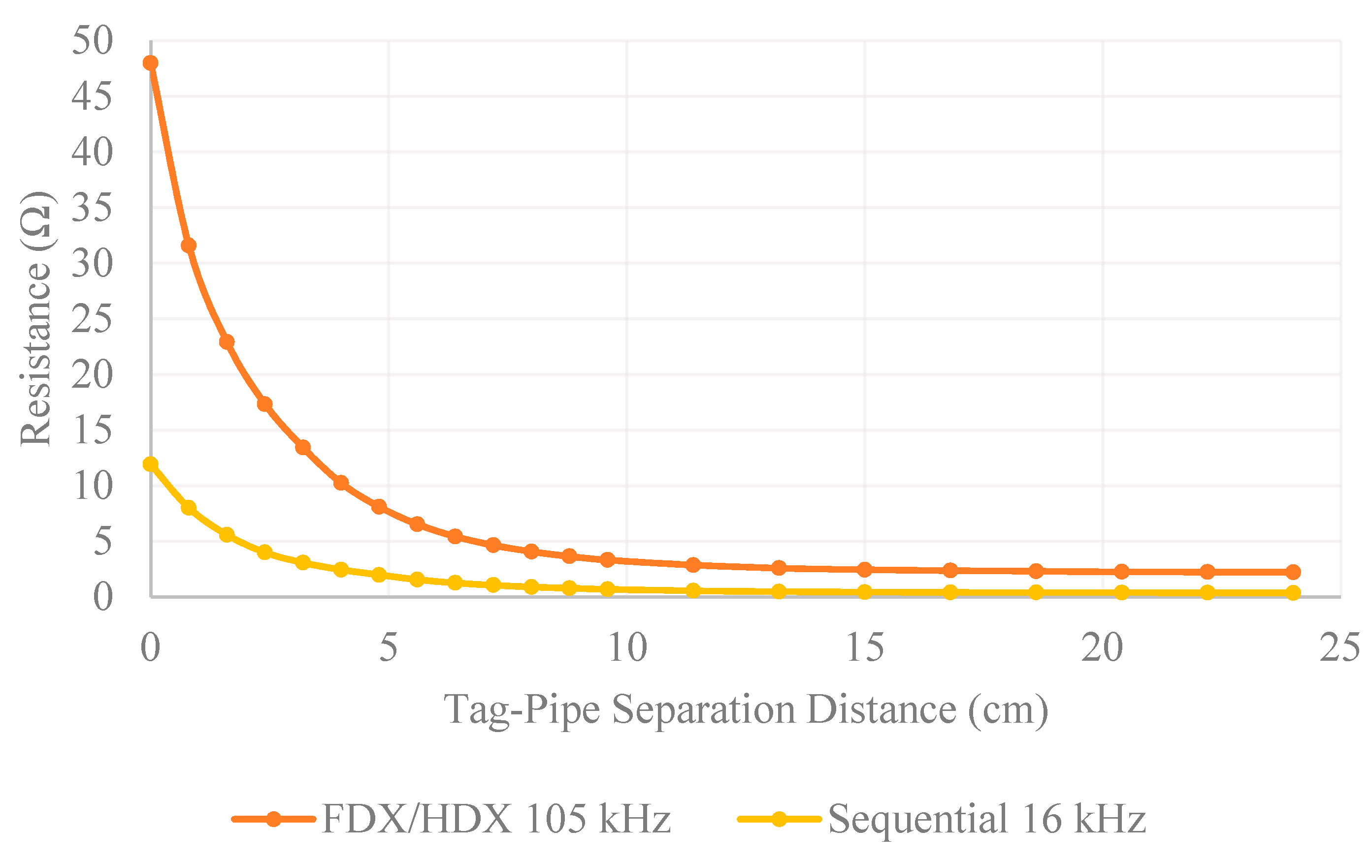
Figure 13.
Simulated effects of the pipe on tag coil voltages at 80 cm separation distance between reader and tag. Downlink power increased for FDX/HDX to ensure similar power level is received on reader side as SEQ. (a) FDX/HDX tag coil voltage; (b) SEQ tag coil voltage.
Figure 13.
Simulated effects of the pipe on tag coil voltages at 80 cm separation distance between reader and tag. Downlink power increased for FDX/HDX to ensure similar power level is received on reader side as SEQ. (a) FDX/HDX tag coil voltage; (b) SEQ tag coil voltage.
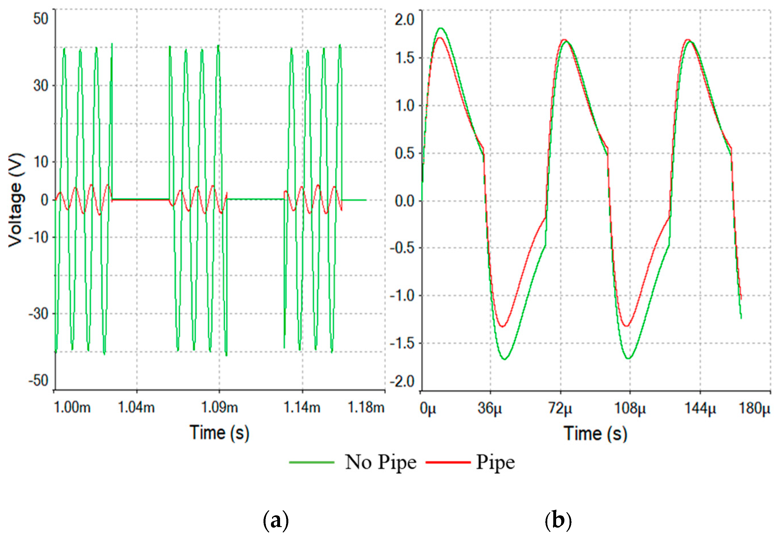
Figure 14.
Measured spectrum plots of the uplink data communication signal at a reader–tag distance of 80 cm with and without pipe for: (a) FDX/HDX RFID communication system; (b) SEQ RFID communication system.
Figure 14.
Measured spectrum plots of the uplink data communication signal at a reader–tag distance of 80 cm with and without pipe for: (a) FDX/HDX RFID communication system; (b) SEQ RFID communication system.

Figure 15.
Measured reader received signal power level vs tag–reader separation distance for FDX/HDX and SEQ RFIDs with and without pipe effects.
Figure 15.
Measured reader received signal power level vs tag–reader separation distance for FDX/HDX and SEQ RFIDs with and without pipe effects.
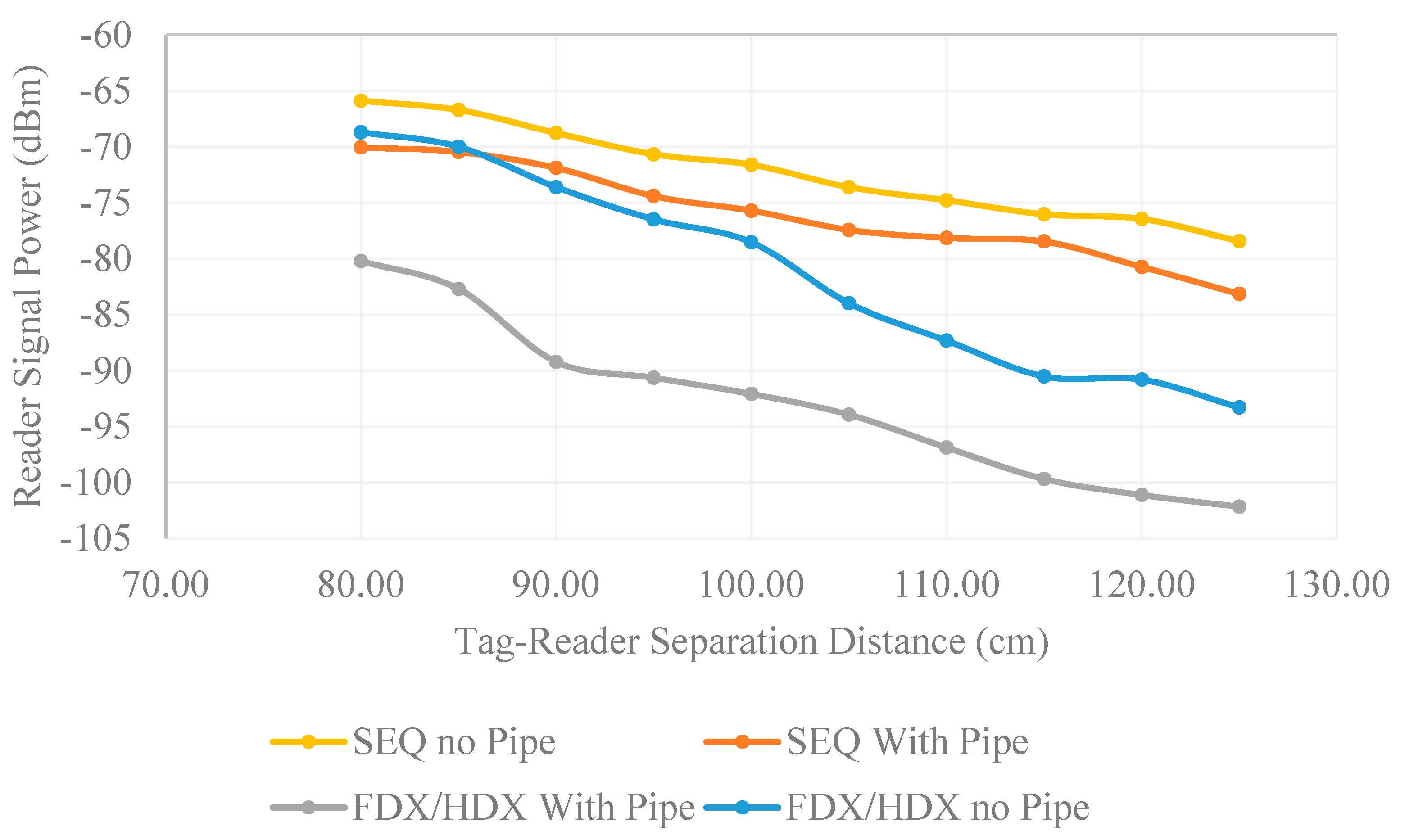
Figure 16.
Waveform of an entire packet measured on the reader side. Data shown is 0x6F70 656E.

Figure 17.
Transmission packet rate of designed sequential system vs tag–reader distance.

Figure 18.
Signal-to-noise ratio of received sequential signal vs tag–reader distance.

Table 1.
Comparison of RFID Systems. (NM means ‘Not mentioned’).
| Ref. | Freq. | Prototype | Communication | Battery | Function (Output Voltage) | Range | Works on Metal |
|---|---|---|---|---|---|---|---|
| [11] | 10 MHz | yes | Custom MI | no | Sensing | 10 m (theory) | yes |
| [15] | 433 MHz | no | HDX | yes | Sensing (2.5 V) | NM | no |
| [17] | 100 MHz | yes | FDX | no | Sensing (NA) | 1 cm | yes |
| [16] | 125 kHz | no | LF MI | yes | Sensing temp | 12 m | no |
| [18] | 0.6–200 kHz | no | Custom RFID | no | Marking (1 V) | 1.8 m | no |
| [19] | 13.5 MHz | yes | FDX | no | Marking (1 V) | 1.5 m | yes |
| This work | 105/16 kHz | yes | SEQ | no | Sensing (2.5 V) | 1.25 m | yes |
© 2019 by the authors. Licensee MDPI, Basel, Switzerland. This article is an open access article distributed under the terms and conditions of the Creative Commons Attribution (CC BY) license (http://creativecommons.org/licenses/by/4.0/).
Share and Cite
MDPI and ACS Style
Vyas, R.; Tye, B. A Sequential RFID System for Robust Communication with Underground Carbon Steel Pipes in Oil and Gas Applications. Electronics 2019, 8, 1374. https://doi.org/10.3390/electronics8121374
AMA Style
Vyas R, Tye B. A Sequential RFID System for Robust Communication with Underground Carbon Steel Pipes in Oil and Gas Applications. Electronics. 2019; 8(12):1374. https://doi.org/10.3390/electronics8121374
Chicago/Turabian StyleVyas, Rushi, and Bailey Tye. 2019. "A Sequential RFID System for Robust Communication with Underground Carbon Steel Pipes in Oil and Gas Applications" Electronics 8, no. 12: 1374. https://doi.org/10.3390/electronics8121374
Note that from the first issue of 2016, this journal uses article numbers instead of page numbers. See further details here.